1
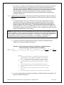
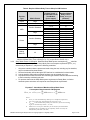
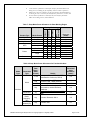
ENERGY STAR® Product Specification for Imaging Equipment Eligibility Criteria Version 2.0 Following is the Version 2.0 ENERGY STAR Product Specification for Imaging Equipment. A product shall meet all of the identified criteria if it is to earn the ENERGY STAR. 1 DEFINITIONS A) Product Types: 1) Printer: A product whose primary function is to generate paper output from electronic input. A printer is capable of receiving information from single-user or networked computers, or other input devices (e.g., digital cameras). This definition is intended to cover products that are marketed as printers, and printers that can be field-upgraded to meet the definition of an MFD. 2) Scanner: A product whose primary function is to convert paper originals into electronic images that can be stored, edited, converted, or transmitted, primarily in a personal computing environment. This definition is intended to cover products that are marketed as scanners. 3) Copier: A product whose sole function is to produce paper duplicates from paper originals. This definition is intended to cover products that are marketed as copiers, and upgradeable digital copiers (UDCs). 4) Facsimile (Fax) Machine: A product whose primary functions are (1) to scan paper originals for electronic transmission to remote units, and (2) to receive electronic transmissions for conversion to paper output. A fax machine may also be capable of producing paper duplicates. Electronic transmission is primarily over a public telephone system, but may also be via a computer network or the Internet. This definition is intended to cover products that are marketed as fax machines. 5) Multifunction Device (MFD): A product that performs two or more of the core functions of a Printer, Scanner, Copier, or Fax Machine. An MFD may have a physically integrated form factor, or it may consist of a combination of functionally integrated components. MFD copy functionality is considered to be distinct from single-sheet convenience copying functionality sometimes offered by fax machines. This definition includes products marketed as MFDs, and “multi-function products” (MFPs). 6) Digital Duplicator: A product sold as a fully-automated duplicator system through the method of stencil duplicating with digital reproduction functionality. This definition is intended to cover products that are marketed as digital duplicators. 7) Mailing Machine: A product whose primary function is to print postage onto mail pieces. This definition is intended to cover products that are marketed as mailing machines. B) Marking Technologies: 1) Direct Thermal (DT): A marking technology characterized by the burning of dots onto coated print media that is passed over a heated print head. DT products do not use ribbons. 2) Dye Sublimation (DS): A marking technology characterized by the deposition (sublimation) of dye onto print media as energy is supplied to heating elements. ENERGY STAR Program Requirements for Imaging Equipment – Eligibility Criteria Page 1 of 18 3) Electro-photographic (EP): A marking technology characterized by the illumination of a photoconductor in a pattern representing the desired output image via a light source, development of the image with particles of toner using the latent image on the photoconductor to define the presence or absence of toner at a given location, transfer of the toner to the final print media, and fusing to cause the output to become durable. For purposes of this specification, Color EP products simultaneously offer three or more unique toner colors, while Monochrome EP products simultaneously offer one or two unique toner colors. This definition includes Laser, Light Emitting Diode (LED), and Liquid Crystal Display (LCD) illumination technologies. 4) Impact: A marking technology characterized by the formation of the desired output image by transferring colorant from a “ribbon” to the print media via an impact process. This definition includes Dot Formed Impact and Fully Formed Impact. 5) Ink Jet (IJ): A marking technology characterized by the deposition of colorant in small drops directly to the print media in a matrix manner. For purposes of this specification, Color IJ products offer two or more unique colorants at one time, while Monochrome IJ products offer one colorant at a time. This definition includes Piezo-electric (PE) IJ, IJ Sublimation, and Thermal IJ. This definition does not include High Performance IJ. 6) High Performance IJ: An IJ marking technology that includes nozzle arrays that span the width of a page and/or the ability to dry ink on the print media via supplemental media heating mechanisms. High-performance IJ products are used in business applications usually served by electro-photographic marking products. 7) Solid Ink (SI): A marking technology characterized by ink that is solid at room temperature and liquid when heated to the jetting temperature. This definition includes both direct transfer and offset transfer via an intermediate drum or belt. 8) Stencil: A marking technology characterized by the transfer of images onto print media from a stencil that is fitted around an inked drum. 9) Thermal Transfer (TT): A marking technology characterized by the deposition of small drops of solid colorant (usually colored waxes) in a melted/fluid state directly to print media in a matrix manner. TT is distinguished from IJ in that the ink is solid at room temperature and is made fluid by heat. C) Operational Modes: 1) On Mode: a) Active State: The power state in which a product is connected to a power source and is actively producing output, as well as performing any of its other primary functions. b) Ready State: The power state in which a product is not producing output, has reached operating conditions, has not yet entered into any lower-power modes, and can enter Active State with minimal delay. All product features can be enabled in this state, and the product is able to return to Active State by responding to any potential inputs, including external electrical stimulus (e.g., network stimulus, fax call, or remote control) and direct physical intervention (e.g., activating a physical switch or button). ENERGY STAR Program Requirements for Imaging Equipment – Eligibility Criteria Page 2 of 18 2) Off Mode: The power state that the product enters when it has been manually or automatically switched off but is still plugged in and connected to the mains. This mode is exited when stimulated by an input, such as a manual power switch or clock timer to bring the unit into Ready State. When this state is resultant from a manual intervention by a user, it is often referred to as Manual Off, and when it is resultant from an automatic or predetermined stimuli (e.g., a delay time or clock), it is often referred to as Auto-off.1 3) Sleep Mode: A reduced power state that a product enters either automatically after a period of inactivity (i.e., Default Delay Time), in response to user manual action (e.g., at a user-set time of day, in response to a user activation of a physical switch or button), or in response to external electrical stimulus (e.g., network stimulus, fax call, remote control). For products evaluated under the TEC test method, Sleep Mode permits operation of all product features (including maintenance of network connectivity), albeit with a possible delay to transition into Active State. For products evaluated under the OM test method, Sleep Mode permits operation of a single active network interface, as well as a fax connection if applicable, albeit with a possible delay to transition into Active State. 4) Standby: The lowest power consumption state which cannot be switched off (influenced) by the user and that may persist for an indefinite time when the product is connected to the main electricity supply and used in accordance with the manufacturer’s instructions.1,2 Standby is the product’s minimum power state. For Imaging Equipment products addressed by this specification, the “Standby” Mode usually corresponds to Off Mode, but may correspond to Ready State or Sleep Mode. A product cannot exit Standby and reach a lower power state unless it is physically disconnected from the main electricity supply as a result of manual manipulation. D) Media Format: 1) Large Format: Products designed for A2 media and larger, including those designed to accommodate continuous-form media greater than or equal to 406 mm wide. Large-format products may also be capable of printing on standard-size or small-format media. 2) Standard Format: Products designed for standard-sized media (e.g., Letter, Legal, Ledger, A3, A4, B4), including those designed to accommodate continuous-form media between 210 mm and 406 mm wide. Standard-size products may also be capable of printing on small-format media. a) A3-capable: Standard Format products with a paper path width equal to or greater than 275 mm. 3) Small Format: Products designed for media sizes smaller than those defined as Standard (e.g., A6, 4”x6”, microfilm), including those designed to accommodate continuous-form media less than 210 mm wide. 4) Continuous Form: Products that do not use a cut-sheet media format and that are designed for applications such as printing of bar codes, labels, receipts, banners, and engineering drawings. Continuous Form products can be Small, Standard, or Large Format. E) Additional Terms: 1) Automatic Duplexing: The capability of a copier, fax machine, MFD, or printer to produce images on both sides of an output sheet, without manual manipulation of output as an intermediate step. A product is considered to have automatic duplexing capability only if all accessories needed to produce duplex output are included with the product upon shipment. 1 For the purposes of this specification “mains” or the “main electricity supply” refers to the input power source, including a dc power supply for products that operate solely off dc power. 2 IEC 62301 Ed. 1.0 – Household electrical appliances – Measurement of standby power. ENERGY STAR Program Requirements for Imaging Equipment – Eligibility Criteria Page 3 of 18 2) Data Connection: A connection that permits the exchange of information between the Imaging Equipment and one external powered device or storage medium. 3) Default Delay Time: The time set by the manufacturer prior to shipping that determines when the product will enter a lower-power mode (e.g., Sleep, Auto-off) following completion of its primary function. 4) Digital Front-end (DFE): A functionally-integrated server that hosts other computers and applications and acts as an interface to Imaging Equipment. A DFE provides greater functionality to the Imaging Equipment. a) A DFE offers three or more of the following advanced features: i. ii. iii. iv. v. vi. vii. Network connectivity in various environments; Mailbox functionality; Job queue management; Machine management (e.g., waking the Imaging Equipment from a reduced power state); Advanced graphic user-interface (UI); Ability to initiate communication with other host servers and client computers (e.g., scanning to email, polling remote mailboxes for jobs); or Ability to post-process pages (e.g., reformatting pages prior to printing). b) Type 1 DFE: A DFE that draws its dc power from its own ac power supply (internal or external), which is separate from the power supply that powers the Imaging Equipment. This DFE may draw its ac power directly from a wall outlet, or it may draw it from the ac power associated with the Imaging Equipment’s internal power supply. A Type 1 DFE may be sold standard with the Imaging Equipment product or as an accessory. c) Type 2 DFE: A DFE that draws its dc power from the same power supply as the Imaging Equipment with which it operates. Type 2 DFEs must have a board or assembly with a separate processing unit that is capable of initiating activity over the network and can be physically removed, isolated, or disabled using common engineering practices to allow power measurements to be made. d) Auxiliary Processing Accelerator (APA): A computing expansion add-in card installed in a general-purpose add-in expansion slot of the DFE (e.g., GPGPU installed in a PCI slot). 5) Network Connection: A connection that permits the exchange of information between the Imaging Equipment and one or more external powered devices. 6) Functional Adder: A data or network interface or other component that adds functionality to the marking engine of an Imaging Equipment product and provides a power allowance when qualifying products according to the OM method. 7) Operational Mode (OM): For the purposes of this specification, a method of comparing product energy performance via an evaluation of power (measured in watts) in various operating states, as specified in Section 9 of the ENERGY STAR Imaging Equipment Test Method. 8) Typical Electricity Consumption (TEC): For the purposes of this specification, a method of comparing product energy performance via an evaluation of typical electricity consumption (measured in kilowatt-hours) during normal operation over a specified period of time, as specified in Section 8 of the ENERGY STAR Imaging Equipment Test Method. 9) Marking Engine: The fundamental engine of an Imaging Equipment product that drives image production. A marking engine relies upon functional adders for communication ability and image processing. Without functional adders and other components, a marking engine cannot acquire image data for processing and is non-functional. ENERGY STAR Program Requirements for Imaging Equipment – Eligibility Criteria Page 4 of 18 10) Base Product: The most fundamental configuration of a particular Product Model, which possesses the minimum number of functional adders available. Optional components and accessories are not considered part of a base product. 11) Accessory: A piece of peripheral equipment that is not necessary for the operation of the Base Product, but that may be added before or after shipment in order to add functionality. An accessory may be sold separately under its own model number, or sold with a base product as part of a package or configuration. 12) Product Model: An Imaging Equipment product that is sold or marketed under a unique model number or marketing name. A product model may be comprised of a base product or a base product plus accessories. 13) Product Family: A group of product models that are (1) made by the same manufacturer, (2) subject to the same ENERGY STAR qualification criteria, and (3) of a common basic design. Product models within a family differ from each other according to one or more characteristics or features that either (1) have no impact on product performance with regard to ENERGY STAR qualification criteria, or (2) are specified herein as acceptable variations within a product family. For Imaging Equipment, acceptable variations within a product family include: a) Color, b) Housing, c) Input or output paper-handling accessories, d) Electronic components not associated with the marking engine of the Imaging Equipment product, including Type 1 and Type 2 DFEs. 2 SCOPE 2.1 Included Products 2.1.1 Commercially-available products that meet one of the Imaging Equipment definitions in Section 1.A) and are capable of being powered from (1) a wall outlet, (2) a data or network connection, or (3) both a wall outlet and a data or network connection, are eligible for ENERGY STAR qualification, with the exception of products listed in Section 2.2. 2.1.2 An Imaging Equipment product must further be classified as either “TEC” or “OM” in Table 1, below, depending on the method of ENERGY STAR evaluation. Table 1: Evaluation Methods for Imaging Equipment Equipment Type Media Format Marking Technology Digital Duplicator Standard Large Standard Fax Machine Standard Mailing Machine Multifunction Device (MFD) All DT, DS, EP, SI, TT DT, DS, EP, SI, TT Stencil DT, DS, EP, SI, TT IJ DT, EP, IJ, TT Copier Standard High Performance IJ, DT, DS, EP, SI, TT ENERGY STAR Program Requirements for Imaging Equipment – Eligibility Criteria ENERGY STAR Evaluation Method TEC OM TEC TEC OM OM TEC Page 5 of 18 Equipment Type Media Format Marking Technology IJ, Impact Large Standard Printer Large or Small Scanner ENERGY STAR Evaluation Method OM DT, DS, EP, IJ, SI, TT High Performance IJ, DT, DS, EP, SI, TT IJ, Impact DT, DS, EP, Impact, IJ, SI, TT OM TEC OM OM Small High Performance IJ TEC All N/A OM 2.2 Excluded Products 2.2.1 Products that are covered under other ENERGY STAR product specifications are not eligible for qualification under this specification. The list of specifications currently in effect can be found at www.energystar.gov/products. 2.2.2 Products that satisfy one or more of the following conditions are not eligible for ENERGY STAR qualification under this specification: i. Products that are designed to operate directly on three-phase power. 3 QUALIFICATION CRITERIA 3.1 Significant Digits and Rounding 3.1.1 All calculations shall be carried out with directly measured (unrounded) values. 3.1.2 Unless otherwise specified, compliance with specification limits shall be evaluated using directly measured or calculated values without any benefit from rounding. 3.1.3 Directly measured or calculated values that are submitted for reporting on the ENERGY STAR website shall be rounded to the nearest significant digit as expressed in the corresponding specification limit. 3.2 General Requirements 3.2.1 External Power Supply (EPS): i. If the product is shipped with a single-voltage EPS, the EPS shall meet the level V performance requirements under the International Efficiency Marking Protocol and include the level V marking. Additional information on the Marking Protocol is available at www.energystar.gov/powersupplies. • Single-output EPS shall meet level V requirements when tested using the Test Method for Calculating the Energy Efficiency of Single-Voltage External Ac-Dc and Ac-Ac Power Supplies, Aug. 11, 2004. • Multi-output EPS shall meet the level V requirements when tested using the EPRI 306 Generalized Internal Power Supply Efficiency Test Protocol, Rev. 6.6. Power Supply data ENERGY STAR Program Requirements for Imaging Equipment – Eligibility Criteria Page 6 of 18 generated using Rev. 6.4.2 (as required in Version 1.2) is acceptable provided the test was conducted prior to the effective date of Version 2.0. 3.2.2 Additional Cordless Handset: Fax machines and MFDs with fax capability that are sold with additional cordless handsets shall use an ENERGY STAR qualified handset, or one that meets the ENERGY STAR Telephony specification when tested to the ENERGY STAR test method on the date the Imaging Equipment product is qualified as ENERGY STAR. The ENERGY STAR specification and test method for telephony products may be found at www.energystar.gov/products. 3.2.3 Functionally Integrated MFD: If an MFD consists of a set of functionally integrated components (i.e., the MFD is not a single physical device), the sum of the measured energy or power consumption for all components shall be less than the relevant MFD energy or power consumption requirements for ENERGY STAR qualification. 3.2.4 DFE Requirements: The Typical Electricity Consumption (TECDFE) of a Type 1 or Type 2 DFE sold with an Imaging Equipment product at the time of sale shall be calculated using Equation 1 for a DFE without Sleep Mode or Equation 2 for a DFE with Sleep Mode. The resulting TECDFE value shall be less than or equal to the maximum TECDFE requirement specified in Table 2 for the given DFE type. i. The TEC value or Ready State power of a DFE that meets the maximum TECDFE requirements should be excluded or subtracted from the TEC energy and OM power measurements of the Imaging Equipment product as appropriate. ii. Section 3.3.2i provides further detail on subtracting TECDFE values from TEC products; iii. Section 3.4.2 provides further detail for excluding DFEs from OM Sleep and Standby levels. Equation 1: TECDFE Calculation for Digital Front Ends without Sleep Mode TECDFE = 168× PDFE _ READY 1000 Where: • TECDFE is the typical weekly energy consumption for DFEs, expressed in kilowatt-hours (kWh) and rounded to the nearest 0.1 kWh; • PDFE_READY is Ready State power measured in the test procedure in watts. Equation 2: TECDFE Calculation for Digital Front Ends with Sleep Mode TEC DFE = (45 × P DFE _ READY ) + (123 × P DFE _ SLEEP ) 1000 Where: • TECDFE is the typical weekly energy consumption for DFEs, expressed in kilowatt-hours (kWh) and rounded to the nearest 0.1 kWh; • PDFE_READY is the DFE Ready State power measured in the test procedure in watts. • PDFE_SLEEP is the DFE Sleep Mode power measured in the test procedure in watts. ENERGY STAR Program Requirements for Imaging Equipment – Eligibility Criteria Page 7 of 18 Table 2: Maximum TECDFE Requirements for Type 1 and Type 2 DFEs DFE Category Category Description Maximum TECDFE (kWh/week, rounded to the nearest 0.1 kWh/week for reporting) Type 1 Type 2 DFE DFE All DFEs that do not meet the definition of Category B will be considered under Category A for ENERGY STAR qualification. A 10.9 8.7 22.7 18.2 To qualify under Category B DFEs must have: B 2 or more physical CPUs or 1 CPU and ≥ 1 discrete Auxiliary Processing Accelerators (APAs) 3.3 Requirements for Typical Electricity Consumption (TEC) Products 3.3.1 Automatic Duplexing Capability: i. For all copiers, MFDs, and printers subject to the TEC test method, automatic duplexing capability shall be present at the time of purchase as specified in Table 3 and Table 4. Printers whose intended function is to print on special single-sided media for the purpose of single sided printing (e.g., release coated paper for labels, direct thermal media, etc.) are exempt from this requirement. Table 3: Automatic Duplexing Requirements for all Color TEC Copiers, MFDs, and Printers Monochrome Product Speed, s, as Calculated in the Test Method (ipm) s ≤ 19 19 < s < 35 s ≥ 35 Automatic Duplexing Requirement None Integral to the base product or optional accessory Integral to the base product Table 4: Automatic Duplexing Requirements for all Monochrome TEC Copiers, MFDs, and Printers Monochrome Product Speed, s, as Calculated in the Test Method (ipm) s ≤ 24 24 < s < 37 s ≥ 37 Automatic Duplexing Requirement None Integral to the base product or optional accessory Integral to the base product ENERGY STAR Program Requirements for Imaging Equipment – Eligibility Criteria Page 8 of 18 ii. If a product is not certain to be bundled with an automatic duplex tray, the partner must make clear in their product literature, on their Web site, and in institutional sales literature that although the product meets the ENERGY STAR energy efficiency requirements, the product only fully qualifies for ENERGY STAR when bundled with or used with a duplexer tray. EPA asks that partners use the following language to convey this message to customers: "Achieves ENERGY STAR energy savings; product fully qualifies when packaged with (or used with) a duplex tray." 3.3.2 Typical Electricity Consumption: Calculated Typical Electricity Consumption (TEC) per Equation 3 or Equation 4 shall be less than or equal to the Maximum TEC Requirement (TECMAX) specified in Equation 6. i. For Imaging Equipment with a Type 2 DFE that meet the Type 2 DFE maximum TECDFE requirement in Table 2, the measured energy consumption of the DFE shall be divided by 0.80 to account for internal power supply losses and then excluded when comparing the product’s measured TEC value to TECMAX. The DFE shall not interfere with the ability of the Imaging Equipment to enter or exit its lower-power modes. The energy use of a DFE can only be excluded if it meets the DFE definition in Section 1 and is a separate processing unit that is capable of initiating activity over the network. Example: A printer’s total TEC result is 24.50 kWh/wk and its Type 2 TECDFE value calculated in Section 3.2.4 is 9.0 kWh/wk. The TECDFE value is then divided by 0.80 to account for internal power supply losses with the Imaging Equipment in Ready State, resulting in 11.25 kWh/wk. The power supply adjusted value is subtracted from the tested TEC value: 24.50 kWh/wk – 11.25 kWh/wk = 13.25 kWh/wk. This 13.25 kWh/wk result is then compared to the relevant TECMAX to determine qualification ii. For printers, fax machines, digital duplicators with print capability, and MFDs with print capability, TEC shall be calculated per Equation 3. Equation 3: TEC Calculation for Printers, Fax Machines, Digital Duplicators with Print Capability, and MFDs with Print Capability ⎡ ⎤ E E TEC = 5 × ⎢ E JOB _ DAILY + (2 × E FINAL ) + [24 − (N JOBS × 0.25) − (2 × t FINAL )] × SLEEP ⎥ + 48 × SLEEP , t SLEEP ⎦ t SLEEP ⎣ Where: • TEC is the typical weekly energy consumption for printers, fax machines, digital duplicators with print capability, and MFDs with print capability, expressed in kilowatt-hours (kWh) and rounded to the nearest 0.1 kWh; • EJOB_DAILY is the daily job energy, as calculated per Equation 5, in kWh; • EFINAL is the final energy, as measured in the test procedure, converted to kWh; • NJOBS is the number of jobs per day, as calculated in the test procedure, • tFINAL is the final time to Sleep, as measured in the test procedure, converted to hours; • ESLEEP is the Sleep energy, as measured in the test procedure, converted to kWh; and • tSLEEP is the Sleep time, as measured in the test procedure, converted to hours. iii. For copiers, digital duplicators without print capability, and MFDs without print capability, TEC shall be calculated per Equation 4. ENERGY STAR Program Requirements for Imaging Equipment – Eligibility Criteria Page 9 of 18 Equation 4: TEC Calculation for Copiers, Digital Duplicators without Print Capability, and MFDs without Print Capability ⎡ ⎤ E E TEC = 5 × ⎢ E JOB _ DAILY + (2 × E FINAL ) + [24 − (N JOBS × 0.25) − (2 × t FINAL )] × AUTO ⎥ + 48 × AUTO , t AUTO ⎦ t AUTO ⎣ Where: • TEC is the typical weekly energy consumption for copiers, digital duplicators without print capability, and MFDs without print capability, expressed in kilowatt-hours (kWh) and rounded to the nearest 0.1 kWh; • EJOB_DAILY is the daily job energy, as calculated per Equation 5, in kWh; • EFINAL is the final energy, as measured in the test procedure, converted to kWh; • NJOBS is the number of jobs per day, as calculated in the test procedure; • tFINAL is the final time to Sleep, as measured in the test procedure, converted to hours; • EAUTO is the Auto-off energy, as measured in the test procedure, converted to kWh; and • tAUTO is the Auto-off time, as measured in the test procedure, converted to hours. iv. Daily Job Energy shall be calculated per Equation 5. Equation 5: Daily Job Energy Calculation for TEC Products + E JOB3 + E JOB4 ⎞ E ⎛ E JOB _ DAILY = (2 × E JOB1 ) + ⎜ (N JOBS − 2) × JOB2 ⎟ , 3 ⎝ ⎠ Where: • EJOB_DAILY is the daily job energy, expressed in kilowatt-hours (kWh); • EJOBi is the energy of the ith job, as measured in the test procedure, converted to kWh; and • NJOBS is the number of jobs per day, as calculated in the test procedure. Equation 6: Maximum TEC Requirement Calculation TEC MAX = TEC REQ + AdderA3 , Where: • TECMAX is the maximum TEC requirement in kilowatt-hours per week (kWh/wk), rounded to the nearest 0.1 kWh/wk for reporting; • TECREQ is the TEC requirement specified in Table 5, in kWh; and • AdderA3 is a 0.3 kWh/wk allowance provided for A3-capable products. ENERGY STAR Program Requirements for Imaging Equipment – Eligibility Criteria Page 10 of 18 Table 5: TEC Requirement Before A3 Allowance (If Applicable) Color Capability Monochrome Non-MFD Monochrome MFD Color Non-MFD Color MFD Monochrome Product Speed, s, as Calculated in the Test Method (ipm) s≤5 5 < s ≤ 20 20 < s ≤ 30 30 < s ≤ 40 40 < s ≤ 65 65 < s ≤ 90 s > 90 s≤5 5 < s ≤ 30 30 < s ≤ 50 50 < s ≤ 80 s > 80 s ≤ 10 10 < s ≤ 15 15 < s ≤ 30 30 < s ≤ 75 s > 75 s ≤ 10 10 < s ≤ 15 15 < s ≤ 30 30 < s ≤ 70 70 < s ≤ 80 s > 80 TECREQ (kWh/week, to the nearest 0.1 kWh/week for reporting) 0.3 ( s x 0.04 ) + 0.1 ( s x 0.06 ) – 0.3 ( s x 0.11 ) – 1.8 ( s x 0.16 ) – 3.8 ( s x 0.2 ) – 6.4 ( s x 0.55 ) – 37.9 0.4 ( s x 0.07 ) + 0.05 ( s x 0.11 ) – 1.15 ( s x 0.25 ) – 8.15 ( s x 0.6 ) – 36.15 1.3 ( s x 0.06 ) + 0.7 ( s x 0.15 ) – 0.65 ( s x 0.2 ) – 2.15 ( s x 0.7 ) – 39.65 1.5 ( s x 0.1 ) + 0.5 ( s x 0.13 ) + 0.05 ( s x 0.2 ) – 2.05 ( s x 0.7 ) – 37.05 ( s x 0.75 ) – 41.05 3.3.3 Additional Test Results Reporting Requirements: i. Recovery times from various modes (Active 0, Active 1, Active 2 times) and Default Delay Time shall be reported for all products tested using the TEC test method. ii. DFE model name/number, Ready State power, Sleep Mode power, and TECDFE shall be reported for any Type 1 DFE sold with an Imaging Equipment product, including those not tested with the Imaging Equipment product as part of the highest energy using configuration per Section 4.2.1iii. 3.4 Requirements for Operational Mode (OM) Products 3.4.1 Multiple Sleep Modes: If a product is capable of automatically entering multiple successive Sleep Modes, the same Sleep Mode shall be used to determine qualification under the Default Delay Time to Sleep requirements specified in Section 3.4.3 and the Sleep Mode power consumption requirements specified in Section 3.4.4. 3.4.2 DFE Requirements: For Imaging Equipment with a functionally-integrated DFE that relies on the Imaging Equipment for its power, and that meets the appropriate maximum TECDFE requirement found in Table 2, the DFE power shall be excluded subject to the following conditions: i. Ready State power of the DFE, as measured in the test method, shall be divided by 0.60 to account for internal power supply losses. ENERGY STAR Program Requirements for Imaging Equipment – Eligibility Criteria Page 11 of 18 Sleep Mode Requirements: If the resultant power in Paragraph i, above, is less than or equal to the Ready State or Sleep Mode power of the Imaging Equipment, then the power shall be excluded from the Imaging Equipment’s measured Ready State or Sleep Mode power when comparing to the Sleep Mode requirements in Section 3.4.4, below. Otherwise, the Sleep Mode power of the DFE, as measured in the test method, shall be divided by 0.60 and excluded from the Ready or Sleep Mode power of the Imaging Equipment for comparing to the requirements. Standby Requirements: If the resultant power in Paragraph i, above, is less than or equal to the Ready State, Sleep Mode, or Off Mode power of the Imaging Equipment, then the power shall be excluded from the Imaging Equipment’s Ready State, Sleep Mode, or Off Mode power when comparing to the Standby requirements in Section 3.4.5, below. Otherwise, the Sleep Mode power of the DFE, as measured in the test method, shall be divided by 0.60 and excluded from the Ready State,Sleep Mode, or Off Mode power of the Imaging Equipment for comparing to the requirements. ii. The DFE must not interfere with the ability of the Imaging Equipment to enter or exit its lowerpower modes. iii. In order to take advantage of this exclusion, the DFE must meet the definition in Section 1 and be a separate processing unit that is capable of initiating activity over the network. Examples: Product 1 is an Imaging Equipment product whose Type 2 DFE has no distinct sleep mode. The Type 2 DFE has measured Ready State and Sleep Mode power both equal to 30 watts. The measured Sleep Mode power of the product is 53 watts. When subtracting 50 watts (30 watts / 0.60) from the measured Sleep Mode power of the product, 53 watts, the resulting 3 watts is the Sleep Mode power of the product for use in the criteria limits below. Product 2 is an Imaging Equipment product whose Type 2 DFE goes to sleep when the Imaging Equipment goes to sleep during testing. The Type 2 DFE has measured DFE Ready State and Sleep Mode power equal to 30 watts and 5 watts, respectively. The measured Sleep Mode power of the product is 12 watts. When subtracting 50 watts (30 watts / 0.60) from the measured Sleep Mode power of the product, 12 watts, the result is -38 watts. In this case, instead subtract 8.33 watts (5 watts / 0.60) from the measured Sleep Mode power of the product, 12 watts, resulting in 3.67 watts which is used in the criteria limits below. 3.4.3 Default Delay Time: Measured Default Delay Time to Sleep (tSLEEP) shall be less than or equal to the Required Default Delay Time to Sleep (tSLEEP_REQ) requirement specified in Table 6, subject to the following conditions: i. The Default Delay Time to Sleep may not be adjusted by the user to be greater than the Maximum Machine Delay Time. This Maximum Machine Delay Time shall be set by the manufacturer at less than or equal to 4 hours. ii. When reporting data and qualifying products that can enter Sleep Mode in multiple ways, partners should reference a Sleep level that can be reached automatically. If the product is capable of automatically entering multiple, successive Sleep levels, it is at the manufacturer’s discretion which of these levels is used for qualification purposes; however, the default-delay time provided must correspond with whichever level is used. iii. Default Delay Time does not apply to OM products that can meet Sleep Mode requirements in Ready State. ENERGY STAR Program Requirements for Imaging Equipment – Eligibility Criteria Page 12 of 18 Table 6: Required Default Delay Time to Sleep for OM Products Monochrome Product Speed, s, Required Default as Calculated in the Delay Time to Product Test Method Sleep, tSLEEP_REQ Type Media Format (minutes)* (ipm or mppm) s ≤ 30 30 Copier Large s > 30 60 Fax Machine Small or Standard All 5 s ≤ 10 15 Small or Standard 10 < s ≤ 20 30 MFD s > 20 60 s ≤ 30 30 Large s > 30 60 s ≤ 10 5 10 < s ≤ 20 15 Small or Standard 20 < s ≤ 30 30 Printer s > 30 60 s ≤ 30 30 Large s > 30 60 Scanner All All 15 s ≤ 50 20 50 < s ≤ 100 30 Mailing All Machine 100 < s ≤ 150 40 s > 150 60 * Measured Default Delay Time to Sleep (tSLEEP) shall be less than or equal to the Required Default Delay Time to Sleep (tSLEEP REQ), as specified in Section 3.4.3. 3.4.4 Sleep Mode Power Consumption: Measured Sleep Mode power consumption (PSLEEP) shall be less than or equal to the maximum Sleep Mode power consumption requirement (PSLEEP_MAX) determined per Equation 7, subject to the following conditions: i. Only those interfaces that are present and used during the test, including any fax interface, may be considered functional adders. ii. Product functionality offered through a DFE shall not be considered a functional adder. iii. A single interface that performs multiple functions may be counted only once. iv. Any interface that meets more than one interface type definition shall be classified according to the functionality used during the test. v. For products that meet the Sleep Mode power requirement in Ready State, no further automatic power reductions are required to meet Sleep Mode requirements. Equation 7: Calculation of Maximum Sleep Mode Power Consumption Requirement for OM products n m 1 1 PSLEEP _ MAX = PMAX _ BASE +∑ AdderINTERFACE + ∑ AdderOTHER Where: • PSLEEP_MAX is the maximum Sleep Mode power consumption requirement, expressed in watts (W), and rounded to the nearest 0.1 watt; • PMAX_BASE is the maximum Sleep Mode power allowance for the base marking engine, as determined per Table 7 , in watts; • AdderINTERFACE is the power allowance for the interface functional adders used during the test, including any fax capability, and as selected by the manufacturer from Table 8, in watts; ENERGY STAR Program Requirements for Imaging Equipment – Eligibility Criteria Page 13 of 18 • • • n is the number of allowances claimed for interface functional adders used during the test, including any fax capability, and is less than or equal to 2; AdderOTHER is the power allowance for any non-interface functional adders in use during the test, as selected by the manufacturer from Table 8, in watts; and m is the number of allowances claimed for any non-interface functional adders in use during the test, and is unlimited. Table 7: Sleep Mode Power Allowance for Base Marking Engine MFD Printer Large Scanner Not Applicable x x Large Small Standard All Other Media Format Large Standard N/A Standard Ink Jet Product Type Copier Fax Machine Mailing Machine Impact Marking Technology x x x x x x x x x x x x x x Any x PMAX_BASE (watts) 8.2 0.6 5.0 0.6 4.9 8.2 4.0 0.6 2.5 4.9 2.5 Table 8: Sleep Mode Power Allowances for Functional Adders Adder Type Connection Type Max. Data Rate, r (Mbit/ second) r < 20 Wired 20 ≤ r < 500 r ≥ 500 Any Interface Fax Modem Wireless, Radiofrequency (RF) Wireless, Infrared (IR) Any Details Includes: USB 1.x, IEEE 488, IEEE 1284/Parallel/ Centronics, RS232 Includes: USB 2.x, IEEE 1394/ FireWire/i.LINK, 100Mb Ethernet Includes: USB 3.x,1G Ethernet Includes: Flash memory-card/smartcard readers, camera interfaces, PictBridge Applies to Fax Machines and MFDs only. Functional Adder Allowance (watts) 0.2 0.4 0.5 0.2 0.2 Any Includes: Bluetooth, 802.11 2.0 Any Includes: IrDA. 0.1 ENERGY STAR Program Requirements for Imaging Equipment – Eligibility Criteria Page 14 of 18 Adder Type Connection Type Max. Data Rate, r (Mbit/ second) Cordless Handset N/A N/A Memory N/A N/A Scanner N/A N/A Power Supply N/A N/A Touch Panel Display N/A N/A Applies to both monochrome and color touch panel displays. 0.2 N/A Includes any high-capacity storage product, including hard-disk and solidstate drives. Does not cover interfaces to external drives. 0.15 Internal Disk Drives N/A Details Capability of the Imaging Equipment to communicate with a cordless handset. Applied only once, regardless of the number of cordless handsets the product is designed to handle. Does not address the power requirements of the cordless handset itself. Applies to the internal capacity available in the Imaging Equipment for storing data. Applies to all volumes of internal memory and should be scaled accordingly for RAM. This adder does not apply to hard disk or flash memory. Applies to MFDs and Copiers only. Includes: Cold Cathode Fluorescent Lamp (CCFL) or a technology other than CCFL, such as Light-Emitting Diode (LED), Halogen, Hot-Cathode Fluorescent Tube (HCFT), Xenon, or Tubular Fluorescent (TL) technologies. (Applied only once, regardless of the lamp size or the number of lamps/bulbs employed.) Applies to both internal and external power supplies of Mailing Machines and Standard Format products using Inkjet and Impact marking technologies with nameplate output power (POUT) greater than 10 watts. Functional Adder Allowance (watts) 0.8 0.5/GB 0.5 0.02 x (POUT – 10.0) 3.4.5 Standby Power Consumption: Standby Mode power, which is the lesser of the Ready State Power, Sleep Mode Power, and Off Mode Power, as measured in the test procedure, shall be less than or equal to the Maximum Standby Power specified in Table 9, subject to the following condition. i. The Imaging Equipment shall meet the Standby Power requirement independent of the state of any other devices (e.g., a host PC) connected to it. Table 9: Maximum Standby Power Requirement Product Type All OM Products Maximum Standby Power (watts) 0.5 ENERGY STAR Program Requirements for Imaging Equipment – Eligibility Criteria Page 15 of 18 Note: Products intended for sale in the US market are subject to minimum toxicity and recyclability requirements. Please see ENERGY STAR Program Requirements for Imaging Equipment: Partner Commitments for details. 4 TESTING 4.1 Test Methods 4.1.1 When testing Imaging Equipment products, the test methods identified in Table 10 shall be used to determine qualification for ENERGY STAR. Table 10: Test Methods for ENERGY STAR Qualification Product Type All Products Test Method ENERGY STAR Imaging Equipment Test Method, Rev. May-2012 4.2 Number of Units Required for Testing 4.2.1 Representative Models shall be selected for testing per the following requirements: i. For qualification of an individual product model, a product configuration equivalent to that which is intended to be marketed and labeled as ENERGY STAR is considered the Representative Model; ii. For qualification of a product family that does not include a Type 1 DFE, the highest energy using configuration within the family shall be considered the Representative Model. Any subsequent testing failures (e.g., as part of verification testing) of any model in the family will have implications for all models in the family. iii. For qualification of a product family that includes Type 1 DFE, the highest energy using configuration of the Imaging Equipment and highest energy using DFE within the family shall be tested for qualification purposes. Any subsequent testing failures (e.g., as part of verification testing) of any model in the family and all Type 1 DFEs sold with the Imaging Equipment, including those not tested with the Imaging Equipment product, will have implications for all models in the family. Imaging Equipment products that do not incorporate a Type 1 DFE may not be added to this product family for qualification and must be qualified as a separate family without a Type 1 DFE. 4.2.2 A single unit of each Representative Model shall be selected for testing. 4.3 International Market Qualification 4.3.1 Products shall be tested for qualification at the relevant input voltage/frequency combination for each market in which they will be sold and promoted as ENERGY STAR. ENERGY STAR Program Requirements for Imaging Equipment – Eligibility Criteria Page 16 of 18 5 USER INTERFACE 5.1.1 Manufacturers are encouraged to design products in accordance with the user interface standard IEEE 1621: Standard for User Interface Elements in Power Control of Electronic Devices Employed in Office/Consumer Environments. For details, see http://eetd.LBL.gov/Controls. 6 EFFECTIVE DATE 6.1.1 Effective Date: The Version 2.0 ENERGY STAR Imaging Equipment specification shall take effect on January 1, 2014. To qualify for ENERGY STAR, a product model shall meet the ENERGY STAR specification in effect on its date of manufacture. The date of manufacture is specific to each unit and is the date on which a unit is considered to be completely assembled. 6.1.2 Future Specification Revisions: EPA reserves the right to change this specification should technological and/or market changes affect its usefulness to consumers, industry, or the environment. In keeping with current policy, revisions to the specification are arrived at through stakeholder discussions. In the event of a specification revision, please note that the ENERGY STAR qualification is not automatically granted for the life of a product model. 6.1.3 Items for Consideration in a Future Revision: i. Test Method Changes: EPA and DOE will continue to monitor the implementation of proxying capability in Imaging Equipment hardware and consider the development of a test method to determine the presence of a network proxy (e.g., one compliant with ECMA-393 ProxZzzy for Sleeping Hosts). EPA and DOE will also evaluate the possibility of measuring and reporting as-shipped product speed, recovery time from Sleep or Off Modes for OM products, and wakeup from Sleep Mode caused by common network events. ii. TEC Requirements in Kilowatt-hours per Year: EPA has added columns to the TEC Tables expressing the requirements in kilowatt-hours per year in addition to the currently-used kilowatt-hours per week. Although this is purely informative, EPA will consider making this unit the only way to express TEC in a future specification revision as a way to address issues with reporting accuracy and comparisons between other ENERGY STAR products (which typically report in kilowatt-hours/year). iii. Equipment for Printing and Scanning Media Other than Paper: EPA often receives questions about qualifying products that print or scan media other than paper (e.g., cloth, microfilm, etc.) and welcomes data on their energy consumption. Such data would support development of requirements for these products in a future version of the specification. iv. Professional Products (High-speed TEC Products for Printing on Heavier, Larger Paper): EPA has learned that some high-speed TEC products have additional requirements for handling larger and heavier paper. EPA will consider separating these into a separate category in a future version of the specification. v. Decoupled Requirements for TEC Categories: In Version 1 and 2 Imaging Equipment specifications, EPA assumed that color products would have higher TEC than monochrome products due to their additional complexity, and multi-function would have higher TEC than single-function. The TEC requirements were structured to reflect this relationship. However, EPA has recently learned that color MFDs—a premium product—can incorporate energy saving features that decrease their energy consumption below that for monochrome nonMFDs. EPA will therefore consider decoupling the TEC requirements in the future to recognize the highest performers among all TEC categories. ENERGY STAR Program Requirements for Imaging Equipment – Eligibility Criteria Page 17 of 18 vi. Scope Reevaluation: EPA may re-assess the current market for Imaging Equipment to determine whether the current scope of included products is still relevant and whether ENERGY STAR label continues to provide a market differentiation for all product classes included in scope. vii. Expanding Duplexing Requirements: EPA may re-assess the requirements for the presence of duplexing as integral to the base product and consider how the optional requirements could be made more stringent. Changing the requirements to result in greater coverage of products with duplexing integral to the base marking engine could reduce paper usage. ENERGY STAR Program Requirements for Imaging Equipment – Eligibility Criteria Page 18 of 18