1
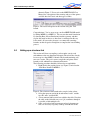
MIKE FLOOD
Modelling of River Flooding
A Step-by-step training guide
DHI Water & Environment
Agern Allé 5
DK-2970 Hørsholm
Denmark
Tel:
Fax:
E-mail:
Web:
+45 4516 9200
+45 4516 9292
[email protected]
www.dhigroup.com
DHI Software 2007
DHI Water & Environment
DHI Software 2007
DHI Water & Environment
CONTENTS
MIKE FLOOD
Modelling of River Flooding
Step-by-step training guide
GETTING STARTED WITH RIVER MODELLING IN MIKE FLOOD................... 3
1
BRIEF INTRODUCTION TO MIKE FLOOD ............................................... 3
2
PURPOSE OF THIS DOCUMENT ................................................................ 3
3
MIKE FLOOD EXAMPLE SETUP................................................................ 4
3.1
3.2
3.3
3.4
Introduction to the example model ..................................................................................... 4
Creating the MIKE FLOOD file for the Example Model setup ........................................... 4
Lateral coupling of rivers to their respective flood plains ................................................... 7
Setting up a structure link................................................................................................... 9
4
THE COMPLETE SETUP............................................................................ 10
i
DHI Water & Environment
ii
DHI Water & Environment
MIKE FLOOD
Brief Introduction to MIKE FLOOD
Getting Started with river modelling in MIKE FLOOD
1
BRIEF INTRODUCTION TO MIKE FLOOD
MIKE FLOOD is a tool that integrates the models MIKE 11, MOUSE
and the MIKE 21 into a single, dynamically coupled modelling
system. Using a coupled approach enables the best features of all
three models to be utilized, while at the same time avoiding some
limitations that may be encountered when using the components
separately.
2
PURPOSE OF THIS DOCUMENT
The purpose of this document is to:
assist the user in understanding the relationships among the model
files and linkage types that make up a MIKE FLOOD river model
simulation data set; and,
provide a step-by-step example of how to set up a basic MIKE
FLOOD floodplain model using existing MIKE 11 and MIKE 21
model data files.
The set-up of a two-dimensional overland model and a onedimensional sewer model is treated separately in the document
“Modelling of Urban Flooding”
A Step-by-step training guide
3
DHI Water & Environment
Modelling of River Flooding
3
MIKE FLOOD EXAMPLE SETUP
3.1
Introduction to the example model
The example model referenced in this document is the “Floodplain
Demonstration” example discussed briefly in the MIKE FLOOD User
Manual, which can be found on your computer after MIKE FLOOD
installation in the sub-folder
“Manuals\MIKE_FLOOD “
of the installation folder typically the installation folder is
“C:\Program Files\DHI\MIKEZero”.
This document is not intended to provide a step-by-step,
comprehensive tutorial on setting up the MIKE 11 and MIKE 21
components of the MIKE FLOOD model. Detailed information on the
creation of new MIKE 11, MOUSE and MIKE 21 models datasets can
be found in their respective software user and reference manuals
included with the software installation. Instead, this document is
intended to discuss the steps required to link a MIKE 11 1dimensional river model a MOUSE sewer model with the MIKE 21 2dimensional floodplain model to create a MIKE FLOOD coupled 1D/2-D floodplain model. It is assumed that the user has a working
understanding of the applicable hydraulic engineering principles and
hydraulic modelling in general before beginning this MIKE FLOOD
example setup.
3.2
Creating the MIKE FLOOD file for the Example Model setup
The procedure below will walk you through the steps to link an
existing MIKE 11 and an existing MIKE 21 model setup thus
constructing an MIKE FLOOD model encompassing the rivers and the
surrounding floodplains. You will create a new MIKE FLOOD
simulation file and add lateral, structure, zero flow and urban links
(described in detail in the MIKE FLOOD User Manual) to accomplish
this. If you wish instead to load the fully linked MIKE FLOOD
simulation coupling file, it can be found in the examples folder of the
installation typically the location
\Examples\MIKE_FLOOD\FloodplainDemonstration
To create the MIKE FLOOD example model from the existing 1D and
2D models do the following:
4
DHI Water & Environment
MIKE FLOOD
MIKE FLOOD example SETUP
1. Start MIKE FLOOD from your computer’s START menu under
Programs!DHI Software!MIKE FLOOD.
2. Create a new MIKE FLOOD simulation file by choosing
File!New!MIKE FLOOD!MIKE FLOOD. Save the MIKE
FLOOD setup file under a name of your choosing in the
examples folder
Examples\MIKE_FLOOD\FloodplainDemonstration
3. Don’t overwrite the existing MIKE FLOOD setup file in the
example files folder.
Figure 1: Selection of MIKE 21 file.
4. Activate the Definition menu item on the left of the MIKE
FLOOD interface.
5. Select the appropriate MIKE 21 simulation files in the
Definition section of the MIKE FLOOD editor (found in the
folder “Surface”).
6. Activate the tick box to activate the MIKE 11 model selection
(see Figure 2).
7. Explore the MIKE 11 model network by clicking on the “Edit
MIKE 11 Input” button in the Definition dialog. To see the
river network, click the Input tab on the resulting dialog box,
then click the “Edit” button beside the item specifying the
“Network” file (Figure 2). Please refer to the MIKE 11 user
manual for information on browsing features and data forms in
the river Network file, the Cross-section file, and other MIKE
11 simulation files.
A Step-by-step training guide
5
DHI Water & Environment
Modelling of River Flooding
Figure 2: Selection of a river set-up. Note the tick box which has been
selected prior to activation of the browse button (the ellipses). Further
the buttons are not active until the tick box has been selected.
8. Explore the MIKE 21 model setup by clicking on the “Edit M21
Input” button. Please refer to the MIKE 21 user manual for a
full description of MIKE 21 model parameters and their
specification.
9. To see the MIKE 21 model grid describing the floodplain
topography select the menu item ‘Basic Parameters !
bathymetry’ and then the view button as shown in Figure 4. To
better visualize the resulting topography in the graphic view
you can choose to generate a new palette. This is done through
the main toolbar through the menu ‘View ! Palette ! new’.
Go through the steps needed in generating palette.
As can be seen the river branches are not defined in great detail in the
topographic grid. The location of the rivers is most clearly visualized
through the MIKE FLOOD interface (a close up is shown in Figure 3).
Figure 3: Close up of the combined river and flood plain model.
6
DHI Water & Environment
MIKE FLOOD
MIKE FLOOD example SETUP
Figure 4: Access to the grid file used to describe the floodplain is
gained through the MIKE 21 interface.
At this point the two main model components have been brought into
the MIKE FLOOD interface. The goal from here on is to couple the
river and the floodplain using the various tools available within the
MIKE FLOOD editor.
3.3
Lateral coupling of rivers to their respective flood plains
The set-up has two branches “River” and “trib”. These will be coupled
along the river banks to the two-dimensional domain to do this the
following steps should be followed.
1. Right click in the graphical view to display a range of tools.
Figure 5: Right clicking in the graphical view.
2. Select the option ‘Link river branch to MIKE 21…’ to display
the linking menu.
A Step-by-step training guide
7
DHI Water & Environment
Modelling of River Flooding
Figure 6: The lateral linkage tool
3. This first link is between the tributary stream and the left over
bank floodplain area of the MIKE 11 river branch called
“TRIB. The linkage extends along the tributary from MIKE 11
chainage 1350.00 meters to chainage 1885.00 meters, and
should join the MIKE 11 reach to a number of grid cells in the
MIKE 21 model. Select the ‘Lateral link’ as the link type.
4. Select a ‘Left’ in the combo box.
5. Specify the river name and the topo ID along with the chainages
of the reach to be coupled.
6. The appropriate cells have now been selected in the grid.
7. The first link entry is empty and should be deleted. This is done
by marking it and then clicking the delete button on the right
(see Figure 7).
Figure 7: Deleting the first non-valid row in the MIKE FLOOD editor.
8. The specific linked cells is specified in the left table named
“M21 Coord 1”. MIKE 21 grid cells are set up in a J and K
coordinate system instead of Northing and Easting, to allow for
rotated grids. In this case, the J direction represents columns in
the grid (which would be X or Easting in a typical map
coordinate system), and the K direction represents rows in the
grid (Y or Northing in a non-rotated grid). The rotation of the
MIKE 21 grid is determined upon initial model setup, and
should generally be oriented so that predominant flow direction
follows either the J or K direction.
9. After you’ve specified where the flooding from MIKE 11
should enter the left-side floodplain, now you need to specify
how flow will be interchanged for this link between MIKE 11
and MIKE 21. So, in the MIKE FLOOD editor, click the
Lateral Link Options section. Set up the lateral link options as
8
DHI Water & Environment
MIKE FLOOD
MIKE FLOOD example SETUP
shown in Figure 5. Please refer to the MIKE FLOOD User
Manual for a description of the meaning and use of the options
available here for Lateral and other types of links.
Figure 8: The lateral ink options for the left link along the ‘Trib’
branch.
Congratulations! You’ve now set up your first MIKE FLOOD model
by linking MIKE 11 to MIKE 21. You can start the model simulation
by choosing Run ! Start Simulation from the top menu, and then
explore the model results to see how flow is exchanged in this very
basic model. All you need to do now is to connect the remaining
branches to their respective floodplains to complete the lateral linking
process.
3.4
Setting up a structure link
This section will focus on coupling a culvert under a major road
embankment to the two-dimensional domain. The culvert has already
been set-up in a short MIKE 11 branch. The branch containing only
two cross section. The goal is now to couple the end points of this
branch to cells within the two-dimensional domain.
The following procedure should be followed to accomplish this.
1. Right click in the graphical view (see Figure 5) and select the
‘Link River Branch to MIKE 21 …’
Figure 9: The selection of the branch end to couple for the culvert
2. Select the upstream end of the branch named ‘culv1’ and the
topo ID ‘struc’ and click OK.
3. A new structure link has now been added to the table. Note that
the table on the left holds one set of (j,k) coordinates though it
is possible to link multiple cells.
4. Since a culvert has both an upstream end and a downstream
end, it is necessary to specify a linkage for both ends of the
A Step-by-step training guide
9
DHI Water & Environment
Modelling of River Flooding
“CULV1” branch to the MIKE 21 grid. The downstream
linkage is set up by repeating the above process and selecting
the ‘downstream end of the branch’.
5. Once again, you have to specify how flow will be interchanged
for these culvert links between MIKE 11 and MIKE 21. In the
MIKE FLOOD editor, click the Standard/Structure Link
Options section. Set up the link options as shown in rows 2
and 3 in Figure 10.
Figure 10: The lateral link options for both ends of the culvert.
Please refer to the MIKE FLOOD User Manual for a description of the
meaning and use of the options available here for Structure and other
types of links. Since these culvert links are Structure type links, there
is no information to fill in on the Lateral Link Options section of the
MIKE FLOOD Editor.
You can now run the simulation again, to see what effect adding the
culvert has, by choosing Run ! Start Simulation from the top menu.
4
THE COMPLETE SETUP
Now that you’ve created your own basic MIKE FLOOD model, with
two of the most common link types, you may want to explore an
expanded version of this same model area by opening the original
example. The larger model includes several more links, including
lateral links for the left and right overbanks of both the tributary
branch “TRIB” and the main river branch “RIVER” and a second
culvert called “CULV2”. This example file also includes two zeroflow linkages, which are here used to prevent flows from crossing
from one side of a river to the other side in MIKE 21 without first
passing through the MIKE 11 river channel network.
You can read more about zero-flow links and also the Standard link
type, and find detailed descriptions of the linkage options available in
MIKE FLOOD, in the MIKE FLOOD User Manual.
10
DHI Water & Environment
MIKE FLOOD