1
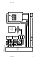
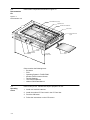
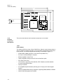
Cobra VG330 Single-Chip
Hardware Reference Platform
Technical Manual
Cobra VG330 Single-Chip
Hardware Reference Platform
Technical Manual
Document No. RM230001-02
Copyright 1996 Vadem
All Rights Reserved
Information furnished by Vadem is believed to be accurate and reliable. However, no responsibility is
assumed by Vadem for its use; nor for any infringements of patents or other rights of third parties which
may result from its use. No license is granted by implication or otherwise under any patent or patent rights
of Vadem. Vadem reserves the right to change specifications at any time without notice.
Trademarks mentioned herein belong to their respective companies.
Medical Disclaimer
Vadem’s products are not authorized for use in life support devices or systems or in any medical applications and cannot be used in such applications without the written consent of the President of Vadem.
ii
Preface
This manual is the primary reference and user’s guide for the Vadem Cobra
VG-330 Single-Chip Hardware Reference Platform, commonly referred to as
Cobra in this manual.
Audience
This document assumes that you have some familiarity with personal computers, microprocessors, and related support devices. The people who benefit from this book are:
♦ Managers and engineers who are considering the use of Cobra in a portable design.
Related Publications
VG330 Product Data Manual—DM330001
VG330 OEM BIOS Specification—DM330002
VG330EVAL Evaluation Kit User’s Manual—DM330003
VG330ADPT BIOS Adaptation Kit Data Manual—DM330004
VG330 Debugger Utility User’s Manual—DM330005
VG330 Configuration Utility User’s Manual—DM330006
VG330 Product Functional Description—FD330001
VG330ICE In-Circuit Emulator Product Brief—PB330001
VG330BIOS Single-Chip Firmware Product Brief—PB330002
VG330EVAL Evaluation Board Product Brief—PB330003
VG330 Single-Chip Platform Product Brief—PB330004
VG330ADPT BIOS Adaptation Kit Product Brief—PB330005
VG330 Power Management White Paper—WP330001
Cobra Software User’s Guide
Preface
iii
Conventions Used in
This Manual
The first time a word or phrase is defined in this manual, it is italicized.
The following signal naming conventions are used throughout this manual:
♦ A level-significant signal that is true or valid when the signal is LOW is
preceded with an asterisk (*) or slash (/).
♦ An edge-significant signal that initiates actions on a HIGH-to-LOW transition is preceded with an asterisk (*) or slash (/).
The word assert means to drive a signal true or active. The word deassert
means to drive a signal false or inactive.
Hexadecimal numbers are indicated by the suffix “h”— for example 0Ah.
Binary numbers are indicated by a subscripted “2” following the number—for
example, 0011.0010.1100.11112.
iv
Preface
Contents
1.1
1.2
1.3
1.4
1.5
1.6
1.7
1.8
1.9
Introduction
Features
System Architecture
Design Objectives
Block Diagram
Demonstration Kit
Operating Cobra
Hardware Description
1.8.1
Printed Circuit Board (PCB)
1.8.2
Hardware Component Descriptions
Bill of Material
1-1
1-2
1-3
1-4
1-4
1-6
1-6
1-7
1-7
1-8
1-15
Figures
1.1
1.2
1.3
1.4
1.5
1.6
1.7
1.8
Cobra Block Diagram
Demonstration Unit
Cobra PCB (top)
Cobra PCB (bottom).
VG330 Block Diagram
MAX148 A/D Converter Block Diagram
Digitizer Electronics
LCD Block Diagram
1-5
1-6
1-7
1-8
1-9
1-11
1-13
1-14
Tables
1.1
1.2
1.3
1.4
Touch Panel Specifications
Switch States for Digitizer
LCD Specifications
Bill of Material
1-12
1-13
1-14
1-15
Contents
v
vi
Contents
Cobra VG330 Single-Chip
Hardware Reference Platform
This document describes an application of Vadem’s technology capabilities to a portable, low-power system, the Cobra VG330 Single-Chip Hardware Reference
Platform, commonly referred to in this document as Cobra.
1.1
Introduction
Vadem provides enabling technology for hand-held electronic data processing products. It has expertise in single-chip microcomputers and power-management for lowpower handheld products. Vadem has designed a custom, low-power single-chip
solution for OEMs wishing to create battery-efficient handheld systems. This can
reduce the time-to-market for creation of new leading-edge portable data products.
Vadem’s technological knowledge, backed by experience and numerous successful
designs, can help you quickly bring to market low power, highly integrated competitive products. Vadem can provide you with the tools needed to enter a market fast.
Cobra is only one example of many different solutions, applications, and operating
systems which can be built on Vadem’s single-chip platforms.
Introduction
1-1
1.2
Features
Cobra has the following features:
♦ Vadem VG330 single-chip PC platform
♦ A total of 2 MByte of DRAM consisting of a single 1M x 16 DRAM
♦ 4 MBytes of FLASH EPROM, consisting of two 1M x 16 FLASH devices
♦ Power Supply Unit
♦ LCD display
♦ Digitizer/touch panel using 10-bit serial A/D converter
♦ VG330 Firmware/BIOS
♦ Graphical OS Software & Applications
♦ PC Card Slot
♦ Enclosure and hardware
♦ Infra-red communications transceiver
1-2
1.3
System
Architecture
Vadem' s approach for Cobra was to develop a small, handheld client device to provide email, web browsing, and general interconnectivity with few device resources.
Cobra contains bundled firmware and application software, allowing a “plug ‘n play”
solution for internet and world-wide-web access.
The application software consists of:
♦ HTML 2.0-compatible Web Browser
♦ E-mail
♦ Usenet
You can customize Cobra with an API for lower-level firmware and use standard
development tools based on DOS to develop your own applications. This toolkit
approach of a well-documented API plus standard DOS development tools allows
easy application development for the OEM consumer. The standard software development tools allow you to compile, assemble, link, locate, and debug using DOS.
You can link into the libraries provided by Vadem, form an executable file for the
VG330, and put the image into ROM.
A version of the kernel can run on top of DOS, so while you are prototyping, you
can develop all the applications for DOS, and prototype with them. After you have
finished debugging, you can use the same API that you use on the kernel, then use
the new kernel libraries that do not have DOS function calls to eliminate the overhead associated with DOS.
System Architecture
1-3
1.4
Design
Objectives
Cobra was developed with two specific objectives:
♦ Provide OEM developers with full schematics and documentation for a working
design
♦ Show that a working device can be built, using 2-AA batteries, in a most compact
design, with a low bill of materials costs
Cobra can be used as a baseline development architecture for a system running the
an operating system that allows hardware management as well as connection to an
internet mediation server.
Cobra highlights the power, size and integration capabilities of Vadem’s low cost single-chip processors, and demonstrates how easy it is to build a light weight, portable,
pen-based personal information manager using Vadem technology.
Cobra combines the state-of-the-art technologies of Vadem’s VG330 single chip computer with a PC Card and a Graphical User Interface (GUI) with pen input. It shows
how easy it can be to create a PDA (Personal Digital Assistant), a PIM (Personal Information Manager), a PDT (Portable Data Terminal), or a general purpose Electronic
Organizer. The system demonstrates that a design can achieve powerful functionality
while retaining the low cost and low power requirements for hand-held devices.
Cobra uses a pen-input, graphical user interface (GUI) based operating system
together with Vadem firmware. The system runs applications such as a web browser,
graphical e-mail, and usenet.
Vadem’s objective for this design is to demonstrate the ability to build a light weight,
cost-effective, personal information manager running on two AA batteries. Vadem’s
patented power management technology and system level integration are among the
critical factors that contribute to the design’s success.
Cobra is provided with a generic case; however, OEMs are free to choose their own
case design. There are few ICs required on the board because most of the system
level components are already integrated into Vadem’s VG330. As a result, the design
achieves reduced power consumption and compact size.
Cobra demonstrates Vadem’s ability to design a product with increased levels of functionality, while maintaining the low cost and low power consumption requirements for
hand-held devices.
1.5
Block Diagram
1-4
Figure 1.1 is a high-level Cobra block diagram.
VG330
Single-Chip
Platform
Block Diagram
Transceiver
Buffer/
Latch
Buffer
D[15:0]
A[23:0]
RD/WR/EN
DRAM
(2 MB)
FLASH
EPROM
(4 MB)
IR Rx Data
IR Tx Data
Infra-red
Transceiver
Digitizer Control Signals
Digitizer Serial Data
LCD Panel Data and Control
D[15:0]
A[20:0]
FLASH
Programmer
RD/WR/EN
A[23:0]
A[20:0]
Figure 1.1
Cobra Block Diagram
PC Card
Connector
PC Card
PCMCIA 2.1
(JEIDA 4.1)
Compatible
MAX148
A/D Converter
Remote Device
Infra-red
Transceiver
Digitizer Pad
LCD Panel (320x240)
Draft 11/14/96
1-5
1.6
Demonstration
Kit
Cobra’s main components are shown in Figure 1.2.
Figure 1.2
Demonstration Unit
Main Batteries (2-AA)
Digitizer Pad
Printed Circuit Board
4.5"
LCD Panel
External Power
Input
1.25"
Backup
Battery
Reset
Switch
On/Off
Switch
Infra-Red
Transceiver
5.5"
Cobra contains the following items:
•
•
•
•
•
•
•
1.7
Operating
Cobra
Enclosure
PCB
Operating System in FLASH ROM
Modem Card for Internet Access
Two AA Batteries
This Technical Manual
Vadem VG330 Data Manual
Cobra is easy to use. Follow these steps to prepare it for use:
1. Install two fresh AA batteries.
2. Install the modem PC Card card in the PC Card slot.
3. Push the ON button.
4. Follow the instructions on the LCD screen.
1-6
Modem
Card
1.8
Hardware
Description
Cobra includes a PCB with its components and a small form factor digitizer tablet
overlaid on an LCD. The LCD/Digitizer can be replaced by an LCD/Digitizer of the
customer’s own choosing, allowing any size to be considered.
1.8.1
Printed Circuit
Board (PCB)
The Cobra PCB contains the following principal hardware elements, as shown in
Figure 1.3 and Figure 1.4.
•
•
•
•
•
•
•
•
Vadem VG330 single-chip PC platform
2 MByte of DRAM
4 MBytes of FLASH memory configured as two 1M x 16 flash ROMs,
Power Supply Unit
LCD display
Digitizer/touch panel using 10-bit A/D converter
VG330 Firmware/BIOS
PC Card Slot
Figure 1.3
Cobra PCB (top)
3.0"
U24
LM393
U6
MAX148
U10
74HC191
U23
MAX749
U14
74LVT125
U26
U21
74HCT00
U9
74LV14
U4
74LVT244
0.5"
U13
74LV08
U15
TPS1120
U22
MAX756
2.0"
U17
FLASH EPROM
U1
74LVT16245
Hardware Description
U8
74LVT16373
1-7
Figure 1.4
Cobra PCB (bottom).
3.0"
0.5"
P2 PCMCIA Connector
U2
LVT16245
P28
Digitizer
Connector
U11
DRAM
U18
FLASH EPROM
U3
LVT244A
2.0"
U12
VG330
2.375"
Power
Supply
U5
HCT244
1.8.2
Hardware
Component
Descriptions
This section describes the main hardware components in more detail.
1.8.2.1
Vadem VG330
The Vadem VG330 is a single 160-pin CMOS chip. Vadem’s custom design makes it
easy for OEMs to develop low-power, yet cost-sensitive, DOS-based personal electronic products. The VG330 integrates the following, as illustrated in Figure 1.5.
1-8
•
32-MHz NEC V30MX processor (16-bit, 80186-compatible CPU)
•
PC Card 2.10/ExCA/JEIDA 4.2 controller
•
8254-compatible Counter/Timer
•
16450-compatible serial port with HP infra-red interface option
•
RTC (Real-Time Clock)
•
LCD controller, supporting CGA 640x200, AT&T 640x400, and VGA 640x480
monochrome graphics modes
•
Interrupt Controller
•
XT-compatible keyboard interface (scanning up to 101 keys) and a matrix keypad
scanner
•
LIM 4.0-compatible EMS memory subsystem, supporting DRAM, SRAM, or PSRAM
•
Vadem Power Management Unit (PMU)
•
24 GPIO (General-Purpose I/O) pins, for flexible configuration of inputs and outputs
•
ISA Bus controller, capable of 8- and 16-bit memory and I/O cycles, similar to PCAT bus cycles
•
Bus Cycle Generator, which controls all timing
•
Bus Interface Unit, controlling external ISA bus and internal address and data
path handling
Figure 1.5
VG330 Block Diagram
Power
Management
Unit
System
Clocks
Interrupt
Controller
Unit
Memory
Controller
MC[9:0]
Real-Time
Clock
NEC
Counter/
Timer
V30MX
CPU
A[23:0]
Bus Cycle
Generator
ISA Bus
Controller
Bus Interface
Unit
D15:0]
Serial I/O
GeneralPurpose I/O
Keyboard Control
Unit
LCD
Controller
PC Card
Controller
1.8.2.2
Memory
The Cobra demonstration unit contains 2 Mbytes of DRAM, shown on sheet 4 of the
schematic. The DRAM addressing conforms to the Memory Controller Pin Functions
table in Chapter 6, “Memory Controller Unit,” of the VG330 Data Manual.
DRAM Memory – Memory control lines MC6 and MC7 control /LCAS and /UCAS,
while MC8 and MC9 control /OE and /WE. The bank selection is done by MC0, which
is connected to the /RAS pin of the DRAM.
FLASH ROM Memory – The ROM memory in the demo unit consists of two 1Mx16
FLASH ROMs, for a total of 4 Mbytes. /SMRD is used to control /OE for both ROMs.
The two are addressed by setting either /ROMEN active or /ROMCE1 active. Designers may choose to use other ROM sizes. A design may use only one ROM bank
accessed by /ROMEN, if required, in which case /ROMCE1 would go unused.
1.8.2.3
PCMCIA
Cobra has one card slot that complies with PC Card 2.10 (JEIDA 4.1) standards. This
is shown on sheet 5 of the schematic.
Hardware Description
1-9
1.8.2.4
Infrared Communication (IrDA)
For purposes of illustration, Cobra includes components to show how infrared communication can be easily included in a design, but software drivers are not included at
this time with the hardware.
Cobra uses Temic’s TFDS3000 Infrared IrDA Integrated Transceiver Circuit, which is
connected to the VG330’s serial port IR_RXD and IR_TXD signals. The IR_RXD and
IR_TXD signals are two of the VG330’s GPIO (General Purpose Input/Output) pins.
Temic’s TFDS3000 IrDA Integrated Transceiver connects to the VG330 and contains
an integrated photo-diode and LED. The transceiver RXD output is inverted before
being sent to the VG330 as IR_RXD, and the VG330 IR_TXD signal is fed through a
tri-state buffer before being sent to the transceiver as TXD. The TFDS3000 transmits
and receives the pulse shaped bit stream and can be shut down for power management under control of the VG330 /IRDA_EN signal.
The IrDA standard allows data rates from 2.4kBaud up to 115kBaud.
1.8.2.5
A/D Converter
Cobra uses Maxim’s MAX148, a 10-bit serial Analog-to-Digital Converter with an internal Track/Hold and a sampling rate of 133KHz. The converter is shown on sheet 7 of
the schematic, and shown in Figure 1.6.
The device can be used in 8-channel single-ended mode, or 4-channel differential
mode. The present Cobra design uses single-ended mode. An auto-calibration cycle
eliminates need for offset or gain adjustment. Conversion results are available through
a serial output.
1-10
Figure 1.6
MAX148 A/D Converter Block
Diagram
CS
SCLK
DIN
SHDN
CH0
CH1
CH2
CH3
CH4
CH5
CH6
CH7
18
19
17
Input
Shift
Register
Control
Logic
10
1
2
3
4
5
6
7
8
Internal
Clock
Output
Shift
Register
Analog
Input
Mux
T/H
Clock
15
16
12,20
In
COM
9
10 + 2-bit
SAR
ADC
Out
14
13
DOUT
SSTRB
VDD
DGND
AGND
Ref
VREF
(2.500V)
11
Hardware Description
1-11
1.8.2.6
Touch Panel
The demonstration unit uses a GUNZE G-20 (resistive touch panel) digitizer. It works
in conjunction with custom pen driver software to display digital ink on the LCD display. The performance specifications are listed in Table 1.1.
Table 1.1
Touch Panel
Specifications
Electrical
Parameter
Value
Maximum voltage
5 VDC.
Maximum current
Less than 1 mA at contact point of top layer with bottom layer
Operating temperature
0 °C to 50 °C
Operating Humidity
20% to 85% (non-condensing)
Non-Operating
temperature
-10 °C to 60 °C
Non-Operating humidity
20% to 90% (non-condensing)
Terminal resistance
between XL and XR: 250 to 760 ohms
between YU and YL: 250 to 760 ohms
Linearity
+/- 1%
Insulation resistance
10 megohm or more at 26 VDC
Input
Actuation force
Transparency
Surface hardness
Mechanical
±0.8 stylus or finger
10 - 80 grams
Typical 78%
Pencil hardness 3H or more according to IIS-K6400
The touch panel operates by producing an X axis and a Y axis resistance value that
corresponds to where the pen is pressed. These values are read by passing a voltage
through the panel on each axis and measuring the output voltage for that axis. Refer
to Figure 1.7.
Refer to sheet 7 of the schematic for details of the MOSFET switches used in this
design. Switch Control signals SWCTRL[2:0] open and close the MOSFETs, Q1-Q4,
shown on that sheet and in Table 1.2.
The digitizer output is read as follows: hardware detection of pen-down causes the
firmware to control reading of one digitizer axis at a time. For example, the Y-axis
value is read by turning Q1 and Q3 on to provide a voltage across the Y axis of the
digitizer sheet. Analog voltage CH1 is buffered and sent to an input of the A to D converter, where it is converted to a digitized value.
Designers may use their own choice of vendor for the Digitizer Panel.
1-12
Figure 1.7
Digitizer Electronics
+3.3V Main
R21
150
R20
150
U9
74LV14
9
SWCTRL0
To
A/D Converter
8
3
Q2
CH0
R17 100
2
2
1
1
3
Q1
VSENSE*
Q1 and Q2 are
P-Channel MOSFETs
CH1
R22 100
X1
Y1
Digitizer
X2
Q4
SWCTRL1
3
Y2
1
1
2
2
Q3 and Q4 are
N-Channel MOSFETs
Q3
3
SWCTRL2
R24
50
GND
R23
50
GND
* The VSENSE signal is used for detecting pen-down (see schematic page 7)
Table 1.2
Switch States for Digitizer
Switch State
State
Q1
Q2
Q3
Q4
Closed
Open
Open
Open
Pen-down, scan X
(A/D converter reads CH0)
Open
Closed
Open
Closed
Pen-down, Scan Y
(A/D converter reads CH1)
Closed
Open
Closed
Open
Waiting for pen-down
Hardware Description
1-13
1.8.2.7
Liquid Crystal Display
The LCD used is a Sharp LM320081 passive matrix LCD. It has an integrated decoder
for the external 4-bit parallel data bus and has the following basic specifications:
Table 1.3
LCD
Specifications
Parameter
Value
Dot size
Dot pitch
Pixel Resolution
Active viewing area
.28 mm
.30 mm
320 dots W x 240 dots H
100W x 76H (mm)
Figure 1.8
LCD Block Diagram
FRAME
320
COM driver
LCD
320x240 Dots
240
LOCLK,SHCLK
SEG driver
LCD[3:0]
VCC_LCD
VSS
BIAS circuit
VEE
1-14
Note: Vadem chose the Sharp LCD used in the demonstration unit for size, quality
and availability. Designers may of course select their own choice of vendor for the
LCD Panel. Samsung’s UG32F07FNBRX-A panel is a low cost alternative
1.8.2.8
Power Supply
Main power to Cobra comes from two AA batteries. A Maxim MAX756 device steps
up the battery voltage to 3.3V, which powers most of Cobra’s electronics. A Maxim
MAX777 device provides +5V to run the LCD panel and PCMCIA card. A MAX858
device provides 3.3V from the lithium backup battery to maintain the system configuration information while the AA batteries are being changed.
The Power Management Unit (PMU) of the VG330 supplies signals for controlling
power to the ROM, LCD and PCMCIA card. These switches are implemented using a
TPS1120D MOSFET switch.
1.9
Bill of Materials
The bill of materials for Cobra is shown in Table 1.4
Table 1.4
Bill of Materials
Item
Quantity
1
2
1
39
3
4
5
6
7
8
9
10
11
12
13
14
15
16
17
18
19
20
21
22
23
24
3
1
1
2
4
2
1
1
2
1
1
1
1
1
3
2
2
2
1
1
1
1
Reference
Part Description
D6
C1, C2, C3, C5, C6, C7, C9, C10, Cl1, C12,
C13, C14, C15, C17, C18, C20, C21, C22,
C23, C24, C25, C26, C27, C28, C31, C32,
C35, C36, C38, C44, C45, C46, C47, C48,
C50, C53, C56, C57, C58
C4, C8, C43
C16
Cl9
C29, C30
C33, C34, C51, C54
C40, C37
C39
C41
C42, C49
C52
C55
D1
D2
D3
D4, D5, U20
JP5, JP1,JP9
JP3, JP2
JP4, JP10
JP7
JP8
L1
L2
1N4148
0.l uF
Bill of Materials
l00 pF
0.00l uF
470 pF
15 pF
l00 uF
22 pF
0.0033 uF
150 uF
22 uF
0.0l uF
6.8 uF
12V
lN5818
IN5817
lN914
HEADER 12
2-W
HEADER 2
HEADER 5
3-W
4.7 uH
l0 uH
1-15
Table 1.4
Bill of Materials
1-16
Item
25
26
27
28
29
30
31
32
33
Quantity
1
2
1
1
2
3
1
1
20
34
35
2
15
36
37
38
39
40
41
42
43
44
45
46
47
48
49
50
51
52
53
54
55
56
57
58
59
60
61
62
63
64
65
66
67
68
69
70
3
1
2
2
2
2
1
1
1
4
1
1
1
2
1
2
1
1
1
1
1
1
1
2
1
1
1
1
1
1
1
2
1
1
1
Reference
L3
L4, L5
P1
P2
Q2, Q1
Q3, Q4, Q6
Q5
Q7
R1, R2, R3, R6, R9, R10, R12, R13, R14, R18,
Rl9, R25, R37, R70, R71, R72, R75,
R76,R777,R78
R4, R39
R5, R11, R16, R26, R27, R29, R35, R36, R38,
R40, R44, R59, R61, R62, R63
R7, R48, R74
R15
R17, R22
R20, R21
R23, R24
R28, R54
R32
R34
R41
R42, R43, R45, R50
R46
R47
R49
R69, R51
R53
R65, R56
R57
R58
R60
R66
R67
R68
R73
TP2, TP1
TP3
U1
U2
U3
U4
U5
U6
U25, U7
U8
U9
U10
Part Description
22 uH
47 uH
DIGITIZER
PCMCIA
BSS84ZXCT-ND
ZVN3310FCT-ND
PMBT2222A
ZTX750
22K
100K
47K
1M
220
100
150
50
10K
10 ohm
12K
450K
100K 1%
4.3K
1.64M
470
100 OHM
470K 1%
1M 1%
0.5
43K 1%
3K
600K 1%
4.7 OHM
2K
lM 1%
TP
TP
74LVT16245
74LVT16244
74HC244
74LVT244
74HCT244
MAX148
MAX811
74LVT16373
74LV14
74HC191
Table 1.4
Bill of Materials
Item
71
72
73
74
75
76
77
78
79
80
81
82
83
84
85
86
Quantity
1
1
1
1
1
2
1
1
1
1
1
1
1
1
1
1
Reference
U11
U12
U13
U14
U15
U17, U18
U19
U21
U22
U23
U24
U26
U27
U28
Y1
Y2
Bill of Materials
Part Description
M5M4V18160BTP
VG-330
74LV08
74LVT125
TPS1120D
LH28F016SU
MAX777
74HCT00
MAX756
MAX749
LM393
MAX858
TFDS3000
TPS1120
32.768 KHz
32 MHz
1-17
1-18