1
I-7565-H1 / I-7565-H2
High Speed USB/CAN Converter
User’s Manual
Warranty
All products manufactured by ICP DAS are under warranty regarding
defective materials for a period of one year from the date of delivery to the
original purchaser.
Warning
ICP DAS assumes no liability for damages resulting from the use of
this product. ICP DAS reserves the right to change this manual at any time
without notice. The information furnished by ICP DAS is believed to be
accurate and reliable. However, no responsibility is assumed by ICP DAS
for its use, or for any infringements of patents or other rights of third
parties resulting from its use.
Copyright
Copyright 2009 by ICP DAS. All rights are reserved.
Trademark
The names used for identification only may be registered trademarks
of their respective companies.
I-7565-H1/H2 High Speed USB/CAN Converter User’s Manual (Ver 1.1, Nov/2009) ------------- 1
Table of Contents
1. Introduction ........................................................................................4
1.1
1.2
Features............................................................................................. 5
Specifications ..................................................................................... 5
2. Hardware.............................................................................................7
2.1
2.2
2.3
2.4
2.5
2.6
Block Diagram.................................................................................... 7
Pin Assignment of CAN Port .............................................................. 8
Hardware Connection ........................................................................ 8
Terminator Resistor Settings ............................................................ 10
Init / Normal Dip-switch .....................................................................11
Firmware Update Mode...................................................................11
Firmware Operation Mode.............................................................. 12
LED Indication.................................................................................. 14
2.7
Cable Selection................................................................................ 15
2.5.1
2.5.2
3. Driver Installation .............................................................................17
3.1
3.2
3.3
Install I-7565-H1/H2 Driver:.............................................................. 17
Verify Driver Installation: .................................................................. 20
Uninstall I-7565-H1/H2 Driver .......................................................... 21
4. Software Utility .................................................................................22
4.1
4.2
4.3
4.4
4.4.1
4.4.2
4.5
4.6
INI File Function............................................................................... 22
Connection Function ........................................................................ 22
Communication Function ................................................................. 24
Config Function................................................................................ 26
Module Config Function ................................................................. 27
Advanced Config Function ............................................................. 30
Data Log Function............................................................................ 31
Status Bar Function.......................................................................... 33
5. API Library -- VCI_CAN.dll...............................................................35
5.1
5.2
5.3
5.4
5.4.1
5.4.2
5.5
5.5.1
5.5.2
API Library Overview ....................................................................... 35
API Library Function Table ............................................................... 36
Flow Chart for Users’ Program Development by Using API ............. 38
Init Function ..................................................................................... 39
VCI_OpenCAN............................................................................... 39
VCI_CloseCAN .............................................................................. 41
Module Config Function ................................................................... 42
VCI_Set_CANFID .......................................................................... 42
VCI_Get_CANFID .......................................................................... 44
I-7565-H1/H2 High Speed USB/CAN Converter User’s Manual (Ver 1.1, Nov/2009) ------------- 2
5.5.3
5.5.4
5.5.5
5.5.6
5.6
5.6.1
5.6.2
5.6.3
5.6.4
5.7
5.7.1
5.7.2
5.7.3
5.8
5.8.1
5.8.2
5.9
VCI_Get_CANStatus ...................................................................... 46
VCI_Clr_BufOverflowLED .............................................................. 47
VCI_Get_MODInfo ......................................................................... 48
VCI_Rst_MOD ............................................................................... 49
Communication Function ................................................................. 50
VCI_SendCANMsg ........................................................................ 50
VCI_RecvCANMsg......................................................................... 52
VCI_EnableHWCyclicTxMsg.......................................................... 54
VCI_DisableHWCyclicTxMsg ......................................................... 56
Software Buffer Function.................................................................. 57
VCI_Get_RxMsgCnt....................................................................... 57
VCI_Get_RxMsgBufIsFull .............................................................. 58
VCI_Clr_RxMsgBuf ........................................................................ 59
Other Function ................................................................................. 60
VCI_Get_DllVer.............................................................................. 60
VCI_DoEvents................................................................................ 61
Return Code..................................................................................... 62
6. Troubleshooting ...............................................................................63
6.1
6.2
6.3
6.4
6.5
6.6
6.7
6.8
6.9
6.10
The Connection Issue ...................................................................... 63
The CAN Baud Rate Issue............................................................... 64
The Same CAN-ID Conflict Issue..................................................... 66
The PC Rebooting Issue .................................................................. 66
The Max Data Transfer Rate (fps) Issue .......................................... 66
The Data Loss Issue ........................................................................ 66
The Module Number Applied to One PC Issue ................................ 67
The Long Driver Installation Time Issue ........................................... 67
The Supported CAN Filter-ID Number Issue.................................... 68
Other Issue ...................................................................................... 69
7. History of Version ............................................................................70
I-7565-H1/H2 High Speed USB/CAN Converter User’s Manual (Ver 1.1, Nov/2009) ------------- 3
1. Introduction
I-7565-H1 and I-7565-H2 are the high speed intelligent USB to CAN
converters with one and two CAN channels separately. They provide
faster CAN bus communication performance than I-7565. Both I-7565-H1
and I-7565-H2 support CAN2.0A/2.0B protocol and different baud rates
from 5 Kbps to 1 Mbps. The important feature of I-7565-H1/H2 is to
support the user-defined baud rate function no matter what the baud rate
is. When connecting I-7565-H1/H2 to PC, PC will load the relevant device
driver automatically (hot plug & play). Therefore, users can make data
collection and processing of CAN bus network easier and quicker by
applying I-7565-H1/H2. The application fields can be CAN bus monitoring,
building automation, remote data acquisition, environment control and
monitoring, laboratory equipment & research, factory automation, etc.
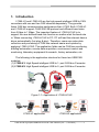
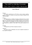
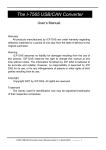
The following is the application structure for these two USB/CAN
modules :
(1) I-7565-H1: High Speed intelligent USB to 1- port CAN bus Converter.
(2) I-7565-H2: High Speed intelligent USB to 2- port CAN bus Converter.
Figure 1-1: Application of I-7565-H1/H2
I-7565-H1 application
I-7565-H2 application
I-7565-H1/H2 High Speed USB/CAN Converter User’s Manual (Ver 1.1, Nov/2009) ------------- 4
1.1
•
•
•
•
•
•
•
•
•
•
•
•
•
•
•
•
•
•
Features
RoHS Design
Fully compliant with USB 1.1/2.0 (Full Speed)
Fully compatible with the ISO 11898-2 standard
Support both CAN2.0A and CAN2.0B
No external power supply (powered by USB)
Integrated with one or two CAN bus interface
Programmable CAN bus baud rate from 5Kbps to 1Mbps or userdefined baud rate
Support CAN bus acceptance filter configuration
Timestamp of CAN message with at least ±1ms precision
Support firmware update via USB
Provide utility tool for users module setting and CAN bus
communication testing conveniently
Provide API library for user program development
Provide PWR / RUN / ERR indication LED
Built-in jumper to select 120 ohm terminal resister
Max data flow for CAN channel: 3000 fps ( depends on users’ PC
hardware performance )
The CAN buffer is 256 data frames for I-7565-H1 and 128 data frames
in each CAN port for I-7565-H2.
Watchdog inside
Driver supported for Windows 2000/XP and WinCE (available soon)
1.2
Specifications
[ USB specs: ]
• Input port : USB (USB Type B)
• Compatibility : USB 1.1 and 2.0 standard
• Driver Supported : Windows 2000/XP and WinCE (available soon)
[ CAN specs: ]
• CAN interface connector:
I-7565-H1 : 9-pin D-sub male
I-7565-H2 : 10-pin terminal-block
• CAN Baud Rate : 5K ~ 1Mbps or User-defined baud rate
• Isolation Voltage : 3000Vrms on the CAN side
I-7565-H1/H2 High Speed USB/CAN Converter User’s Manual (Ver 1.1, Nov/2009) ------------- 5
[ Module specs: ]
• Dimensions : 108mm x 72mm x 35mm (H x W x D)
• Operating temperature : -25 to 75ºC (-13 to 167ºF);
• Storage temperature : -40 to 80ºC (-40 to 176ºF);
• Humidity : 5 to 95%, non-condensing;
• LEDs : PWR LED for power
RUN LED for communication
ERR LED for error
[ Software Utility Tool / API Library: ]
• Provide CAN bus user-defined baud rate / acceptance filter
configuration
• Easily transmit / receive CAN messages for testing and display the
time-stamp of each received CAN message.
• Provide saving the CAN message as “TXT” file for data log.
• Provide sending CAN message by using the internal timer of module
for high precision transmission.
• Check / Reset module status remotely and get current CAN bus
message flow.
• Users can develop own program by API library quickly and easily.
[ Application: ]
• Factory Automation;
• Building Automation;
• Home Automation;
• Control system;
• Monitor system;
• Vehicle Automation;
I-7565-H1/H2 High Speed USB/CAN Converter User’s Manual (Ver 1.1, Nov/2009) ------------- 6
2. Hardware
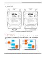
Figure 2-1: Hardware externals of I-7565-H1/H2
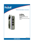
2.1 Block Diagram
Figure 2-2 is a block diagram illustrating the functions on the I-7565H1/H2 module. It provides the 3000Vrms Isolation in the CAN interface
site.
Figure 2-2: Block diagram of I-7565-H1 / I-7565-H2
I-7565-H1/H2 High Speed USB/CAN Converter User’s Manual (Ver 1.1, Nov/2009) ------------- 7
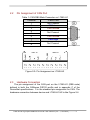
2.2
Pin Assignment of CAN Port
Table 1: CAN DB9 Male Connector on I-7565-H1
Terminal
2-wire CAN
1
Not Connect
2
CAN Low
3
CAN Ground
4
Not Connect
5
6
CAN Ground
7
CAN High
8
Not Connect
9
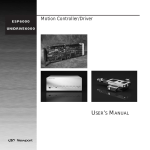
Figure 2-3: Pin Assignment on I-7565-H2
2.3
Hardware Connection
The pin assignment of the CAN port on the I-7565-H1 (DB9 male)
defined in both the CANopen DS102 profile and in appendix C of the
DeviceNet specifications. It is the standard pin assignment for CAN. The
hardware connection between device and I-7565-H1/H2 is like Figure 2-4.
I-7565-H1/H2 High Speed USB/CAN Converter User’s Manual (Ver 1.1, Nov/2009) ------------- 8
Figure 2-4: CAN Hardware Wire Connection
I-7565-H1/H2 High Speed USB/CAN Converter User’s Manual (Ver 1.1, Nov/2009) ------------- 9
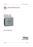
2.4
Terminator Resistor Settings
According to the ISO 11898 specifications, the CAN Bus network
must be terminated by two terminal resistors (120Ω) for proper operation,
as shown in the below figure.
Figure 2-6: Terminal Resistor
Therefore, the I-7565-H1/H2 module supplies a jumper for users to
active the terminal resistor or not. If users want to use this terminal resistor,
please open the I-7565-H1/H2 cover and use the JP3 for I-7565-H1 / JP3,
JP4 for I-7565-H2 to activate the 120Ω terminal resistor built in the module,
as the Figure 2-7. Note that the default setting is active.
Figure 2-7: Terminal Resistor Jumper
Enable (default), (Position: 1-2)
Disable, (Position: 2-3)
Figure 2-8: JP3/JP4 Jumper Position
I-7565-H1/H2 High Speed USB/CAN Converter User’s Manual (Ver 1.1, Nov/2009) ------------- 10
2.5
Init / Normal Dip-switch
On the back of the I-7565-H1/H2 module, there is a dip-switch used
for firmware operation or firmware updating of the module. The following
steps show how to use this dip-switch.
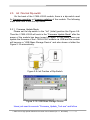
2.5.1 Firmware Update Mode
Please set the dip-switch to the “Init” (Initial) position like Figure 2-9.
Then the I-7565-H1/H2 will work in the “Firmware Update Mode” after the
power of the module has been turned on again. In this mode, users can
update the firmware of the I-7565-H1/H2 module via USB and the module
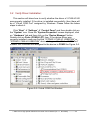
will become a “USB Mass Storage Device” and also shows a folder like
Figure 2-10 automatically.
Figure 2-9: Init Position of Dip-Switch
Figure 2-10: USB Mass Storage Device
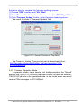
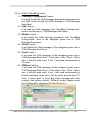
Users just need to execute “Firmware_Update_Tool.exe” and follow
I-7565-H1/H2 High Speed USB/CAN Converter User’s Manual (Ver 1.1, Nov/2009) ------------- 11
the below steps to complete the firmware updating process.
[1] Choose “USB” interface and “USB Disk”.
[2] Click “Browser” button to choose firmware file. (like I7565H1_v1.01.fw)
[3] Click “Firmware Update” button to start firmware updating process.
The result will show in “Firmware Update” field.
Figure 2-11: Normal Position of Dip-Switch
The Firmware_Update_Tool program can be downloaded from
http://ftp.icpdas.com/pub/cd/fieldbus_cd/can/converter/i-7565h1h2/software/tool
2.5.2 Firmware Operation Mode
In operation mode, users need to set the dip-switch to the “Normal”
position like Figure 2-12 and turn the power off then on again so that the I7565-H1/H2 can run in the operation mode. In this mode, users can send /
receive CAN messages via PC USB port.
I-7565-H1/H2 High Speed USB/CAN Converter User’s Manual (Ver 1.1, Nov/2009) ------------- 12
Figure 2-12: Normal Position of Dip-Switch
I-7565-H1/H2 High Speed USB/CAN Converter User’s Manual (Ver 1.1, Nov/2009) ------------- 13
2.6
LED Indication
There are three LEDs provided to indicate to users what situation the
I-7565-H1/H2 is in. The following is the illustration of these three LEDs
and the position of these three LEDs shows as Figure 2-12.
(1) PWR LED :
It is used to help users to check whether the I-7565-H1/H2 is standby.
If the module is working in “firmware operation” mode, the PWR LED is
always turned on. However, when the module is working in the “firmware
updating” mode, the PWR LED will flash approximately once per second.
(2) RUN LED :
It is used to show whether the I-7565-H1/H2 is transmitting/receiving
CAN messages. The RUN LED will flash whenever a CAN message is
sending or receiving. In I-7565-H2, the RUN LED is shared by CAN1 port
and CAN2 port.
(3) ERR LED :
It is used for demonstrating an error that has occurred. The ERR LED
is normally turned off when the module works in a good condition. When
the Bus-Off error happened, the ERR LED will always turn on until the
Bus-Off condition disappeared. If the CAN/USB buffer built in I-7565H1/H2 overflows or CAN message can’t be sent out successfully, then the
ERR LED will flash continuously. In I-7565-H2, the ERR LED is shared by
CAN1 port and CAN2 port.
Figure 2-13: LED position of I-7565-H1/H2
I-7565-H1/H2 High Speed USB/CAN Converter User’s Manual (Ver 1.1, Nov/2009) ------------- 14
Table 2: LED indication of I-7565-H1/H2
LED Name
I-7565-H1/H2 Status
Hardware WDT Fail
All LED always turned on
permanently after reset
All LED flash per 2 second
Contact to ICP DAS
All LED flash take turns
Firmware Updating Mode
Firmware Operation Mode
Power Off
Transmission
Bus Idle
Transmission Fail
Buffer Overflow
Bus-Off
No Error
Flash per second
Always turned on
Off
Flash
Off
Flash per 100 ms
Flash per second
Always turned on
Off
Hardware Init Fail
ALL LED
PWR LED
RUN LED
ERR LED
2.7
LED Status
Cable Selection
The CAN bus is a balanced (differential) 2-wire interface running over
either a Shielded Twisted Pair (STP), Un-shielded Twisted Pair (UTP), or
Ribbon cable. The CAN-L and CAN-H Wire start on one end of the total
CAN network that a terminator of 120 Ohm is connected between CAN-L
and CAN-H. The cable is connected from CAN node to CAN node,
normally without or with short T connections. On the other end of the cable
again a 120Ω(Ohm) terminator resistor is connected between the CAN
lines. How to decide a cable type, cable length, and terminator depends
on the baud rate in the CAN bus network, please refer to the following
table 3.
Figure 2-14: Un-shielded Twisted Pair (UTP)
I-7565-H1/H2 High Speed USB/CAN Converter User’s Manual (Ver 1.1, Nov/2009) ------------- 15
Table 3: Cable selection
Cable
Bus speed
Cable type
Terminator Bus Length
Resistance/m
50k bit/s
0.75~0.8mm2
150~300
70 mOhm
600~1000m
18AWG
at 1000m
Ohm
100k bit/s
0.5~0.6 mm2
150~300
< 60 mOhm
300~600m
20AWG
at 500m
Ohm
500k bit/s
0.34~0.6mm2
< 40 mOhm
127 Ohm
40~300m
22AWG, 20AWG
at 100m
1000k bit/s
0.25~0.34mm2
< 40 mOhm
124 Ohm
0~40m
23AWG, 22AWG
at 40m
Note: The AWG means a standard method used to measure wire. The
numbering system works backwards from what people would think, the
thicker (heavier) the wire, the lower the number. For example: a 24AWG
wire is thicker/heavier than a 26AWG wire.
I-7565-H1/H2 High Speed USB/CAN Converter User’s Manual (Ver 1.1, Nov/2009) ------------- 16
3. Driver Installation
This section will show how to install the I-7565-H1/H2 USB/CAN
converter device driver under Windows 2000/XP and users can
download the I-7565-H1/H2 device driver from ICP DAS web site:
http://ftp.icpdas.com/pub/cd/fieldbus_cd/can/converter/i-7565-h1h2/driver.
Please follow the below steps to finish I-7565-H1/H2 driver installation.
3.1 Install I-7565-H1/H2 Driver:
[ Step - 1 ]
Plug in the I-7565-H1 or I-7565-H2 to PC and Windows will detect the
new device and shows the “Found New Hardware Wizard” screen
prompting you to install the driver for the detected USB Device. Please
select “No, not this time” option and click “Next” button like Figure 3-1.
Figure 3-1: New Hardware Wizard (1)
[ Step - 2 ]
Please select “install from a list or specific location (Advanced)” option
and click “Next” button like Figure 3-2.
I-7565-H1/H2 High Speed USB/CAN Converter User’s Manual (Ver 1.1, Nov/2009) ------------- 17
Figure 3-2: New Hardware Wizard (2)
[ Step - 3 ]
Please select “Search for the best driver in these locations” option and
check “include this location in the search:” checkbox and click “Browser”
button to assign the I-7565-H1/H2 driver location and then click “Next”
button like Figure 3-3.
Figure 3-3: New Hardware Wizard (3)
I-7565-H1/H2 High Speed USB/CAN Converter User’s Manual (Ver 1.1, Nov/2009) ------------- 18
[ Step - 4 ]
Please click “Continue Anyway” button like Figure 3-4 .
Figure 3-4: New Hardware Wizard (4)
[ Step - 5 ]
Please click “Finish” button to complete I-7565-H1/H2 device driver
installation like Figure 3-5.
Figure 3-5: New Hardware Wizard (5)
I-7565-H1/H2 High Speed USB/CAN Converter User’s Manual (Ver 1.1, Nov/2009) ------------- 19
3.2 Verify Driver Installation:
This section will show how to verify whether the driver of I-7565-H1/H2
was properly installed. If the driver is installed successfully, then there will
be a “Virtual COM Port” assigned by Windows. Please follow the below
steps to check it.
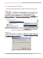
Click “Start” Æ “Settings” Æ “Control Panel” and then double click on
the “System” icon. Once the “System Properties” screen displayed, click
on ” Hardware” tab and then click on the “Device Manager” button.
Double-click on Ports (COM & LPT) item. If the device driver was
correctly installed, users can find the “ICPDAS I-7565-H1 USB2CAN” or
“ICPDAS I-7565-H2 USB2CAN” device listing and the “Virtual COM Port”
number that Windows has assigned to the device is COM3 like Figure 3-6.
Figure 3-6: Virtual COM Port Number
I-7565-H1/H2 High Speed USB/CAN Converter User’s Manual (Ver 1.1, Nov/2009) ------------- 20
3.3 Uninstall I-7565-H1/H2 Driver
Please follow the below steps to uninstall I-7565-H1/H2 device driver.
[ Step - 1 ]
Click “Start” Æ “Settings” Æ “Control Panel” and then double click on
the “System” icon. Once the “System Properties” screen displayed, click
on ” Hardware” tab and then click on the “Device Manager” button.
Double-click on Ports (COM & LPT) item. Please find the “ICPDAS I7565-H1 USB2CAN” or “ICPDAS I-7565-H2 USB2CAN” device listing and
right click mouse button on it and choose “Uninstall” item like Figure 3-7.
Figure 3-7: Uninstall I-7565-H1/H2 Driver (1)
[ Step - 2 ]
Click “OK” button to complete I-7565-H1/H2 device driver uninstallation like Figure 3-8. After that, the “ICPDAS I-7565-H1 USB2CAN”
or “ICPDAS I-7565-H2 USB2CAN” device listing will disappear on Ports
(COM & LPT) item.
Figure 3-8: Uninstall I-7565-H1/H2 Driver (2)
I-7565-H1/H2 High Speed USB/CAN Converter User’s Manual (Ver 1.1, Nov/2009) ------------- 21
4. Software Utility
I-7565-H1/H2 Utility is provided by ICP DAS to transmit / receive CAN
messages for CAN bus communication testing easily and quickly. In the
meanwhile, it can also display the time-stamp of each received CAN
message for data analyzing conveniently. I-7565-H1/H2 Utility can be
downloaded from the ICP DAS web site :
http://ftp.icpdas.com/pub/cd/fieldbus_cd/can/converter/i-7565h1h2/software/utility. The following is the main functions provided by I7565-H1/H2 Utility :
4.1
INI File Function
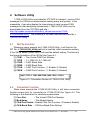
Whenever users execute the I-7565-H1/H2 Utility, it will look for the
INT file : I-7565-H1H2_Utility.ini first to load the initial connection setting.
If the INI file doesn’t exist, then it will load the default setting. The below is
the format illustration of the INI file like Figure 4-1.
[1] COM : The Virtual COM Port Number.
[2] TYPE : 1: I-7565-H1; 2: I-7565-H2.
[3] C1BR : CAN1 Baud Rate
[4] C2BR : CAN2 Baud Rate
[5] C1EN : CAN1 Port Function. (1: Enable; 0: Disable)
[6] C2EN : CAN2 Port Function. (1: Enable; 0: Disable)
Figure 4-1: Connection Screen of I-7565-H1/H2 Utility
4.2
Connection Function
When users execute the I-7565-H1/H2 Utility, it will show connection
function screen first for connecting to I-7565-H1/H2 like Figure 4-2. The
following is the illustration for connection parameters.
[1] Com Port
: The Virtual COM Port Number.
[2] Mod Name
: The Module Name.
[3] CAN Port Enable : Enable CAN Port Function. (Checked: Enable)
[4] CAN Baud Rate : CAN bus Baud Rate Setting.
I-7565-H1/H2 High Speed USB/CAN Converter User’s Manual (Ver 1.1, Nov/2009) ------------- 22
Figure 4-2: Connection Screen of I-7565-H1/H2 Utility
After finish the connection setting, please click “Connect” button to
connect to I-7565-H1/H2 module. Note that I-7565-H1/H2 doesn’t affect
the CAN bus communication when power on because the CAN port
function will keep disabled until users connect to I-7565-H1/H2
successfully. As soon as users disconnect to I-7565-H1/H2, the CAN port
function on I-7565-H1/H2 will be disabled again. Besides, users can also
click “Connect” item in the menu bar and choose “Connect To I-7565H1/H2” function to connect to I-7565-H1/H2 like Figure 4-3 or “Disconnect”
function to disconnect to I-7565-H1/H2 like Figure 4-4.
Figure 4-3: “Connect To I-7565-H1/H2” function
Figure 4-4: “Disconnect” function
I-7565-H1/H2 High Speed USB/CAN Converter User’s Manual (Ver 1.1, Nov/2009) ------------- 23
4.3
Communication Function
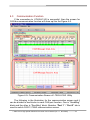
If the connection to I-7565-H1/H2 is successful, then the screen for
CAN bus communication function will show up like the Figure 4-5.
Figure 4-5: Communication Screen of I-7565-H1/H2 Utility
The following is the illustration for the communication screen and it
can be divided to two blocks in each CAN port function. One is “SendMsg”
block and the other is “RecvMsg” block. Besides, “Port 1” / “Port 2” tab is
used to switch CAN1 / CAN2 communication screen.
I-7565-H1/H2 High Speed USB/CAN Converter User’s Manual (Ver 1.1, Nov/2009) ------------- 24
[1] For “CAN1/2 SendMsg” block :
<1> “SendMsg Configuration” frame :
It is used to edit the CAN message parameters and users can
use “Add” button to add the CAN message to “CAN Message
Send Area”.
<2> “Add” button :
It will add the CAN message from “SendMsg Configuration”
area to the last row in “CAN Message Send Area”.
<3> “Modify” button :
It will modify the CAN message parameter from “SendMsg
Configuration” area to the assigned green row in “CAN
Message Send Area”.
<4> “Delete” button :
It will delete the CAN message of the assigned green row in
“CAN Message Send Area”.
<5> “Send” button :
It will send the CAN message of the assigned green row in
“CAN Message Send Area”. If the value in the “Timer” field is
zero, it will just send once. If not, it will send continuously by
PC timer.
<6> “HWSend” button :
It will send the CAN message of the assigned green row in
“CAN Message Send Area”. If the value in the “Timer” field is
zero, it will just send once. If not, it will send continuously by
module hardware timer and it will be more precise than PC
timer. If users want to send the CAN message with fixed
number, then before clicking “HWSend” button, please check
the “HWSendCnt” checkbox first like Figure 4-6.
I-7565-H1/H2 High Speed USB/CAN Converter User’s Manual (Ver 1.1, Nov/2009) ------------- 25
Figure 4-6: Send CAN Message by Hardware Timer
<7> “Clear” button :
It will clear the “SendCnt” value to be zero in “CAN Message
Send Area”.
<8> “SendCnt” field :
Whenever the CAN message is sent out once, the “SendCnt”
value will be added by 1 except “HWSend” function.
[2] For “CAN1/2 RecvMsg” block :
<1> “Display Type” option :
It is used to show the received CAN message data with
“Decimal “or “Hex” format in “CAN Message Receive Area”.
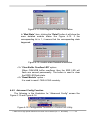
<2> “Start Record / Stop Record” button :
When clicking “Start Record” button, the received CAN
messages will be recorded in a file as ASCII text replacing
showing in “CAN Message Send Area”. When clicking “Stop
Record” button, it will stop recording the received CAN
messages on a file.
The filename format will be “CAN1_YYMMDD_HHMMSS.txt”
or “CAN2_YYMMDD_HHMMSS.txt”.
<3> “Rx Pause / Rx Start” button :
When clicking “Rx Pause” button, it will stop receiving the
CAN messages. When clicking “Rx Start” button, it will start to
receive the CAN messages.
<4> “Clear” button :
It will clear all the CAN message data in “CAN Message
Receive Area“ and the “RecvCnt” value to be zero.
<5> “Scrolling” checkbox :
If the “Scrolling” checkbox is checked, the received CAN
message data in “CAN Message Receive Area“ will be
updated and the “RecvCnt” value to be the newest
automatically. If not, it will not update the received CAN
message data in “CAN Message Receive Area“.
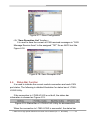
4.4
Config Function
In I-7565-H1/H2 Utility, it provides two kinds of configuration functions.
I-7565-H1/H2 High Speed USB/CAN Converter User’s Manual (Ver 1.1, Nov/2009) ------------- 26
One is “Module Config” and the other is “Advanced Config”. Users can
click “Configuration” item in the menu bar and choose one of them to show
the corresponding function screen like Figure 4-7.
Figure 4-7: Configuration Function of I-7565-H1/H2 Utility
4.4.1 Module Config Function
The following is the illustration for “Module Config” screen. It can be
divided to two blocks. One is “CAN Filter Setting” block and the other is
“Config / Info Option” block like Figure 4-8.
I-7565-H1/H2 High Speed USB/CAN Converter User’s Manual (Ver 1.1, Nov/2009) ------------- 27
Figure 4-8: Module Config Screen of I-7565-H1/H2 Utility
[1] For “CAN Filter Setting” block :
If users don’t set the CAN Filter function, then all CAN messages
will be able to be received in default. In “CAN Filter Setting” block,
users can set which CAN ID able to be received by I-7565-H1/H2
module.
<1> “Single ID” frame :
By clicking “Add” button to add the assigned single CAN ID to
“CAN Filter-ID Table” to set these assigned single CAN ID
able to be received.
<2> “Group ID” frame :
By clicking “Add” button to add the assigned group CAN ID to
“CAN Filter-ID Table” to set these assigned group CAN ID able
to be received.
<3> “CAN Controller” combobox :
It is used to choose which CAN port that users want to
configure currently.
<4> “Get CAN Accepted IDs” button :
It is used to get CAN Filter-ID data of the assigned CAN port
and showed in the “CAN Filter-ID Table”. The command result
also returns in the “Response” frame of “Config / Info Option”
block.
<5> “Set CAN Accepted IDs” button :
It is used to set CAN Filter-ID data of the assigned CAN port
according to the “CAN Filter-ID Table” content. The command
result also returns in the “Response” frame of “Config / Info
Option” block.
<6> “Save File” button :
It is used to save the “CAN Filter-ID Table” content to file.
<7> “Load File” button :
It is used to load the CAN Filter-ID data from file to “CAN
Filter-ID Table”.
<8> “Delete Row” button :
It is used to delete the CAN Filter-ID data of the assigned
green row in “CAN Filter-ID Table”.
<9> “Clear Table” button :
It is used to clear all the contents in “CAN Filter-ID Table”.
I-7565-H1/H2 High Speed USB/CAN Converter User’s Manual (Ver 1.1, Nov/2009) ------------- 28
[2] For “Config / Info Option” block :
There are several option functions provided for I-7565-H1/H2. The
following will illustrate all these functions.
<1> “Get_ModInfo” option :
It is used to get the related module info including “Module
Name” and “Firmware Version” like Figure 4-9.
Figure 4-9: Module Info
<2> “Get_CANStatus” option :
It is used to get the assigned CAN port status like Figure 4-10.
Figure 4-10: CAN Status
In “Register” item, clicking the “Detail” button it will show the
more detailed CAN port register status like Figure 4-11. If the
corresponding bit is 1, it means that the corresponding state
happened.
I-7565-H1/H2 High Speed USB/CAN Converter User’s Manual (Ver 1.1, Nov/2009) ------------- 29
Figure 4-11: CAN Register Detailed Information
In “Mod State” item, clicking the “Detail” button it will show the
more detailed module status like Figure 4-12. If the
corresponding bit is 1, it means that the corresponding state
happened.
Figure 4-12: module state Detailed Information
<3> “Clear Buffer Overflow LED” option :
When CAN/USB buffer overflows, then the ERR LED will
flash one second permanently. The button is used to clear
the ERR LED flash state.
<4> “Reset Module” option :
It is used to reset I-7565-H1/H2 remotely.
4.4.2 Advanced Config Function
The following is the illustration for “Advanced Config” screen like
Figure 4-13 and Figure 4-14.
Figure 4-13: Configuration Function of I-7565-H1/H2 Utility
I-7565-H1/H2 High Speed USB/CAN Converter User’s Manual (Ver 1.1, Nov/2009) ------------- 30
Figure 4-14: Advanced Config of I-7565-H1/H2
<1> “Get CAN2USB Current Flow” option :
It is used to get the current CAN message flow (unit: fps) in
the CAN port of I-7565-H1/H2.
<2> “Get CAN2USB Hardware Speed” option :
It is used to get the current setting value for CAN to USB
hardware transmission speed of I-7565-H1/H2.
<3> “Set CAN2USB Hardware Speed” option :
It is used to set CAN to USB hardware transmission speed of
I-7565-H1/H2 module. Users can set the speed from 1000 fps
~ 3000 fps. The setting rule is that users can use “Get
CAN2USB Current Flow” function first to know the current
CAN message flow and then choose a setting value that is
larger a little than that. Apply the rule and it will reduce the
CAN message loss condition especially when the
performance on users’ PC is not good.
4.5
Data Log Function
By clicking “File” item in the menu bar to execute the related data log
function. The following is the illustration like Figure 4-15.
I-7565-H1/H2 High Speed USB/CAN Converter User’s Manual (Ver 1.1, Nov/2009) ------------- 31
Figure 4-15: Advanced Config of I-7565-H1/H2
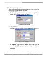
<1> “Load Configuration” function :
It is used to load the previous “CAN Send Message Configuration”
to “CAN Message Send Area” from the assigned “TXT” file like Figure
4-16.
Figure 4-16: Load Configuration
<2> “Save Configuration” function :
It is used to save the current “CAN Send Message Configuration”
in the “CAN Message Send Area” to the assigned “TXT” file like Figure
4-17.
I-7565-H1/H2 High Speed USB/CAN Converter User’s Manual (Ver 1.1, Nov/2009) ------------- 32
Figure 4-17: Save Configuration
<3> “Save Reception List” function :
It is used to save the current all CAN received messages in “CAN
Message Receive Area” to the assigned “TXT” file as ASCII text like
Figure 4-18.
Figure 4-18: Save Reception List
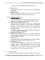
4.6
Status Bar Function
It is used to indicate the current module connection and each CAN
port status. The following is detailed illustration for status bar of I-7565H1/H2 Utility.
If the connection to I-7565-H1/H2 is not built, the status bar
information is showed as Figure 4-19.
Figure 4-19: Status Bar of I-7565-H1/H2 Utility for disconnection
When the connection to I-7565-H1/H2 is successful, the status bar
I-7565-H1/H2 High Speed USB/CAN Converter User’s Manual (Ver 1.1, Nov/2009) ------------- 33
information is showed as Figure 4-20 and it can be divided for four blocks.
(1) Module Name => Indicate the connected module name and the
virtual com port which is in use.
(2) Port Status
=> Indicate the CAN port enabled or not.
(3) Baud Rate
=> Indicate the CAN port baud rate.
(4) Company
=> ICP DAS Co., LTD
Figure 4-20: Status Bar of I-7565-H1/H2 Utility for disconnection
I-7565-H1/H2 High Speed USB/CAN Converter User’s Manual (Ver 1.1, Nov/2009) ------------- 34
5. API Library -- VCI_CAN.dll
Users can develop own CAN bus program by I-7565-H1/H2 API
library, VCI_CAN.dll, quickly and easily. The VCI_CAN library and demos
can be downloaded from the ICP DAS web site :
http://ftp.icpdas.com/pub/cd/fieldbus_cd/can/converter/i-7565h1h2/software/library.
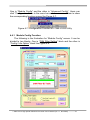
5.1 API Library Overview
All the functions provided by VCI_CAN library can be separated into
five groups shown in Figure 5-1.
Figure 5-1: Five Function Groups of VCI_CAN Library
[ Init Function ]
These functions are used to enable / disable CAN port function of
I-7565-H1/H2.
[ Module Config Function ]
These functions are used to set / get the parameters or information of
I-7565-H1/H2.
I-7565-H1/H2 High Speed USB/CAN Converter User’s Manual (Ver 1.1, Nov/2009) ------------- 35
[ Communication Function ]
These functions are used to send / receive CAN message through
I-7565-H1/H2.
[ Software Buffer Function ]
When “VCI_OpenCAN” function is successful, the received CAN
messages will be saved in software buffer provided by VCI_CAN library
first and users need to use “VCI_RecvCANMsg” function to get them.
The software buffer size is 65536 for each CAN port. These related
functions are used to operate the software buffer of VCI_CAN library.
[ Other Function ]
These functions are used to get the VCI_CAN library information or
helpful for users’ program.
5.2 API Library Function Table
All the functions provided in the VCI_CAN.dll are listed in the
following table.
Table 5-1: “Init” Function Table
No.
Function Name
Description
1
VCI_OpenCAN
Enable CAN port function of I-7565-H1/H2
2
VCI_CloseCAN
Disable CAN port function of I-7565-H1/H2
Table 5-2: “Module Config” Function Table
No.
Function Name
Description
1
VCI_Set_CANFID
Set CAN Filter-ID in the assigned CAN port
2
VCI_Get_CANFID
Get CAN Filter-ID in the assigned CAN port
3
VCI_Get_CANStatus
Get the assigned CAN port status
4
VCI_Clr_BufOverflowLED
Clear buffer overflow ERR LED state in the
assigned CAN port
5
VCI_Get_MODInfo
Get the module information
6
VCI_Rst_MOD
Reset module
I-7565-H1/H2 High Speed USB/CAN Converter User’s Manual (Ver 1.1, Nov/2009) ------------- 36
Table 5-3: “Communication” Function Table
No.
Function Name
Description
1
VCI_SendCANMsg
Send CAN message in the assigned CAN
port
2
VCI_RecvCANMsg
Receive CAN message in the assigned CAN
port
3
VCI_EnableHWCyclicTxMsg
Send CAN message in the assigned CAN
port by using module hardware timer
4
VCI_DisableHWCyclicTxMsg
Stop sending CAN message by module
hardware timer
Table 5-4: “Software Buffer” Function Table
No.
Function Name
Description
1
VCI_Get_RxMsgCnt
Get the count of the received CAN messages
saved in software buffer that are not received
by users’ program in the assigned CAN port
2
VCI_Get_RxMsgBufIsFull
Get the software buffer state whether it is full
or not in the assigned CAN port
3
VCI_Clr_RxMsgBuf
Clear the software buffer in the assigned CAN
port
Table 5-5: “Other” Function Table
No.
Function Name
Description
1
VCI_Get_DllVer
Get the version of VCI_CAN library.
2
VCI_DoEvents
Release CPU resource temporarily
I-7565-H1/H2 High Speed USB/CAN Converter User’s Manual (Ver 1.1, Nov/2009) ------------- 37
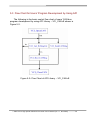
5.3 Flow Chart for Users’ Program Development by Using API
The following is the basic control flow chart of users’ CAN bus
program development by using API Library – VCI_CAN.dll shown in
Figure 5-2.
Figure 5-2: Flow Chart of API Library – VCI_CAN.dll
I-7565-H1/H2 High Speed USB/CAN Converter User’s Manual (Ver 1.1, Nov/2009) ------------- 38
5.4 Init Function
These functions are used to enable / disable CAN port function of I7565-H1/H2.
5.4.1 VCI_OpenCAN
This function is used to enable the assigned CAN port function of I7565-H1/H2. After the CAN port function is enabled, users can use
“Communication” functions to send / receive CAN messages.
Syntax :
int VCI_OpenCAN (
PVCI_CAN_PARAM pCANPARAM
);
Parameter :
pCANPARAM:
[in] A structure pointer of _VCI_CAN_PARAM is used to set the CAN
port communication parameters shown as below.
typedef struct _VCI_CAN_PARAM{
BYTE DevPort;
BYTE DevType;
DWORD CAN1_Baud;
DWORD CAN2_Baud;
} _VCI_CAN_PARAM, *PVCI_CAN_PARAM;
DevPort
DevType
CAN1_Baud
CAN2_Baud
: The virtual com port number
: The module type (1: I-7565-H1; 2: I-7565-H2)
: CAN1 port baud rate
(0
: Disable CAN1 port
Others: Enable CAN1 port)
: CAN2 port baud rate
(0
: Disable CAN2 port
Others: Enable CAN2 port)
Return Values :
Return 0 means success, others means failure.
Examples :
Int Ret;
_VCI_CAN_PARAM pCANPARAM;
pCANPARAM.DevPort = 1;
// Virtual com port = 1
I-7565-H1/H2 High Speed USB/CAN Converter User’s Manual (Ver 1.1, Nov/2009) ------------- 39
pCANPARAM.DevType = 1;
pCANPARAM.CAN1_Baud = 250000;
pCANPARAM.CAN2_Baud = 1000000;
Ret = VCI_OpenCAN(&pCANPARAM);
// I-7565-H1
// 250 Kbps
// 1000K bps
// Enable CAN port
I-7565-H1/H2 High Speed USB/CAN Converter User’s Manual (Ver 1.1, Nov/2009) ------------- 40
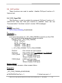
5.4.2 VCI_CloseCAN
This function is used to disable all CAN port function of
I-7565-H1/H2. After the CAN port function is disabled, it will not interfere
the communication of CAN bus network even if I-7565-H1/H2 is power on.
Syntax :
int VCI_CloseCAN (
BYTE DevPort
);
Parameter :
DevPort:
[in] The virtual com port number
Return Values :
Return 0 means success, others means failure.
Examples :
Int Ret;
BYTE ComPort;
ComPort = 1;
Ret = VCI_CloseCAN(ComPort);
// Disable CAN port
I-7565-H1/H2 High Speed USB/CAN Converter User’s Manual (Ver 1.1, Nov/2009) ------------- 41
5.5 Module Config Function
These functions are used to set / get the parameters or information of
I-7565-H1/H2.
5.5.1 VCI_Set_CANFID
This function is used to set CAN Filter-ID in the assigned CAN port.
Syntax :
int VCI_Set_CANFID (
BYTE CAN_No,
PVCI_CAN_FID pCANFID
);
Parameter :
CAN_No:
[in] The assigned CAN port number.
pCANFID:
[in] A structure pointer of _VCI_CAN_FilterID is used to set the CAN
Filter-ID data shown as below.
typedef struct _VCI_CAN_FilterID{
WORD SSFF_Num;
WORD GSFF_Num;
WORD SEFF_Num;
WORD GEFF_Num;
WORD SSFF_FID[512];
DWORD GSFF_FID[512];
DWORD SEFF_FID[512];
DWORD GEFF_FID[512];
} _VCI_CAN_FilterID, *PVCI_CAN_FID;
SSFF_Num
GSFF_Num
SEFF_Num
GEFF_Num
SSFF_FID[512]
GSFF_FID[512]
SEFF_FID[512]
GEFF_FID[512]
: Single 11-bit CAN Filter-ID number
: Group 11-bit CAN Filter-ID number
: Single 29-bit CAN Filter-ID number
: Group 29-bit CAN Filter-ID number
: Single 11-bit CAN Filter-ID data array
: Group 11-bit CAN Filter-ID data array
: Single 29-bit CAN Filter-ID data array
: Group 29-bit CAN Filter-ID data array
I-7565-H1/H2 High Speed USB/CAN Converter User’s Manual (Ver 1.1, Nov/2009) ------------- 42
Return Values :
Return 0 means success, others means failure.
Examples :
Int Ret;
BYTE CAN_No;
_VCI_CAN_FilterID pCANFID1;
//Single 11-bit Fitler-ID
WORD SSFID[3]={0x0003, 0x0002, 0x0001};
//Group 11-bit Fitler-ID
DWORD GSFID[2]={0x00300040, 0x00100020};
//Single 29-bit Fitler-ID
DWORD SEFID[3]={0x00000013, 0x00000012, 0x00000011};
//Group 29-bit Fitler-ID
DWORD GEFID[4]={0x00000300, 0x00000400, 0x00000100, x00000200};
CAN_No=1;
pCANFID1.SSFF_Num = sizeof(SSFID)/sizeof(WORD);
pCANFID1.GSFF_Num = sizeof(GSFID)/sizeof(DWORD);
pCANFID1.SEFF_Num = sizeof(SEFID)/sizeof(DWORD);
pCANFID1.GEFF_Num = sizeof(GEFID)/sizeof(DWORD);
memcpy(pCANFID1.SSFF_FID, SSFID, pCANFID1.SSFF_Num*2);
memcpy(pCANFID1.GSFF_FID, GSFID, pCANFID1.GSFF_Num*4);
memcpy(pCANFID1.SEFF_FID, SEFID, pCANFID1.SEFF_Num*4);
memcpy(pCANFID1.GEFF_FID, GEFID, pCANFID1.GEFF_Num*4);
Ret = VCI_Set_CANFID(CAN_No, &pCANFID1);
// Set CAN Filter-ID
I-7565-H1/H2 High Speed USB/CAN Converter User’s Manual (Ver 1.1, Nov/2009) ------------- 43
5.5.2 VCI_Get_CANFID
This function is used to get CAN Filter-ID in the assigned CAN port.
Syntax :
int VCI_Get_CANFID (
BYTE CAN_No,
PVCI_CAN_FID pCANFID
);
Parameter :
CAN_No:
[in] The assigned CAN port number.
pCANFID:
[out] A structure pointer of _VCI_CAN_FilterID is used to receive the
CAN Filter-ID data shown as below.
typedef struct _VCI_CAN_FilterID{
WORD SSFF_Num;
WORD GSFF_Num;
WORD SEFF_Num;
WORD GEFF_Num;
WORD SSFF_FID[512];
DWORD GSFF_FID[512];
DWORD SEFF_FID[512];
DWORD GEFF_FID[512];
} _VCI_CAN_FilterID, *PVCI_CAN_FID;
SSFF_Num
GSFF_Num
SEFF_Num
GEFF_Num
SSFF_FID[512]
GSFF_FID[512]
SEFF_FID[512]
GEFF_FID[512]
: Single 11-bit CAN Filter-ID number
: Group 11-bit CAN Filter-ID number
: Single 29-bit CAN Filter-ID number
: Group 29-bit CAN Filter-ID number
: Single 11-bit CAN Filter-ID data array
: Group 11-bit CAN Filter-ID data array
: Single 29-bit CAN Filter-ID data array
: Group 29-bit CAN Filter-ID data array
Return Values :
Return 0 means success, others means failure.
I-7565-H1/H2 High Speed USB/CAN Converter User’s Manual (Ver 1.1, Nov/2009) ------------- 44
Examples :
Int Ret;
BYTE CAN_No;
_VCI_CAN_FilterID pCANFID;
WORD SID11_EndNum=0, GID11_EndNum=0;
WORD SID29_EndNum=0, GID29_EndNum=0;
CAN_No=1;
Ret = VCI_Get_CANFID(CAN_No, &pCANFID);
SID11_EndNum = CANFID.SSFF_Num;
GID11_EndNum = CANFID.GSFF_Num;
SID29_EndNum = CANFID.SEFF_Num;
GID29_EndNum = CANFID.GEFF_Num;
// Get CAN Filter-ID
I-7565-H1/H2 High Speed USB/CAN Converter User’s Manual (Ver 1.1, Nov/2009) ------------- 45
5.5.3 VCI_Get_CANStatus
This function is used to get the assigned CAN port status.
Syntax :
int VCI_Get_CANStatus (
BYTE CAN_No,
PVCI_CAN_STATUS pCANStatus
);
Parameter :
CAN_No:
[in] The assigned CAN port number.
pCANStatus:
[out] A structure pointer of _VCI_CAN_STATUS is used to receive the
CAN port status shown as below.
typedef struct _VCI_CAN_STATUS{
DWORD CurCANBaud;
BYTE CANReg;
BYTE CANTxErrCnt;
BYTE CANRxErrCnt;
BYTE MODState;
DWORD Reserved;
} _VCI_CAN_STATUS, *PVCI_CAN_STATUS;
CurCANBaud
CANReg
CANTxErrCnt
CANRxErrCnt
MODState
: Return the assigned CAN port baud rate
: Return the assigned CAN port register value
: Return the assigned CAN port Tx error count
: Return the assigned CAN port Rx error count
: Return the module state
Return Values :
Return 0 means success, others means failure.
Examples :
Int Ret;
BYTE CAN_No, Module_State;
_VCI_CAN_STATUS CANSTA;
CAN_No=1;
Ret = VCI_Get_CANStatus(CAN_No, &CANSTA); // Get CAN port status
Module_State = CANSTA.MODState;
I-7565-H1/H2 High Speed USB/CAN Converter User’s Manual (Ver 1.1, Nov/2009) ------------- 46
5.5.4 VCI_Clr_BufOverflowLED
This function is used to clear buffer overflow ERR LED state (flash per
second) in the assigned CAN port.
Syntax :
int VCI_Clr_BufOverflowLED (
BYTE CAN_No,
);
Parameter :
CAN_No:
[in] The assigned CAN port number.
Return Values :
Return 0 means success, others means failure.
Examples :
Int Ret;
BYTE CAN_No;
CAN_No=1;
Ret = VCI_Clr_BufOverflowLED(CAN_No); // Clear Buffer Overflow LED
I-7565-H1/H2 High Speed USB/CAN Converter User’s Manual (Ver 1.1, Nov/2009) ------------- 47
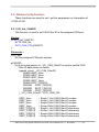
5.5.5 VCI_Get_MODInfo
This function is used to get module information.
Syntax :
int VCI_Get_MODInfo (
PVCI_MOD_INFO pMODInfo
);
Parameter :
pMODInfo:
[out] A structure pointer of _VCI_MODULE_INFO is used to receive
the module information shown as below.
typedef struct _VCI_MODULE_INFO{
char Mod_ID[12];
char FW_Ver[12];
} _VCI_MODULE_INFO, *PVCI_MOD_INFO;
Mod_ID[12]
FW_Ver[12]
: Return the module name string
: Return the module firmware version string
Return Values :
Return 0 means success, others means failure.
Examples :
Int Ret;
char Module_ID[12], Firmware_Ver[12];
_VCI_MODULE_INFO CAN_ModInfo;
Ret = VCI_Get_MODInfo(&CAN_ModInfo);
// Get module information
sprintf(Module_ID, “%s”, CAN_ModInfo.Mod_ID);
sprintf(Firmware_Ver, “%s”, CAN_ModInfo.FW_Ver);
I-7565-H1/H2 High Speed USB/CAN Converter User’s Manual (Ver 1.1, Nov/2009) ------------- 48
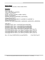
5.5.6 VCI_Rst_MOD
This function is used to reset module.
Syntax :
int VCI_Rst_MOD (
void
);
Parameter :
None
Return Values :
Return 0 means success, others means failure.
Examples :
Int Ret;
Ret = VCI_Rst_MOD(); // Reset Module
I-7565-H1/H2 High Speed USB/CAN Converter User’s Manual (Ver 1.1, Nov/2009) ------------- 49
5.6 Communication Function
These functions are used to send / receive CAN messages.
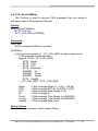
5.6.1 VCI_SendCANMsg
This function is used to send CAN messages in the assigned CAN
port.
Syntax :
int VCI_SendCANMsg (
BYTE CAN_No,
PVCI_CAN_MSG pCANMsg
);
Parameter :
CAN_No:
[in] The assigned CAN port number.
pCANMsg:
[in] A structure pointer of _VCI_CAN_MSG is used to set the CAN
message parameters shown as below.
typedef struct _VCI_CAN_MSG{
BYTE Mode;
BYTE RTR;
BYTE DLC;
BYTE Reserved;
DWORD ID;
DWORD TimeL;
DWORD TimeH;
BYTE Data[8];
} _VCI_CAN_MSG, *PVCI_CAN_MSG;
Mode
RTR
DLC
ID
TimeL
TimeH
Data[8]
: CAN message Mode (0: 11-bit; 1: 29-bit)
: CAN message RTR (0: No RTR; 1: RTR)
: CAN message Data Length (0~8)
: CAN message ID
: CAN message Time-Stamp (Lo-DWORD)
: CAN message Time-Stamp (Hi-DWORD)
: CAN message Data Array
Return Values :
I-7565-H1/H2 High Speed USB/CAN Converter User’s Manual (Ver 1.1, Nov/2009) ------------- 50
Return 0 means success, others means failure.
Examples :
Int Ret;
BYTE CAN_No;
_VCI_CAN_MSG CAN_SendMsg;
CAN_No=1;
CAN_SendMsg.Mode = 1;
CAN_SendMsg.RTR = 0;
CAN_SendMsg.ID
= 0x1;
CAN_SendMsg.DLC = 8;
CAN_SendMsg.Data[0]= 0x12;
CAN_SendMsg.Data[1]= 0x34;
CAN_SendMsg.Data[2]= 0x56;
CAN_SendMsg.Data[3]= 0x78;
CAN_SendMsg.Data[4]= 0x90;
CAN_SendMsg.Data[5]= 0xAB;
CAN_SendMsg.Data[6]= 0xCD;
CAN_SendMsg.Data[7]= 0xEF;
Ret = VCI_SendCANMsg(CAN_No, &CAN_SendMsg); // Send CAN Msg
I-7565-H1/H2 High Speed USB/CAN Converter User’s Manual (Ver 1.1, Nov/2009) ------------- 51
5.6.2 VCI_RecvCANMsg
This function is used to receive CAN messages that are saved in
software buffer in the assigned CAN port.
Syntax :
int VCI_RecvCANMsg (
BYTE CAN_No,
PVCI_CAN_MSG pCANMsg
);
Parameter :
CAN_No:
[in] The assigned CAN port number.
pCANMsg:
[out] A structure pointer of _VCI_CAN_MSG is used to receive the
CAN message shown as below.
typedef struct _VCI_CAN_MSG{
BYTE Mode;
BYTE RTR;
BYTE DLC;
BYTE Reserved;
DWORD ID;
DWORD TimeL;
DWORD TimeH;
BYTE Data[8];
} _VCI_CAN_MSG, *PVCI_CAN_MSG;
Mode
RTR
DLC
ID
TimeL
TimeH
Data[8]
: CAN message Mode (0: 11-bit; 1: 29-bit)
: CAN message RTR (0: No RTR; 1: RTR)
: CAN message Data Length (0~8)
: CAN message ID
: CAN message Time-Stamp (Lo-DWORD)
: CAN message Time-Stamp (Hi-DWORD)
: CAN message Data Array
Return Values :
Return 0 means success, others means failure.
I-7565-H1/H2 High Speed USB/CAN Converter User’s Manual (Ver 1.1, Nov/2009) ------------- 52
Examples :
Int Ret, i;
BYTE CAN_No;
BYTE CANMsg_Mode, CANMsg_RTR, CANMsg_DLC, CANMsg_Data[8];
DWORD CANMsg_ID, CANMsg;
Double CANMsg_Time;
_VCI_CAN_MSG CAN_RecvMsg;
CAN_No=1;
Ret = VCI_RecvCANMsg(CAN_No, &CAN_RecvMsg); // Recv CAN Msg
CANMsg_Mode = CAN_RecvMsg.Mode;
CANMsg_RTR = CAN_RecvMsg.RTR;
CANMsg_ID = CAN_RecvMsg.ID;
CANMsg_DLC = CAN_RecvMsg.DLC;
CANMsg_Time =
(double)(CAN_RecvMsg.TimeH*pow(2.0,32.0))+(double)((double)CAN_R
ecvMsg.TimeL/10000));
For(i=0; i< CANMsg_DLC; i++){
CANMsg_Data[i] = CAN_RecvMsg.Data[i]
}
I-7565-H1/H2 High Speed USB/CAN Converter User’s Manual (Ver 1.1, Nov/2009) ------------- 53
5.6.3 VCI_EnableHWCyclicTxMsg
This function is used to send CAN messages in the assigned CAN
port by using module hardware timer and it will be more precise than PC
software timer.
Syntax :
int VCI_EnableHWCyclicTxMsg (
BYTE CAN_No,
PVCI_CAN_MSG pCANMsg,
DWORD TimePeriod,
DWORD TransmitTimes
);
Parameter :
CAN_No:
[in] The assigned CAN port number.
pCANMsg:
[in] A structure pointer of _VCI_CAN_MSG is used to set the CAN
message parameters shown as below.
typedef struct _VCI_CAN_MSG{
BYTE Mode;
BYTE RTR;
BYTE DLC;
BYTE Reserved;
DWORD ID;
DWORD TimeL;
DWORD TimeH;
BYTE Data[8];
} _VCI_CAN_MSG, *PVCI_CAN_MSG;
Mode
RTR
DLC
ID
TimeL
TimeH
Data[8]
: CAN message Mode (0: 11-bit; 1: 29-bit)
: CAN message RTR (0: No RTR; 1: RTR)
: CAN message Data Length (0~8)
: CAN message ID
: CAN message Time-Stamp (Lo-DWORD)
: CAN message Time-Stamp (Hi-DWORD)
: CAN message Data Array
I-7565-H1/H2 High Speed USB/CAN Converter User’s Manual (Ver 1.1, Nov/2009) ------------- 54
TimePeriod:
[in] The time period of module hardware timer for sending CAN
message. If the value is zero, this function doesn’t work.
TransmitTimes:
[in] The count for sending CAN message. If the value is zero, it means
that CAN message will be sent periodically and permanently.
Return Values :
Return 0 means success, others means failure.
Examples :
Int Ret;
BYTE CAN_No;
_VCI_CAN_MSG CAN_SendMsg;
CAN_No=1;
CAN_SendMsg.Mode = 1;
CAN_SendMsg.RTR = 0;
CAN_SendMsg.ID
= 0x1;
CAN_SendMsg.DLC = 8;
CAN_SendMsg.Data[0]= 0x12;
CAN_SendMsg.Data[1]= 0x34;
CAN_SendMsg.Data[2]= 0x56;
CAN_SendMsg.Data[3]= 0x78;
CAN_SendMsg.Data[4]= 0x90;
CAN_SendMsg.Data[5]= 0xAB;
CAN_SendMsg.Data[6]= 0xCD;
CAN_SendMsg.Data[7]= 0xEF;
//Send 200 CANMsg with 10ms period and then stop
Ret = VCI_EnableHWCyclicTxMsg(CAN_No, &CAN_SendMsg, 10, 200);
//Send CANMsg with 10ms period permanently
//Ret = VCI_EnableHWCyclicTxMsg(CAN_No, &CAN_SendMsg, 10, 0);
I-7565-H1/H2 High Speed USB/CAN Converter User’s Manual (Ver 1.1, Nov/2009) ------------- 55
5.6.4 VCI_DisableHWCyclicTxMsg
This function is used to stop sending CAN messages by module
hardware timer.
Syntax :
int VCI_DisableHWCyclicTxMsg (
void
);
Parameter :
None
Return Values :
Return 0 means success, others means failure.
Examples :
Int Ret;
Ret = VCI_DisableHWCyclicTxMsg(); // Disable module hardware timer
I-7565-H1/H2 High Speed USB/CAN Converter User’s Manual (Ver 1.1, Nov/2009) ------------- 56
5.7 Software Buffer Function
When users’ program receives CAN messages, these received CAN
messages will be saved in software buffer provided by VCI_CAN library
first and users need to use “VCI_RecvCANMsg” function to get these
received CAN messages saved in software buffer. The software buffer
size is 65536 for each CAN port.
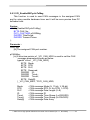
5.7.1 VCI_Get_RxMsgCnt
This function is used to get the count of these received CAN
messages saved in software buffer that are not received by users’
program in the assigned CAN port.
Syntax :
int VCI_Get_RxMsgCnt (
BYTE CAN_No,
DWORD* RxMsgCnt
);
Parameter :
CAN_No:
[in] The assigned CAN port number.
RxMsgCnt:
[out] The pointer is used to receive the CAN message count saved in
software buffer.
Return Values :
Return 0 means success, others means failure.
Examples :
Int Ret;
BYTE CAN_No;
DWORD RxMsgCnt;
CAN_No=1;
Ret = VCI_Get_RxMsgCnt(CAN_No, &RxMsgCnt); // Recv RxMsg count
I-7565-H1/H2 High Speed USB/CAN Converter User’s Manual (Ver 1.1, Nov/2009) ------------- 57
5.7.2 VCI_Get_RxMsgBufIsFull
This function is used to get the software buffer state whether it is full or
not in the assigned CAN port. If the software buffer is full, it means that
some CAN messages are lost.
Syntax :
int VCI_Get_RxMsgBufIsFull (
BYTE CAN_No,
BYTE* Flag
);
Parameter :
CAN_No:
[in] The assigned CAN port number.
Flag:
[out] The pointer is used to receive the state of software buffer. If the
value is zero, the software buffer is not full. If not, it means that
the software buffer is full.
Return Values :
Return 0 means success, others means failure.
Examples :
Int Ret;
BYTE CAN_No;
BYTE RxSoftBufFull_Flag;
CAN_No=1;
Ret = VCI_Get_RxMsgBufIsFull(CAN_No, &RxSoftBufFull_Flag);
I-7565-H1/H2 High Speed USB/CAN Converter User’s Manual (Ver 1.1, Nov/2009) ------------- 58
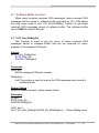
5.7.3 VCI_Clr_RxMsgBuf
This function is used to clear the software buffer in the assigned CAN
port.
Syntax :
int VCI_Clr_RxMsgBuf (
BYTE CAN_No,
);
Parameter :
CAN_No:
[in] The assigned CAN port number.
Return Values :
Return 0 means success, others means failure.
Examples :
Int Ret;
BYTE CAN_No;
CAN_No=1;
Ret = VCI_Clr_RxMsgBuf(CAN_No);
I-7565-H1/H2 High Speed USB/CAN Converter User’s Manual (Ver 1.1, Nov/2009) ------------- 59
5.8 Other Function
These functions are used to get the VCI_CAN library information or
helpful for users’ program.
5.8.1 VCI_Get_DllVer
This function is used to get the version of VCI_CAN library.
Syntax :
DWORD VCI_Get_DllVer (
void
);
Parameter :
None
Return Values :
Return the VCI_CAN library version. Hi-byte is the major version and
lo-byte is the minor version.
Examples :
DWORD DllVer;
char VCI_DllVer[10];
DllVer = VCI_Get_DllVer();
sprintf(VCI_DllVer, “v%lu.%02lu", (DllVer>>8)&0xFF, DllVer&0xFF);
I-7565-H1/H2 High Speed USB/CAN Converter User’s Manual (Ver 1.1, Nov/2009) ------------- 60
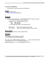
5.8.2 VCI_DoEvents
This function is used to release CPU resource temporarily.
Syntax :
void VCI_DoEvents (
void
);
Parameter :
None
Return Values :
None
Examples :
VCI_DoEvents() ;
I-7565-H1/H2 High Speed USB/CAN Converter User’s Manual (Ver 1.1, Nov/2009) ------------- 61
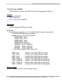
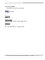
5.9 Return Code
The return value is used to show the result of executing VCI_CAN
library functions. The following is the all return codes.
#define No_Err
#define DEV_ModName_Err
#define DEV_ModNotExist_Err
0 //No Error
1 //The Module Name Error
2 //The Module doesn't exist in this
Port
#define DEV_PortNotExist_Err 3 //The Port doesn't Exist
#define DEV_PortInUse_Err
4 //The Port is in Used
#define DEV_PortNotOpen_Err 5 //The Port doesn't Open
#define CAN_ConfigFail_Err
6 //CAN Hardware Init Fail
#define CAN_HARDWARE_Err 7 //CAN Hardware Init Fail
#define CAN_PortNo_Err
8 //The Device doesn't support this
CAN Port
#define CAN_FIDLength_Err
9 //The CAN Filter-ID Number
exceed Max Number
#define CAN_DevDisconnect_Err10 //The Connection of device is
broken
#define CAN_TimeOut_Err
11 //The Config Command Timeout
#define CAN_ConfigCmd_Err
12 //The Config Command doesn't
support
#define CAN_ConfigBusy_Err
13 //The Config Command is busy
#define CAN_RxBufEmpty
14 //The CAN Receive Buffer is empty
#define CAN_TxBufFull
15 //The CAN Send Buffer is full
I-7565-H1/H2 High Speed USB/CAN Converter User’s Manual (Ver 1.1, Nov/2009) ------------- 62
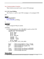
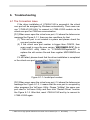
6. Troubleshooting
6.1 The Connection Issue
If the driver installation of I-7565-H1/H2 is successful, the virtual
com port will be assigned by Windows automatically. Then users can
use “I-7565-H1/H2 Utility” to connect to I-7565-H1/H2 module via the
virtual com port for CAN bus communication.
[Q1] When users open the virtual com port, if it shows the below error
message like Figure 6-1-1, there are two conditions for that.
(1) This com port is not existed in system and please check the
com port number again.
(2) If the virtual com port number is bigger than COM16, then
users need to copy the new version “MSCOMM32.OCX” file in
I-7565-H1H2 utility folder to “C:\WINDOWS\system32\” to
replace the old version file and then register MSCOMM32.ocx
again.
If it still failed, please check that the driver installation is completed
or the virtual com port is correct for I-7565-H1/H2.
Figure 6-1-1: Invalid port number
[Q2] When users open the virtual com port, if it shows the below error
message like Figure 6-1-2, it means that the com port is occupied by
other programs like VxComm Utility. Please “UnMap” the same com
port used in VxComm Utility and then click “Restart Driver” function
like Figure 6-1-3. After that, reset I-7565-H1/H2 and try to connect to
I-7565-H1/H2 again.
I-7565-H1/H2 High Speed USB/CAN Converter User’s Manual (Ver 1.1, Nov/2009) ------------- 63
Figure 6-1-2: The device is not open
Figure 6-1-3: Virtual COM of VxComm Utility
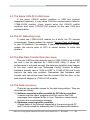
6.2The CAN Baud Rate Issue
(1) The CAN baud rate mismatch:
If the I-7565-H1/H2 CAN baud rate is not the same as the CAN
baud rate on the CAN bus network, the RUN LED on the I-7565H1/H2 will flash per 100ms because the I-7565-H1/H2 cannot send
any CAN message to the CAN bus network. Users can get the CAN
status of I-7565-H1/H2 by using “I-7565-H1/H2 Utility” to help users
understand what is going in the module.
(2) The user-defined CAN baud rate setting:
If users want to use the user-defined CAN baud rate, in the
“Connect to I-7565-H1/H2” screen of “I-7565-H1/H2 Utility”, users can
choose the “Defined” item and input the user-defined CAN baud rate
value (for example: 83.333) in the right field of the “Baud Rate” frame
like Figure 6-2. Then click “Connect” button to connect to I-7565H1/H2.
I-7565-H1/H2 High Speed USB/CAN Converter User’s Manual (Ver 1.1, Nov/2009) ------------- 64
Figure 6-2: User-defined CAN Baud Rate for I-7565-H1/H2
(3) The rule of user-defined CAN baud rate setting in the SJA1000
CAN devices for communication compatible with I-7565-H1/H2:
If users use I-7565-H1/H2 to communicate with SJA1000 CAN
devices and CAN baud rate is user-defined CAN baud rate. Then in
SJA1000 CAN devices, users need to choose a set of proper CAN
parameter (BTR0 & BTR1) for communication compatible with I7565-H1/H2 and the rule is as follows:
(1) The “Samples” value is 1.
(1) The “SJW” value is as small as possible. (1 is the best).
(2) The “Tseg2” value is as small as possible. (1 is the best)
(3) The “Tseg1” value is as large as possible.
According to the above four rules, users can choose the proper
BTR0 and BTR0. For example, if uses want to use the CAN baud rate
is 83.333 Kbps, according to the above rules, users should choose
BTR0=05 and BTR1=1C for the CAN parameter of SJA1000 CAN
devices like Figure 6-3.
Figure 6-3: User-defined CAN Baud Rate for SJA1000 Device
I-7565-H1/H2 High Speed USB/CAN Converter User’s Manual (Ver 1.1, Nov/2009) ------------- 65
6.3 The Same CAN-ID Conflict Issue
If the same CAN-ID conflict condition in CAN bus network
happened frequently, it may cause CAN bus communication failed in
I-7565-H1/H2 module. Users should solve the CAN-ID conflict
condition and reset I-7565-H1/H2 module for the later CAN bus
communication.
6.4 The PC Rebooting Issue
If users use I-7565-H1/H2 module for a while, the PC reboots
automatically. Please update the newest “Service Pack of Windows”
to your PC platform. For example, if users use Windows XP, please
update the service pack to SP3 or newer version to solve this
problem.
6.5 The Max Data Transfer Rate (fps) Issue
The max CAN bus data transfer rate in I-7565-H1/H2 is up to 3000
fps and it can be adjusted by I-7565-H1/H2 Utility. If users’ PC
performance is not good enough, the data loss condition may happen.
In this time, users can use “Advanced Config” function to adjust
hardware transfer rate of “CAN to USB” in I-7565-H1/H2 and it may
improve the data loss problem. Remember that hardware data
transfer rate can not be lower than the current CAN bus flow, or the
data loss will happen in I-7565-H1/H2 module.
6.6 The Data Loss Issue
There are two possible causes for the data loss problem. They are
described as follows:
(1) Software receiving buffer provided by API library overflow.
It means that the users’ program could not receive the CAN
messages from software buffer in time. Therefore, users should
optimize the communication strategy.
(2) Hardware receiving buffer overflow.
A large delay of the interrupt happened in the receiving-end PC
and it can be solved by enhancing the PC hardware performance
I-7565-H1/H2 High Speed USB/CAN Converter User’s Manual (Ver 1.1, Nov/2009) ------------- 66
or properly slowing down the transmitting speed for the other CAN
bus nodes.
6.7 The Module Number Applied to One PC Issue
In theory, there is no the limitation. It supports synchronous
operation in a PC with more than one I-7565-H1/H2 modules but the
total communication efficiency depends on the PC hardware
performance.
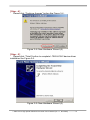
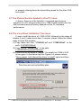
6.8 The Long Driver Installation Time Issue
If users install the driver of I-7565-H1/H2 followed by the steps of
chapter 3 and it takes more than 2 minutes, please follow the below
steps to solve this problem.
(1) Copy these two files, “I-7565-H1.inf” and “I-7565-H2.inf”, to the
path: C:\WINDOWS\inf\.
(2) Copy the file, “usbser.sys”, to the path:
C:\WINDOWS\system32\drivers\.
(3) Please follow the steps in chapter 3 to install the I-7565-H1/H2
driver again. In the below step like Figure 6-4, please choose
“Don’t search. I will choose the driver to install” option and then
click “Next” button.
I-7565-H1/H2 High Speed USB/CAN Converter User’s Manual (Ver 1.1, Nov/2009) ------------- 67
Figure 6-4: Driver Installation of I-7565-H1/H2 (1)
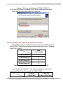
(4) When the Figure 6-5 shows, click “Next” button and the other
steps are the same with those in chapter 3.
Figure 6-5: Driver Installation of I-7565-H1/H2 (2)
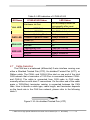
6.9 The Supported CAN Filter-ID Number Issue
The total capacity for CAN Filter-ID provided by I-7565-H1/H2 is
440 WORD. The following table describes the size of every different
type CAN Filter-ID.
Size
(Unit: WORD)
11-bit Single ID
1
11-bit Group ID
2
29-bit Single ID
2
29-bit Group ID
4
Table 6-1: Size of Every Different Type CAN Filter-ID
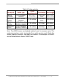
According to the Table 6-1, the following table describes the
supported CAN Filter-ID number of I-7565-H1/H2.
I-7565-H1
( CAN Port )
I-7565-H2
( Each CAN Port )
I-7565-H1/H2 High Speed USB/CAN Converter User’s Manual (Ver 1.1, Nov/2009) ------------- 68
11-bit Single ID
440/1 = 440
220
11-bit Group ID
440/2 = 220
110
29-bit Single ID
440/2 = 220
110
29-bit Group ID
440/4 = 110
55
Table 6-2: size of every different type CAN ID
6.10 Other Issue
In general, the following errors could also occur. For example,
CAN media connection problem, terminal resistor problem, different
baud rate configuration with CAN network and so on.
I-7565-H1/H2 High Speed USB/CAN Converter User’s Manual (Ver 1.1, Nov/2009) ------------- 69
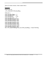
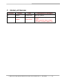
7. History of Version
Version
1.0
1.1
Author
Edward
Edward
Date
Description of changes
22-Sep-2009
The First Version
25-Nov-2009
1. Modify the connection screen of
Utility.
2. Add connection issue content.
3. Provide Firmware Update Tool.
I-7565-H1/H2 High Speed USB/CAN Converter User’s Manual (Ver 1.1, Nov/2009) ------------- 70