1
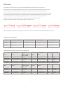
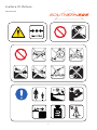
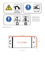
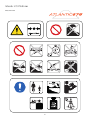
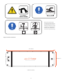
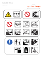
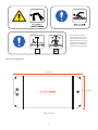
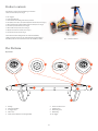
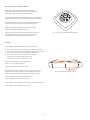
Platforms
Important information
It is the responsibility of the owner of this product to read the instruction manual and instruct
all users in the safe operation of this product and its accessories.
Please read this instruction manual carefully prior to using this Product. Follow instructions while operating this Product. This
safety manual is an integral part of the Product and should remain with the Product in the event that it is re-sold or transferred to
a third party. NautiBuoy marine retains the right to modify the safety manual as is deemed appropriate and it is your responsibility
to familiarise yourself with any modifications. Please refer to our website www.nautibuoymarine.com for updates.
Each Platform size has a different number of users and maximum load. It is important that you
familiarise yourself with the specific warnings for your platform size
Read instructions first
2
Warnings
Disclaimer
It is not possible for NautiBuoy Marine to warn you about every
possible danger related to the use of the Product. Please use
your own good judgement when operating this Product.
5. Installation of this Product
Follow carefully the instructions provided by this Manual
to operate and install this Product, failure to do so
could lead to serious bodily injury or death.
The warnings and practices set forth below represent some common
risks encountered by users and does not purport to cover all instances
of risk and danger. Please use this Product with common sense.
Always install and carry this Product as a team of two or more persons.
Failure to do so could lead to serious bodily injury or death.
1. General Warnings
• This Product provides no protection against drowning
• This Product is not a life saving device
• This Product is not a flotation device
• This Product is in no case PPE (Personal Protective Equipment)
User should never use an air compressor to inflate this
Product. Use of an air compressor may cause the Product to
burst and could lead to serious bodily injury or death.
6. General use of this Product
Users should be careful while operating or using this Product.
Do not use this Product in one of the following manner, such
use could lead to serious bodily injury or death:
• Always remove personal items such as rings, watches
or other sharp objects before using this Product
• NautiBuoy recommends the use of life jackets
(PFD), for all persons using this Product
• Always take care when stepping onto the
Platform from another vessel/object
• Never jump on or onto this Product
• Do not swim underneath this Product
• Do not swim through or place any body parts
though any element of this Product
• Always take extreme care when swimming
between the shore and this Product
• While using this Product, pay attention to any other
water users or boat traffic. These may create a wash
and cause the Product to move unexpectedly
• Never use whilst in between 2 yachts in harbour
• Always take extreme care when using in harbours
2. Weather Conditions
• Do not use this Product in poor weather conditions, including
high and off shore winds, waves, strong or off shore currents or
lightning. This may cause the Product to move unexpectedly or
turn over and could lead to serious bodily injury or death
• Do not use this Product at night, under low light or in
poor visibility conditions, including in white water. Such
use could lead to serious bodily injury or death
3. Location of this Product
This Product is solely intended to be used in calm water and under great
weather conditions. Do not use this Product in one of the following
locations, such use could lead to serious bodily injury or death:
• Do not use this Product in shallow water, waves or
swell or where other water users are located. This may
cause the Product to move unexpectedly or turn over
and could lead to serious bodily injury or death
• Do not use this Product further than 82 feet / 25
meters from the shore or in obstructed area
• Do not use this Product close to submerged rocks and sand bars
or where jellyfish, sharks or other dangerous animals are known to
be present. Such use could lead to serious bodily injury or death
• Do not use this Product in recreational swimming pools or on dry land
7. Specific use of the Product
Towing:
When towing this Product, users should follow operating
instructions located on page 18, failure to do so
could lead to serious bodily injury or death;
• Never tow this Product whilst persons are on board, it could cause
the persons to fall and lead to serious bodily injury or death
• Never tow when the Ballast Bags are full, it could cause
damage to the Product or to the towing vessel
4. User of this Product
Do not use this Product in any of the following circumstances,
such use could lead to serious bodily injury or death:
• Never exceed the maximum number of users for each platform size
• Never exceed the maximum load for each Platform size
• Non-swimmer and persons with difficulty
swimming should never use this Product
• People unsure of their capacity to swim, injured or not
physically able to swim should never use this Product
• Never operate or use the Product whilst under
the influence of alcohol or drugs
• Children should never use this Product without adult supervision
• Children should always wear a life jacket while using this Product
• Children should never be left unattended when using this Product
• Elderly should be assisted when using this Product
Jet-ski dock:
Never remain on, swim near or around this Product when jetskis are in operation. It could cause a collision with a jet-ski
or bodily parts to get trapped between the jet skis and the
Platforms and lead to serious bodily injury or death
• Always approach the Product on the jet-ski at the
slowest speed possible. Failure to do so may result in a
collision and lead to serious bodily injury or death
• When on a jet-ski, always pay attention for loose straps or dock
lines floating near the Platforms. Failure to do so may cause a
collision with the jet-ski and lead to serious bodily injury or death
3
Contents
Warnings
3
To Uninstall
21
1. General Warnings
2. Weather Conditions
3. Location of this Product
4. User of this Product
5. Installation of this Product
6. General use of this Product
7. Specific use of the Product
3
3
3
3
3
3
3
Stage 1: Emptying the Ballast Bags
Stage 2: Removing the Product from the water
Stage 3: Platform deflation and storage
21
21
22
Platforms
5
Table of inflation recommendations
Table of different sizes, weights, maximum no of users and max load 5
5
Arctic 375 Platform
6
Safety information
Diagram of Arctic 375 Platform
6
7
Southern 525 Platform
8
Safety information
Diagram of Southern 525 Platform
8
9
Atlantic 675 Platform
Safety information
Diagram of Atlantic 675 Platform
Pacific 800 Platform
Safety information
Diagram of Pacific 800 Platform
Floating Island
Stage 1: Towing the Product:
Stage 2: Anchoring the Product:
Stage 3: Returning the Platform to the vessel
Connection of two Products
24
24
25
25
26
10
Air Toggle size guide table SIDE BY SIDE LINKING ONLY 26
Stage 1: Choosing a configuration
27
Stage 2: Preparation of the Platforms
28
Stage 3: Connecting a second Product in your desired configuration 28
End-to-End Configuration
28
How to feed the Air Toggle through and inflate using the Stirrup pump 29
Jet-Ski dock configuration (T–Shape)
30
L-Shape Configuration
31
Side-by-side configuration 32
Side-by-side configuration Air Toggle length table
32
Stage 4 :To uninstall the connected Products
33
10
11
34
Care and Maintenance
12 Technical Specifications
12
13
Repairing your Product
Product contents
The Platform
14
Key features
Multi-purpose Platform Mountings (MPM’s)
Air Toggles
14
15
15
To Operate
To Install
16
Stage 1: Inflating the Platform
Stage 2: Inflating the Air Toggles
Stage 3: Preparing the Ballast Bags to fill
Stage 4: Securing the Product to the vessel
Stage 5: Deployment of the Product in water
Stage 6: Attachment of accessories
16
18
19
19
20
20
NautiBuoy Inflatable repair’s guide for Hypalon and PVC
Finding your air leak
Repairing your leak
Working environment
Fabric types
Fabric repair patches
For emergency repairs
Materials and tools required
Different types of repairs
Repairing Hypalon & PVC
Repairing CR /CR dropstitch
Completing emergency repairs with Tear Aid
Replacing Halkey Roberts Valves
Disclaimer
14
16
4
35
35
35
35
35
35
35
36
36
36
36
36
37
37
37
37
Platforms
Congratulations on purchasing your new multi-functional inflatable Platform, designed for the luxury Super Yacht.
This Platform has been carefully designed by yachtsman for yachtsman and manufactured using the best quality Orca drop stitch
and CSM Hypalon, as well as German PVC for the Air Toggles. They are built to withstand the harsh marine environment.
The Product has been designed with your safety in mind and complies with strict European safety standards (EN 15649- 1-2-3:2012 ).
Any activity on the water can be safe and fun for all. The operator’s manual has been provided to help ensure you enjoy the Product
in safety. It is intended to alert you to some of the potentially dangerous conditions that can arise by using the Product.
The next pages have specific safety information for the range of Platform sizes. It is important that you
familiarise yourself with the specific warnings and information for your Platform size
Due to design changes and improvements, the figures present in the manual may not exactly depict the product purchased by the consumer.
Table of inflation recommendations
Product
Minimum pressure required
Maximum pressure permitted
OV10 pump capability
Stirrup pump capability
Platforms
3.0psi/206mb
5.5psi/379mb
3.6psi/250mb
5.5psi/379mb +
Air Toggles
2.0psi/138mb
5.5psi/379mb
3.6psi/250mb
5.5psi/379mb +
Table of different sizes, weights, maximum no of users and max load
Inflated Dimension
Metric
Approximate
Inflation/ Deflation
time to 250MB
Max number
of Users
Stowage Dimensions
Metric
Weight (kg)
Max Load (kg)
Name
Arctic 375
2.5m x 1.5m x 20cm
1m 30 secs
4
155cm x 30cm x 30cm
22kg
410kg
Southern 525
3.5m x 1.5m x 20cm
1m 40 secs
5
165cm x 32cm x 32cm
32kg
480kg
Atlantic 675
4.5m x 1.5m x 20cm
2m 40 secs
7
165cm x 35cm x 35cm
36kgs
600kg
Pacific 800
4m x 2m x 20cm
3m 30secs
8
220cm x 35cm x 35cm
40kgs
700kg
Inflated Dimensions
Imperial
Approximate
Inflation/ Deflation
time to 3.6psi
Max number
of Users
Stowage Dimensions
Imperial
Weight (lbs)
Max Load (lbs)
Name
Arctic 375
8ft 2”x 4ft 11” x 8”
1m 30 secs
4
61” x 12” x 12”
48lbs
903 lbs
Southern 525
11ft 5.5” x 4ft 11” x 8”
1m 40 secs
5
64” x 13” x 13”
70lbs
1058 lbs
Atlantic 675
14ft 9” x 4ft 11” 8”
2m 40 secs
7
64” x 13.7” x 13.7”
79lbs
1322 lbs
Pacific 800
13ft 1” x 6ft 6” x 8”
3m 30secs
8
86” x 13.7” x 13.7”
88lbs
1543 lbs
5
Arctic 375 Platform
Safety information
100%
6
Because this device would
not meet the requirements of
tests described in 4.3.2.2.2. of
EN15649-3:2012 it can not be
classified as providing floating
stability and is classified as a
device that requires balancing.
Diagram of Arctic 375 Platform
2.5m (8ft 2")
1.5m (4ft 11")
200mm (7.8”) Deep
7
Southern 525 Platform
Safety information
100%
8
Because this device would
not meet the requirements of
tests described in 4.3.2.2.2. of
EN15649-3:2012 it can not be
classified as providing floating
stability and is classified as a
device that requires balancing.
Diagram of Southern 525 Platform
3.5m (11ft 5.5")
1.5m (4ft 11”)
200mm (7.8”) Deep
9
Atlantic 675 Platform
Safety information
100%
10
Because this device would
not meet the requirements of
tests described in 4.3.2.2.2. of
EN15649-3:2012 it can not be
classified as providing floating
stability and is classified as a
device that requires balancing.
Diagram of Atlantic 675 Platform
4.5m (14ft 9")
1.5m (4ft 11”)
200mm (7.8”) Deep
11
Pacific 800 Platform
Safety information
100%
12
Because this device would
not meet the requirements of
tests described in 4.3.2.2.2. of
EN15649-3:2012 it can not be
classified as providing floating
stability and is classified as a
device that requires balancing.
Diagram of Pacific 800 Platform
4m (13ft 1")
2m (6ft 6")
200mm (7.8”) Deep
13
Product contents
Each Platform comes with the following as standard
and form the Product parts (Fig 1):
4
2 x Air Toggles
1 x Instruction Manual
1 x Stowable Protective Bag with interior pockets
2 x 8m (26ft), 14mm (0.5”) eye spliced polyester dock lines (no:1 in Fig 1)
1 x Bravo OV10 Pump 3.6psi/250mb (230V or 120V) (no:2 in Fig 1)
2 x Suction Cups with Cleats (no:3 in Fig 1)
1 x Bravo SUP Stirrup Pump (no:4 in Fig 1)
1 x Repair kit with instructions (no:5 in Fig 1)
2 x Connection Straps (no:6 in Fig 1)
2
1
3
5
6
This Product has been designed for use with the NautiBuoy
Ladder and other accessories. For safe installation of the Platform,
NautiBuoy Marine recommends the use of the NautiBuoy Ladder.
Fig 1 – Product contents
The Platform
Key features
5
6
7
5
4
1
10
2
8
3
9
1.
2.
3.
4.
5.
D-Rings
Horizontal Handles
Air Toggle loops
Velcro strip
Multi-purpose Platform mountings (MPM)
6. Pressure release valve
7. Inflation valve
8. Ballast Bag strap
9. Ballast Bag
10. Air Toggle
14
Multi-purpose Platform Mountings (MPM’s)
The Platform comes as standard with three Multi-purpose
Platform Mountings (MPMs) (Fig 2). These are located at either
end of the Platform as seen on the diagram on page 14.
The Multi-purpose Platform Mountings (MPMs) can accommodate and
lock in multiple accessories, including the hose holders and the ladders.
Occasionally the locks, after heavy use, can break. Replacement parts
and spares can be purchased by contacting NautiBuoy Marine.
Only use bolts provided by NautiBuoy. Bolts that are longer,
will pierce the inflatable voiding the warranty.
Information on the operation of the MPM compatible accessories
is available within the relevant accessory manual. Manuals are
also available on our website www.nautibuoymarine.com.
Fig 2 – Multi-purpose Platform Mounting (MPM)
Air Toggles
The Air Toggle’s have been designed to serve several purposes.
1. They provide a second and third chamber to the Platform for safety.
2. They allow the Platforms to be connected to each other in both T-shape
and L-shape as well as end-to-end and side-by-side (page 27).
3. They can be used with the Transom Bumpers to prevent
the Platforms from floating under high transoms
(please reference the Transom Bumper manual).
Positioned strategically around the edges of the
Platforms, are Air Toggle loops (Fig 3).
These are fastened by 2 Velcro straps (Fig 3).
Always ensure that all Air Toggle straps that are not being used are
kept fastened by the Velcro. These may cause a tripping hazard whilst
inflating or using the Platform and entanglement whilst in the water.
Fig 3 – Air Toggle loops and Velcro straps
These are not designed for lifting of the Platform and
are for Air Toggle and Ladder support use only.
Always lift the platform using either the D-Rings or the Horizontal Handles.
For Air Toggle operating instructions see page 20.
15
To Operate
Operation of this Product requires two or more people.
To Install
The following Stages 1 to 5 are to be performed
before this Product is deployed in water.
In the event you want to connect two Products (page 26), ensure that
the first Product to be deployed is the one to be secured to the vessel.
Stage 1: Inflating the Platform
Fig 4 – Remove Platform from bag
1. Choose a location where the Platform can be unrolled onto a dry
surface, free of grease, liquids or sharp objects, with access to an
electrical outlet or extension cord. Ideally the set up should be
somewhere near to the water’s edge where you intend to launch.
The space required is dependent upon your chosen Platform size.
Arctic 375
Southern 525
Atlantic 675
Pacific 800 2.5m x 1.5m x 20cm.
3.5m x 1.5m x 20cm.
4.5m x 1.5m x 20cm.
4m x 2m x 20cm.
Arctic 375
Southern 525
Atlantic 675
Pacific 800 8ft 2”x 4ft 11” x 8”.
11ft 5.5” x 4ft 11” x 8”.
14ft 9” x 4ft 11” 8”.
13ft 1” x 6ft 6” x 8”.
Fig 5 – Unroll Platform
2. Once in position, remove the Platform from the bag (Fig 4) and
unfold completely (Fig 5), locating the main inflation valve (Fig 6).
3. Remove the cap from the inflation valve by twisting anti clockwise (Fig
6) and ensure the one way valve is shut (Fig 8) by pressing the white
button in the centre of the valve until it pops out (Fig 7 and Fig 8).
Warning
Ensure the OV10 electric pump is not used whilst the user or the
pump are wet or in close vicinity to water as it may produce electric
shock which could lead to serious bodily injury or death.
Fig 6 – Inflation valve with cap on,
remove cap anti-clockwise
NEVER use an air compressor to inflate any NautiBuoy
products. Air compressors are designed for high pressure
inflation and can cause inflatable products to burst.
Excessive high pressure during inflation can seriously
damage the product and may void the warranty.
NautiBuoy Marine recommend that the supplied OV10 pump
is used to inflate the Platform. Please read the OV10 Pump
product manual carefully before inflating the Platform.
Fig 7 – One way Inflation valve open (release air)
The approximate inflation times to 3.6psi/379mb are as follows:
Arctic 375
1 minute 30 seconds.
Southern 525
1 minute 40 seconds.
Atlantic 675
2 minutes 40 seconds.
Pacific 800 3 minutes 30 seconds.
Please see the inflation recommendation table on page 5.
Allowances need to be made when inflating in hot climates as air expands.
Fig 8 – One way Inflation valve shut (retain air)
16
4. Before plugging to an AC socket, ensure that the Bravo OV10
pump is in inflate mode (Fig 9). The pump is clearly marked
OUT where the inflation hose must be attached for inflation,
ensure it is in this position before following the next step.
5. Insert the nozzle end of the Bravo OV10 pump into the inflation
valve and rotate the nozzle clockwise until firmly in place.
6. Do not sit or stand on the Platform when inflating it. This would
apply unusual pressure that may damage the pump and the
Platform. Once the Platform is cleared, switch on the Bravo OV10
Pump and inflate the Platform until it gives a higher pitched
noise. Once you hear the higher pitched noise, switch the Bravo
OV10 Pump off. Do not leave the pump running unattended.
7. Remove the nozzle of the pump from the inflation valve by turning
anti-clockwise and unplug the Bravo OV10 Pump from the AC socket.
8. To obtain an even more rigid Platform, users can use
the stirrup pump provided to further inflate.
9. The Platforms should be firm and rigid when correctly inflated.
10. Check for the correct air pressure by using a manometer (not provided)
or using the pressure gauge supplied on the Stirrup pump (Fig 11).
Fig 9 – Inflate (marked OUT on pump)
Using the Stirrup pump to check Air pressure
• To check the air pressure using the Stirrup pump, first ensure it
is in Inflate mode by checking the inflation hoses is connected
to where it is clearly marked ‘OUT’, attach the Stirrup pump
with the nozzle into the inflation valve by turning clockwise
• Pump the handle of the Stirrup pump in a vertical motion
and the pressure will show on the gauge. Begin to inflate the
platform and whilst doing so, read the air pressure on the
pressure gauge located at the top of the stirrup pump.
Fig 10 – Deflate (marked IN on pump)
Using a Monometer
If using the Monometer (not provided) follow the instructions of the
manufacturer to check the Pressure. When finished, remove the
Manometer and either replace the main inflation valve protective
cap (Fig 12), continue inflating with either the Bravo OV10 pump
or the Stirrup pump depending upon your desired pressure.
Steps 5 to 9 are to be repeated if the air pressure in
the platform is lower than 3.0psl/206mb.
Fig 11 – Use pressure gauge found on SUP pump
11. This step is not mandatory if the Platform is firm and rigid as you
please, go to Step 17 relating to the valve cap. However if you
need to add more pressure to the Platform this can be done so
with use of the stirrup pump explained in the following steps
12. Ensure the Stirrup pump is in inflate mode by checking the
inflation hose is connected to where it is clearly marked ‘OUT’.
13. Insert the nozzle end of the Stirrup pump into the inflation valve
and turn clockwise until firmly connected. It will lock into place.
14. Using the handle on the Stirrup pump, begin to add air
by pumping the handle up and down in a vertical motion,
ensuring legs are bent and back is straight.
15. As more air is added, the pressure gauge dial situated
at the top of the Stirrup pump will begin to rise.
16. Once 5.5Psi has been achieved, the pressure release valve on the
platform will begin to hiss allowing no more pressure to be added.
17. When finished, remove the Stirrup Pump by turning the
nozzle anticlockwise and replace the main inflation valve
protective cap to help ensure air tight integrity (Fig 12).
18. Once the main body of the Platform has been inflated, the
user must attach the Air Toggle’s to provide a 2nd and 3rd
air chamber for safety (see page 18 for instructions).
Fig 12 – Inflation valve with cap
on, replace cap clockwise
17
Stage 2: Inflating the Air Toggles
1. Inflate one Air Toggle at a time following the steps below.
2. Undo the Velcro fastenings on the Air Toggle loops you require
to use at either end or on either side of the Platform (Fig 13).
Always keep the Air Toggle loops not in use securely fastened.
3. Feed the Air Toggle into the chosen open Air Toggle loops (Fig
14) ensuring the Air Toggle loop isn’t twisted (Fig 16).
4. Also ensure that the actual Air Toggle isn’t twisted (Fig 15) and
is positioned centrally (Fig 18) rather than off centre (Fig 17).
5. Check that the Air Toggle is in place (Fig 14)
Fig 13 – Undo Velcro straps
Warning
• Never use an air compressor to inflate the Air Toggles. Air compressors
are designed for high pressure inflation and can cause Air Toggles
products to burst. Excessive high pressure during inflation can
seriously damage the product and may void the warranty.
• Never inflate the Air Toggle with an OV10 electric pump,
this could lead to serious bodily injury or death.
Fig 14 – Feed Air Toggle through loops
6. Prepare the inflation valves for inflation by pressing the
white button in the centre of the valve until it pops out.
Failure to do so will cause immediate deflation.
7. Use the Stirrup pump provided to inflate the Air Toggle’s
(Fig 18). Never inflate with electric Bravo OV10 pump.
Using the stirrup pump to Inflate the Air Toggles
a. First ensure the Stirrup pump is in inflate mode. Check the
inflation hose is connected where it is clearly marked ‘OUT’.
b. Insert the Nozzle end of the stirrup into the main air valve on
the Air Toggle and turn clockwise until firmly connected.
c. Using the handle on the stirrup pump, begin to add air by pumping
the handle up and down in a vertical motion, ensuring legs are bent
and back is straight and feet are on the bottom of the pump.
d. As more air is added, the pressure gauge dial situated
at the top of the Stirrup pump will begin to rise.
e. Once 5.5Psi has been achieved, the pressure release
valve on the Air Toggle will begin to expel air.
f. After use, place the cap of the inflation valve back on the Air Toggle. It
provides an extra seal for the valve to help maintain air tight integrity.
Fig 15 – Do not twist Air Toggle
Fig 16 – Do not twist Air Toggle loop
8. Repeat the process for the second Air Toggle (3rd chamber).
Ensure both Air Toggles are used on the Platform for safety.
Further options
If this Product is not to be towed to an anchorage, please go to Stage 3.
If this Product is to be towed to an anchorage, please
disregard the following instructions and go straight
to floating island configuration (page 24).
Fig 17 – Position centrally, not like this
Fig 18 – Inflated Air Toggle
18
Stage 3: Preparing the Ballast Bags to fill
If the Platform is to be towed to an anchorage then please go straight
to floating island configuration on page 24 and follow the steps.
The Ballast Bags have been designed to provide the Platform
with fantastic stability whilst it is floating in the water.
It is important to ensure that the Ballast Bags are full before
users are on board the Platform to prevent capsize.
Fig 19 – Ballast Bag up
To ensure the Ballast Bags will fill with water once the Platform
has been deployed it is important to follow these steps
These steps must be followed before the
platform is deployed to the water.
1. Place each Ballast Bag in the down position by removing the Ballast
Bag strap from the Velcro strip on top of the Platform (Fig 19).
2. Deploy the Ballast Bags and reattach the Velcro straight
5cm/2” from the end of the Platform (Fig 20).
3. Ensure each Ballast Bags is in the down position and able
to fill (Fig 20) and ensure the Velcro straps are secure.
Fig 20 – Ballast Bag down
Stage 4: Securing the Product to the vessel
Warning
It is essential that the Product is securely attached to the vessel before
use, failure to do so could cause the Platform to float free from the
vessel. Nautibuoy is in no way responsible for any damage, injuries
or losses due to improper securing the Product to the vessel.
Check weather conditions and forecasts prior to securing the Product
to the vessel. Do not use in bad weather conditions and heavy
swells, such use could lead to serious bodily injury or death.
1. Ensure a dock line is attached securely to the Platform
using one of the four D-rings using a cow hitch.
2. Before deploying the Product, ensure the loose end of the Dockline is
attached securely to a solid cleat on the vessel using the OXO method.
Tying a cow hitch
1. Push spliced loop of Dock Line through the stainless D ring (Fig 21).
2. Pass the other end of the Dock Line through the spliced loop (Fig 22).
3. Pull all the of the remaining Dock Line through
the spliced loop until it is tight (Fig 23).
Fig 21 –
Cow hitch step 1
Fig 22 –
Cow hitch step 2
Fig 23 –
Cow hitch step 3
Fig 24 –
OXO method step 1
Fig 25 –
OXO method step 2
Fig 26 –
OXO method step 3
OXO method
1. Make one full turn around the cleat in a clockwise direction
and pull tight (Fig 24).
2. Then on top of the full loop make a figure of eight and pull tight (Fig 25).
3. Make one more full loop in a clockwise direction and pull
tight, for added security add one more full loop (Fig 26).
Warning
When using the NautiBuoy Suction cup to fasten along
side vessel, ensure you also have a fixed line to vessel in
case the Suction Cup fails or the knots unfasten.
For full instructions on the use of the NautiBuoy Suction Cup
and NautiBuoy Dockline please refer to their packaging or
alternatively they can be found on www.nautibuoymarine.com
19
Stage 5: Deployment of the Product in water
1. Never drag the Product. Always lift using the horizontal handles or
the D-rings provided to avoid any accidental tearing or abrasion.
2. To deploy the Platform, have at least 2 people evenly spaced
around it to carry it and simply lift the Platform into the water.
3. Do not board the Product before the Ballast Bags are
full. Once the Platform has been deployed, allow at least 1
minute for the Ballast Bags to fill with water. Before boarding
the Platform, double check all 4 Ballast Bags are full.
4. We recommend that the Ladder be installed before
boarding to allow users an easier exit from the water.
Please see the Ladder manual for instructions.
If you are attaching accessories, please follow instructions
provided in the Stage 6 ‘Attachment of accessories’ below. In the
alternative, Congratulations, the Product is ready for use!
While using the Product, periodically check its inflation by
using a manometer (not provided) or using the pressure gauge
supplied on the Stirrup pump. Pressure will change during the
day due to expansion of air in heat. Pressure will be greatest
during maximum expansion during the hottest part of the day. If
pressure is too low, use the stirrup pump to inflate the Product.
If extra air is required to top up the pressure on either the Platforms or
Air Toggles, users must never use the electric Bravo OV10 air pump whilst
on the water. Always use the Stirrup pump provided. Follow Platform
and Air Toggle inflation instructions using a manual Stirrup pump.
Stage 6: Attachment of accessories
Once the Platform has been deployed, you can start
to add the various accessories offered by NautiBuoy
Marine, depending on the intended function.
Always follow the instructions provided with accessory
manual for installation before using.
Do not use before having read and understand the safety information.
Please check our website for a full list of available accessories.
20
To Uninstall
Stage 1: Emptying the Ballast Bags
The grey ballast bag straps allow the user to manually empty the Ballast
Bags, so the Platform can be easily lifted from the water after use.
When the Platform is ready to be taken out of the water,
the grey ballast straps need to be pulled and attached
in the up position in the following manner.
Warning:
Care must be taken on the Platform, once the ballast has been emptied
as the Product will become unstable and could slide on the water.
Do not stand on the Product while emptying the Ballast Bags.
Fig 27 – Never empty ballast while standing
1. Get into a kneeling or seated position where you can reach the top of
the strap easily. Never stand whilst emptying the Ballast Bags (Fig 27).
2. Release the top of the strap from the Velcro strip on top of
the Platform (Fig 28).
3. Pull the strap all the way up until you see the lower
piece of Velcro positioned near the ballast bag.
4. Attach the lower Velcro securely onto the Velcro strip on the
top of the Platform (Fig 29).
5. The ballast bag will now be empty and pressed against the side
of the Platform (Fig 29).
6. Repeat the process for all four Ballast Bags.
7. Care must be taken whilst on the Platform and when
transferring from the Platform to the vessel.
Fig 28 – Release Velcro strap whilst kneeling
Stage 2: Removing the Product from the water
Once all the water has been emptied from the Ballast
Bags the Platform can be removed from the water.
1. Ensure all four Ballast Bags are in the up position and the straps
are securely attached to the Velcro strips on top of the Platform
2. Have at least 2 people evenly spaced around the
Platform to easily lift it out of the water.
3. Once the Product is safely on board, the dock line can be released.
4. Remove the Dockline from the cleat by following the OXO method
on page 19 in reverse, once this end of the Dockline is free,
remove the Dockline from the platform D-ring by following the cow
hitch instructions in reverse on page 19. For full instructions
on using the NautiBuoy Dockline please refer to the packaging or
alternatively they can be found on www.nautibuoymarine.com.
5. Always rinse the Products after every use with soap and fresh water,
then allow to dry. Prolonged exposure to salt water can damage and
may shorten the expected lifetime of the Product. To reduce these
risks regularly clean and rinse the Product with fresh water and
dry before storing. For full instructions on the care of your Product
please refer to the Care and Maintenance section on page 34.
Fig 29 – Attach Velcro strip to top of Platform
Do not deflate any part of the Product before the Product is cleaned
and dried. See Care and Maintenance section on page 34.
21
Stage 3: Platform deflation and storage
Before deflating the Product or plugging the Pump, ensure
that the user, the pump and the Product are dry and not
in close vicinity to water as it may produce electric shock
which could lead to serious bodily injury or death.
We recommend, for quicer deflation, that the Bravo OV10 pump be used
for this process. The Stirrup pump can be used however, it will take longer.
Fig 30 – One way inflation valve open to release air
Please read the Bravo OV10 pump product
manual before deflating the Platform.
1. Always ensure the Product is put away clean and dry.
2. Lie the Platform out on a clean, dry and grease free surface.
3. Deflate both Air Toggles by pressing the white button in the centre of
the valve until it stays down (Fig 30). The air will then be released.
4. Remove the Air Toggles from the Air Toggle loops and allow
the loops to dry before securing back with the Velcro.
5. Before plugging in the OV10 pump, ensure that the pump is
in deflate mode. The pump is clearly marked IN where the
inflation hose must be attached for deflation (Fig 31). For full
instructions see the Bravo OV10 pump user manual.
6. Plug the Bravo OV10 pump into your AC socket. Fit the end
nozzle of the pump into the platform inflation valve and
rotate the nozzle clockwise until it is firmly in place.
7. Switch on the pump and deflate the platform. Switch off the
pump once all the air has been removed from the platform.
It is important to remove all the air from the chamber as any
air left may freeze and cause damage to the platform.
8. Make sure the Air Toggles are completely deflated and
dry and ensure the valve caps securely shut.
9. The Ballast Bag strap Velcro should be connected to the Velcro strip
on the Platform in either the up or down position before rolling.
10. Lay the two deflated Air Toggles across the Platform at the opposite
end to the inflation valve. This is important so any excess air can be
pushed out as you roll the Platform (Fig 32). Position the Air Toggles
so they are laid over the multi-purpose Platform mounts (MPM’s),
by doing this you protect the foam from any marks or dents.
11. As you roll the platform up, position the Ballast Bags so
they are flat against the rolled platform (Fig 33).
12. Starting at the end containing the Air Toggle’s, roll the Platform
around the Air Toggles from one end to the other, making
sure the roll is straight and as tight as possible (Fig 33).
13. It is important to roll the Platform to protect the foam from any damage
or creases. NEVER fold the Platform. This can damage or crease the
foam which could affect the aesthetics and functionality of the foam.
14. Ensure to close the inflation valve on the Platform to
prevent air from leaking back into the chamber.
Fig 31 – Deflate (marked IN on pump)
Fig 32 – Two deflated Air Toggles placed over MPMs
Fig 33 – Roll towards inflation valve
22
15. Once the platform has been fully rolled it can be placed back into the
bag, before doing so ensure the bag is fully open with the pockets
facing out see (Fig 36). NEVER store uncovered or out of the bag.
16. ALWAYS make sure that at least 2 people are spaced evenly
around the platform to lift it back into the bag.
17. Once the platform is back in the bag, tuck the orange
pockets back on top of the platform (Fig 38) and
reseal the bag along the Velcro strip (Fig 39).
18. Store the Platform in a clean dry location, out of direct
sun light and away from any sharp objects or harmful
chemicals or products i.e. batteries. Never store in
temperatures below 40 Fahrenheit / -4 Celsius.
Fig 34 – Continue to roll towards inflation valve
Storing your platform
Avoid storing the product whilst it is damp. This will prevent mildew
forming and stop the Platform from smelling unpleasant.
Always store in the bag provided.
The Teak foam surface must be handled with care. Ensure never to
fold it and always roll the Platform to avoid creasing. Never drag
sharp items over the surface. This will tear or scratch the foam.
Fig 35 – Finished roll
Never store your platform near chemicals or corrosive products.
Fig 36 – Lay pockets outside of empty bag
Fig 37 – Place rolled Platform in the bag
Fig 38 – Tuck the pockets into the bag on top of the Platform
Fig 39 – Close the bag
23
Floating Island
Warning
Due to the wide range of conditions, we advise using a
professional mariner, skilled in anchoring and mooring
procedures who has researched the local conditions.
the dangers of rope recoil. Keep all passengers away from the rope
whilst towing to avoid becoming entangled or hit by the rope.
• Always ensure all persons wear a suitable Government approved life
jacket required by local authorities, whilst in the vessel towing.
• Ensure to keep the tow rope away from the moving propeller.
• ALWAYS SHUT OFF ENGINE AND REMOVE KEY BEFORE
RETRIEVING ROPE. ALWAYS USE AN ENGINE KILL CORD.
Improper anchoring may result in the product moving
anchor or floating away. This could lead to serious bodily
injury or death. NautiBuoy is in no way responsible for any
damage, injuries or losses due to improper anchoring.
You will need the following:
1. Choose a suitable anchor and line (not provided by NautiBuoy Marine).
NautiBuoy Marine recommends the use of an anchor weighing
45kgs/100lbs and on windy water ways or with tidal current, a heavier
anchor (90kgs/200lbs) The line must be adequate enough for the load.
2. Towing Bridle (not provided by NautiBuoy Marine)
3. Suitable towing vessel (not provided by NautiBuoy Marine)
4. Platform
5. 2x Air Toggles
6. Stirrup pump
7. Any chosen accessories (Available for separate purchase)
Check weather conditions and forecast before using the Product
as a floating island. Do not use in bad weather conditions,
such use could lead to serious bodily injury or death;
• Never exceed 5 knots whilst towing the Product behind
a vessel. This can cause damage to the towing vessels
towing bridle or to the Platform anchor point.
• Never tow the Product whilst persons are on the Product.
• Never tow the Product when the Ballast Bags are in the down
position, this will create drag potentially causing damage
to the anchor point, Ballast Bags or towing bridle.
• Tow ropes stretch when is use. If a tow rope snaps, it could snap
back into the vessel towing. Ensure all passengers are warned of
Stage 1: Towing the Product:
Fig 40 – reinforced anchor point on the underside of the Platform
Having followed the instructions of Install Stage 1 (page
16). Please follow these next steps if you wish to tow
your Product to a different location or anchorage.
The Platform has a reinforced anchor point on
the underside ideal for towing (Fig 40).
1. Ensure the Ballast Bags are empty, in the up position and with the strap
held securely in place to the Velcro strips on top of the Platforms (Fig
41). See Stage 1 Empting Ballast Bags (page 21) for full instructions.
2. Ensure that the ballast bag straps are secured their entire length to
the Velcro strips on top of the Platform. This can be done by tucking
the top end of the strap under the opposing ballast strap (Fig 41).
Fig 41 – Ballast bags empty and secured to the Platform
3. It is very important that the straps are secure before and during
towing. Failure to do so could result in the Ballast Bags filling,
causing damage to the Platform or to the towing vessel.
4. The Platform has a reinforced anchor point on the underside,
ideal for towing (Fig 40). This is positioned at the opposite end
of the inflation valve, directly under the single MPM fitting.
5. Ensure the towing vessel has an adequate bridle and tow line set up
in an approved fashion for the tow. Please refer to your watercraft
manual for instructions on proper tow rope attachment.
6. Attach a bridle to the anchor point at one end of the Platform,
using a proper tow rope for this activity (Fig 42).
7. Tow the Product to your chosen location.
Fig 42 – Tow line attached to anchor point on underside of Platform
24
Stage 2: Anchoring the Product:
Stage 3: Returning the Platform to the vessel
It is important to anchor the Product correctly for the safety of the users
and the Product. Always check the security of the anchor before use.
1. Secure the towing vessel to the Platform tying the painter
with a bowline to one of the Platform D-rings and ensure
the engine of the towing vessel is switched off.
2. Board the Platform from the towing vessel carefully.
3. Remove any accessories from the Product
and place in the towing vessel.
4. Deflate both Air Toggles by pressing the white button in the centre
of the inflation valve until it stays down. Ensure to remain kneeling.
5. Remove the Air Toggles from the Air Toggle loops
and place the Air Toggles in the towing vessel.
6. Secure the Air Toggle loops by folding the loop back on
itself then securing with the Velcro straps (Fig 43).
7. Ensure the Ballast Bags are empty, in the up position and with the strap
held securely in place to the Velcro strips on top of the Platforms (Fig
44). See Stage 1 Empting Ballast Bags (page 21) for full instructions.
8. Ensure that the ballast bag straps are secured their entire length to
the Velcro strips on top of the Platform. This can be done by tucking
the top end of the strap under the opposing ballast strap (Fig 44).
9. Locate the end of the anchor and line attached to the platform and
proceed to lift the Anchor, into the towing vessel. Always bend
legs when lifting the anchor and ensure to straighten your back.
10. Once the anchor is free from the surface and lifted into the
towing vessel, remove the anchor from the anchor line and use
the anchor line to attach to the tow strop on the tow vessel.
11. Check the security of the towing strop and the
line on the towing strop before towing.
12. Once the Platform is ready for towing and the anchor has
been removed, release the painter from the Platform and
commence your tow paying attention not to get any lines caught
in the propeller. See Towing the Product (page 24).
13. At the vessel follow Stage 2 – Removing the Product from the water
(page 21) and Stage 3 Platform deflation and storage (page 22).
Choose a suitable location
• First choose a suitable location to anchor or moor the Product.
Anchor the Product in deep water in an area protected from
wind and strong currents as well as away from any traffic.
• Do not anchor in off shore winds or off shore currents.
• Before choosing the location to anchor, please look at any
restrictions for that area of water, by referring to relevant
charts and pilot books or by contacting the local authorities.
• Ensure to keep a safe distance away from
other vessels, structures and docks.
• Check the area around the chosen location for any sharp or dangerous
objects i.e. coral reef, rocks, wrecks, sand bars or tree stumps.
• Ensure a safe distance from the shore and a maximum of
25m / 82ft and do not anchor in breaking waves.
Warning
Before commencing any of the anchoring procedure ensure
the engine of the towing vessel is switched off.
1. NautiBuoy recommends the use of an anchor weighing
45kgs/100lbs and on windy water ways or with tidal current, a
heavier anchor (90kgs/200lbs) The line must be adequate enough
for the load. Please see instructions for the anchor and the line
before using. Check the security of the anchor before use.
2. Locate the anchor point on the underside of the
Platform (at the opposite end of the inflation valve,
directly under the single MPM fitting ).
3. Ensure that the anchor and line are securely attached
to the anchor point using a large stainless shackle,
checking first for any wear and tear.
4. The user must allow enough length in the anchor line for
movement against the rise of tide, waves and wind.
5. Once the anchor is secure then put the Ballast Bags into the
down position and allow to fill. To do this bring the tender
alongside the Platform and tie the painter to one of the D-rings
using a bowline and ensure the engine of the towing vessel
is switched off. Climb carefully aboard the Platform and put
all the Ballast Bags into the down position. Follow the steps
in Stage 3 Preparing the Ballast Bags to Fill (page 19).
6. Follow the steps in Inflating the Air Toggles on page 18 so
the Platform has 2nd and 3rd air chambers for safety.
7. The Platform is now ready for use. If you wish to add any accessories
then please to Stage 6 Attachment of accessories (page 20).
Fig 43 – Air Toggle loops and Velcro straps
Fig 44 – Ballast bags empty and secured to the Platform
25
Connection of two Products
Warning
No one should board any of the Product before
the two Products are securely installed.
Important information
• When connecting multiple Platforms, only use the NautiBuoy Air
Toggle connection system. Ensure that the connection is tight
and that there is NO GAP greater than 25mm (3/4”) between
items. Failure to connect these items correctly may cause
entrapment resulting in serious bodily injury or death.
• When linking side-by-side use only one Air Toggle. Air
Toggles that run the entire length of your Platform size
can be purchased separately (see table below).
• Never attempt to link Platforms side-by-side using two shorter Air
Toggles, this can create a void in between the Air Toggles which
may lead to entrapment, causing serious bodily injury or death.
You will need
1x Air Toggle (of correct linking size)
2x Connection straps
1x Stirrup pump
2 x Dock lines
2x Platforms
Air Toggle size guide table side by side linking ONLY
PLATFORM TYPE
PLATFORM TYPE
Atlantic 675
Pacific 800
Southern 525
Arctic 375
Atlantic 675
4.5m / 14ft 9”
4.0m / 14ft 9”
3.5m 11ft 1”
2.5m / 8ft 2”
Pacific 800
4.5m / 14ft 9”
4.0m / 14ft 9”
3.5m / 11ft 1”
2.5m / 8ft 2”
Southern 525
3.5m / 11ft 1”
3.5m / 11ft 1”
3.5m / 11ft 1”
2.5m / 8ft 2”
Arctic 375
2.5m / 8ft 2”
2.5m / 8ft 2”
2.5m / 8ft 2”
2.5m / 8ft 2”
26
Stage 1: Choosing a configuration
Due to the unique Air Toggle connection system, multiple Platforms
can be connected together in several useful configurations L-shape (Fig
45), T-shape (Fig 46), side-by-side (Fig 47) or end-to- end (Fig 48).
1. Start by choosing which joining configuration you’re
going to use Fig 45, Fig 46, Fig 47 or Fig 48.
2. Before commencing joining, it is important to assess how you will
be joining each platform and that the Air Toggle loops of each
platform will be staggered in between each other (Fig 49).
3. T-shape and end-to-end connections all link with five Air Toggle loops,
three on one end of the Platform and two from the other (Fig 49).
4. L–shape connections must be linked by three Air toggle
loops on the end of the first Platform and use the side of the
Platform with the most Air Toggle loops on for the second.
5. For side-by-side connections the Air Toggle loops of each
platform must be staggered down the length of Platforms
(Fig 49 )and should never be opposite each other (Fig 50) (Air
Toggles for side linking are available to purchase separately).
6. Whether or not you are using the Ladder, or where you require
the Ladder to be positioned, has an impact on how the Platforms
can be joined. The end of the Platform with the two multi-purpose
Platform Mountings (MPMs) and therefore two Air Toggle loops
needs to be free in order for the Ladder to be attached.
7. It is necessary to start with the Platform that will be connected to
the vessel. Assess prior to linking and connecting, which side or
ends of the Platform you will need free and facing away from the
vessel to link the other Platforms for your desired configuration.
Fig 45 – L-shape
Fig 46 – T-Shape
Fig 47 – Side-by-side
Fig 48 – End-to-end
Fig 49 – Air Toggle loops should be in a
staggered formation from each Platform
Fig 50 – Air Toggle loops shouldn’t be
aligned opposite each other
27
Stage 2: Preparation of the Platforms
1. First choose the Platform that will sit alongside the vessel
and Follow Stage 1: Inflate the Platform (page 16)
2. Skip Stage 2: Inflating the Air Toggles (page 18). This is not necessary
as extra air chambers are provided by the linked Platforms.
3. Follow Stage 3: Preparing the Ballast Bags to fill (page 19) and
Stage 4: Securing your Product to the vessel (page 19).
4. Inflate and prepare the second Platform following
Stage 1 (page 16) & Stage 3 (page 19).
5. Lift the second Platform into the water, ensuring it is has
been secured using a dock line to either the vessel or the
Platform in the water following Stage 4 (page 19).
6. The second Platform is now ready to manoeuvre into the
desired configuration. Please go to Stage 3: Connecting a
second Product in your desired configuration and refer to the
relevant installation section for your chosen configuration.
•
•
•
•
To install the Products end-to-end go to page 28
To install the Products T- shape (Jet-ski Dock) go to page 30
To install the Products L-shape go to page 31
To install the Products side-by-side go to page 32
Stage 3: Connecting a second Product in your desired configuration
End-to-End Configuration
These steps describe how to configure two platforms which
are connected end-to-end (Fig 48 on page 27).
1. Firstly ensure you have followed the information and instructions
for choosing a configuration (page 27), these next steps follow on
from point 6 of Stage 2: Preparation of the Platforms on page 28
2. Manoeuvre the second Platform to the first Platform (which
is tied to the vessel) so that they are end-to-end.
3. They must be aligned so that there are three Air Toggle loops
from Platform and two Air Toggle loops from the other (Fig 51).
4. Ensure the Air Toggle loops are all unfastened by releasing the two
Velcro straps (Fig 52) and that they sit in between each other (Fig 51).
5. Secure the Platforms to each other using the connection
straps and the D-Rings. Feed the connection straps through
the opposite D-Rings of each Platform and secure on
both sides of the Air Toggle connection (Fig 53).
Fig 51 – Air Toggle loops, three from one
platform and two from the other
6. Push the buckle to secure strap into place on each connection
strap. The connection straps provide extra security when linking
the Platforms and also in case of Air Toggle failure. They have
a quick release buckle for safety to avoid entrapment.
7. The Platforms are now ready to feed the Air Toggle through
and inflate, please go to ‘How to feed the Air Toggle and
inflate using the Stirrup pump’ section on page 29.
Fig 52 – Air Toggle loops and Velcro straps
Fig 53 – Connection strap using D-rings between Platforms
28
How to feed the Air Toggle through and inflate using the Stirrup pump
Note
Fig 54, Fig 57 and Fig 59 depict a T-shape (Jet-ski dock)
configuration, but the same principle applies for all connections.
1. Bring the Platforms together and feed the deflated Air
Toggle through all of the Air Toggle loops (Fig 54).
2. Ensure all the Air Toggle loops are flat and not twisted (Fig 55)
3. Prepare the Air Toggle valve for inflation by pressing the white
button in the centre of the valve until it pops out. Failure to do
this will cause the Air Toggle to instantly deflate (Fig 56)
4. Ensure the Stirrup pump is in inflate mode, check the inflation
hose is connected where it is clearly marked ‘OUT’.
5. Insert the nozzle end of the Stirrup pump into the inflation valve
and turn clockwise until firmly connected. It will lock into place.
6. Using the handle on the Stirrup pump, begin to add air by pumping
the handle up and down in a vertical motion, ensuring your legs are
bent, back is straight and both feet are on the bottom of the pump. As
more air is added, the pressure gauge dial situated at the top of the
Stirrup pump will begin to rise and allows you to monitor the pressure.
Fig 54 – Feed deflated Air Toggle
through the Air Toggle loops
Fig 55 – Do not twist Air Toggle loop
7. Inflate the Air Toggle (Fig 57) until rigid. Once 5.5Psi/
379MB has been achieved, the pressure release
valve on the Air Toggle will begin to expel air.
8. When finished, remove the Stirrup pump by turning the
nozzle anti clockwise and replace the main inflation valve
protective cap to help ensure air tight integrity (Fig 58).
9. The Platforms will then be connected (Fig 59).
10. Tighten both connection straps by pulling on
the tail of the connection strap.
11. Ensure the tail of the connection straps are tidied
away. This prevents it from being sucked into jet-ski/
Seabob propulsion or outboard propellers.
Fig 56 – One way Inflation valve shut (retain air)
Fig 57 – Using Stirrup pump to inflate Air Toggle in place
Fig 58 – Inflation valve with cap
on, replace cap clockwise
Fig 59 – Inflation complete
and Platforms connected
29
Jet-Ski dock configuration (T–Shape)
These steps describe how to configure two platforms which are
connected in a T-shape. Ideal for a Jet-Ski dock (Fig 46 on page 27).
1. Firstly ensure you have followed the information and instructions
for choosing a configuration (page 27), these next steps follow on
from point 6 of Stage 2: Preparation of the Platforms on page 28.
2. If you are using the Ladder on the second Platform (the
one being connected), ensure the end with three Air Toggle
loops is left free allowing the Ladder to be attached.
3. Ensure the first Platform is secured to the vessel and has the correct
side free for correct alignment of the Air Toggle loops. Check that
there are two Air Toggle loops on the side of the first Platform and
three Air Toggle loops on the end of the 2nd Platform (Fig 60).
4. Using a Dock line, secure the second Platform to the first
Platform using the D–rings on each (Fig 61). This should be
done using a bowline or round turn and two half hitches.
5. Loosely feed the two connection straps provided through the D-rings of
Platform two, either side of the desired Air Toggle connection (Fig 62).
6. Then feed the connection straps through the horizontal handles
(either side of the Air Toggle connection) of Platform one. It is
important to do this before you inflate the Air Toggle (Fig 63).
7. Push the buckle to secure strap into place on each connection
strap. The connection straps provide extra security when linking
the Platforms and also in case of Air Toggle failure. They have
a quick release buckle for safety to avoid entrapment.
8. Ensure that the vertical Air Toggle loops are unfastened in the required
locations on both Platforms by releasing the Velcro straps (Fig 64).
9. The Platforms are now ready to feed the Air Toggle through
and inflate, please go to ‘How to feed the Air Toggle and
inflate using the Stirrup pump’ section on page 29.
Fig 60 – Correct alignment of Air Toggle loops
between the Platforms being connected
Fig 61 – Platforms secured to each other via a D-rings
1
Fig 62 – Loosely feed the connection
straps between the Platforms
Fig 63 – Secure connection straps
Fig 64 – Undo the Velcro straps to release the Air Toggle loops
30
L-Shape Configuration
These steps describe how to configure two platforms which
are connected in a L-shape (Fig 45 on page 27).
1. Firstly ensure you have followed the information and instructions
for choosing a configuration (page 27), these next steps follow on
from point 6 of Stage 2: Preparation of the Platforms on page 28.
2. If you are using the Ladder on the second Platform (the
one being connected), ensure the end with three Air Toggle
loops is left free allowing the Ladder to be attached.
3. Ensure the first Platform is secured to the vessel and has the correct
side free for correct alignment of the Air Toggle loops. Check that
there are two Air Toggle loops on the side of the first Platform and
three Air Toggle loops on the end of the 2nd Platform (Fig 65).
4. 3. Using a Dock line, secure the second
Platform to the first Platform using
5. Using a Dock line, secure the second Platform to the first
Platform using the D–rings on each (Fig 66). This should be
done using a bowline or round turn and two half hitches.
6. Loosely feed a connection strap provided through
the D-rings of both Platforms (Fig 67).
7. Then secure the other connection strap from the other D-ring of
Platform two to the Air Toggle loop at the side of Platform 1. It is
important to do this before you inflate the Air Toggle (Fig 68).
8. Push the buckle to secure strap into place on each connection
strap. The connection straps provide extra security when linking
the Platforms and also in case of Air Toggle failure. They have
a quick release buckle for safety to avoid entrapment.
9. Ensure that the vertical Air Toggle loops are unfastened in the required
locations on both Platforms by releasing the Velcro straps (Fig 69).
10. The Platforms are now ready to feed the Air Toggle through
and inflate, please go to ‘How to feed the Air Toggle and
inflate using the Stirrup pump’ section on page 29.
Fig 65 – Correct alignment of Air Toggle loops
between the Platforms being connected
Fig 66 – Platforms secured to each other via a D-rings
Fig 67 – Loosely feed the connection
straps between the Platforms
Fig 68 – Both connection straps attached
Fig 69 – Undo the Velcro straps to release the Air Toggle loops
31
Side-by-side configuration
These steps describe how to configure two platforms which
are connected side-by-side (Fig 47 on page 27).
Warning
• When linking side-by-side use one Air Toggle only. These can be
purchased separately for the entire length of your Platform size.
• Never attempt to link Platforms side-by-side using two shorter Air
Toggles, this can create a void in between the Air Toggles which
may lead to entrapment, causing serious bodily injury or death.
• When linking side-by–side the Air Toggle loops from either
Platform should never be opposite one another. The Air Toggle
loops must be staggered down the length of both Platforms.
This will create a stronger connection as well as preventing
Air Toggle loops from rubbing against one another
When choosing which Air Toggle is required for side-by-side connection,
the length of the shortest Platform in the configuration is the length of
Air Toggle which must be used for that connection. This prevents any
overhang of the Toggles which may not be supported by Air Toggle loops,
which may lead to possible entrapment, causing bodily injury or death.
The following Air Toggle Size Chart shows which size Air Toggle you
will require depending upon which size platforms you will be linking.
Side-by-side configuration Air Toggle length table
PLATFORM TYPE
PLATFORM TYPE
Atlantic 675
Pacific 800
Southern 525
Arctic 375
Atlantic 675
4.5m / 14ft 9”
4.0m / 14ft 9”
3.5m 11ft 1”
2.5m / 8ft 2”
Pacific 800
4.5m / 14ft 9”
4.0m / 14ft 9”
3.5m / 11ft 1”
2.5m / 8ft 2”
Southern 525
3.5m / 11ft 1”
3.5m / 11ft 1”
3.5m / 11ft 1”
2.5m / 8ft 2”
Arctic 375
2.5m / 8ft 2”
2.5m / 8ft 2”
2.5m / 8ft 2”
2.5m / 8ft 2”
For example when linking an Atlantic 675 to an Arctic 375 side-by-side then you will require a 2.5m / 8ft 2” Air Toggle.
Fig 70 – Correct use of a single Air Toggle to
configure a side-by-side connection
Fig 71 – Incorrect use of multiple Air Toggles to
configure a side-by-side connection
32
Side-by-side configuration (continued)
1. Firstly ensure you have followed the information and instructions
for choosing a configuration (page 27), these next steps follow on
from point 6 of Stage 2: Preparation of the Platforms on page 28.
2. Manoeuvre the second Platform so that it is side-by-side
with the first Platform which tied to the vessel.
3. They must be brought together so that the Air Toggle
loops are staggered in between each other (Fig 73).
4. Ensure the Air Toggle loops are all unfastened by releasing the two
Velcro straps (Fig 72) and that they sit in between each other (Fig 73)
5. Secure the Platforms to each other using the connection
straps and the D-rings. Feed the connection straps through
the opposite D-rings of each Platform and secure on
both sides of the Air Toggle connection (Fig 74).
6. Push the buckle to secure strap into place on each connection
strap. The connection straps provide extra security when linking
the Platforms and also in case of Air Toggle failure. They have
a quick release buckle for safety to avoid entrapment.
7. Get the correct size Air Toggle – for correct size see the
Side-by-side configuration Air Toggle length table on page
32. 2 people may be required for longer connections.
8. The Platforms are now ready to feed the Air Toggle through
and inflate, please go to ‘How to feed the Air Toggle and
inflate using the Stirrup pump’ section on page 29.
Fig 72 – Undo the Velcro straps to release the Air Toggle loops
Fig 73 – Correct alignment of Air Toggle loops
Fig 74 – Connection strap using D-rings between Platforms
Stage 4 :To uninstall the connected Products
1. Ensure the connection straps either side of the Air Toggle
connection are still in place so the Platforms remain connected.
2. Deflate the Air Toggle that links the platforms by
pressing the white button in the centre of the valve until
it stays down (Fig 75). The air will be released.
3. Remove the deflated Air Toggle from the Air Toggle loops and
put somewhere safe to prevent it from going overboard.
4. Before removing the connection straps, secure a Dockline to Platform
two using a cow hitch at the D-ring. Connect the Dockline to Platform
one using the D-rings and a bowline or round turn and two half hitches.
5. Now that the Dockline secures the Platforms together, you
can remove the connection straps by pressing the buckle
to release. Pull the connection straps free and put them
somewhere safe to ensure you don’t lose them overboard.
6. Now you can manoeuvre Platform two back to the vessel,
release the Dockline from the D-ring of Platform. Hold firmly
onto the end of the Dockline to avoid Platform two drifting
away. Manoeuvre the Platform back to the vessel.
7. Next follow the uninstall Instructions on page
21 and repeat for Platform one.
Fig 75 – One way inflation valve open to release air
33
Care and Maintenance
Warnings
Please be aware that certain products, especially cleaners and protectants, can damage the product. Use of these products will void the warranty.
Please use high pressure washers to clean your Platform. The use of these will damage your product and void your warranty.
Never leave the platform in the water for a prolonged period of time. Damage may occur from corrosion or
marine life such as barnacles. Damage caused by exposure to salt water is not covered by warranty.
There are many damaging elements in the marine environment. Prolonged exposure to salt water can damage and may shorten
the expected lifetime of the platform. To reduce these risks regularly maintain the platforms in the following manner
Cleaning
To clean, we advise to use a very soft bristle brush or sponge with warm water and an environmentally friendly,
biodegradable soap. Rinse with cold fresh water and allow to dry fully before deflating and storing.
Regularly clean all of the Velcro with a soft brush and a low pressure stream of water from a domestic hose.
Ensure to wash out the interior of the Ballast Bags, removing any seaweed, sand or dirt.
NautiBuoy recommends the periodic application of Hypalon conditioner to the side walls and Ballast Bags to help protect and clean the Product.
34
Technical Specifications
•
•
•
•
•
Orca 200mm CR/CR drop stitch with Orca CSM borders and Ballast Bags.
EVA Non- skid, UV resistant 4mm foam.
Mehler 900gm PVC for Air Toggles.
Bravo 2005 SUP inflation valves.
5.5 psi/379 mb leafield pressure release valves.
Repairing your Product
Warning!
• Ensure to wear the correct protective clothing and eye wear and ensure all work areas are adequately ventilated. Carrying
out repairs involves the use of adhesives and solvents. Adhesives and solvents produce fumes which can be damaging
to health if inhaled, absorbed through the skin/eyes or ingested. This can lead to serious illness or death;
• These fumes are also highly flammable. Keep away from naked flames, hot-air guns and hair dryers. This can lead to serious illness or death;
• Ensure to read all product labels before commencing a repair.
• Keep all products out of the reach of children.
• If product is ingested or has been rubbed into eyes, see a doctor immediately. This can lead to serious illness or death.
Important notice!
Due to certain glues being classified as dangerous goods for transportation by air, we do not supply these glues in the repair kits.
These Hypalon and PVC glues need to be purchased from your nearest chandlery. NautiBuoy does not promote or associate with
any particular maker or brand of glue and assumes no liability with respect to any glue used with the Hypalon or PVC.
NautiBuoy provides Tear Aid tape for emergency repairs to Hypalon and PVC until glue can be purchased and long term repairs
can be made. NautiBuoy does not manufacture and does not assume any liability with respect to the Tear Aid tape.
NautiBuoy Inflatable repair’s guide for Hypalon and PVC
Our products are made to the highest possible standards and, while air leaks are unlikely, they can still occur due to puncturing/tearing or
damaged valves. The following guide will help you find the source of the leaks and make emergency repairs and also long lasting repairs.
Finding your air leak
• Inflate the device that appears to be leaking air to full working pressure.
• The Platform is approximately 5.5psi/379Mb
• The Air Toggle is approximately 5.5psi/379Mb
• Thoroughly inspect the device for any obvious signs of wear and tear.
• Inspect all of the inflation valves, by removing caps and checking that the rubber diaphragms are properly seated and that there is no air leaking.
(If air is leaking from the valve, this will need to be replaced. Please refer to our valve replacing guide below). Replace the cap and tighten.
• Fill a plastic spray bottle with warm water and washing up liquid (equal proportions).
• Spray the liquid over small sections of the leaking device, while inspecting very closely. Small bubbles forming (cuckoo spit) will indicate where any
leaks are evident. Use a waterproof marker or chinagraph pencil to mark each leak with a clear cross to pinpoint the exact position of each leak.
• Spray the solution over all valves to see whether air is leaking from the valve body/cap or from around the seam.
• Once device has been fully inspected and all leaks identified, hose down device with fresh water and allow to dry thoroughly.
Repairing your leak
Warning! Adhesives and solvents produce fumes which can be damaging to health if inhaled, absorbed through the skin/eyes or ingested. This
can lead to serious illness or death. These fumes are also highly flammable. Ensure to read all product labels before commencing a repair.
Working environment
Successful repairs are dependent upon the environment in which the repair is to be carried out. Temperatures need to be between 18C/64.4F and
25C/77F and of a humidity less than 60%. The work area must be dry and well ventilated and with no naked flames or uncovered heat sources nearby.
Fabric types
The Platforms and triangles are fabricated from:
• Orca CSM Hypalon for the side walls and ballast
• Orca CR/CR Dropstitch, for the main body of the Platform
35
The items made from PVC are:
• Air Toggles
• Transom Bumpers
Fabric repair patches
In your Repair kit you will find the following patches for long-term repairs.
• Hypalon Arctic Grey– Light grey on one side and dark grey, almost black, on the other
• PVC Arctic Grey – Light grey on both sides
For emergency repairs
• Hypalon Repairs – Tear Aid ® Type A
• PVC Repairs – Tear Aid ® Type B
In your Platform bag you will find further fabric patches for long term repairs
• CR/CR in black for the bottom of the Platform
• Hypalon in Arctic Grey - Light grey on one side and dark grey, almost black, on the other
• Hypalon in Orange for the Ballast
• PVC Arctic Grey - Light grey on both sides
Materials and tools required
• 2 parts adhesive for Hypalon or PVC depending on which devise is to be repaired. (PVC adhesives will not bond to Hypalon or vice versa).
• Correct fabric patch (or 2 patches if the tear is greater than 20mm in length).
• Piece of clean polythene (if tear greater than 20mm in length). Cut to the same size as the inner patch.
• Acetone (or other solvent/primer).
• 180 grit sand paper.
• Wooden mixing stick.
• Clean, lint-free cloth.
• Short, stiff paint or glue brush.
• Removable marker pen or chinagraph pencil.
• Masking tape (preferably blue).
• Seam roller or rounded object i.e. screwdriver handle (to remove air bubbles).
• Heavy weight (to hold patch in place while curing).
Different types of repairs
Repairs can be divided into punctures/small tears and larger tears (over 20mm):
1. Punctures/small tears can be repaired with a single patch to the outside of the device
2. Larger tears must be repaired by affixing a patch on the inside as well, as the outside.
When following the instructions below please be aware that they combine both types of repair. Certain
steps for the larger tears and inside patch fixing can be bypassed for smaller repairs.
Repairing Hypalon & PVC
• Locate tear or hole and mark its location.
• Choose the correct type of fabric for the repair from the list overleaf. Cut a fabric patch (or 2, if tear is greater
than 20mm) with round corners allowing a minimum 5cm overlap around the hole/tear.
• Place the patch over the hole and mark around the patch with a pencil/removable marker pen (if tear greater than
20mm in length, cut one matching shaped piece of polythene). For Hypalon only, scratch up the rear of the patch using
the 180 grit sand paper as well as the marked repair area on the device. This will achieve a key to which the adhesives
can efficiently bond. Do not over abrade as it may damage the fabric. (PVC does not require scratching).
• Clean/prime the rear of the patch and also the area needing repair, using a clean dry lint-free cloth, by wiping with
Acetone. Wait until all of the Acetone has evaporated. (PVC will become tacky. This is quite normal).
• Mask the area to be repaired with masking tape to avoid unsightly adhesive overspill when applying the adhesive.
• Ensure to allow a 3mm/ 1/8” gap around the pencil mark to allow for stretch in the patch when applied.
• Mix the adhesives as per the instructions that were supplied with the adhesives.
• If the tear is greater than 20mm then, using a brush, apply an even, thin coat of adhesive to the back of one of the patches
and to the inside tube surface around the repair area. Leave to dry for at least 20 minutes, apply a second and third coat,
leaving each coat to dry for 2 minutes or until tacky. Place the piece of polythene over the freshly applied adhesive on
the patch so that the patch can be rolled-up into a cylindrical shape without the adhesive sticking to itself.
36
• Insert the rolled-up patch into the tube through the cut or tear in the device (for tears greater than 20mm). Unroll the patch
inside the tube, position over the tear and then peel away the polythene to allow the two glued surfaces to meet (N.B. as
adhesives are ‘contact’ adhesives then it is important to position the patch correctly as it will not be possible to re-position
once in place). Smooth the patch firmly using a seam roller or rounded object (e.g. piece of shaped hardwood or screwdriver
handle), working from the centre of the patch outwards to smooth out any air bubbles and ensure good contact.
• For all repairs, using a brush, apply an even, thin coat of adhesive to both the rear of the external device patch and the masked repair area, leave to dry
for at least 20 minutes, apply a second and third coat, leaving each coat to dry for 2 minutes or until tacky, apply the patch carefully to the repair area
(N.B. as adhesives are ‘contact’ adhesives then it is important to position the patch correctly as it will not be possible to re-position once in place).
• Smooth down the patch firmly using a seam roller or rounded object (e.g. piece of shaped hardwood or screwdriver handle),
working from the centre of the patch outwards, in order to remove air bubbles and ensure good contact.
• If the patch is not sticking in areas or air bubbles remain, then the area can be gently heated with a hot-air gun or hair drier
and ‘re-worked’ (Warning: do not use a hot-air gun or hair drier with adhesives or solvents still in the work area)
• Remove the masking tape and clean-off any excess adhesive with the Acetone. It is important to remove any
excess adhesive as if this remains on the surface of your device, it will leave unsightly brown stains.
• Cleaning all excess glue from the repaired area, Place a smooth sided heavy weight on the patch and allow to ’cure’ for 24 hours
before re- inflating to check that the repair has been successful and before re-launching the Platform or device
Repairing CR /CR dropstitch
• When repairing a leak to the black dropstitch, Do Not glue any patches on the inside.
• The inside contains thousands of strands of thread that must not be touched with glue.
• Fully deflate the Platform.
• Use the black CR/CR patch provided – or the Hypalon grey patch.
• Ensure the patch being used has a minimum overlap of the tear 50mm all around.
• Prepare as per the instructions for the sidewalls above and once glued apply a heavy weight over the area.
• With very large tears, the Platform needs to be repaired by a professional Hypalon and CR/CR dropstitch specialist.
Completing emergency repairs with Tear Aid
TEAR-AID® Type A is for Hypalon repairs.
TEAR-AID® Type B is for PVC repairs.
Please refer to Fabric Types overleaf to determine which Tear Aid is required.
•
•
•
•
•
•
Use the methods as already described above to locate and mark the area affected.
Clean the area with Acetone and ensure totally dry.
Simply cut a piece of the tape, large enough to easily cover the tear/puncture.
Round the corners off.
Remove the backing paper and apply the patch.
The device can be inflated instantly if needed, however allowing 12 hours to dry is recommended.
Replacing Halkey Roberts Valves
Completely fill air chamber that needs the valve replacement.
Using a valve tool, loosen the valve by turning counter clockwise (Do not completely remove the valve or the boot that holds the valve
to the tube will drop inside the air chamber and will be extremely hard to retrieve) and place back over the valve patch.
Deflate the tube. Press against the material to hold the boot on the inside of the air chamber. Unscrew the valve
the rest of the way and remove. Screw the new valve into place and achieve a “hand tight” fit.
Re-inflate the tube and use the valve tool to tighten the valve fully.
Disclaimer
It is not possible for NautiBuoy Marine to warn you about every possible danger related to the use of
this product. Please use your own good judgement when operating the Platform.
37
+44.(0)7887.362224 - +44.(0)1803.863233
[email protected] - www.nautibuoymarine.com
1 Hunters Moon House, Dartington, Devon, TQ9 6EZ, United Kingdom
38