1
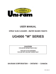
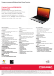
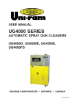
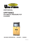
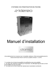
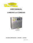
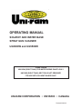
OPERATING MANUAL
SOLVENT AND WATER BASE
SPRAY GUN CLEANER
UG5000W and UG5500W
CAUTION
UM120W (RIGHT TANK) FOR WATER BORNE PAINTS ONLY
UM120W (RIGHT TANK) SECTION IS NOT DESIGNED
FOR USE WITH SOLVENT BASED PAINT
UNI-RAM CORPORATION • ONTARIO • CANADA
Revised 2009-03
MANUAL - SPRAY GUN CLEANERS - UG5000W and UG5500W
Revision 2009-05
CONTENTS
INTRODUCTION . . . . . . . . . . . . . . . . . . . . . . . . . . . . . . . . . . . . . . . . . . . . . . . . . . . . . . . . . . . . . . 3
FEATURES . . . . . . . . . . . . . . . . . . . . . . . . . . . . . . . . . . . . . . . . . . . . . . . . . . . . . . . . . . . . . . . . . . 3
SETUP
INSPECTION . . . . . . . . . . . . . . . . . . . . . . . . . . . . . . . . . . . . . . . . . . . . . . . . . . . . . . . . . . . . . . . . .
STRUCTURE . . . . . . . . . . . . . . . . . . . . . . . . . . . . . . . . . . . . . . . . . . . . . . . . . . . . . . . . . . . . . . . . .
LOCATION . . . . . . . . . . . . . . . . . . . . . . . . . . . . . . . . . . . . . . . . . . . . . . . . . . . . . . . . . . . . . . . . . . .
LEVELING, VENT AND AIR SUPPLY. . . . . . . . . . . . . . . . . . . . . . . . . . . . . . . . . . . . . . . .
SOLVENT SELECTION . . . . . . . . . . . . . . . . . . . . . . . . . . . . . . . . . . . . . . . . . . . . . . . . . .
PAIL SETUP . . . . . . . . . . . . . . . . . . . . . . . . . . . . . . . . . . . . . . . . . . . . . . . . . . . . . . . . . . .
3
4
5
5
5
5
OPERATION
LEFT TANK (UG4000 or UG4500), SOLVENT BASE . . . . . . . . . . . . . . . . . . . . . . . . . . .
PRE-CLEAN . . . . . . . . . . . . . . . . . . . . . . . . . . . . . . . . . . . . . . . . . . . . . . . . . . . . . . . . . . .
CLEANING SPRAY GUNS AND CUPS . . . . . . . . . . . . . . . . . . . . . . . . . . . . . . . . . . . . . .
USING THE FLOW-THROUGH BRUSH . . . . . . . . . . . . . . . . . . . . . . . . . . . . . . . . . . . . .
RIGHT TANK (UM120W), WATER BASE. . . . . . . . . . . . . . . . . . . . . . . . . . . . . . . . . . . . .
PREPARING SPRAY GUNS AND CUPS . . . . . . . . . . . . . . . . . . . . . . . . . . . . . . . . . . . . .
MANUALLY WASHING SPRAY GUNS OR PARTS . . . . . . . . . . . . . . . . . . . . . . . . . . . . .
TANK CLEANING . . . . . . . . . . . . . . . . . . . . . . . . . . . . . . . . . . . . . . . . . . . . . . . . . . . . . . .
AFTER CLEANING GUNS . . . . . . . . . . . . . . . . . . . . . . . . . . . . . . . . . . . . . . . . . . . . . . . .
HOSE CLEANING (UG5500W MODEL ONLY) . . . . . . . . . . . . . . . . . . . . . . . . . . . . . . . .
6
6
6
6
6
6
7
7
8
8
DAILY MAINTENANCE
FILTER PADS AND SCREEN. . . . . . . . . . . . . . . . . . . . . . . . . . . . . . . . . . . . . . . . . . . . . . 9
REPLACING SOLVENT (UG4000 or UG4500) . . . . . . . . . . . . . . . . . . . . . . . . . . . . . . . . 9
REPLACING WATER and CLOTH FILTERS (UM120W) . . . . . . . . . . . . . . . . . . . . . . . . . 9
TROUBLESHOOTING CHART . . . . . . . . . . . . . . . . . . . . . . . . . . . . . . . . . . . . . . . . . . . . . . . . 10-11
TROUBLESHOOTING PROCEDURES. . . . . . . . . . . . . . . . . . . . . . . . . . . . . . . . . . . . . . . . . . . . 12
FLOW DIAGRAM . . . . . . . . . . . . . . . . . . . . . . . . . . . . . . . . . . . . . . . . . . . . . . . . . . . . . . . . . . . . . 13
REPLACEMENT PARTS . . . . . . . . . . . . . . . . . . . . . . . . . . . . . . . . . . . . . . . . . . . . . . . . . . . . .14-15
ACCESSORIES, CONSUMABLES and OPTIONAL PARTS. . . . . . . . . . . . . . . . . . . . . . . . . . . . 16
WARRANTY
EXTENDED WARRANTIES For North American Customers. . . . . . . . . . . . . . . . . . . . . 16
FULL PRODUCT WARRANTY . . . . . . . . . . . . . . . . . . . . . . . . . . . . . . . . . . . . . . . . . . . . 17
2
MANUAL - SPRAY GUN CLEANERS - UG5000W and UG5500W
Revision 2009-05
INTRODUCTION
Uni-ram holds many patents on designs used in its innovative products. Every machine is tested
for compliance with Quality Assurance standards. Follow the directions in this manual under Setup,
Operation and Maintenance in order to operate this machine safely and effectively. Not following
these instruction can lead to malfunction or damage to the machine. Follow directions under the section below, Cautions and Warnings and on labels attached to the machine. Ensure that the manual
is readily available for the operator at all times. If you have any questions about the operation of this
machine, call your distributor or a Uni-Ram Service Engineer.
North America:
Uni-ram Technical Service
1-800-417- 9133
Other Continents:
Contact Your Supplier
FEATURES
This unit combines a Spray Gun Cleaner for solvent-based paints on one side (left) and a Spray Gun
Cleaner for water borne paints on the other (right). The left side is equivalent to either a UG4000 or a
UG4500 and the right side to a UM120W. The UG4500 is a UG4000 plus hose cleaning therefore the
UG5500W is equivalent to a UG4500 on the left side.
The left (solvent) side has automatic wash, automatic air flush, automatic solvent rinse, automatic
fume venting with on/off control, manual rinse with Flow-through Brush and a stainless steel tank and
lid. Two spray guns can be cleaned at the same time and the UG5500W can also clean hoses on the
left side. The UM120W side is used to manually clean and rinse one spray gun at a time. It also has a
stainless tank and lid.
The unit comes with a closed-top high density plastic pail for washing already installed on the left side
and and an open-top plastic pail with filters on the right side, also installed. The clean solvent pail for
rinsing is not included and must be supplied by the user.
SETUP
INSPECTION
•
•
•
Inspect the shipping carton for signs of damage. It is your responsibility to report damage to the
transport company. Uni-ram Corporation does not accept responsibility for shipping damage
once the machine has left our warehouse. Keep the packaging materials until you are sure the
machine has not been damaged during shipping.
Remove the machine from the carton by opening the bottom flaps and sliding the carton up over
the machine.
Make sure the bag of accessories contains the following:
• Manual
• Nozzle Adapters, 1 each of 3 kinds (Part Nos. 110-430,110-430SA, 110-430PC)
• Trigger Clamp and Plug Kit - 2 Pieces (Part No. 140-2340)
• Air Blow Gun (Part No. 102-7010)
• Wash Gun (Part No. 102-7020)
If any item is missing, contact your supplier.
3
MANUAL - SPRAY GUN CLEANERS - UG5000W and UG5500W
Revision 2009-05
STRUCTURE
CLEAN
RINSE
AIR RINSE
AUTO WASH
TIMER
VENT
VENT ON/OFF
CONTROL
COAGULATION
TIMER
BRUSH ON/
OFF & FLOW
CONTROL
AIR
BLOW
GUN &
WASH
GUN
WHIP LINE
GROUND
WIRE
WASH PAIL
- SOLVENT
SOLVENT RINSE
PAIL (NOT
SUPPLIED)
WASH PAIL WITH
FILTERS -WATER
BORNE
4
MANUAL - SPRAY GUN CLEANERS - UG5000W and UG5500W
Revision 2009-05
LOCATION
Position in a well-ventilated area away from sparks, heat and open flames.
LEVELING, VENT AND AIR SUPPLY
•
•
•
Level the machine using the adjustable legs.
Remove the cover on the "Air Input" (right side of machine) and attach an air supply adapter
(not supplied).
Replace the female quick connect on the Whip Air Line with a quick connect that will fit the male
quick connect of your spray gun (if necessary).
The air supply pressure must be at least 85 PSI and
the air must be free from contaminants such as water, dust, rust, tar, grease etc.
To prevent damage to the Diaphragm Pump an internal Air Pressure Regulator has been
installed to limit the air pressure to precisely 85 PSI. Do not install a second air pressure regulator or use a pressure set below 85 PSI.
CONNECT AIR BLOW GUN and WASH GUN WITH SPLASH GUARD
Remove the two Guns from the Accessories bag and connect the blue hoses to the appropriate connector on the right side of the unit, using the labels as a guide. To install the brackets for the two
Guns, remove the brackets from inside the right-hand tank and attach them to the outside of the Tank
using the same screws.
SOLVENT SELECTION
The adhesion quality of automotive paint has dramatically improved in recent years. The choice of
solvent is critical. Only use good quality solvent that is formulated for your paint and intended for use
with automatic spray guns cleaners.
PAIL SETUP
•
•
•
Open the door to the base cabinet
One 5-Gal (19 L) white plastic round top closed pail is provided for the left tank and one open
top pail with a filter for the right tank. A full pail of clean solvent is required (not supplied).
The Suction Pipe is already inserted in the white wash pail. If necessary, open the Drain Valve
under the left tank (vertical position) and fill this pail 2/3 full (3 Gal) by pouring solvent into the
tank and letting it drain into the pail. Insert the Rinse Pump and manual wash tube into a pail of
clean solvent (not supplied) and place the pail inside the cabinet.
5
MANUAL - SPRAY GUN CLEANERS - UG5000W and UG5500W
Revision 2009-05
OPERATION
LEFT TANK (UG4000, SOLVENT BASE)
PRE - CLEAN
•
Disconnect the spray gun from the air hose. Pour paint from the cup (when present) into a 5
gallon pail (not supplied).
•
Rinse cup with solvent and pour into the same 5 gallon pail for later disposal or recycling.
CLEANING SPRAY GUNS AND CUPS
•
•
•
•
•
•
•
Loosen the air cap of the spray gun two full turns.
Lock the trigger in the open position with the Trigger Lock Spring.
Plug air inlet of spray gun with cap to prevent solvent from entering passage. Caps are supplied
in the accessory kit.
Place spray guns facing corner jets. Placement depends on type of spray gun. See pictures
below. Place cups onto the low spray jets and cup holders.
Close the lid and turn the “Auto Wash Timer” knob clockwise to start cleaning. The cleaning
cycle takes about 60 seconds
Push and hold the "Air Rinse" button for about 3 second to air-rinse the guns.
Push and hold the "Clean Rinse" button for about 5 seconds to rinse guns with clean
solvent. This will send a pre-set amount of clean solvent (100 cc) through the jets. Wait 30 seconds for the Rinse Pump to fully recharge before repeating.
The solvent flow per clean-rinse cycle is limited to 100 cc to minimize consumption. This quantity is usually sufficient to clean the inside pasages of the spray guns.
USING THE FLOW-THROUGH BRUSH
•
To deliver clean solvent through the Brush for rinsing, step on the foot pedal.
Solvent flow through the rinse brush is limited to minimize clean solvent consumption.
RIGHT TANK (UM120W, WATER BASE)
This tank is used to clean spray guns, cups and parts. There are two modes of operation - Manual
Wash and Manual Rinse.
PREPARING SPRAY GUNS AND CUPS
•
Disconnect the spray gun from the air hose. Empty the paint cup in to the wash tank
•
•
•
•
Rinse the cup with water and pour the water in to the wash tank for later filtering.
Loosen the air cap of the spray gun two full turns.
Lock the trigger in the open position with the Trigger Lock Spring.
Plug air inlet of spray gun with cap to prevent water from entering passage. Caps are supplied
in the accessory kit.
Connect the Manual Cleaning Hose to the Spray Gun
•
6
MANUAL - SPRAY GUN CLEANERS - UG5000W and UG5500W
Revision 2009-05
NOTE: THE PICTURES ABOVE APPLY ONLY TO THE SOLVENT SIDE (LEFT TANK).
MANUALLY WASHING SPRAY GUNS OR PARTS
There are two ways to clean manually. One way is with the WASH GUN and the other is with
the FLOW-THROUGH BRUSH. The Gun and Brush share recirculated water from the WASH
PAIL. When using the Gun, water flow to the Brush must be turned off.
To use the Gun follow these steps:
1. Make sure the BRUSH ON/OFF & FLOW CONTROL lever is set to the CLOSE position
horizontal).
2. Step on the Foot Pedal (right side)
3. Squeeze the trigger.
To use the Brush follow these steps:
1. Make sure the BRUSH ON/OFF & FLOW CONTROL lever is set to the OPEN position
(vertical).
2. Step on the Foot Pedal (right side)
3. To adjust the flow of water through the Brush, turn the lever back slightly until the desired
flow is achieved.
7
MANUAL - SPRAY GUN CLEANERS - UG5000W and UG5500W
Revision 2009-05
TANK CLEANING
•
•
•
•
Tank is filled with dirty water and there is no water left in the wash pail.
Lift the wash screen and add the floculent and put the screen back and closed the lid.
Turn the coagulation timer. Air will agitate the water and floculent. Let the mixture settled for 5 minutes.
Open the drain Valve. Let the Water drain through the filter into 19L pail. The filter will collect the
paint debris. If further cleaning the wash tank is required, use fresh water to fluch out the tank.
AFTER CLEANING GUNS
•
•
•
•
Remove the guns and cups from the tank and wipe them dry. Do not store spray guns in the tank.
Close the drain valve of the water base gun cleaner tank( right sidt).
Check the cloth filter of the water base gun cleaner and replace it if neccessary.
Chech the condition of the filtered water. It can be reused. If neccessary drain the filtered water as
per law and filled the wash pail with fresh water.
HOSE CLEANING (UG5500W MODEL ONLY)
• Models with this feature can be used to clean a paint feeder hose up to 100 feet
(30 m) long. Connect the hose to the two fittings on the left side (Solvent Outlet
SOLVENT RETURN
SOLVENT OUTLET
MODE SELECTOR
8
MANUAL - SPRAY GUN CLEANERS - UG5000W and UG5500W
•
•
•
Revision 2009-05
and Solvent Return). Rotate the "Mode Selector" handle to the horizontal position
and turn the Timer knob clockwise to start the automatic cleaning cycle.
To air-rinse the hose, push and hold the "Air Rinse” button.
To rinse the hose with clean solvent, push and hold the "Clean Rinse" button for
about 5 seconds. This will use about 100 cc of clean solvent. Wait 30 seconds for
the Rinse Pump to fully recharge before repeating.
Disconnect the hose.
DAILY MAINTENANCE
FILTER PADS AND SCREEN
•
•
•
Inspect the filter pad in the Left Tank (UG4000) and clean it if there is a build up of paint debris.
Clean by removing the filter pad and washing away paint particles with clean solvent. Replace the
filter pad when damaged or when solvent cannot drain.
Inspect the Work Screen in the Left Tank (UG4000), under the filter pad and clean when necessary.
Inspect the Water Base filters in the pail under the right-hand tank. Make sure the tank and work
screen are clean and free from paint debris. Replace the filters if neccessary.
REPLACING SOLVENT (UG4000 or UG4500)
•
•
•
•
•
Disconnect the Suction Pipe from the Drain Valve and remove the pipe from the pail. Move the pail
out of the cabinet and recycle or dispose of the wash solvent.
Remove the Rinse Pump from the other pail, move the pail out of the cabinet and locate on left
side for use with the suction pipe.
.
Place a new, full-pail of clean solvent on the right side in front of the cabinet.
Insert the Rinse Pump into the full pail on the right and the Suction Pipe into the half-full pail on
the left. Models with a Manual Wash brush also have a tube to supply the brush. The tube must be
inserted through the lid of the left (wash) pail. Models with a Manual Rinse feature have another
tube which needs to be inserted through the lid of the right (rinse) pail.
Move the pails into the cabinet and re-connect the Suction Pipe of the left pail to the Drain Valve.
REPLACING WATER AND CLOTH FILTERS (UM120W)
•
•
Move the pail out of the cabinet. Remove the suction tube and filters from the pail and dispose of
the cloth filters. Empty out the filtered water. Fill with fresh water
Place new filters into the fliter unit. Place the Filter unit and suction tubes into the pails and place
them back into the cabinet and close the door.
9
MANUAL - SPRAY GUN CLEANERS - UG5000W and UG5500W
Revision 2009-05
TROUBLESHOOTING CHART
SYMPTOM
WASH SOLVENT OR
WATER DOES NOT FLOW
AND PUMP MAKES A
NORMAL PUMPING SOUND
REASON
• Drain valve closed
• Solvent or water level too
low
• Paint debris in pump
• Blockage in solvent line
WASH SOLVENT OR
WATER DOES NOT FLOW
AND PUMP MAKES A
HISSING SOUND
WASH SOLVENT OR
WATER DOES NOT FLOW
AND PUMP DOES NOT
MAKE A SOUND
CORRECTIVE ACTION
After each step, turn the Timer
Knob (Solvent) or press the
Foot Pedal (Water). If liquid
does not flow, carry out the
next step.
• Open drain valve (UG4000)
(vertical position).
• Check wash solvent level. Add
solvent if less than 1/2 full.
• Follow Procedure 1, Blocked
Fluid Passage in Diaphragm
Pump.
• Follow Procedure 4, Blocked
Passage in Solvent Line
• Water in air line causes
pump to stall
• Follow Procedure 2, Blockage
in Air Passage in Diaphragm
Pump
• Pump leaks
• Replace pump
• Blockage in air passage
• Follow Procedure 3, Blocked
Passage in Air Line
PUMP DOES NOT STOP
UNLESS TIMER IS TURNED • Defective timer (UG4000)
BY HAND OR AIR IS SHUT • Air Valve stuck (Water
OFF OR WHEN FOOT
Base)
REMOVED FROM PEDAL
(WATER BASE)
• Replace timer
• Replace Air Valve
TIMER KNOB SPINS BACK • Defective timer
WHEN TURNED
• Replace timer
• Solvent lacks cleaning
INSIDE WALL OF TANK
strength
IS COATED WITH PAINT
EVEN THOUGH OPERATOR
MAINTAINS TANK
• Replace solvent with solvent
that is formulated for type of
paint used and for use with
automatic spray gun cleaning
10
MANUAL - SPRAY GUN CLEANERS - UG5000W and UG5500W
Revision 2009-05
TROUBLESHOOTING CHART
SYMPTOM
REASON
CORRECTIVE ACTION
CLEANING PROBLEMS
GUNS NOT CLEAN,
PUMP WORKING,
SOLVENT OR WATER
FLOW NORMAL
GUNS NOT CLEAN,
WASH SOLVENT IS
MILKY WHITE
After Each Step Below, Turn Timer. If
guns are not clean, carry out next step.
• Trigger not locked in • Use Trigger Lock Spring
open position
• Spray gun is not
• Re-install with proper adapter
properly installed on
to nozzle
• Incompatible solvent • Replace incompatible solvent with solvent formulated for type of paint used
• Water too
and for Automatic Spray Gun Cleaners.
dirty(UM120W)
• Low pressure in air
supply
• Increase air pressure to a minimum of
85 PSI
• Plugged jets
• Remove and clean by blowing air
through the jets. If not successful,
replace.
• Wash solvent is con- • Replace or recycle wash solvent
taminated with water
CLEAN RINSE DOES NOT • Not enough solvent in • See Section “REPLACING SOLVENT”
clean rinse pail (right
WORK
side)
• Rinse Pump is leak- • Replace rinse pump
ing from a crack
caused by corrosion
due to acidic or chlorine-contaminated
solvent
• Clean Rinse Air Valve • Follow Procedure 3, “Blocked Passage
is defective
in Air Line” for air rinse valve only.
CLEAN RINSE IS DIRTY
• Faulty Combination
Valve
11
• Replace Combination Valve.
MANUAL - SPRAY GUN CLEANERS - UG5000W and UG5500W
Revision 2009-05
TROUBLESHOOTING PROCEDURES
PROCEDURE 1
Blocked Fluid Passage In Diaphagm Pump
If the pump sounds like it is working but liquid does not flow, clear
the fluid passage as follows:
• Remove suction tube from the pail and blow air at 85 PSI
into the INLET Sovent Hose (see diagram). Step on foot
pedal. This procedure may have to be repeated several
times. If this procedure does not help, blow some water into
the suction hose using a spray gun, wait one minute and
step on foot pedal. This procedure may have to be repeated
several times. If this procedure does not work, the pump
must be replaced.
If you need to replace the pump call your local dealer. The warranty on the diaphragm pump is two years from date of purchase.
This procedure will also clear a blockage in the fluid line for
the wash gun.
PROCEDURE 2
Blocked Air Passage In Diaphragm Pump
If there is a steady hissing sound and the pump is not cycling, the
spool valve has stalled due to a blocked air passage. Follow the
procedure below to clear the blockage.
•
•
•
Connect a blow gun to an 85 PSI source. Locate the blue
hose that extends from the air exhaust port of the diaphragm
pump. Use a blow gun to blow air into the open end of this
hose. Turn timer. If the procedure is successful, the pump will
start working. The procedure may have to be repeated several times. If this procedure does not work, replace the pump.
Cause: Contaminants in the air supply (water, oil, solid particles etc)
Preventative Action: If necessary, install an Airline (Moisture) Filter.
PROCEDURE 3
Blocked Passage in Air Line
The components in the air line are the diaphragm pump, air valve, foot pedal, 3-way ball valve
and regulator. See the Flow Diagram and the section: Replacement Parts.
To troubleshoot a component:
1) Disconnect the air line to the component using the quick disconnect.
2) Step on foot pedal and check for presence of positive air pressure in the air line. If there is ample
positive air pressure, replace the component.
If air pressure is absent, there is a faulty component upstream. Reconnect the air line and check the
operation of the next component upstream by following steps 1 and 2 above.
12
MANUAL - SPRAY GUN CLEANERS - UG5000W and UG5500W
FLOW DIAGRAM
Shows the flow of solvent and compressed air.
13
Revision 2009-05
MANUAL - SPRAY GUN CLEANERS - UG5000W and UG5500W
Revision 2009-05
REPLACEMENT PARTS
DESCRIPTION
Part Number
FLOW-THROUGH BRUSH
144-390
DIAPHRAGM PUMPUDP4TA
UDP4TA
AIR BLOW GUN
102-7010
TIMER KIT
115-200/K
VALVES (PEDAL,RINSE ETC)
115-400BF
NOZZLE EXTENSION, REGULAR
110-430
NOZZLE EXTENSION, SATA
110-430SA
TRIGGER CLAMP & PLUG KIT
140-2340
LID SWITCH
115-350F
WASH PAIL
780-811P
RINSE PAIL
780-8111P
PAIL, WATERBORNE (OPEN TOP)
102-8111P
GROUND WIRE
600-8901
WHIP LINE
102-3980
SOLVENT (LEFT) TANK
120-318, HANDLE
144-390, FLOW-THROUGH
BRUSH ASSY (INSIDE)
140-361F, DELIVERY TUBE ASSY
WITHOUT JETS
140-332N, FLAME
RETARDANT SCREEN
110-356, TAPER NOZZLE
100-350, SPRAY JETS
110-351, DELIVERY TUBE
PLATE HOLDER
FP6500-1, FILTER PAD
140-450, DELIVERY TUBE
CONNECTOR ASSY
10-171, TANK DRAIN
VALVE
120-020PR, AIR INLET
WITH PRESSURE
REGULATOR (NOT
SHOWN)
140-400F, COMBINATION
VALVE (NOT SHOWN)
140-421F, QC NIPPLE
140-450, DELIVERY TUBE
CENTER CONNECTOR ASSY
14
MANUAL - SPRAY GUN CLEANERS - UG5000W and UG5500W
Revision 2009-05
REPLACEMENT PARTS - UM120W
Filters
Primary, 400 Micron, 102-8125
Secondary, 25 Micron, 102-8126
Filter Holder, 102-8120
Wash Pail,19L, 102-8111P
Work Screen, 102-3030
Air Agitator, 102-3580
Drain Hole (Shut Off
Valve underneath,
not shown)
AIR AGITATION SYSTEM
Note: For additional replacement parts, see the list of included parts on page 3.
15
MANUAL - SPRAY GUN CLEANERS - UG5000W and UG5500W
Revision 2009-05
ACCESSORIES, CONSUMABLES and OPTIONAL PARTS
Part
No.
110-430
110-430MJ
110-430MJP
110-430L1
110-430L1P
100-413F
115-200/K
102-8124
140-340S
144-390
144-397
100-835
600-8901
10-220
FP6500-10
Description
Nozzle Adapter, All models, Push On
Nozzle Adapter, SATA, Mini Jet, Threaded
Nozzle Adapter, SATA, Mini Jet, Push On
Nozzle Adapter, Threaded, SATA - 0.6 & 1.0 litre cups
Nozzle Adapter, Push-On, SATA - 0.6 & 1.0 litre cups
Paint Cap Holder
Mechanical Timer Assembly, 5 minutes
Filter Bag.
Rotating Spray Jet Assembly
Flow-Through Brush Assembly
Hose for Flow-Through Brush
Ground Wire for Gun Cleaner, 18G, Green, 4 FT
Ground Wire for Pail
Airline (Moisture) Filter (Optional)
Filter Pad, Regular, 13.75” x 17.5", Pkg of 10
EXTENDED WARRANTIES For North American Customers
An extended warranty may be purchased within 3 months from the date of purchase.
There are two types of warranty:
1) parts
2) parts and labour
The warranty period is 2, 3 or 4 years.
If you would like to purchase an extended warranty call Uni-ram at:
Canada
1-800-417-9133
USA
1-800-735-4331
16
MANUAL - SPRAY GUN CLEANERS - UG5000W and UG5500W
Revision 2009-05
Full Product Warranty
These Uni-ram products have been engineered and manufactured to high performance standards.
Each unit has been subjected to detailed factory testing before shipment.
This product comes with a one-year full warranty from the date of purchase. Uni-ram Corporation
reserves the right to repair or replace the unit, free of charge, to the original purchaser if a part is
found to be defective in material or workmanship as determined by factory service personnel. The
items listed below under "Conditions of Warranty" as consumables are not covered.
Uni-ram reserves the right to direct the customer to ship the unit collect to the Uni-ram factory or to
an approved Service Center for repair using the Uni-ram Return Goods Procedure or to repair the
unit on-site. To prevent damage in transport, the purchaser must ship the unit in the original packaging or use alternate adequate packaging. All units must be shipped clean and free of solvent.
Diaphragm Pump:
We are pleased to advise that the warranty on the diaphragm pump, the heart of the spray gun
cleaner, comes with a 2 year replacement warranty. If, in the unlikely event your diaphragm pump
fails during the first two years of service, call Uni-ram Service at 1-800-417-9133. We will send you
a new pump free of charge and arrange for the return of your original pump.
Conditions of Warranty:
As Uni-ram Corporation has no control over the working conditions or circumstances under which
the purchaser stores, handles or uses the product, Uni-ram makes no warranty or claim, either
expressed or implied with respect to this product's fitness for any purpose or the result to be
obtained from its use. This condition applies to the sale of all products and no representative or distributor of Uni-ram Corporation has the authority to waive or change these conditions.
This warranty applies only to the original purchaser and does not apply if the unit has been misused, overloaded, neglected, altered or used for any purpose other than those specified in the
operating and installation instructions. Deterioration due to normal wear is not covered by this
warranty. Damage due to accident, transportation, fire, floods or acts of God is also not covered.
Units whose serial numbers have been altered or removed are not covered. The warranty is invalid
if unauthorized chemicals as noted in the manual or solvents with acid content are used in this
unit. Unauthorized attempts at self-repair or alterations by the owner also invalidate this warranty.
Interior or exterior finishes are not covered by this warranty.
Consumable Items are not covered by this warranty (eg: gaskets, screens, bags, filters, nozzles
and air jets).
This warranty replaces all other warranties expressed or implied by statute or otherwise.
To make a claim, call Uni-ram Service at 1-800-417-9133 and quote the serial number of the
unit.
17