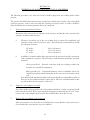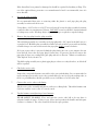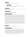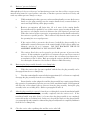
1
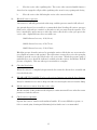
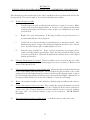
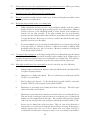
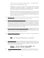
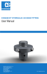
Serial Number ___________________
Part Number ____________________
COSASCO® MODEL RSL
RETRIEVER AND SERVICE VALVE
USER MANUAL
ROHRBACK COSASCO SYSTEMS, INC.
11841 E. Smith Avenue
Santa Fe Springs, CA 90670
Phone: (1) 562-949-0123
Fax: (1) 562-949-3065
E-mail: [email protected]
Web Site: http://www.rohrbackcosasco.com
600006-MANUAL REV. -
i
TABLE OF CONTENTS
Section
Contents
Page
1.0
INTRODUCTION
1
2.0
SAFETY CHECKLIST
3
3.0
RETRIEVER & SERVICE VALVE
CONSTRUCTION & OPERATION
5
4.0
RETRIEVAL OF SOLID OR
HOLLOW PLUG ASSEMBLIES
7
5.0
INSTALLATION OF SOLID OR HOLLOW PLUG
ASSEMBLIES UNDER PRESSURE
13
6.0
RETRIEVER BACK PRESSURING
17
7.0
RETRIEVER & SERVICE VALVE SPECIAL TOOLS
19
8.0
RETRIEVER MAINTENANCE
25
9.0
3600 PSI SERVICE VALVE MAINTENANCE
31
10.0
6000 PSI SERVICE VALVE MAINTENANCE
37
ii
iii
SECTION 1.0
INTRODUCTION
The Rohrback Cosasco Systems RSL Retriever is the newest innovation from the leader in
high pressure access equipment. This precision tool allows safe, easy insertion and
removal of various equipment and tools through the industry-standard Rohrback Cosasco
Systems Access Fitting – while the pipeline or vessel is under pressure. Used in
conjunction with the Rohrback Cosasco Systems Service Valve, system pressure is safely
ported into the tool which allows the valve to be opened and the retrieval operation to be
performed. Rotation and translation in and out of the fitting is
controlled by two adjustable handles.
No movement or
telescoping of the tool body is necessary and best of all, no
hydraulic pumps or hoses are required. This tool can be used with
the industry-standard Rohrback Cosasco Systems access fitting
and service valves, with no adapters required.
Each RSL Retriever Kit is furnished with service tools and spare
parts in a sturdy field service box to provide compact, easy storage
and portability.
The new COSASCO® RSL 2500 and 6000 Retrievers utilize a compact non-telescoping
design that provides the highest level of safety and the advantage of a short tool length
without the inconvenience of hydraulic pumps and fluid. Best of all, it is compatible with all
COSASCO® 2” High Pressure Access fittings without the need for special adapters.
Access under pressure for Bottom-of-the-Line monitoring locations requires minimal
clearance, avoiding the need to produce access pits or to raise the pipe work. The design
without the use of sliding seals provides for easy tool maintenance and cleaning. The
elimination of sliding seals reduces the cost of seal replacement.
1
2
SECTION 2.0
SAFETY CHECKLIST
1.
Safe operation requires a minimum of 2 trained operators.
2.
Do not use this retrieval equipment unless you have been trained in its safe operation.
3.
If it has been longer than 90 days since your last operation, you should review the manual and
first practice on a dummy fitting prior to use.
4.
Make sure you have complied with all plant safety requirements and environmental
regulations.
5.
Identify the type media its pressure and temperature. Review material safety data information
on the media prior to operation.
6.
Insure you have all the required safety equipment for the given media, "i.e. hard hat, safety
glasses, protective clothing, safety gloves, respirator, spill safety equipment, etc...
7.
Any actions which could vary system pressure such as surges caused by opening and closing of
valves and chokes should be delayed until completion of retrieval operations.
8.
Insure you have enough clearance for safe operation. Note wind direction prior to starting
operations involving hazardous products.
3
4
SECTION 3.0
RETRIEVER & SERVICE VALVE CONSTRUCTION & OPERATION
RSL-2500 retrievers feature a stainless steel outer barrel, Viton o-rings, and graphite-impregnated
Teflon dynamic seals. They are pressure rated to 2500 psi (172 BAR) and have a maximum operating
temperature of +400BF (+204BC).
RSL-6000 retrievers feature a stainless steel outer barrel, Viton o-rings, and graphite-impregnated
Teflon dynamic seals. They are pressure rated to 6000 psi (414 BAR) and have a maximum operating
temperature of +400BF (+204BC).
On both models, a socket adapter assembly attached to the carrier assembly is used to install or
retrieve the plug from the access fitting assembly. The hammer nut on the outer barrel of the retriever
connects directly to the outlet side of the service valves.
Two valves are available. The standard valve is rated at 3600 psi (248 BAR) and the high pressure
valve is rated at 6000 psi (413 BAR). Both valves have a maximum operating temperature of 250BF.
Their selection depends on the maximum working pressure required. The service valves incorporate
two needle valves; the first allows slow pressurizing of the retriever, which reduces the torque required
to open the service valve ball. The second allows product bleed-off through a special port, either with
or without the optional diverter hose assembly. The valves comply with API Fire-Safe Standard RP6F.
When the fittings are mounted at bottom-of-line they collect sand, scale or other debris. These
particles can damage the threads of the access fittings, as well as the working surfaces of the retriever
and service valve. Therefore, extra care and maintenance should be given to equipment used in
servicing any bottom-mounted fitting. Special tools are available to aid in these situations. (See
Section 7 - Retriever and Service Valve Special Tools, which describe the tools available to remove or
flush sand, scale, hot tap chips or other debris from the access fitting.)
If product and operating pressure permit (lower than 2500 PSI, 172 BAR), the RSL-2500 retriever
with its thinner stainless steel outer barrel should be considered to reduce the weight.
The retriever has eight main parts (see figure 1):
1.
2.
3.
4.
5.
6.
7.
8.
Outer Barrel.
Rotation Tube.
Translation Tube.
Socket Adapter Carrier.
Socket Adapter Assembly.
Head Assembly.
Hammer Nut Assembly.
Bleed Valve Assembly.
5
Figure 1
6
The socket adapter carrier is moved in translation and rotation by rotating the two handles on the head
assembly. Rotating the outermost handle clockwise moves the carrier into the access fitting or rotating
it counterclockwise moves the carrier into the retriever. Rotating the larger, inner handle clockwise
rotates the carrier in the same direction as the handle.
The service valve has three main parts.
1.
2.
3.
The service valve body.
The ball and seals.
The bypass and bleed valve.
The COSASCO access fitting body and plug assembly (hollow or solid) form a seal. However, the
design allows the system pressure to bypass the seal when the plug assembly is "backed off" one or two
turns. The bypass pressure enters the retriever through the service valve.
A “normal” retrieval operation consists of the following steps. Each step will be covered in further
detail in section 4.
1. Prepare the access fitting. This involves verifying the system parameters; pressure, temperature,
process fluid, system surges, etc. The area must be checked for adequate clearances, safety, other
personnel, etc. The protective cover and pipe plug are removed from the fitting, and the plug is
loosened slightly, or “cracked”. The retriever and service valve should be checked to assure smooth
operation, and proper assembly.
2. Install the service valve onto the access fitting. Insure that the valve is fully open, and the bleed and
bypass valves are closed.
3. Install the retriever onto the service valve. Insure that the bleed valve on the retriever is closed.
4. Use the retriever to retrieve the plug assembly. The general steps are as follows:
a. Rotate the translation handle clockwise to move the socket adapter to the top of the plug.
b. Rotate the rotation handle clockwise to thread the socket adapter into the plug
assembly. Slight clockwise pressure should be maintained on the translation handle to
move the carrier forward as the thread engages the plug assembly, but not so much
pressure that the hex on the socket adapter drops over the plug assembly. Thread the
socket adapter into the plug assembly about 4 or 5 turns.
c. Rotate the translation handle clockwise to drop the hex over the plug assembly. The
rotation handle will need to be turned slightly during this operation in order to line up the
hex with the plug. You will know when it is aligned and dropped onto the plug when the
translation handle can advance about 90°. Also, the rotation handle will be difficult to turn
when the hex is dropped over the fitting.
d. While maintaining slight clockwise pressure on the translation handle (to assure the
socket adapter hex stays dropped over the plug assembly), rotate the rotation handle
counterclockwise slowly. System pressure should enter the retriever (as seen on the
pressure gage on the bleed valve assembly) after 1 to 2 turns. Once pressure is stabilized,
7
continue to turn the rotation handle counter clockwise to completely remove the plug from
the fitting. This normally takes about 14 rotations, and you will often hear and/or feel a
‘click’ sound once each rotation once the plug is out of the fitting.
e. Rotate the translation handle counterclockwise to pull the plug assembly into the
retriever tool. If the translation handle only rotates about 90° and then stops, then the plug
assembly is not fully unthreaded from the access fitting. Return to step ‘d.’ and continue to
unthread the plug. If it rotates freely, then the plug is unthreaded and you will continue
rotating counterclockwise until it stops when the socket adapter carrier has reached the top
of the retrieval tool.
f. Slowly close the service valve, making sure there is no obstruction in the valve. Once
fully closed, bleed off pressure from the retrieval tool, using either the bleed valve on the
retriever or the service valve, or both. Verify pressure has been completely bled using the
pressure gage on the retrieval tool.
g. Remove the retriever from the service valve. Once removed, you can rotate the
translation handle clockwise to move the plug assembly out of the front of the tool for
removal.
5. To install a new device into the system, the following general steps are used. These steps will
be covered in greater detail in section 5.
a. Insure that the service valve is installed on the fitting, and that the valve, as well as the
bleed and bypass valves are closed.
b. Install the new device onto the socket adapter assembly, at least 4 to 5 turns. Rotate the
translation counterclockwise until it stops to fully retract the new device into the retriever
tool.
c. Install the retriever onto the service valve. Insure that the bleed valve on the retriever is
closed.
d. Slowly open the bypass valve on the service valve. Verify full system pressure on the
pressure gage on the retriever.
e. Slowly open the service valve. Insure the valve is open completely.
f. Rotate the translation handle clockwise until it stops. While maintaining clockwise
pressure on the translation handle, rotate the rotation handle clockwise to thread the plug
assembly into the access fitting body. Maintain clockwise pressure on the translation
handle to insure that the socket adapter hex remains over the plug assembly. The plug
assembly requires approximately 14 turns to fully seat into the access fitting body.
g. Rotate the translation handle counterclockwise to back the hex off of the access fitting
body. The translation handle should move about 90° counterclockwise. Rotate the
rotation handle counterclockwise a minimum of 5 turns to unthread the socket adapter
assembly from the plug assembly. If the hex is properly backed off of the plug assembly,
the rotation handle will rotate fairly easily. If it is difficult to rotate, then make sure the
8
translation handle is rotated counterclockwise as far as it will go.
h. Rotate the translation handle counterclockwise to move the socket adapter away from
the plug assembly. Bleed the pressure from the tool using the bleed valve on the retriever,
the bleed valve on the service valve, or both. Insure that the pressure is reduced to zero on
the pressure gage on the retriever.
i. The retriever and service valve may now be removed from the access fitting. Replace
the pipe plug and protective cover on the access fitting body.
9
10
SECTION 4.0
RETRIEVAL OF SOLID OR HOLLOW PLUG ASSEMBLIES
The following procedure is for retrieval of solid or hollow plugs from access fitting bodies under
pressure.
The operator should first determine pressure, temperature, and the type of media. Any action which
could vary pressure, such as surges caused by the opening or closing of valves or chokes, should be
delayed until after the retrieving operation has been completed.
1.
Stroke and circumferential clearance.
Determine if the retriever has an adequate stroke clearance and that the entire operation has
adequate circumferential clearance.
a.
Clearance beyond the top of the access fitting body is required for installation and
operation of the retriever and service valve. The following recommendations should
give adequate clearance:
18" stroke
25" stroke
37" stroke
b.
-
4 feet (1.2 meters)
5 feet (1.5 meters)
6 feet (1.8 meters)
In addition, circumferential to allow movement of the operator(s) and free movement
of the equipment is required. The following recommendations should give adequate
clearance:
Above ground level - From the center-line of the access fitting, a radius of at
least three feet should be maintained.
Below ground level - A minimum diameter culvert of manhole of four feet
should be provided; with the fitting placed off-center one foot from the culvert
wall.
Note that both the translation handles and rotation handles are adjustable in radius to
allow use in close radial proximity to other objects. However, using the handles in this
way will result in slower operation of the tool.
2.
Adjust the socket adapter assembly.
For solid or hollow plug assemblies, the socket adapter should be set in the second and fourth
holes from the hex end. When retrieving the hot tap plug assembly with the 14" or 18" stroke
retriever, the socket adapter must be in the first and third holes from the hex end.
3.
Remove the access fitting cover, if present.
After removing the cover, check the access fitting body to ensure that the o-ring contact area is
clean and that the acme thread is in good condition.
11
If the thread has been painted or damaged, it should be repaired by brushing or filing. The
use of the optional heavy protective cover manufactured of steel is recommended, since it is
more durable.
4.
Loosen the plug assembly.
It is recommended that, prior to removing either the plastic or steel pipe plug, the plug
assembly be unfrozen from its seat.
Using either a 1-1/8" socket or a 1-1/8” box-end wrench, loosen the plug assembly by turning
counterclockwise to a maximum of 1/4 turn. DO NOT loosen beyond the 1/4 turn maximum
or leakage may result. If leakage begins, tighten the plug as required to stop the leakage.
5.
Remove the pipe plug from the plug assembly.
The solid plug assembly uses a stainless steel pipe plug with a 1/2" square head which acts as a
secondary seal. Hold the plug assembly hex with a box-end wrench to prevent it from backing
off while using a crescent wrench to turn the pipe plug slightly counterclockwise.
If, for any reason, there is pressure behind the plug which, after one or two minutes, has not
been bled-off, loosen the steel pipe plug 1/8 turn more. If pressure bleeds-off, remove the
pipe plug; if it has not, re-tighten the pipe plug and refer to Section 7 -Retriever and Service
Valve Special Tools, Section 7.4.
The hollow plug assembly uses a plastic pipe plug as a dust cover only; therefore, no bleed-off
will be required.
6.
Check the service valve.
Inspect the o-ring at the hammer nut end for nicks, cuts and abrading. It is recommended to
inspect and pressure test the service valve periodically to be sure it is in good working order, as
there is a possibility that, should a problem occur, it will have to be left on the line.
7.
Connect the service valve to the fitting.
Lift the service valve assembly and place it on the access fitting body. Thread the hammer nut
clockwise until the service valve is securely seated.
8.
Tap the hammer nut tight using a brass hammer.
WEAR SAFETY GLASSES! Close and open the service valve ball to be sure there is
adequate handle clearance. If there is not, loosen and reposition the handle until adequate
clearance is obtained. The valve should be left in the open position.
12
9.
Check the retriever.
Inspect the thread adapter o-ring for nicks, cuts and abrading.
a.
Operate the retriever.
Operate the translation handle and rotation handles, and check that they operate
smoothly, without binding or excessive noise.
10.
To connect retriever.
Lift the retriever and place it on the service valve. Turn the hammer nut clockwise until the
retriever is seated on the service valve.
11.
Tap the hammer nut tight.
Using a brass hammer - WEAR SAFETY GLASSES!
12.
Connect the socket adapter pilot.
Rotate the translation handle clockwise to move the socket adapter to the top of the plug.
Once at the top of the plug, rotate the rotation handle clockwise to thread the socket adapter
into the plug assembly. Slight clockwise pressure should be maintained on the translation
handle to move the carrier forward as the thread engages the plug assembly, but not so much
pressure that the hex on the socket adapter drops over the plug assembly. This operation is a
little tricky at first, but is fairly simple once the concept is understood and practiced a few
times. While rotating the rotation handle, maintain enough clockwise pressure on the
translation handle to allow the pilot adapter to thread into the top of the plug assembly, but not
so much pressure that the hex socket drops over the plug assembly. If the rotation handle
becomes difficult to turn, rotate the translation handle slightly clockwise. If the rotation handle
becomes easy to turn, then continue threading it into the plug. If it remains difficult, then the
hex has probably engaged the plug, at which point you must rotate the translation handle
counterclockwise to disengage the hex, and then continue clockwise with the rotation handle.
Once properly engaged to the plug, thread the socket adapter into the plug assembly about 4
or 5 turns.
13.
Close bleed valves.
Ensure that both the retriever and service bleed valves are closed.
14.
Connect the socket adapter hex.
Rotate the translation handle clockwise to drop the hex over the plug assembly. The
rotation handle will need to be turned slightly during this operation in order to line up the
hex with the plug. You will know when it is aligned and dropped onto the plug when the
translation handle can advance about 90°. Also, the rotation handle will be difficult to turn
when the hex is dropped over the fitting. You may need to rotate the rotation handle in
either a clockwise or counter clockwise direction, while maintaining clockwise pressure on
the translation handle, until you feel the hex drop onto the plug assembly. This is the one
other operation which can be easily mastered with a few practice sessions.
13
15.
Retriever "pressure balancing".
Although this tool does not ‘telescope’ and introducing pressure into the tool does not present any
unusual safety hazard, it is good practice, and safest, to introduce pressure into the tool slowly, and
avoid any sudden pressure changes or surges.
16.
a.
While maintaining clockwise pressure on the translation handle, to assure the hex stays
firmly over the plug assembly, turn the rotation handle slowly counterclockwise, to
unseat and begin backing off the plug assembly.
b.
Retriever pressurization will begin after 1/2 to 2 turns of the rotation handle.
Pressurization will be signified by one of three means; gauge, hearing the fluid enter
the retriever, or feeling the increase in friction as the seals experience pressure load.
When the retriever begins to pressurize, stop turning the rotation handle and wait for
the retriever to equalize pressure. This is achieved only when the entire retriever and
the operating line are at equal pressure.
c.
If the retriever fails to pressurize after 2 turns, back-off the plug assembly by an
additional 2 counterclockwise turns of the rotation handle. If the retriever still has not
balanced, wait for 10 to 15 minutes. DO NOT BACK-OFF THE PLUG
ASSEMBLY MORE THAN A TOTAL OF 4 TURNS!
d.
The retriever bleed valve can be opened to test for the presence of pressure in the
retriever. If after waiting the required 10 to 15 minutes, the pressure has not entered
the retriever, the plug assembly or the retriever has encountered an obstruction or
accumulation of dirt or debris. Back pressuring the retriever should be the next step
for relieving the obstruction. See Section 6 - Retriever Back Pressuring.
Retrieving the plug assembly from the access fitting body.
a.
When the retriever has "pressure-equalized" with the line, the plug assembly can be
disengaged from the access fitting body.
b.
Turn the rotation handle counterclockwise approximately 15 or 16 turns to completely
disengage the plug assembly from the access fitting body.
c.
Ensure that the socket adapter hex and the plug assembly hex remain engaged during
this operation, by maintaining clockwise pressure on the translation handle. Disengagement
will allow the socket adapter pilot to unscrew from the plug assembly, leaving the plug
assembly in the access fitting body. (Refer to paragraphs 12 and 14).
17.
After the plug assembly is removed - from the access fitting body, rotate the translation handle
counterclockwise to draw the plug assembly completely into the retriever tool. If the
translation handle stops after about ¼ of a turn, then the plug assembly is not completely
removed from the access fitting body. In this case, drop the hex back over the plug assembly
(see paragraph 14) and continue to unthread the plug assembly until it is completely withdrawn
from the access fitting body.
18.
Close the service valve equalizing valve and the service valve ball.
14
a.
Close the service valve equalizing valve. The service valve extension handle features a
slotted end to engage the roll pin of the equalizing valve stem for easy opening and closing.
b.
19.
Close the service valve ball using the service valve extension handle.
Bleed-off retriever pressure.
The retriever is still fully pressurized at this stage, and this pressure must be fully relieved.
An optional diverter hose assembly is recommended when bleeding off retriever pressure;
fluids can be collected in a container or diverted to a safe area away from the operator. The
hose is attached by quick-connect to either the retriever bleed valve or the open port in the
service valve. Optional diverter hose assemblies are:
124669 diverter hose assy. 10 ft (3.0 m)
124931 diverter hose assy. 25 ft (7.6 m)
124685 diverter hose assy. 50 ft (15.2 m)
Bleed the pressure from the retriever by opening the retriever bleed valve one or two turns for
gas or liquid on bottom or side position. For top locations, remove the service valve port plug
and then open the service valve bleed valve one or two turns. Watch the pressure gauge; a
gradual drop to zero should be indicated, at which point the retriever should have bled-off
pressure completely. This may take up to two minutes to complete.
20.
Close the bleed valve.
When the retriever is completely depressurized, disconnect the diverter hose assembly and
close the bleed valve.
21.
WEAR SAFETY GLASSES! Tap loose the retriever hammer nut using the brass hammer.
It may be advisable for two men to help each other in removing the retriever from the fitting.
22.
Lift the retriever to remove from the service valve.
Do this carefully. If the product media is liquid, a certain amount will ooze at the disconnect
junction or from the retriever.
23.
Check retriever operation.
Operate the retriever rotation and translation handles. If it seems difficult to operate, or
feels or sounds gritty; cleaning and lubricating before further use is recommended.
15
16
SECTION 5.0
INSTALLATION OF SOLID OR HOLLOW PLUG ASSEMBLIES UNDER PRESSURE
The following procedure assumes the service valve is installed on the access fitting body and is in the
closed position. The retriever must be in a cleaned and lubricated condition.
5.1
Prepare the plug assembly.
a.
Visually inspect the plug assembly threads and clean or repair, if necessary. Minor
repairs can be done by using thread files; or for more severe damage, the thread die
assembly (part number 125112 can be used). A spare access fitting body can be used
to check for fit.
b.
Replace all o-rings and packings. If the plug assembly was previously used, it is
recommended that the seals be replaced.
c.
Connect the corrosion monitoring or preventing device to the plug assembly. After
initial packing contact, compress the packing by tightening the device up to 1/4 turn
more. Securely lock into place by tightening the set screw.
d.
Index the plug assembly hex. If the corrosion monitoring or preventing device
requires orienting with the product flow, "index" the plug assembly by filing a notch
across the top of the hex. The notch should be filed so that the device can be aligned
with the product flow.
5.2
Clean the fitting threads if required. Thread condition can be assessed by the ease of the
removal procedure. If repair and/or cleaning appear necessary, see Section 7 - Retriever and
Service Valve Special Tools.
5.3
Connect the plug assembly to socket adapter pilot. Engage the plug assembly female threads
to the socket adapter pilot male threads. Do not bottom the plug assembly on the socket
adapter pilot, but allow approximately 1/4 turn back-off from full engagement (the o-ring on
the socket adapter pilot should provide the proper spacing when hand tight). Align the hex on
the plug assembly with the hex on the socket adapter to ensure they will engage.
5.4
Rotate - the translation handle counterclockwise to draw the plug assembly into the retriever.
5.5
Connect the retriever to the service valve. First, examine the o-ring at the hammer nut end of
the retriever for damage and replace if nicked, cut or abraded. Lift the retriever and place it
on the service valve. Turn the hammer nut clockwise until the retriever is securely seated on
the service valve. Use the brass hammer to tap a secure connection. WEAR SAFETY
GLASSES!
5.6
Ensure that the bleed valves are fully closed - on both the retriever and service valve.
17
5.7
Slowly open the service valve equalizing valve to pressurize the retriever. Before proceeding
further, wait until the retriever is fully pressurized.
5.8
Open the service valve ball and close the equalizing valve.
5.9
Rotate the translation handle clockwise until it stops. At this point, the plug assembly is resting
on the top of the access fitting body.
5.10
Engage the plug assembly to the access fitting body.
a.
While maintaining clockwise pressure on the translation handle, rotate the rotation
handle clockwise to thread the plug assembly into the access fitting body. Maintain
clockwise pressure on the translation handle to insure that the socket adapter hex
remains over the plug assembly. If the plug assembly does not start threading
properly, turn the rotation handle counterclockwise one full turn, then clockwise again
to engage the threads. Do not use excessive force and be sure that the threads engage
properly to prevent cross threading.
b.
If cross threading does occur, the plug assembly will have to be removed observing all
of the procedures as outlined in Section 4 - Retrieval of Solid or Hollow Plug
Assemblies under Pressure. Also, see Section 7 - Retriever and Service Valve Special
Tools Tap Assembly #125116.
5.11
To complete the engagement - of the plug assembly to the access fitting body, turn the rotation
handle 14 or 15 turns. The plug assembly should be barely or lightly seated. Tighten only 1/4
turn after the primary packing contacts its seat within the access fitting body. This will leave
sufficient room for travel for orientation using the index mark mentioned previously.
5.12
If the plug assembly does not seat properly, it may be caused by one of the following:
a.
Damaged plug assembly thread. Remove and repair with thread die assembly #125112
or replace the plug assembly.
b.
Damaged access fitting body thread. The use of thread tap assembly (part number
125111) is recommended.
c.
Sand or chips in the threads. Use the thread brush assembly #125116, surge tube
assembly #123672 or the magnetic swab assembly #121870.
d.
Monitoring or preventing device hitting the bottom of the pipe. This will require
replacement with a shorter device.
e.
Monitoring or preventing device hitting an obstruction at the access fitting body base.
This may be due to improper weld procedures or noncentricity of access fitting body
with the cut or hot tapped hole into the pipe. This condition will require the reaming
of the hole into the pipe with a hot tap square end mill (part number 612016-7.12).
f.
Incorrect access fitting body weld procedures. This can cause body distortion or
warpage due to excessive heat or improper after-weld stress relieving. If distortion or
warpage appears minor, the use of access fitting body seat reamer #125125 is
recommended. If distortion or warpage is major, a new access fitting body should be
18
welded to the line using the proper welding procedures. See Manual 740074 Trepanning, Positioning and Welding Procedures.
Indications of any of the above causes will be noted after retriever bleed-off is
accomplished as described in paragraph 13. The indications may be an unstable
pressure gauge reading, the hearing of pressure still entering the retriever, or feeling the
lack of pressure load on the seals as evidenced by a lack of friction.
If the plug assembly cannot be seated and sealed, it may be necessary to leave the
service valve on the line until a later shut-down when repairs can be made. If this
becomes necessary, a service valve blanking plug #127391 should be placed on the
service valve after the retriever has been removed to prevent possible leaks or
inadvertent opening of the service valve.
5.13
Retriever bleed-off. Open the bleed valve and drain the retriever product pressure and media
residue into a container or safe area until all pressure has been relieved.
5.14
Disengage the socket adapter from the plug assembly. Disconnect the diverter hose assembly,
if it was used. Rotate the translation handle counterclockwise to back the hex off of the access
fitting body. The translation handle should move about 90° counterclockwise. Rotate the
rotation handle counterclockwise a minimum of 5 turns to unthread the socket adapter
assembly from the plug assembly. If the hex is properly backed off of the plug assembly, the
rotation handle will rotate fairly easily. If it is difficult to rotate, then make sure the translation
handle is rotated counterclockwise as far as it will go.
5.15
Loosen the retriever hammer nut and remove the retriever. Using the brass hammer, tap
loose the hammer nut and unscrew fully. WEAR SAFETY GLASSES! Lift the retriever
from the service valve ... do this carefully if the product media is a liquid because a small
amount of product will be lost at the disconnect junction.
5.16
Install the stainless steel pipe plug. Liberally grease 1/2" stainless steel pipe plug and install
securely into the solid plug assembly.
NOTE: Hollow plug assemblies use a red plastic
pipe plug; therefore, greasing is unnecessary.
5.17
Orient the plug assembly. The index mark filed as mentioned in paragraph 5.1.d must now be
aligned to the product flow direction. Turn the plug assembly hex clockwise until the mark
aligns with the flow direction. If the plug assembly was installed as described, sufficient room
for travel to allow orienting will be available.
CAUTION:
DO NOT TURN THE PLUG ASSEMBLY HEX
COUNTERCLOCKWISE TO ACHIEVE ORIENTATION!
5.18
Prior to installing the protective cover - thoroughly grease the acme threads on the access
fitting body. This measure will save many hours of cleaning when the access fitting is next
serviced.
19
20
SECTION 6.0
RETRIEVER BACK PRESSURING
Back pressuring is the pressurizing of the retriever from an external source through the retriever
bleed valve. This procedure may be necessary when the plug assembly will not allow line pressure
to bleed past it within the access fitting body or removing fittings at high pressures with the RSL
retriever. Several means of back pressuring may be used:
a.
b.
c.
Nitrogen bottle.
Hydraulic (Part No. 203855) or pneumatic pump.
An adjacent tee access fitting (utilizing its line pressure).
The nitrogen bottle method is the procedure described. The procedure assumes that the retriever
and service valve are connected to the access fitting body.
6.1
Connect a high pressure hose to the retriever bleed valve.
6.2
Nitrogen bottle connection. Connect the other end of the high pressure hose to the nitrogen
bottle outlet. It is recommended that:
a.
The nitrogen bottle pressure be at least 200 psi (13 BAR) higher than the line pressure.
b.
The nitrogen bottle be equipped with a regulator.
c.
The nitrogen bottle be fitted with a bleed valve. (This is desirable to allow bleeding down
the hose after back pressuring is completed).
6.3
Nitrogen bottle control valve. Open the control valve and allow pressure build-up within the
hose to 100 psi (6 BAR) above the line pressure.
6.4
Open the retriever bleed valve - and allow the nitrogen pressure to enter the retriever.
Normally, the pressure will come to a balance and the excess pressure will enter the operating line.
A back pressure or pressure flow reverse will have been accomplished. In doing so, debris,
contaminants or other obstructions within the retriever, service valve, plug assembly or access fitting
body will be dislodged to enter the product stream flow.
6.5
Close the retriever bleed valve.
6.6
Close the nitrogen bottle control valve. Bleed off the pressure within the hose and
disconnect it from the retriever bleed valve.
6.7
Remove the plug assembly - in the normal manner and as previously described in Section
III.
21
22
SECTION 7.0
RETRIEVER & SERVICE VALVE SPECIAL TOOLS
When using the service tools described within this section, it is advisable to use the shortest stroke,
and consequently the lightest, retriever available. Besides easier handling, it will provide the best
"feel" when using the special tools.
The following procedures assume that the service valve is installed on the access fitting body and that
it is in the closed position. The plug assembly is also assumed to be absent from the access fitting
body.
7.1
Thread Tap Assembly #125111.
The thread tap assembly is used to clean debris from threads or to repair thread damage.
1.
Attach and grease the tap. Attach the tool to the socket adapter pilot male thread.
Apply grease liberally to the cutting edges.
2.
Lift the retriever and place it on the service valve. Turn the hammer nut clockwise
until the retriever is securely seated and tightened in place on the service valve. Use
the brass hammer to make up a secure connection. WEAR SAFETY GLASSES!
3.
Open the service valve equalizing screw and then open the service valve ball.
4.
Rotate the translation handle clockwise until the tap just contacts the top of the
access fitting body.
5.
Turn the rotation handle two full turns counterclockwise. This will help to allow the
tap threads to align with the access fitting body threads.
6.
For thread tap cutting, slowly turn the rotation handle clockwise allowing the tool
threads to engage the access fitting body threads. Continue turning the rotation
handle clockwise 14 to 17 turns, while maintaining slight clockwise pressure on the
translation handle; occasionally, turn the rotation handle counterclockwise to help
the tap threads to clear. Do not allow the tap to bottom.
7.
When the tap operation is completed, connect the diverter hose assembly to the
retriever bleed valve. Open the retriever bleed valve and allow bleed-off for
approximately twenty seconds. Normally this is sufficient time for debris to be
flushed from the access fitting body threads.
23
7.2
8.
Close the retriever bleed valve. Remove the diverter hose assembly.
9.
Retrieve the tap. Turn the rotation handle counterclockwise for about 14 to 17
turns, while maintaining slight counterclockwise pressure on the translation handle,
until the tap threads are fully disengaged from the access fitting body threads.
10.
Once the tap is clear of the threads, rotate the translation handle counterclockwise
until it stops, to draw the tap into the retriever
11.
Close the service valve ball and the service valve bleed screw.
12.
Bleed and remove the retriever. Open the retriever bleed valve and allow pressure
to bleed off completely. Using the brass hammer, tap loose and fully unscrew the
retriever hammer nut. WEAR SAFETY GLASSES! Lift the retriever from the
service valve.
13.
Remove the tap. Unscrew the tap from the socket adapter pilot. (NOTE: If the
tool flutes have a large amount of debris, it is recommended that the surge tube
assembly or thread brush assembly be used to clean the access fitting body and
threads prior to reinstalling the plug assembly. See part 7.3 and/or 7.2 following.)
Thread Brush Assembly #125116.
The thread brush assembly is used to clean small amounts of debris from the access fitting
body threads.
1.
Attach the thread brush assembly to the socket adapter pilot threads.
2.
Connect the retriever. Lift the retriever and place it onto the service valve. Turn the
hammer nut clockwise until the retriever is securely seated on the service valve. Use
the brass hammer to tap a secure connection. WEAR SAFETY GLASSES!
3.
Open the service valve equalizing valve and then open the service valve ball.
4.
Rotate the translation handle clockwise until the thread brush just barely contacts the
access fitting body.
5.
Brush the threads. Turn the rotation handle in both directions while turning the
translation handle clockwise, until it bottoms.
6.
Retrieve the thread brush assembly. Beginning with a very slight clockwise rotation
on the rotation handle, pull the brush straight up and out of the access fitting body
by rotating the translation handle counterclockwise.
24
7.3
7.
Pull the thread brush into the retriever by rotating the translation handle
counterclockwise until it stops.
8.
Close the service valve and the service valve equalizing valve.
9.
Bleed and remove the retriever. Open the retriever bleed valve and allow pressure
to bleed off completely. Using the brass hammer, tap loose and fully unscrew the
retriever hammer nut. WEAR SAFETY GLASSES! Lift the retriever from the
service valve.
10.
Remove the thread brush assembly. Unscrew the thread brush assembly from the
socket adapter pilot.
Surge Tube Assembly #123672.
The surge tube assembly is used to flush debris from the access fitting body by using line
pressure.
1.
Connect the surge tube assembly. Life the surge tube assembly and place the
hammer nut end on the service valve. Turn the hammer nut clockwise until the
surge tube assembly is securely seated. Use the brass hammer to tap a secure
connection. WEAR SAFETY GLASSES!
2.
Close the surge tube bleed valve. The same optional diverter hose assemblies used
on the retriever and service valve are available for connection to the surge tube
assembly.
3.
For LOW PRESSURE lines: (pressures lower than 250 psi -17 BAR), see (L) steps
below.
For HIGH PRESSURE lines: (pressures higher than 250 psi -17 BAR), see (H)
steps below.
4L.
Open the service valve quickly.
5L.
Open the surge tube bleed valve and allow flow for approximately twenty seconds.
6L.
Close the surge tube bleed valve.
7L.
Close the service valve.
8L.
Open the surge tube bleed valve and allow the surge tube pressure to bleed off.
9L.
Close the surge tube valve.
10L.
Repeat steps 4L through 9L at least two more times.
25
4H.
Open the service valve equalizing valve. This will reduce the torque required to
open the service valve.
5H.
Open the service valve quickly and then close the service valve equalizing valve.
6H.
Open the surge tube bleed valve and allow flow for approximately twenty seconds.
7H.
Close and open the surge tube bleed valve - at least two more times and each time
allow flow for approximately twenty seconds. Each time the surge tube valve is in
the open position, partially close and then fully open the service valve. This will
help to remove solids or particles from the seat area or carrier.
8H.
Close all valves. Close the surge tube bleed valve, the service valve and the service
valve equalizing valve.
9H.
Open the surge tube bleed valve and allow the surge tube pressure to bleed-off.
10H. Close the surge tube bleed valve. If the optional diverter hose assembly is being
used during the operation, it should be removed at this time.
11.
7.4
Remove the surge tube assembly. Using the brass hammer, tap loose and fully
unscrew the surge tube hammer nut. WEAR SAFETY GLASSES! Lift the surge
tube assembly from the service valve.
Steel Pipe Plug Adapter #125115.
The steel pipe plug adapter is used to install or allow retrieval of the 1/2" steel pipe plug,
while plug assemblies are under pressure. This tool is used in cases where bleed-off cannot
be accomplished.
The procedure described for the steel pipe plug adapter differs from the other tools
described in this section in that the service valve is assumed not to be installed and that the
plug assembly is assumed to be present within the access fitting body.
1.
Attach the pipe plug adapter to the square head of the pipe plug and tighten the
Allen head set screws.
2.
Install the service valve onto the access fitting body in the same manner as described
previously in Section 4, paragraphs 6, 7, and 8. Open the service valve ball.
3.
Install the retriever and engage the socket adapter in the same manner as described
previously in Section 4, paragraphs 8 through 14.
26
4.
Pressure equalize the retriever in the same manner as described previously in
Section 4, paragraph 15. After pressure equalization is achieved, slowly turn the
rotation handle in a counterclockwise direction, thus loosening the pipe plug.
5.
Retrieve the pipe plug. Continue to turn the rotation handle in a counterclockwise
direction until the pipe plug is disengaged from the pipe plug assembly; then draw
the pipe plug into the retriever by rotating the translation handle counterclockwise.
6.
Close the service valve.
7.
Open the bleed valve and bleed off pressure.
8.
Using the brass hammer tap loose the retriever hammer nut and unscrew fully.
WEAR SAFETY GLASSES! Lift the retriever from the service valve.
9.
Rotate the translation handle clockwise to expose the socket adapter, the attached
pipe plug adapter and the pipe plug. Remove the adapter and the pipe plug from
the socket adapter pilot.
10.
Reinstall the retriever on the service valve and remove the solid plug assembly in the
same manner as described previously in Section 4, paragraph 9 to 23.
27
28
SECTION 8.0
RETRIEVER MAINTENANCE
The maintenance interval required by the RSL retriever will vary depending upon the service to
which it is subjected. Certain fluids will wash out all lubricant from the retriever after one retrieval;
others can deposit debris in the retriever making operation difficult.
There are three levels of maintenance required. The level of maintenance required, and the
frequency required will vary depending on the frequency of use, process conditions, anticipated
length of storage, and condition of the retriever.
1. Flush and Lubricate – This level does not require any disassembly of the retriever. It
consists of repeated filling and flushing of the tool with a suitable lubricant. If in a days
operation (because of adverse retrieval environment conditions) the retriever becomes
difficult to operate, feels gritty and does not stroke or turn easily, it should first be cleaned
and lubricated without disassembly as indicated in Part 8.2 below. If cleaning and lubricating
without disassembly does not relieve the difficulties in the retriever operation, it should be
completely disassembled, cleaned and lubricated as indicated in either Part 8.3 or 8.4 of this
Section.
2. Disassembly and Cleaning – This level requires simple disassembly of the hammer nut
assembly and the head assembly. This will allow removal of the translation tube, rotation
tube, and socket adapter and carrier, for cleaning and lubricating. If the retriever has been in
use and it is anticipated not being used again for a period longer than one day, it should be
completely disassembled, cleaned and lubricated.
3. Overhaul and Seal Replacement – This level requires an overhaul of the head assembly. If
operation of the rotation or translation handles becomes difficult, or feels gritty after cleaning
the tool as described in paragraph 2, or there is any leakage from the head assembly, then
overhaul and replacement of the seals should be performed as indicated in Part 8.4 of this
section.
Lubricant choices are many. For a particular service, some experimentation may be necessary.
Recommended lubricants are:
8.1
1.
Motor Oil - (SAE 30 weight or equivalent).
2.
Lubriplate (multi-purpose) - A lithium base grease; usually the best choice for most
service since it is thin and applies easily. Use for service temperatures of 0B to
+350BF (-18B to +177BC). Available as COSASCO 129372.
3.
Synthetic lubricant - A molybdenum disulfide grease containing rust and oxidation
inhibitors. It is recommended for use in extreme pressures and temperatures (-40B
to +600BF, -40B to +316BC). Available as COSASCO 201688.
Sour Gas Service.
On the model RSL retriever, applicable materials comply with the requirements of NACE
standard MR0175, "Sulfide Stress Cracking Resistant Metallic Materials for Oil Field
29
Equipment." As stated in this standard. "Materials ... are resistant to, but not necessarily
immune to (sulfide stress cracking) under all service conditions." Thus, when the retriever is
used in sour environments, it must be thoroughly cleaned after use to help prevent
corrosion and/or damage to internal materials.
8.2
8.3
Flush and Lubricate without Disassembly.
1.
Operate the translation handle so that the socket adapter is withdrawn about half
way into the too. Place the retriever head end down on a clean surface.
2.
Add solvent. Pour approximately one pint (1/2 liter) of solvent into the retriever
inner barrel.
3.
Turn the retriever to a 45° angle, and rotate the entire tool slowly.
4.
While holding the retriever at an angle, slowly rotate the translation and rotation
handles about one full turn in each direction.
5.
Turn the retriever end-for-end. With the retriever head end up, let the solvent drain
out.
6.
Repeat steps 1 through 5.
7.
The retriever head end should again be placed down on a clean surface.
8.
Pour SAE 30 weight motor oil into the retriever barrel (a minimum of four ounces 100 grams).
9.
Turn the retriever to a 45° angle.
10.
Operate the rotation and translation handles to coat the surfaces with oil. Turn the
retriever end-for-end to drain the oil.
11.
Test the retriever operation. If the retriever still has a gritty feel and sound after this
cleaning procedure, it must be disassembled for thorough cleaning and lubricating.
Retriever Disassembly and Cleaning (See Figure 2).
30
Figure 2
1. Loosen and remove two set screws (1), which are located on the Outer Barrel (7), near
the Hammer Nut, using a 3/16” Allen Wrench.
2. Loosen and remove the Hammer Nut assembly (2), using the Spanner Wrench
provided. Inspect the O-ring on the inboard end of the Hammer Nut assembly and
replace, if required.
3. Carefully slide the Socket Adapter Assembly (3), the Rotation Tube (4), and the
Translation Tube (5) out of the Outer Barrel (7). Take care to preserve the Lower
Spacer, which is located between the Translation Tube (5) and the Rotation Tube (4).
4. Remove the Drive Pin (6), which is protruding from the slot in the Rotation Tube (4).
This will allow the Socket Adapter Assembly to be removed from inside the Translation
Tube (4).
5. Loosen and remove two set screws (1), which are located on the Outer Barrel (7), near
the Bleed Valve Assembly, using a 3/16” Allen Wrench.
6. Loosen and remove the Head Assembly (8), using the large jaw Monkey Wrench
provided.
7. Clean all parts using a suitable solvent. Flush out any debris from the Head Assembly
(8). The Head Assembly will not need to be disassembled as long as it is operation
31
smoothly, without any grinding feel, and is not leaking. See section 8.4 if the Head
Assembly needs to be overhauled.
8. Apply grease (Dow #44 Bearing Grease is provided) to all moving parts, and the O-ring
on the Hammer Nut Assembly (2).
9. Thread the Head Assembly (8) onto the end of the Outer Barrel (7). Tighten to
approximately 20 ft-lbs, using the large jaw Monkey Wrench. Do not over-tighten the
Head Assembly. Install the two Set Screws (1) and torque to approximately 100 in-lbs.
10. Slide the Translation Tube (5) into the Rotation Tube (4) so that the ends are flush with
each other. Slide the Socket Adapter assembly (3) into the Translation Tube , so that
the hole in the top of the Socket Adapter Assembly lines up with both the spiral slot in
the Translation Tube, and the longitudinal slot in the Rotation Tube. Drop the Drive
Pin (6) into the hole in the Socket Adapter Assembly.
11. Carefully slide the completed tube assembly into the Outer Barrel (7). Once the tube
assembly is fully inserted, stand the retriever head end down. Carefully rotate the
Translation Tube (5) and the Rotation Tube (4), until they line up with the head
assembly drive shafts. You will feel them drop into place, and they will only rotate if the
appropriate drive shaft on the head assembly is rotated.
12. Insert the Lower Spacer into the Outer Barrel (7). The protruding flange on the Spacer
must be positioned between the Translation Tube (5) and the Rotation Tube (4).
13. Thread the Hammer Nut Assembly (2) into the Outer Barrel (7). Tighten with the
Spanner Wrench to approximately 20 ft-lbs. Do not over-tighten this connection.
Install and torque the two Set-Screws (1) to approximately 100 in-lbs.
14. Check the tool for proper operation. Rotate the Translation handle, and the Rotation
handle, and assure the Socket Adapter moves in and out with no binding. Pressure test
the tool using a non-corrosive liquid, such as motor oil. Rated working pressure is 2500
psi (17.2 MPa) for the model RSL-2500, or 6000 psi ((41.3 MPa) for the model RSL6000 retriever. Note that the pressure rating for the retriever is engraved on the outer
barrel of the tool.
8.4
Retriever Overhaul and Seal Replacement (see Figure 3).
If the Rotation handle or the Translation handle do not operate smoothly, or you feel any
grinding and/or notice any pressure leaks, the Head Assembly should be overhauled and the
seals replaced.
32
Figure 3
1. Disassemble the tool per section 8.3, paragraphs 1 – 6.
2. Using the Drive Punch provided, drive out the Roll Pin (20) from the Socket Drive (8).
Remove the Socket Drive(8) from the Translation Shaft (4). Set aside the Translation
Shaft Thrust Washer (7).
3. Loosen the Set Screw holding the Drive Ring (16), and remove the Drive Ring (16) from
the Translation Shaft (4). Set aside the Rotation Shaft Thrust Washer (19).
4. All remaining items may now be separated from each other. All parts will separate
without use of tools; however, due to the close tolerances and lubrication, some items
may be difficult to separate. Generally, using the mating part in the opposite direction
will provide enough force to remove the part.
5. The two seal carriers will still have the seals attached. Both carriers hold the high
pressure dynamic seal on the inside, and a static O-ring on the outside. Use a small flat
blade screwdriver to remove the seals and O-rings, using care not to damage the surface
of the carrier. Discard the seals.
6. Thoroughly clean all parts in a suitable solvent.
7. Install new seals and O-rings in the seal carriers. Note that the opening on the high
pressure seals must face the nearest opening in the seal carrier (see figure 4). Carefully
roll the seal into the groove until it snaps into place.
33
Figure 4
8. Lubricate the seals and O-rings with a suitable grease, such as Dow #44 (supplied). Also,
generously pack both bearings with grease. Coat all inner surfaces with grease.
9. Reassemble the cap assembly. Refer to figure 3 for orientation. Start with the
Translation Shaft (4), and assemble as follows:
a. Slide the assembled Translation Seal Carrier Assembly (5)(9)(10) onto the
Translation Shaft (4). The “cup end” of the seal goes on the shaft first. Gently roll
the seal onto the shaft, using care not to damage the lip of the seal. Once on the
shaft, slide all the way forward.
b. Slide the Seal Back-up Ring (6) behind the Seal Carrier (5).
c. Slide the Translation Bearing Assembly (2) behind the Seal Back-up Ring (6).
NOTE: The bearing race with the smaller inner diameter goes on the shaft first.
d. Slide the Rotation Shaft (1) over the Translation Shaft assembly. Push it down until
the O-ring seats on the inner surface of the Rotation Shaft, and the Rotation Shaft
completely covers the Translation Shaft assembly.
e. Slide the Translation Shaft Bearing Sleeve (3) into the annular space between the
Translation Shaft and the Rotation Shaft.
f. Slide the Rotation Shaft Seal Carrier assembly (11)(12)(13) onto the Rotation Shaft
(1). Again, the “cup end” of the seal goes on the shaft first. Gently roll the seal onto
the shaft, using care not to damage the lip of the seal. Once on the shaft, slide all the
way forward.
g. Slide the Seal Back-up Ring (14) behind the Seal Carrier (11). The end with the
smaller outer diameter goes onto the shaft first.
h. Slide the Rotation Bearing Assembly (15) behind the Seal Back-up Ring (14).
NOTE: The bearing race with the smaller inner diameter goes on the shaft first.
i.
Slide the Cap (16) over the Rotation Shaft (1). Push all the way on until the
shoulder on the Rotation Shaft (1) is flush with the top surface of the Cap (16).
34
j.
Install the Rotation Shaft Bearing Sleeve (17) into the annular space between the
Cap (16) and the Rotation Shaft (1).
k. Place the Rotation Thrust Bearing (19) onto the Rotation Shaft (1), on the top of the
Cap (16).
l.
Place the Rotation Ring (18) onto the hex on the Rotation Shaft (1). Tighten the Setscrew to approximately 10 ft-lbs.
m. Place the Translation Thrust Bearing (7) onto the Translation Shaft (4), on top of
the Rotation Ring (18).
n. Place the Drive Socket (8) onto the Translation Shaft (4), so that the hole in the
Drive Socket (8) lines up with the hole in the Translation Shaft (4). Drive the Roll
Pin (20) into the lined-up holes with a hammer.
10. Test the Cap Assembly by rotating the Translation and Rotation shafts. Both shafts
should move with moderate resistance; and smoothly, with no grinding.
11. Reassembly the retriever tool, in accordance with section 8 to 14.
35
36
SECTION 9.0
3600 PSI SERVICE VALVE MAINTENANCE
The maintenance interval required for the service valve will be determined by the media acting upon
the valve. Sand, grit, or metal chips may damage seats causing leaks which will require seat
replacement. Occasional lubrication will be necessary to reduce opening torque. The use of a
synthetic lubricant, such as Cosasco 201688 is recommended.
9.1
Sour Gas Service.
On both the 3600 PSI and 6000 PSI service valves, applicable materials comply with the
requirements of NACE standard MR0175, "Sulfide Stress Cracking Resistant Metallic
Materials for Oil Field Equipment." As stated in this standard. "Materials ... are resistant to,
but not necessarily immune to (sulfide stress cracking) under all service conditions." Thus,
when the valve is used in sour environments, it must be thoroughly cleaned after use to help
prevent corrosion and/or damage to internal materials.
9.2
Service Valve Disassembly.
Applicable to 3600 pound service valve kit P/N 061001, valve P/N 601000.
The RBSA/RBS service valve has a valve ball that is removable only from the service valve
hammer nut end (access fitting body connection).
1.
Remove the four 3/4" Allen head cap screws (19) at the hammer nut end (20), using
a 5/8" Allen wrench. The cap screws (19) secure the hammer nut assembly (20) to
the valve body (1).
2.
Remove the hammer nut assembly (20) and retainer (16) from the valve body (1)
exposing the first of two seat seal rings (15) and their carriers (13). Remove both the
seat seal ring (15) and its carrier (13) from the valve body (1). Remove the retainerto-access fitting body, o-ring (18) and retainer-to-valve body o-ring (17) which are
now accessible.
3.
Remove the 5/16" Allen head cap screw (4) securing the valve handle (5) to the
square head of the stem by using a 1/4" Allen wrench. Remove the position stop
plate (25) which is now exposed.
4.
Remove the four 7/16" Allen head cap screws (23) and the two 1/2" Allen head cap
screws (24) retaining the bonnet (2) to the valve body (1) by using a 5/16" and 3/8"
Allen wrench respectively.
5.
Remove the bonnet (2) and stem intact from the valve body (1). Remove the
bonnet-to-valve body o-ring seal (11) which is now exposed.
6.
Remove the valve ball (12) from the valve body (1).
7.
Remove the second seat seal ring (15) and its carrier (13) from the valve body.
Remove the carrier seal (14) which is now accessible.
37
9.3
8.
Further disassemble the stem (3) from the bonnet (2) (previously removed in
paragraph 5) and remove the stem seal (9), its back-up ring (8), and the thrust ring
(10), which are now exposed.
9.
Remove the by-pass or vent valves (22) only if necessary for seal replacement. To
remove; turn the large bleed screw retaining lock nuts counterclockwise and
completely disengage from the service valve body (1). To disassemble the bleed
screws from their retaining lock nuts, it is necessary to remove the roll pins and the
small nylock hex nuts from the bleed screw tops. By turning clockwise on the bleed
screws they will thread out through the bottom of their retaining lock nuts.
Service Valve Assembly.
1.
Clean all parts. Examine all seals and o-rings. It is highly recommended that seals
and o-rings be replaced each time the service valve is disassembled and reassembled.
Even then, prior to assembly, they should be thoroughly inspected for nicks, cuts or
abrasions.
2.
Install the carrier seal (14) one of the two set seal rings (15) and its carrier (13) into
the service valve body (1). (NOTE: There are two seat seal rings
(15)
and
carriers
(13);
and,
that
they
are
interchangeable.) If the seats (15) are not being replaced, install the better of
the two seats (15) in the acme threaded end of the service valve. Grease the face of
the seat seal ring (15).
3.
Grease the valve ball (12) and install the better side in the acme threaded end of the
valve body. Install the other seat seal ring (15) and carrier (13) into the valve body
(1) and in firm contact with the valve ball (12).
4.
Lubricate the swivel on the hammer nut adapter assembly (20). Install the retainerto-valve body o-ring (17) and retainer-to-access fitting body o-ring (18) on the retainer
(16). Assemble the hammer nut adapter assembly (20) and retainer (16) onto the
valve body (1) with the four 3/4" Allen head cap screws (19) using a 5.8" Allen
wrench. DO NOT tighten them securely at this stage.
5.
Partially assemble the bonnet by installing the back-up ring (8) and stem seal (9) in
the bonnet (2).
6.
Install the thrust washer (10) and stem (3) in the bonnet (2). Position the bonnet-tovalve body o-ring (11) in the valve body (1) stem recess.
7.
Carefully position the bonnet (2) onto the valve body (1), ensuring that the thrust
washer (10) is eased into position concentric with the o-ring (11). Torque the four
7/16" Allen head cap screws (23) to 30 ft. lb. and the two 1/2" Allen head cap screws
(24) retaining the bonnet (2) to the valve body (1) to 50 ft. lb. Use a 5/16" and 3/8"
Allen wrench, respectively.
38
8.
Install the position stop plate (25) over the top of the stem (3) and position the valve
ball handle (5) onto the square head of the stem. Ensure that handle positioning
points away from the hammer nut end (20) when the valve ball (12) is in the open
position. Tighten the 5/16" Allen head cap screw (4) retaining the handle (5) to the
stem (3) by using a 1/4" Allen wrench.
9.
Torque the four 3/4" Allen head cap screws (14) that were initially installed as
indicated in paragraph 4 to retain the hammer nut adapter assembly (20) and
retainer (10), to 130 ft. lb.
10.
Install the by-pass or vent valves (22) if they were removed for seal replacement.
Back-off the bleed screws several turns before tightening the large bleed screw
retaining lock nuts. This avoids bottoming out the bleed screws on their seats before
the retaining lock nuts are securely tight.
11.
Check the service valve for smooth operation by opening and closing the ball (12).
12.
Pressure test the service valve. Rated working pressure is 3600 psi (248 BAR) at
temperatures to +200EF (+93EC).
39
40
41
42
SECTION 10.0
6000 PSI SERVICE VALVE MAINTENANCE
The maintenance interval required for the service valve will be determined by the media acting upon
the valve. Sand, grit, or metal chips may damage seats causing leaks which will require seat
replacement. Occasional lubrication will be necessary to reduce opening torque. The use of a
synthetic lubricant, such as Rohrback Cosasco Systems #201688, is recommended.
10.1
Sour Gas Service.
On both the 3600 PSI and 6000 PSI service valves, applicable materials comply with the
requirements of NACE standard MR0175, "Sulfide Stress Cracking Resistant Metallic
Materials for Oil Field Equipment." As stated in this standard. "Materials ... are resistant to,
but not necessarily immune to (sulfide stress cracking) under all service conditions." Thus,
when the valve is used in sour environments, it must be thoroughly cleaned after use to help
prevent corrosion and/or damage to internal materials.
10.2.
Service Valve Disassembly.
Applicable to 6000 pound service valve kit P/N 210262, valve P/N 210257.
The RBS 6000 Service Valve has a valve ball that is removable only from the service valve
hammer nut end (access fitting body connection). Normally, for routine maintenance,
disassembly instructions indicated in paragraphs 8 and 9 need not be done.
6.
1.
Loosen and remove the eight 5/8" Allen head cap screws (14) at the acme thread
end, using a 1/2" Allen wrench.
2.
Remove the bleed adapter end plate (24), from the valve body (20), exposing the
first of two seat seal rings (18), and their carriers (17). Remove the seat seal ring
(18), and its carrier (17), from the valve body (20).
3.
Remove the 3/8" Allen head cap screw (4), securing the valve handle (2) to the
square head of the stem (3), by using a 5/16" Allen wrench. Remove the position
stop plate (5) which is now exposed.
4.
Remove the six 1/2" Allen head cap screws retaining the bonnet (7), to the valve
body (20), by using a 3/8" Allen wrench.
5.
Remove the bonnet and stem (3 and 7), intact from the valve body (20). Remove the
bonnet-to-valve body o-ring seal (11) which is now exposed.
Remove the valve ball (19) from the valve body (20).
43
10.3.
7.
Remove both the second seat seal ring (18) and its carrier (17) from the service valve
body (20).
8.
Remove the eight 5/8" Allen head cap screws (14) retaining the hammer nut adapter
assembly (13) to the valve body (20), by using a 1/2" Allen wrench. Remove the
hammer nut adapter assembly (13).
9.
Remove the hammer nut-to-body retainer (15) from the valve body (20).
10.
Further disassembly of the stem (3), from the bonnet (7), (previously removed in
paragraph 5) is done by removing the stem seal (9), its back-up ring (8), its o-ring
(11), and the thrust ring (10), which are now exposed.
11.
Remove the by-pass (21) and bleed valve (27) only if necessary for seal replacement.
To remove, turn the large bleed screw retaining lock nut counterclockwise and
completely disengage from the service valve body (20). To disassemble the bleed
screw from its retaining lock nut, it is necessary to remove the roll pin and the small
nylock hex nut from the bleed screw top. By turning clockwise on the bleed screw,
it will thread out through the bottom of its retaining lock nut. Seal replacement can
now be accomplished.
Service Valve Assembly.
1.
Clean all parts. Examine all seals and o-rings. It is highly recommended that seals
and o-rings be replaced each time the service valve is disassembled and reassembled.
Even then, prior to assembly, they should be thoroughly inspected for nicks, cuts,
or abrasions.
2.
Lubricate the swivel on the hammer nut adapter assembly (13). Install the hammer
nut seal adapter-to-access fitting body o-ring (12) in the hammer nut to body retainer
(15).
3.
Install the retainer to body o-ring (16) in the enclosed end of the valve body (20).
4.
Install the seal adapter plate (15) and the hammer nut adapter assembly (13) to the
valve body (20), using 5/8" Allen head cap screws (14). Use a 1/2" Allen wrench and
torque to 90 ft. lb.
5.
Install one of the two seat seal rings (18) and its carrier (17) into the valve body (20).
(NOTE: There are two seat seal rings and 2 carriers;
and, they are interchangeable). If the seats are not being replaced,
install the better of the two seats in the acme threaded end of the valve. Grease the
face of the seat seal ring (18).
6.
Grease the valve ball (19) and install the better side in the acme threaded end of the
valve body (20). Install the other seat seal ring (18) and carrier (17) into the valve
body (20) and in firm contact with the valve ball (19).
44
7.
Install the bleed adapter-to-valve body o-rings (25 and 26) in the bleed adapter end
plate (24).
8.
Install the bleed adapter end plate (24) onto the valve body (20) using the 5/8" Allen
head cap screws (14), by using a 1/2" Allen wrench. DO NOT tighten them securely
at this stage.
9.
Partially assemble the bonnet (7), by installing back-up ring (8), insert stem seal (9)
and o-ring seal (11) in the bonnet (7).
10.
Install the thrust washer (10), on to the stem (3), in bonnet (7). Position the bonnet
and stem into the valve body (20) stem recess.
11.
Carefully position the bonnet (7), onto the valve body (20), ensuring that the thrust
washer (10) is eased into position concentric with the o-ring (11). Torque the six
1/2" Allen head cap screws (22) (23) retaining the bonnet (7) to the valve body, by
using a 3/8" Allen wrench to 50 ft. lb.
12.
Install the position stop plate (5), over the top of the stem (3) and position the valve
ball handle (2) onto the square head of the stem (3). Ensure that handle positioning
points are away from the hammer nut end when the valve ball is in the open
position. Tighten the 3/8" Allen head cap screw retaining the handle (2) to the stem
(3), by using a 5/16" Allen wrench.
13.
Torque the eight 5/8" Allen head cap screws (14), that were initially installed as
indicated in paragraph 8, to retain the bleed adapter end plate (24) to 90 ft. lb.
14.
Install the by-pass (21) or vent valve (27), if it was removed for seal replacement.
Back-off the bleed screw several turns before tightening the large bleed screw
retaining lock nut. This avoids bottoming out the bleed screw on its seat before the
retaining lock nut is securely tight.
15.
Check the service valve for smooth operation by opening and closing the ball.
16.
Pressure test the service valve. Rated working pressure is 6000 PSI (413 BAR) at
temperatures to +200°F (+93°C).
45
FIGURE 10-1
RBS 6000 SERVICE VALVE
27
26
25
24
23
22
21
20
19
18
17
16
15
14*
13
12
11
10
9
8
7
6*
5
4
3
2
1
Bleed Valve
O-ring, Bleed Adapter to Valve Body
O-ring, Bleed Adapter to Valve Ball Carrier
Plate, Bleed Adapter End
Screw Allen Head Cap 1/2"
Screw Allen Head Cap 1/2"
Valve, By-pass
Body, Valve
Ball
Ring, Seat Seal
Carrier, Ball
O-ring, Retainer-to-Body
Retainer, Hammer Nut-to-Body
Screw, Allen Socket Head Cap 5/8"
Nut, Hammer O-Ring, Hammer Nut Seal
O-ring
O-ring, Bonnet-to-Valve Body
Ring, Thrust
Seal, Stem
Back-up Ring, Stem
Bonnet
Plug Pipe
Plate, Position Stop
Screw, Allen Head Cap 3/8"
Stem
Handle, Valve Ball Control
Handle, Extension
1 each
1 each
1 each
1 each
2 each
1 each
1 each
1 each
1 each
2 each
2 each
1 each
1 each
16 each
1 each
5 each
1 each
1 each
1 each
1 each
1 each
1 each
1 each
1 each
1 each
1 each
1 each
_________________________________
* Not Shown
46
47
48
(562) 949-0123
(562) 949-3065
49
50
51