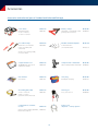
1
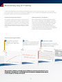
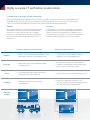
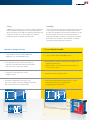
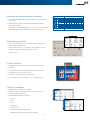
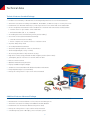
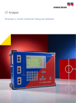
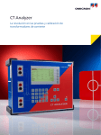
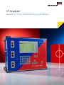
CT Analyzer
Revolution in current transformer testing and calibration
Revolutionary way of CT testing
Current transformers are used for relaying and metering purposes in electrical power systems. They connect the high
power primary side to the protection and metering equipment on the secondary side. Depending on the application they
are used for, current transformers are designed differently.
Protection current transformers
Metering current transformers
As it is used to feed protective relays, the CT must be accurate during normal and fault conditions. Failures in transformation could lead to misoperation of the relay along with
unwanted and costly outages. To test CTs according to the
requirements of modern protection systems, it is compulsory to consider transient components and auto-reclosure
systems.
CTs for metering purposes must provide high accuracy
up to class 0.1 to guarantee correct billing. It is therefore
essential to test and calibrate the metering current transformer, as the entire metering chain is only as accurate
as the instrument transformers feeding the meter.
In contrast to protection CTs, metering CTs must go into
saturation directly above the nominal primary current level
to protect the connected metering equipment.
Automated testing procedure
1 Measurement of parameters
Measurement of CT parameters
like excitation curve, eddy current,
ratio, etc.
2 Modeling
Definition of CT model elements and
calculation of CT parameters through
embedded mathematical functions
3 Assessment according
to IEEE or IEC standard
Automated comparison of test results
with the defined values according to the
selected IEEE or IEC standard
The CT Analyzer is designed to accurately measure all relevant CT parameters and compare them to the
requirements of the defined IEEE or IEC standard. Due to this automated assessment, testing engineers
receive the ‘pass or fail’ decision within seconds.
2
CT Analyzer – a new way of testing CTs
The CT Analyzer is the most complete testing system for protection and
metering CTs according to IEEE and IEC standards. It allows all types of single
and multi-ratio current transformers to be tested on-site in power system
grids. Manufacturers of CTs, transformers or GIS use the CT Analyzer in their
production facilities and test / development labs.
The CT Analyzer offers a wide range of measurements, such as:
> CT-ratio and phase-angle accuracy with consideration of
nominal and operational burden for various currents
> CT winding resistance
> CT excitation / saturation (unsaturated and saturated)
> ALF and FS (direct and indirect)
> Burden impedance
> CT residual magnetism
4 Reporting
All data is delivered in an XML file
and can be displayed via the
reporting tool
Your benefits
> Field verification of CTs up to the 0.1
accuracy class due to extremely high
accuracy (0.02 % typical)
> Compact and lightweight
(< 8 kg / 17.4 lbs)
> Automatic assessment in accordance
with IEEE and IEC standards
> Reduced testing time (typically < 1 min)
> High noise immunity for on-site testing
3
Highly accurate CT verification made mobile
The ideal way of testing a current transformer
As energy is supplied by many different sources, power system grids for generation, transmission and distribution are
expanded continuously. This makes the use of additional metering and protection CTs necessary. To test all of these
CTs in a cost-effective and reliable way, the ideal CT test device fulfills the following requirements:
Mobility
Accuracy
Test engineers often have to maintain several CTs within
one utility. The ideal CT test device would therefore be
an all-in-one solution, light enough to be carried by
one person. It should be able to measure all parameters
without the need for any further equipment (such as a
burden box).
Correct billing is only possible if metering CTs work within
their specifications, for all secondary burdens and levels of
primary current that are defined in the standards. To test
and calibrate these metering CTs, measurement equipment
delivering reliable results up to class 0.1 CTs is needed.
Mobility
Accuracy
Safety
Handling
Electrical
model
Primary nominal current injection
Primary current injection
> Approx. 2 tons of equipment (high current source,
> > 30 kg / 66.1 lbs (Not including additional
huge cables, current booster, burden box etc.)
> High accuracy, but complicated wiring makes
testing error-prone
> Not sufficient for high accuracy metering CTs
> Sensitive to transient distortion from life signals
(due to the use of 50 Hz test signals)
> Uses dangerously high voltages and currents
(primary nominal current injection)
> Typical current levels of 500 A to 800 A are used
> Re-wiring is required for each type of test
> Requires several people to set-up and
(e.g. ratio, polarity, saturation, winding resistance)
conduct the test
IP
equipment, e.g. external burden box)
> Test results must be assessed manually
IS
IP
IS
A
4
Safety
Handling
Equipment for testing CTs on-site must comply to applicable
safety standards and regulations. However, the ideal test
device avoids the use of high test currents and voltages and
conducts tests with as low test voltages as possible to
reduce the operator´s health and safety risks.
Short measurement times and an automated assessment
to the respective IEC and IEEE standards characterize
modern test equipment. All relevant parameters should
be measured in one test cycle without the need for
rewiring. Printable test reports, including all measured
data and the assessment to the standard, are ideally
created automatically by the test device.
Secondary voltage injection
> > 30 kg / 66.1 lbs (Not including additional
equipment, e.g. external burden box)
> Not sufficient for high accuracy metering CTs
Sensitive to transient distortion from life signals
(due to the use of 50 Hz test signals)
> Voltages for saturation tests can be
2,000 V or more
> Re-wiring is required for each type of test
(e.g. ratio, polarity, saturation, winding resistance)
CT as an electrical model
> < 8 kg / 17.4 lbs; ideal for handling on site
> Measurement of class 0.1 metering CTs Excellent noise
suppression guarantees
> Highly accurate on-site testing even if active lines are
close to the test object
> Maximum output voltage of 120 V
> One-step test determining all parameters (< 1 min)
> Automated assessment to standard and
> Test results must be assessed manually
VP
integrated report functionality
VS
U
VP
U
5
VS(f)
Extraordinary features
RemAlyzer
> Software-based tool to determine the residual magnetism in
current transformers
> Analysis of the remanence condition before putting into
operation the CT to assure proper function
> Simplifies power grid failure analysis after unwanted operation
of protective relays
> Demagnetizes the CT core after measurement
Remote control
> Full access to all functions of the CT Analyzer via a PC using
the remote interface
> Optimizes the integration into automated testing procedures in
production lines
> Data export into ExcelTM and WordTM
> Customizable testing and reports
Network simulation
> NetSim is a software tool for network simulation
(part of the Test Universe software suite for relay testing)
> Easy transfer of CT Analyzer measurement data to NetSim
> Accurate modeling of power systems for network studies and
fault simulation testing of protection relays
> Behavior analysis of protective relays in case of CT saturation
Data handling and reporting
> Test reports can be saved on the Compact Flash Card and
transferred to a PC
> Data and protocols can be shown on a PC via the
ExcelTM file loader program
> Customizable report templates are available, for example:
> Different standards, classes and applications
> Single, multi-core and multi-tap CTs
> Three-phase testing
> Core testing
6
Verification for different burdens and currents
POWER
> Existing measurement data can be loaded to the CT Analyzer
at any time
> Recalculation of the CT parameters for different burdens
and primary currents
> No further on-site measurements are necessary to verify whether
VA
cos Phi
15
0.8
7.5
0.8
3.75
1
0
1
Current ratio error in % at % of rated current
Data type
1%
5%
10%
20%
50%
100%
120%
String value
-0.023
-0.023
-0.021
-0.018
-0.013
-0.010
-0.009
-0.008
Float value
-0.023
-0.023
-0.021
-0.018
-0.013
-0.010
-0.009
-0.008
String value
-0.008
-0.010
-0.010
-0.008
-0.006
-0.004
-0.003
-0.002
Float value
-0.008
-0.010
-0.010
-0.008
-0.006
-0.004
-0.003
-0.002
String value
0.005
0.001
0.000
-0.001
0.000
0.000
0.001
0.001
Float value
0.005
0.001
0.000
-0.001
-0.000
0.000
0.001
0.001
String value
0.007
0.005
0.004
0.003
0.003
0.003
0.004
0.004
Float value
0.007
0.005
0.004
0.003
0.003
0.003
0.004
0.004
a change in the burden will influence the accuracy of a CT
Manual testing: QuickTest
> Use of the CT Analyzer as a multimeter with an integrated
current and voltage source
> Perform manual tests (L, Z, R, ratio, polarity, burden etc.) for
trouble-shooting and quick verification on site
> VT ratio check
CT SB2 switch box
> Automated testing of multi-tap CTs without the need for
rewiring
> Includes terminals for burden and primary resistance tests
> CTs with up to six taps can be tested
> Automatic wiring check before measuring
> Use attached to the CT Analyzer or as a standalone unit
„Guessing“ nameplates
> Determination of unknown CT data
before test
> Older CTs can be classified and put into service without
contacting the manufacturer
> Determinable parameters include:
> CT type
after test
> Class
> Ratio
> Knee point
> Power Factor
> Nominal and operating burden
> Winding resistance (primary and secondary)
7
200%
Technical data
Technical features Standard Package
>> Excellent noise immunity to disturbances from energized power lines close to the measurement
>> Automatic assessment according to IEC 60044-1, IEC 61869-2, or IEEE C57.13 up to accuracy class ≥ 0.3
>> Determination of ALF/ALFi and FS/FSi, Ts, and composite error for nominal and connected burden
>> CT ratio and phase measurement with consideration of nominal and connected secondary burden
>> Currents from 1% up to 400 % of the rated value
>> Different burdens (full, ½, ¼, ⅛ burden)
>> CT winding resistance measurement (primary and secondary)
>> CT excitation curve (unsaturated and saturated)
>> Saturation characteristic recording
>> Direct comparison of excitation curve to a reference curve
>> CT phase and polarity check
>> Secondary burden measurement
>> Automatic demagnetization of the CT after the test
>> Small and lightweight (< 8 kg / 17.4 lbs)
>> Short testing time due to fully automatic testing
>> High level of safety using patented variable frequency method (max. 120 V)
>> „Nameplate guesser“ function for CTs with unknown data
>> Remote control interface
>> QuickTest: Manual testing interface
>> Display readable in bright sunlight
>> Simulation of measured data with different burdens and currents
>> Easily adaptable reports (customizable)
>> Knee-point voltage from 1 V up to 4 kV can be measured
Additional features Advanced Package
>> Automatic assessment for accuracy class > 0.1 (inclusive classes defined in the IEEE C57.13.6 standard)
>> Measurement of transient behavior of TPS, TPX, TPY and TPZ type CTs
>> Automatic assessment according to IEC 60044-6 and IEC 61869-2
>> Determination of the transient dimensioning factor (Ktd)
>> Knee-point voltage from 1 V up to 30 kV can be measured
>> Considering Duty (C-O / C-O-C-O) e.g. auto-reclosure system
8
Technical data CT Analyzer
Current ratio accuracy
Physical dimensions
Ratio 1 ... 2000
0.02 % (typical) / 0.05 % (guaranteed)
Ratio 2000 ... 5000
0.03 % (typical) / 0.1 % (guaranteed)
Ratio 5000 ... 10000
Size (W × H × D)
360 × 285 × 145 mm /
9.2 × 7.2 × 3.7 in
Weight
8 kg / 17.4 lbs (without accessories)
0.05 % (typical) / 0.2 % (guaranteed)
Environment conditions
Operating temperature -10 °C ... + 50 °C / 14 °F ... 122 °F
Phase displacement
Storage temperature
-25 °C ... + 70 °C / -13 °F ... 158 °F
Resolution
0.1 min
Humidity
Relative humidity 5 % ... 95 % not condensing
Accuracy
1 min (typical) / 3 min (guaranteed)
Winding resistance
CE conformity
Resolution
1 mΩ
(EMC) Directive 2004/108/EC and low-voltage Directive 2006/95/EC
Accuracy
0.05 % (typical) /
0.1 % + 1 mΩ (guaranteed)
Power supply
Input voltage
100 VAC ... 240 VAC
Permissible input voltage
85 VAC ...264 VAC
Frequency
50 / 60 Hz
Permissible
frequency
45 Hz ... 65 Hz
Input power
500 VA
Connection
Standard AC Socket IEC 60320
EMC
EN 61326-1 Class A, IEC 61326-1 Class A,
FCC Subpart B of Part 15 Class A
Safety
EN 61010-1
IEC 61010-1
UL 61010-1
CSA C22.2 No. 1010.1-92
Certificates from independent test institutes
KEMA Test Report
PTB Test Report
Wuhan HV Research Test Report
Output
Output voltage
0 ... 120 VAC
Output current
0 ... 5 Aeff (15 Apeak)
Output power
0 ... 400 VAeff (1500 VApeak)
Ordering information
Description
Order No.
Standard Package
VE000656
Advanced Package
VE000654
Upgrade Standard – Advanced
VESM0653
9
Accessories
Accessories and software (part of Standard and Advanced Package)
Coax cables
Order No.
Battery clamps
Order No.
with banana plugs
2 × 3 m / 2 × 9.8 ft,
1 × 10 m / 1 × 32.8 ft
VEHK0651
with 4 mm / 0.2 in banana sockets
(primary side connection)
VEHZ0652
Crocodile clamps
Order No.
Flexible terminal adapters
Order No.
with 4 mm / 0.2 in banana
sockets (secondary side
connection)
VEHZ0656
1 with 12 × 4 mm /
0.2 in banana socket
VEHS0009
20 mm / 0.8 in opening width,
2 × red, 2 × black
Compact Flash Card
Order No.
Compact Flash card reader
Order No.
128 MB Memory space for at
least 416 test reports
VEHZ0654
USB 2.0 Compact Flash card reader
VEHZ0655
User manual
Order No.
Carry bag
Order No.
User manual
VESD0605
CT Analyzer carry bag
VEHP0018
Grounding (PE) cable
Order No.
Training CT
Order No.
1 × 6 m / 1 × 19.7 ft,
6 mm² / 0.01 sq in,
(protective earth connection)
VEHK0615
300:5, class 0.5 FS 5
VEHZ0643
Order No.
Power cord
depends – country-specific
CT Analyzer PC software
toolset
remote control software, QuickTest, VESM0800
ExcelTM File Loader etc.
10
Additional accessories and software
Calibration CT
Order No.
Coax cables
Order No.
2000:1 / 2000:5,
class 0.02
VEHZ0649
3 m / 9.8 ft*
6 m / 19.7 ft*
10 m / 32.8 ft*
15 m / 49.2 ft*
100 m / 328.1 ft*
VEHK0654
VEHK0652
VEHK0653
VEHK0655
VEHK0656
* with banana plugs
Pluggable winding
Order No.
Transport case
Order No.
Pluggable 23 turns winding
VEHK0658
Transport case with wheels
VEHP0068
CT SB2 upgrade kit
Order No.
USB – RS232 converter cable
Order No.
CT SB2, accessories included
VEHZ0696
with Nullmodem cable
VEHZ0014
Primary resistance Kit
Order No.
4 pole cable 15 m / 49.2 ft (CT SB2 to CTprim),
2 × Kelvin clamps
VEHZ0684
RemAlyzer
Order No.
Software License for the
CT Analyzer to determine
the residual magnetism in
current transformers
VESM0657
Set of two Kelvin clamp
adapters
Kelvin clamp adapter can be
used together with the standard
measurement cable
11
Order No.
VEHZ0628
OMICRON is an international company serving the electrical power industry with
innovative testing and diagnostic solutions. The application of OMICRON products
allows users to assess the condition of the primary and secondary equipment on
their systems with complete confidence. Services offered in the area of consulting,
commissioning, testing, diagnosis and training make the product range complete.
Customers in more than 140 countries rely on the company’s ability to supply leadingedge technology of excellent quality. Service centers on all continents provide a broad
base of knowledge and extraordinary customer support. All of this together with our
strong network of sales partners is what has made our company a market leader in the
electrical power industry.
The following publications provide further information on the solutions described in this
brochure:
CT SB2
Multi-Ratio Switch-Box for CT Analyzer
The CT SB2 Switch-Box is an accessory for the CT Analyzer that
enables the automatic testing of multi-ratio current transformers
(CTs) with up to 6 tap connections (X1 to X6). The CT SB2 is
connected to all the taps of a multi-ratio CT as well as to the CT
Analyzer. Thus every ratio combination can be tested automatically
by the CT Analyzer.
Convenient Features
The CT SB2 offers many convenient features for testing:
•
6 channel secondary connection terminals
•
Color-coded terminals and cables to avoid connection errors
•
Automatic wiring check to help with trouble-shooting
•
Easy test setup using the CT Analyzer User Interface
•
Terminals for connection of primary resistance and secondary
burden for full automatic test without re-wiring during test
Mobile – Compact – Automated
Depicted: CT SB2
Flexibility on-site
The CT SB2 can be easily attached to the CT Analyzer or placed
separately beside. With a combined weight of 11 kg / 24 lbs,
the CT Analyzer with the CT SB2 is convenient to carry and handle
on-site. The CT SB2 makes the CT Analyzer the most flexible and
complete solution for testing multi-ratio CTs.
CT SB2
Input Voltage
Scope of Delivery CT SB2
100 - 240 V
Input Frequency
50 - 60 Hz
Input Current
0.2 A
Output Voltage*
0 - 120 V
Output Current*
0-5A
Output Power*
0 - 400 VA
Dimensions (W x H x D)
284 x 220 x 68 mm
11.2 x 8.7 x 2.7 in
Weight
2.6 kg / 5.7 lbs
Order Number
VEHZ0696
* Output of CT Analyzer
Datasheet CT SB2
Switch Box
For more information, additional literature, and detailed contact information of our
worldwide offices please visit our website.
www.omicron.at | www.omicronusa.com
© OMICRON L2065, August 2013
Subject to change without notice.