1
ISIO 200
User Manual
Manual Version: ISIO200.AE.1 – 2013-11
© OMICRON electronics. All rights reserved.
This manual is a publication of OMICRON electronics.
All rights including translation reserved. Reproduction of any kind, for example photocopying,
microfilming, optical character recognition and/or storage in electronic data processing systems,
requires the explicit consent of OMICRON electronics.
Reprinting, wholly or in part, is not permitted. The product information, specifications, and technical
data embodied in this manual represent the technical status at the time of writing and are subject to
change without prior notice.
We have done our best to ensure that the information given in this manual is useful, accurate and
entirely reliable. However, OMICRON electronics does not assume responsibility for any inaccuracies
that may be present.
The user is responsible for every application that makes use of an OMICRON product.
OMICRON electronics translates this manual from the source language English into a number of other
languages. Any translation of this manual is done for local requirements, and in the event of a dispute
between the English and a non-English version, the English version of this manual shall govern.
Contents
Contents
1
Preface and general safety instructions .................................................................................... 6
1.1 Safety instructions ...............................................................................................................6
1.1.1
1.1.2
1.1.3
1.1.4
1.1.5
1.2
2
For your safety please note.................................................................................................... 6
Rules for use......................................................................................................................... 6
Orderly practices and procedures .......................................................................................... 7
Operator qualifications........................................................................................................... 7
Safe operation procedures..................................................................................................... 7
Designated use ...................................................................................................................7
Scope of delivery ........................................................................................................................8
2.1 Spare parts ....................................................................................................................... 10
2.1.1 Power connector ................................................................................................................. 10
2.1.2 Binary I/O connector ............................................................................................................ 10
3
Device overview........................................................................................................................ 11
3.1 Front panel........................................................................................................................ 11
3.2 Rear panel ........................................................................................................................ 12
4
Mounting ................................................................................................................................... 13
4.1 DIN rail mounting .............................................................................................................. 13
4.1.1 Assemble DIN rail clip to the ISIO 200.................................................................................. 13
4.1.2 Typical mounting position on DIN rail ................................................................................... 13
4.1.3 Removing ISIO 200 from DIN rail ......................................................................................... 13
4.2
4.3
Wall mount ........................................................................................................................ 14
Tabletop use ..................................................................................................................... 14
5
Power supply ............................................................................................................................ 15
5.1 Power over Ethernet.......................................................................................................... 15
5.2 Power input ....................................................................................................................... 15
6
Communication and access ..................................................................................................... 16
6.1 OMICRON Device Browser ............................................................................................... 16
6.1.1
6.1.2
6.1.3
6.1.4
6.2
7
Installing the OMICRON Device Browser ............................................................................. 16
Finding OMICRON devices in the device browser manually (OMFIND) ................................. 16
Setting an IP address with the OMICRON Device Browser ................................................... 16
Accessing the web interface from the OMICRON Device Browser ......................................... 16
Web Browser .................................................................................................................... 16
Configuration and web interface.............................................................................................. 17
7.1 Security certificate ............................................................................................................. 17
7.2 Homepage ........................................................................................................................ 17
7.2.1 Authentication ..................................................................................................................... 17
3
ISIO 200
7.2.2 Time and system status ....................................................................................................... 17
7.3
Network ............................................................................................................................ 18
7.3.1 Network interface ................................................................................................................ 18
7.3.2 Device discovery ................................................................................................................. 18
7.4
GOOSE ............................................................................................................................ 19
7.4.1 Default and custom GOOSE configuration............................................................................ 19
7.4.2 Matching pairs of ISIO 200 .................................................................................................. 20
7.4.3 Restarting the GOOSE application ....................................................................................... 20
7.5
7.6
7.7
GOOSE Subscription ........................................................................................................ 20
GOOSE Publishing ........................................................................................................... 20
Custom GOOSE configuration........................................................................................... 21
7.7.1 Uploading a custom GOOSE configuration ........................................................................... 22
7.8
Download .......................................................................................................................... 23
7.8.1 Downloading the configuration in SCL format ....................................................................... 24
7.8.2 Downloading the configuration for usage with a CMC ........................................................... 25
7.9
Hardware .......................................................................................................................... 26
7.9.1 Input settings....................................................................................................................... 26
7.9.2 Input / output status ............................................................................................................. 26
7.9.3 Component information ....................................................................................................... 26
7.10 Time ................................................................................................................................. 27
7.10.1 Internal clock....................................................................................................................... 27
7.10.2 NTP .................................................................................................................................... 27
7.10.3 PTP .................................................................................................................................... 27
7.11 System.............................................................................................................................. 28
7.11.1
7.11.2
7.11.3
7.11.4
7.11.5
Status ................................................................................................................................. 28
Maintenance ....................................................................................................................... 28
Firmware upgrade ............................................................................................................... 28
Change password ............................................................................................................... 29
Licenses information............................................................................................................ 29
8
Resetting the device ................................................................................................................. 30
8.1 Reboot .............................................................................................................................. 30
8.2 Reset to factory defaults .................................................................................................... 30
8.3 Recovery mode ................................................................................................................. 30
9
Open source software license information ............................................................................. 31
10 Technical data........................................................................................................................... 32
10.1 Power supply .................................................................................................................... 32
10.1.1 Power over Ethernet ............................................................................................................ 32
10.1.2 Power input ......................................................................................................................... 32
10.2 Insulation coordination ...................................................................................................... 32
4
Contents
10.3 Binary inputs ..................................................................................................................... 33
10.4 Binary outputs ................................................................................................................... 35
10.5 Communication ................................................................................................................. 36
10.5.1 Protocols............................................................................................................................. 36
10.5.2 IEC 61850 GOOSE ............................................................................................................. 36
10.6 Time synchronization ........................................................................................................ 37
10.7 Environmental conditions .................................................................................................. 37
10.7.1 Climate ............................................................................................................................... 37
10.7.2 Shock and vibration ............................................................................................................. 37
10.8 Mechanical data ................................................................................................................ 38
10.9 Cleaning............................................................................................................................ 38
10.10 Safety standards, Electromagnetic Compatibility, certificates ............................................. 38
Glossary .......................................................................................................................................... 40
OMICRON service centers .............................................................................................................. 41
Index ................................................................................................................................................ 42
5
ISIO 200
1
Preface and general safety instructions
The purpose of this manual is to familiarize users with the ISIO 200 and to show how to properly use
it. The manual contains important tips on how to use the ISIO 200 safely, properly, and efficiently. Its
purpose is to help you avoid danger, repair costs, and down time as well as to help maintain the
reliability and life of the ISIO 200.
This manual is to be supplemented by existing national safety standards for accident prevention and
environmental protection. Keep it available at the site where the ISIO 200 is used. It should be read by
all personnel operating the device. In addition to the manual and the applicable safety regulations in
the country and at the site of operation, heed the usual technical procedures for safe and competent
work.
This manual describes the ISIO 200 device and its built in configuration interface. In order to get
familiar with the referenced software for advanced GOOSE configuration (The GOOSE Configuration
module), please refer to the OMICRON Test Universe and the accompanying software manuals.
1.1
Safety instructions
Before operating the ISIO 200, carefully read the following safety instructions. Only operate the
ISIO 200 after you have read this manual and fully understood the instructions herein.
The ISIO 200 may only be operated by trained personnel. Any maloperation can result in damage to
property or persons.
1.1.1
For your safety please note
The binary I/O terminals of the ISIO 200 test set can conduct life-hazardous voltages.
Throughout the manual, this symbol indicates special safety-relevant
notes/directions linked to the possibility of touching live voltages and/or currents.
Please thoroughly read and follow those directions to avoid life-hazardous
situations.
This symbol indicates potential hazards by electrical voltages/currents caused by,
for example, wrong connections, short-circuits, technically inadequate or faulty
equipment or by disregarding the safety notes of the following sections.
1.1.2
Rules for use
• The ISIO 200 must only be used when in a technically sound condition. Its use must be in
accordance with the safety regulations for the specific job site and application. Always be aware
of the dangers of high voltages. Pay attention to the information provided in the documentation.
• The ISIO 200 is exclusively intended for the application areas specified in section 1.2 on page 7.
The manufacturer/distributors are not liable for damage resulting from unintended usage.
The user alone assumes all responsibility and risk.
• The instructions provided in this manual and the associated software manuals are considered
part of the rules governing proper usage.
• Do not open the ISIO 200 or remove any of its housing components.
6
Preface and general safety instructions
1.1.3
Orderly practices and procedures
• Keep this manual available on site where the ISIO 200 is used.
• Personnel assigned to using the ISIO 200 must have read this manual and fully understood the
instructions herein.
• Do not carry out any modifications, extensions or adaptations at the ISIO 200.
1.1.4
Operator qualifications
• Installation and configuration of the ISIO 200 should only be carried out by authorized and
qualified personnel.
• Personnel receiving training, instruction, direction, or education on the ISIO 200 should remain
under the constant supervision of an experienced operator while working with the equipment.
1.1.5
Safe operation procedures
• Follow the instructions in sections 2 to 8 that describe how to set the setup and use of the
ISIO 200.
• Do not use any other power supply options for the ISIO 200 than the ones described in section 5
on page 15.
• Before wiring the terminals, verify that the conducting parts are de-energized.
The terminal connectors have hazardous live parts.
• Product safety according to IEC 61010-1 is only achieved by operating the ISIO 200 in a secured
area (with safety barrier and safety indicator) or in permanent/stationary setups.
• Do not operate the ISIO 200 under wet or moist conditions (condensation).
• Do not operate the ISIO 200 when explosive gas or vapors are present.
• If the ISIO 200 is opened by unauthorized personnel, all guarantees are invalidated.
• Connect the ETH connector only to Ethernet ports.
• If the ISIO 200 seems to be functioning improperly, please contact the OMICRON Technical
Support, →“OMICRON Service Centers” on page 41.
1.2
Designated use
The ISIO 200 is a binary I/O terminal to be used in protection and automation systems for electrical
power utilities that utilize GOOSE according to IEC 61850.
The ISIO 200 performs a conversion between its binary I/Os and IEC 61850 GOOSE messages.
The information carried with the subscribed (received) GOOSE messages is output at the binary
outputs. The status of the binary inputs is published (sent out) via GOOSE messages.
The ISIO 200 may be either:
• a portable accessory for testing protection and power utility automation systems
• permanently installed as a test terminal
• permanently installed to perform operational functions in protection and power utility automation
systems
Any other use of the ISIO 200 is considered improper and may result in damage to property or
persons.
7
ISIO 200
Matched pairs
When two ISIO 200 devices are set up accordingly, the binary I/O status sensed on the inputs of one
device will be mirrored on the output of the other device. To utilize this feature right out of the box
without further configuration, the devices can be delivered in matched pairs. For the setup of arbitrary
ISIO 200 devices for this use, see section 7.4.2 on page 20.
2
Scope of delivery
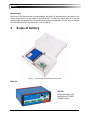
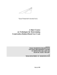
Figure 1:
ISIO 200 with accessories at delivery in box
Main unit
ISIO 200
Binary Input/Output (I/O)
terminal with IEC 61850
GOOSE interface
8
Scope of delivery
Accessories included with delivery
Binary I/O connector: MSTB 2.5HC/5-STF-5.08
4 x 5 pin connector for binary I/O terminals
Power connector: MC 1.5/2-STF-3.81
1 x 2 pin connector for POWER
DIN rail mounting clip: Hutsclip/AL/0009
DIN rail mounting clip for 35 mm top hat rail according to
IEC 50022 including 2x M3x12 (TX10).
For assembling the clip to the ISIO 200 please refer to
section 4.1.1 on page 13.
Mounting brackets: AB-WL 3
Brackets for mounting the ISIO 200 on a flat surface (a wall
mounting, for example).
For detailed assembling information please refer to
section 4.2 on page 14.
Welcome letter and quick start guide
Hardcopies of instructions for initial use.
Recommended accessories for laboratory use
These adapter cables are recommended for the laboratory use according to IEC 61010-1.
Terminal Adapters: 1 pole FLEXI-2V black 4 mm isolated
Flexible 2.5 mm² adapter, inclusive 4 mm banana jack
OMICRON article number: VEHS0009
One article contains 12 flexible terminal adapters for screwtype terminals, so two of them are required for serving all
terminals of one ISIO 200.
The use of these adapters alone does not comply with the requirements of
IEC 61010-1. Be aware that a secured operating environment is necessary
(see section "Safe operation procedures" on page 7).
9
ISIO 200
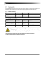
2.1
Spare parts
The recommended connectors for the power input and the binary I/O terminals are included in the
accessories. Other variants may be more suited for specific applications and are listed below.
2.1.1
Power connector
Type
Manufacturer
Purchase code
Comment
MC 1.5/2-STF-3.81
Phoenix Contact
1827703
with screw connection
284511-2
TE Connectivity
284511-2
with screw connection
2.1.2
Binary I/O connector
Type
Manufacturer
Purchase code
Comment
MSTB 2.5/ 5-STF-5.08
Phoenix Contact
1912210
with screw connection
796859-5
TE Connectivity
796859-5
with screw connection
FKC 2.5 HC/ 5-STF-5.08
Phoenix Contact
1942510
with spring-cage connector
MSTBC 2.5/ 5-STZF-5.08
Phoenix Contact
1809763
with crimp connection
These connectors are safe according to IEC 61984 and IEC 60999-1.
They are required for the use in substation automation systems according to
IEC 60255-27. Be aware that a secured operating environment is necessary
(see section "Safe operation procedures" on page 7).
These connectors are available from many major distributors for electrical components.
The spare connectors cannot be ordered from OMICRON.
10
Device overview
3
Device overview
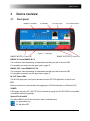
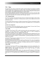
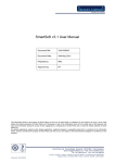
3.1
Front panel
BINARY I/O Status
ETHERNET
Figure 2:
STATUS LEDs
DC POWER INPUT
Front panel
BINARY INPUTS (1-4 and 5-8)
BINARY OUTPUTS (1-4 and 5-8)
BINARY IN 1-4 and BINARY IN 5-8
Two connectors, each representing an independent potential group with a common GND.
For compatible connectors, see the spare parts on page 10.
BINARY OUT 1-4 and BINARY OUT 5-8
Two connectors, each representing an independent potential group with a common GND.
For compatible connectors, see the spare parts on page 10.
IN / OUT Status LEDs
The IN LEDs lights green if an input is stimulated and the OUT LEDs lights red if an output is set.
ETH
Ethernet connector for communication and supplying the ISIO 200 with power over Ethernet (PoE).
POWER
A DC supply connector (MC 1.5/2-STF-3.81) to alternatively supply the ISIO 200 if PoE is not available
is included in the delivery package.
Status LEDs S1 and S2
The status LEDs S1 and S2 are of interest in case of troubleshooting:
S1: green status LED
S2: red status LED
11
ISIO 200
S1 and S2 continuously off
The ISIO 200 is not supplied with power.
S1 off
S2 lights red
Reboot is in progress.
S1 off
S2 flashes red
Software update is in progress.
Attention: Do not disconnect the ISIO 200 device from the Ethernet
during the software update.
S1 lights green and
S2 lights red
Intermediate state when entering the recovery mode manually or
when initiating a factory reset (see also section 8 on page 30).
S1 flashes green
S2 off
The ISIO 200 is in the recovery mode, waiting for new software.
In the recovery mode, the device provides only a rudimentary web
interface, only to allow the upload of a software image
(see also section 8.3 on page 30).
S1 lights green
S2 off
The ISIO 200 is ready for operation.
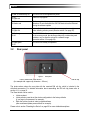
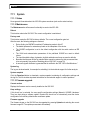
3.2
Rear panel
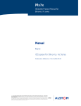
Figure 3:
Rear panel
Hole to access the Reset button
(for example with a paper clip, diameter < 0.9 mm)
DIN rail clip
The picture above shows the rear plate with the mounted DIN rail clip, which is included in the
delivered accessories. For detailed information about assembling the DIN rail clip please refer to
section 4.1.1 on page 13.
The Reset button can be used to:
• Initiate a reboot.
• Initiate a factory reset to set the device configuration to the factory defaults
(if you forgot your password, for example).
• Enter the recovery mode in order to upload software
(after a software update process failed, for example).
Please refer to section "Resetting the Device" on page 30 for more detailed descriptions.
12
Mounting
4
Mounting
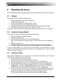
4.1
DIN rail mounting
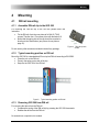
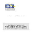
4.1.1
Assemble DIN rail clip to the ISIO 200
For mounting the DIN rail clip to the ISIO 200 please follow this
instruction:
• Fix the DIN rail clip to the rear plate via 2x M3x12 (TX10)
screws. Therefor use a Torx screw driver with dimension 10.
• Notice that the spring side of the clip should be mounted in
direction to the Reset button (see picture of rear plate on
page 12).
Figure 4:
Do not use any other screws as included in the delivery package.
4.1.2
DIN rail clip with
screws
Typical mounting position on DIN rail
Mount the ISIO 200 to a standardized 35 mm top hat DIN rail according to EN 50022.
•
•
•
Place the unit on the DIN rail.
Press-in the spring on top side of the clip.
Snap-On the ISIO 200 to the DIN rail.
Figure 5:
4.1.3
Typical mounting position on DIN rail
Removing ISIO 200 from DIN rail
For removing the device from the DIN rail:
•
•
Compress the spring of the DIN rail clip by pressing the ISIO 200 downwards.
Release the device from the DIN rail.
No screw driver or special tool is needed.
13
ISIO 200
4.2
Wall mount
For mounting the ISIO 200 on a flat surface (a wall mounting, for
example), the mounting brackets are included in the delivery package.
Please follow the included instruction leaflet for assembling the brackets
to the ISIO 200.
•
•
•
4.3
Remove the black screw covers and screws.
Insert the included seal rings.
Fix the brackets to the device via the included 22 mm screws.
Figure 6:
Mounting brackets
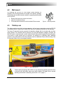
Tabletop use
The rubber sealings around the housing guarantee a soft and secure stand when using the ISIO 200
as a tabletop device. A typical use is with a CMC test set in a temporary test setup or in a laboratory.
The binary I/O terminals may be connected to hazardous voltages and do not protect the user from
electric shocks. The connector itself may become a live part with hazardous voltages. Therefore, the
ISIO 200 must be mounted inside a control cabinet that provides protection against touching life parts.
If the device is used outside such an enclosure, for example on a laboratory desk, additional
protection using safety barriers and safety indicators must be established. Ensure that the wiring of the
I/O terminals is done only in de-energized condition.
Figure 7:
Typical tabletop use
Product safety according to IEC 61010-1 is only achieved by operating the ISIO 200 in
a secured area (with safety barrier and safety indicator). Be aware that a secured
operating environment is necessary (see section 1.1.5 on page 7).
14
Power supply
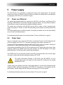
5
Power supply
The ISIO 200 offers two possibilities for supplying the device with electrical power. The preferred
method is by Power over Ethernet. When no Power over Ethernet is available there is the alternative
by supplying the ISIO 200 over an external DC supply.
5.1
Power over Ethernet
The easiest and preferred method for supplying the ISIO 200 is with Power over Ethernet (PoE)
according to IEEE 802.3af. The insulation concept is optimized therefor. The same Ethernet cable for
communication is used for powering and no additional cabling is required.
The network port connected to the ISIO 200 must be able to supply a class 2 powered device
(Power Consumption < 6.49 W). The ISIO 200 automatically powers up after connecting the Ethernet
cable.
If no PoE compatible source (an Ethernet switch, for example) is available, there is also the possibility
to use a Power over Ethernet injector.
For detailed specification please refer to technical data of "Power over Ethernet" on page 32.
5.2
Power input
There is an alternative way to power the ISIO 200 by an external DC supply. The ISIO 200 works with
a DC input voltage from 18 V to 57 V. The power consumption of the device is less than 5 W.
Connect the DC supply via terminal connector (MC 1.5/2-STF-3.81), which is included in accessories
(see section 2), to the POWER input and the ISIO 200 automatically powers up.
If both powering possibilities of the ISIO 200 are connected, the DC Power Input gains priority. When
supplying voltage to the POWER input during PoE operation, the ISIO 200 changes to DC supply
without rebooting. The PoE supply will be deactivated automatically.
The POWER input is only functionally isolated to the SELV group and therefore the external supply
unit needs to comply with the safety standard according to IEC 61140.
The safety requirements according to IEC 61010-1 and IEC 60255-27 are only
complied with by using a DC supply unit that provides SELV (safety extra low voltage)
regarding IEC 61140.
A power supply with a galvanic connection to the station battery of a power utility automation system
violates the safety requirements according to IEC 60255-27. If the device is to be supplied from the
station battery, a power supply with SELV insulation according to IEC 61140 is required.
For detailed specifications please refer to technical data of "Power input" on page 32.
15
ISIO 200
6
Communication and access
6.1
OMICRON Device Browser
The OMICRON Device Browser (ODB) is a component to find OMICRON devices on a local network
even if the IP address of the device is not known yet. When an ISIO 200 is found and listed by the
ODB, further functions can be applied. Two functions of particular interest are:
• Setting a static IP address for the ISIO 200.
• Invoking the web interface of the ISIO 200.
6.1.1
Installing the OMICRON Device Browser
The ODB installer for MS-Windows operating systems can be downloaded from the ISIO 200 website.
Go to the ISIO 200 product page. The download link for the OMICRON Device Browser is provided
there. Execute the downloaded installer to install ODB on your computer. An icon with the label
OMICRON Devices will be placed on the desktop.
6.1.2
Finding OMICRON devices in the device browser manually (OMFIND)
Normally, the ODB automatically finds the OMICRON devices connected to the network. If not, it is
also possible to manually search the network for available OMICRON devices.
Proceed as follows:
• Right-click the OMICRON Devices desktop icon.
• On the context menu, select OMFind and then click Find Devices.
• This will start the Device Discovery tool. This tool is intended to diagnose network/firewall
problems when the Device Browser lists no or not all expected devices.
• Click the Start Discovery button to manually search for OMICRON devices connected to the
network. Once the search is finished, the discovered devices section lists network parameters of
all found OMICRON devices.
Clicking on the on the ODB icon will open the browser, presenting a list of found OMICRON devices.
6.1.3
Setting an IP address with the OMICRON Device Browser
The OMICRON Device Browser can be used to assign a static IP address to the ISIO 200.
• Right-click the ISIO 200 device symbol, select Set Network Configuration …
• Enter the IP settings and apply them
6.1.4
Accessing the web interface from the OMICRON Device Browser
The ISIO 200 web interface can be directly accessed through the OMICRON Device Browser:
• Right-click the ISIO 200 device symbol, select Open Web Interface.
• The start page of the ISIO 200 web interface will open in the default web browser on your
computer.
6.2
Web Browser
The web interface can be invoked by entering the IP address of the ISIO 200 as the URL in a browser.
16
Configuration and web interface
7
Configuration and web interface
The ISIO 200 hosts a web server for providing status information and configuration via a web
interface.
7.1
Security certificate
The ISIO 200 uses a secure HTTPS connection to the PC. The HTTPS protocol requires a security
certificate to be present when a server (ISIO 200) and client (PC with web browser) connect.
With the ISIO 200, the self-signed certificate method is used and a certificate is generated when such
a connection is established for the first time. The browser will display a corresponding message that
has to be acknowledged. This certificate remains valid for the specific client/server pair and following
connections will be established without further overhead.
A self-signed certificate is initially created that is certified to the hostname “ISIO-<SerialNumber>”. The
browser will display a security warning when accessing the ISIO 200. This has to be acknowledged
and/or installed in the browser to avoid further security warnings.
The installed certificate will be not or no longer valid, when
• another PC is used to connect to the ISIO 200 or
• the same PC, but another web browser is used.
To avoid the situation with the changed IP address of the ISIO 200 during an established connection
to the web interface, it is recommended to use the OMICRON device browser and to set the IP
address before the ISIO 200 is accessed via a web browser for the first time.
7.2
Homepage
The homepage of the ISIO 200 is displayed when connecting to the ISIO 200 with a browser by
specifying the device's IP address or URL.
Clicking the ISIO 200 logo in the upper left corner redirects to the homepage.
7.2.1
Authentication
The web interface can be only accessed after a successful login. The default password at delivery is
printed on the nameplate on the bottom side of the ISIO 200.
Once logged in the logout function is presented in this place.
An automatic logout will occur when the user interface is not actively used for 15 minutes.
7.2.2
Time and system status
Selected general information about the device is displayed in these sections.
17
ISIO 200
7.3
Network
7.3.1
Network interface
Auto-IP
At delivery, the ISIO 200 is set for using Auto-IP to avoid conflicts and network problems when
multiple, not yet configured ISIO 200 devices are connected to a common network. Although the
obtained Auto-IP addresses are not known and therefore not usable, it is assured that all devices have
unique IP addresses.
Static
Static IP is the most important mode for a substation automation device like the ISIO 200. During the
planning of the SAS, the IP addresses are assigned to the IEDs and such an address has to be
configured statically in the ISIO 200.
As a consequence of changing the IP address using the web interface, the connection to the ISIO 200
gets lost. A new connection using the new IP address has to be established. For the implications
concerning the security certificate, see section 7.1 on page 17.
DHCP
DHCP is provided for completeness only and for some rare use cases. There is no likely use for this
mode in real applications, unless a DHCP server is explicitly configured to assign predefined IP
addresses to certain devices (identified by their MAC address).
IP Address, Mask, and Gateway
When the ISIO 200 is in Static IP mode, the IP address setting values have to be specified here. The
MAC address and the link speed are displayed.
7.3.2
Device discovery
The device discovery protocols OMFIND and Zeroconf are provided for finding the ISIO 200 in local
networks even if the IP address of the device is not yet known. For this purpose, they are enabled at
delivery. Since these protocols are not security hardened, it is recommended to disable them after the
initial setup of the ISIO 200 when cyber security is a concern.
OMFIND is an OMICRON proprietary method to discover OMICRON devices, such as test sets. The
OMICRON Device Browser (ODB) for MS-Windows operating systems makes use of this method. The
ODB is installed with many OMICRON software packages, such as the OMICRON Test Universe. A
standalone installer for the ODB can be downloaded from the OMICRON homepage (see
section 6.1.1 on page 16).
Zeroconf is a device finding method used in many consumer devices, such as home routers or
network storage devices. This function is just provided for convenience and only "as is" without
guarantee of its function or specific features.
18
Configuration and web interface
7.4
GOOSE
7.4.1
Default and custom GOOSE configuration
Default configuration
In the default configuration, the number of used GOOSE messages and the GOOSE dataset is
predefined.
The ISIO 200 subscribes to exactly one GOOSE message and publishes exactly one GOOSE
message.
The dataset contains eight Boolean attributes (one for each binary input or output). Each of these
Boolean attributes is accompanied by its quality attribute (of type BitString[13]).
The following figure illustrates how such a dataset would be represented in the GOOSE Configuration
module of the OMICRON Test Universe software.
Figure 8:
Dataset layout for the default GOOSE configuration with typical object references
This applies for the subscribed and the published GOOSE as well. This default configuration is the
precondition for the operation of matched pairs (see section 7.4.2 on page 20) and for the availability
of the download functions for the current configuration.
Custom configuration
When a custom configuration is selected, a configuration file needs to be uploaded to the ISIO 200.
The corresponding controls are displayed as soon as the custom configuration is selected.
A custom GOOSE configuration needs to be set up with external tools. For the details of this custom
configuration process, see the sections 7.7 on page 21 and 7.8 on page 23.
The Subscription, Publishing, and Download page are not accessible any more when a custom
configuration is applied.
19
ISIO 200
7.4.2
Matching pairs of ISIO 200
A matched pair of ISIO 200 devices is preconfigured at delivery to communicate with each other "outof-the-box". There is no further configuration needed. When two paired devices (the peers) are
connected to the same network (or more specifically: to the same broadcast domain), they will
immediately exchange their binary I/O status. This means, the information sensed at the inputs of one
device will be output at the outputs of the peer device.
Of course, other devices can subscribe to the GOOSE messages published by such a pair of ISIO 200
and access the information transmitted.
Matching an ISIO 200 with its peer
Both ISIO 200 to be paired (the peers) need to be first set to the default GOOSE configuration. Specify
the IED name of the peer device in the field of the paring section. At delivery and after reset to factory
defaults, this is the serial number of the peer device. The subscription will then be set up accordingly.
Of course, devices can be paired as well by making corresponding entries for the multicast MAC
address and the IED name in the subscription and publishing settings.
7.4.3
Restarting the GOOSE application
When the GOOSE application in the ISIO 200 is restarted, all binary outputs will be reset to the "off"
state. The output status will be updated when the subscribed GOOSEs are again received. All
published GOOSEs will be republished with status number set to one, reflecting the current status of
the binary inputs.
7.5
GOOSE Subscription
This page is only available and displayed when the default GOOSE configuration (see section 7.4.1 on
page 19) is selected.
The multicast MAC address and the GOOSE control block reference (GCB) of the GOOSE to be
subscribed can be specified. No special checking of the values takes place. Also MAC addresses
outside the range recommended in IEC 61850 can be set. The string entered for the GCB is not
checked to match an object hierarchy of a data model in an IEC 61850 IED.
When the subscription is successful, information from the received GOOSE is displayed in the Status
section. The dataset information of the currently subscribed GOOSE is a compacted display, with 0 for
the False and 1 for the True value. The rightmost number refers to binary output 1, the leftmost to
binary output 8.
In case of a timeout (timeAllowedtoLive expired) of a subscribed GOOSE, the corresponding mapped
binary outputs will remain in the last received status.
7.6
GOOSE Publishing
This page is only available and displayed when the default GOOSE configuration (see section 7.4.1 on
page 19) is selected.
The multicast MAC address (used as destination MAC address of the Ethernet packet) and the IED
name for the GOOSE control block reference of the GOOSE to be published can be specified. No
special checking of the values takes place. Also MAC addresses outside the range recommended in
IEC 61850 can be set. The user has to make sure that the multicast bit in the address is set.
20
Configuration and web interface
The GOOSE control block reference is constructed with the IED name. The VLAN-ID and priority in
the VLAN tag can be set. The timing parameters for the retransmission can be set. The retransmission
strategy is fixed: a geometric progression with a factor of 2.
Information about the published GOOSE is displayed as well in the Status section. The dataset
information of the currently published GOOSE is a compacted display, with 0 for the False and 1 for
the True value. The rightmost number refers to binary input 1, the leftmost to binary input 8.
7.7
Custom GOOSE configuration
Besides using the default configuration, the ISIO 200 can be configured to subscribe to and to publish
arbitrary GOOSE messages. Such a custom GOOSE configuration is set up by using the GOOSE
Configuration module which is part of the OMICRON Test Universe software.
The GOOSE Configuration module was made for the CMC test sets. Part of the terminology used in
this module refers specifically to this application. To use this module for setting up a configuration for
an ISIO 200, some important differences have to be kept in mind.
To use the GOOSE Configuration module it must be installed with the OMICRON Test Universe
software. For the details of using the GOOSE Configuration module see the related documentation.
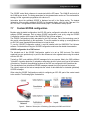
GOOSE configuration for a CMC test set
The intended use of the GOOSE Configuration module is to set up CMC test sets. The details
explained here are provided only to point out the differences to be regarded when using the module
with the ISIO 200.
Typically, a CMC is not publishing GOOSE messages for its own purpose. Mostly, the CMC publishes
"on behalf" of another protection or substation automation device to mimic some part of the behavior
of that device. Therefore, the publishing functions of the CMC are configured in the Simulations tab.
The data attributes from subscribed GOOSE messages operate the (virtual) inputs of the test set.
The (virtual) outputs of the test set manipulate the values of data attributes in simulated (published)
GOOSE messages.
When using the GOOSE Configuration module for configuring an ISIO 200, part of the context needs
to be reversed. The following figure illustrates this.
Figure 9:
Relation of Subscription & Publishing (Simulation) with CMC and ISIO 200
21
ISIO 200
GOOSE configuration for the ISIO 200
The GOOSE Configuration module will not be changed or adapted for the ISIO 200. Therefore, some
terms have different meanings when used with the ISIO 200.
Subscriptions are configured in the Subscriptions tab. The data attributes in the subscribed GOOSE
messages operate the binary outputs of the ISIO 200. Even though the hardware terminals offered for
mapping are labeled "Inputs" in the Subscriptions tab, the mappings actually refer to the outputs of the
ISIO 200. Only mappings to the "Bin. In." 1 to 8 (corresponding to the binary outputs 1 to 8 of the
ISIO 200) are valid and recognized by the ISIO 200.
The publications are configured in the Simulations tab. The data attributes in the published GOOSE
messages reflect the status of the binary inputs of the ISIO 200. Even though the hardware terminals
offered for mapping are labeled "Outputs" in the Simulations tab, the mappings actually refer to the
inputs of the ISIO 200. Only mappings to the "Bin. Out." 1 to 8 (corresponding to the binary inputs 1 to
8 of the ISIO 200) are valid and recognized by the ISIO 200. Up to eight GOOSE messages can be
set up for subscription and publication in the ISIO 200.
The ISIO 200 supports mapping to status value attributes (stVal) from the IEC 61850 common data
classes SPS (single point status) and DPS (double point status). The status value attributes in these
data classes are of the type boolean and bit string. Other data types are not supported for mapping.
When such a GOOSE configuration is set up, it must then be saved by using the function
Export Configuration … in the File menu. This file is then uploaded to the ISIO 200 (see
section 7.7.1 on page 22). After uploading, the GOOSE application restarts automatically and checks
if the custom GOOSE configuration can be applied. An invalid custom GOOSE configuration is not
loaded and the GOOSE application does not start.
7.7.1
Uploading a custom GOOSE configuration
This function is only available if the custom GOOSE configuration is selected (see section 7.4.1 on
page 19). A custom made GOOSE XML file (see section 7.7 on page 21) can be uploaded.
Even if one part of the GOOSE configuration (subscription or publication) is kept the same as the
default configuration, it has to be modeled in the GOOSE Configuration module as soon as a custom
configuration is used.
Use of information in SCL format
A configuration of the power utility automation system (and a related SCL file) is assumed to be
present prior to setting up a custom GOOSE configuration. The process corresponds to creating a CID
file for the ISIO 200. As of now, this process is to be done manually with the GOOSE Configuration
module.
22
Configuration and web interface
7.8
Download
The downloading of two different kinds of configuration files (SCL/ XML) is performed in the Download
page in the web interface.
The download of configuration data is only provided for the default GOOSE configuration and the
Download page is only accessible if the default configuration is selected.
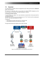
Terminology: Download / Upload
To avoid confusion, the usage of the terms download and upload within this document shall be
unambiguously declared.
The ISIO 200 is the server device and considered to be "up". The PC, which is used for configuring the
ISIO 200, is the client and considered to be "down".
Consequently,
• a file transfer from the ISIO 200 to the PC is a download, and
• a file transfer from the PC to the ISIO 200 is an upload.
The figure below illustrates this together with the usage of the data.
Figure 10: Downloading files from and uploading files to the ISIO 200
23
ISIO 200
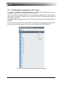
7.8.1
Downloading the configuration in SCL format
To perform a substation configuration according to the IEC 61850 engineering process, a
configuration file (SCL file) can be downloaded from the ISIO 200.
The SCL (ICD, IID) file provided reflects the current configuration of the ISIO 200. A minimal, generic
data model is contained, the binary I/Os are modeled as GGIOs. The following figure gives an
overview about the model.
The 8 binary inputs are modeled as Ind1 to Ind8. The 8 binary outputs are modeled as SPCSO1 to
SCPSO8.
This SCL file can be further used in an IEC 61850 engineering tool for creating the configuration for
the power utility automation system. The SCL file format is according to IEC 61850 Edition 1.
Figure 11: Binary I/Os modeled as GGIOs in the default configuration
24
Configuration and web interface
7.8.2
Downloading the configuration for usage with a CMC
To configure a CMC test set to communicate with an ISIO 200, a configuration file (GOOSE XML file)
can be downloaded from the ISIO 200.
To specify the (virtual) inputs and outputs of the CMC that the data in the GOOSE messages shall be
mapped to, the virtual input/output group and range of inputs within these groups have to be specified.
Selecting group 0 means that the "normal" (non-virtual, physical) inputs and outputs of the CMC are
used.
The GOOSE XML file can be imported into the GOOSE Configuration module to configure a CMC test
set to communicate with the ISIO 200.
The GOOSE published (simulated) by the CMC will be set up with the same identifiers as set in the
Subscription page of the ISIO 200. When this is properly set prior to downloading the configuration
from the ISIO 200, the file can be used without further adaptations. Otherwise, the configuration for the
CMC has to be edited in the GOOSE Configuration module.
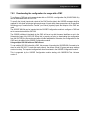
Using multiple ISIO 200 with one CMC test set
To use multiple ISIO 200 units with a CMC, this process of importing the GOOSE XML file needs to be
done for each ISIO 200. To make this work properly, the chosen virtual I/O group and range settings
must not overlap. The imported configurations are accumulated in the GOOSE Configuration module.
This is supported by the GOOSE Configuration module starting with OMICRON Test Universe
version 3.
25
ISIO 200
7.9
Hardware
7.9.1
Input settings
Threshold and hysteresis
The threshold voltage and the hysteresis can be set. The possible values are given in the technical
data (see section 10.3 on page 33).
The inputs become active when the input voltage is higher than the threshold voltage. The inputs
become inactive when the input voltage drops below the fallback voltage. The fallback voltage 𝑉𝐹𝑏 is
always lower than threshold voltage 𝑉𝑇ℎ and is calculated from the actual threshold voltage and the
hysteresis 𝐻 as follows:
𝐻
𝐻
�
= 𝑉𝑇ℎ �1 −
𝑉𝐹𝑏 = 𝑉𝑇ℎ − 𝑉𝑇ℎ
100 %
100 %
Example: when the threshold is set to 50 V and the hysteresis is set to 20 %, the inputs will fall back at
40 V:
20 %
� = 50 V ⋅ 0.8 = 40 V
𝑉𝐹𝑏 = 50 V �1 −
100 %
Deglitch and debounce time
The deglitch time and debounce time can be set for the binary inputs. For the possible values and the
effect of the parameters see the technical data (section 10.3 on page 33).
7.9.2
Input / output status
The I/O status display resembles the display on the front panel of the device (see section 3.1 on
page 11). It represents the current status of the binary I/Os of the ISIO 200.
Figure 12: I/O status display
7.9.3
Component information
Some information about the hardware components is displayed:
• CPU board revision
• FPGA firmware
• Binary output firmware
• Binary input firmware
This information may be requested by the technical support for analysis purposes.
26
Configuration and web interface
7.10
Time
The actual time of the clock in the ISIO 200 is used to set the time stamp in the headers of published
GOOSE messages with changed data (new status number). The following retransmissions have the
same time stamp. There is a slight delay (typical 20 to 100 µs) between setting the timestamp and the
actual publishing of the GOOSE message through the network interface.
Each connection established between the ISIO 200 and the browser on a PC has a time limit. When
the time is adjusted forward several hours it may happen that the actual time jumps beyond this limit.
This results in a termination of the connection and a new login is required.
7.10.1 Internal clock
The time is set manually. The clock relies solely on the free running internal oscillator of the processor
board in the ISIO 200. Consequently, the setting accuracy is poor and an additional time error will
accumulate over time.
The manual setting process may incur an offset of several seconds. The free running internal oscillator
has a frequency error of up to 50 ppm, which may result in an additional error of 4.32 seconds per
day.
Internal clock configuration
The current device time from the ISIO 200 is shown on the web interface. The time of the PC (host)
can be set to the device by clicking Get PC time and applying this.
7.10.2 NTP
The Network Time Protocol (NTP) is widely used and provides time synchronization for many IT
applications. The time servers can be in remote networks, since IP is used to exchange the
synchronization messages. Only IPv4 is supported by the ISIO 200.
The accuracy is good enough for many applications. The achievable accuracy depends heavily on the
performance of the network connection between the ISIO 200 and the time server(s), which cannot be
predicted. NTP provides no means for a formal specification. Typical synchronization errors are in the
range from 5 to 100 ms.
Up to three NTP servers can be specified as time sources. The servers can be either specified via an
IP address or an URL (if DNS is available).
Minpoll and Maxpoll specify the minimum and maximum polling interval. The value in the input field is
the exponent to 2 for the interval in seconds. For example, if a value of 5 entered, the ISIO 200 will
poll the NTP time server every 25 = 32 seconds. The possible values are from 4 to 17, resulting in an
interval between 16 and 131072 seconds.
7.10.3 PTP
The Precision Time Protocol (PTP) is an advanced method for accurate time synchronization. The
supported protocol versions are according to IEEE 1588-2008 and especially the "Power Profile"
IEEE C37.238-2011. The achievable synchronization error is below 1 µs when all involved
components support PTP accordingly.
The settings are the domain number, which is the same for all PTP clocks the ISIO 200 shall
synchronize with. Domain numbers are in the range from 0 to 127. The VLAN settings are used by the
power profile of PTP and determine how the IEEE 802.1Q VLAN tags of outgoing PTP messages are
set.
27
ISIO 200
7.11
System
7.11.1 Status
Some general information about the ISIO 200 system are shown (such as the serial number).
7.11.2 Maintenance
The Maintenance box offers some functionality to service the ISIO 200:
Reboot
This function reboots the ISIO 200. The current configuration is maintained.
Factory reset
This function resets the ISIO 200 to factory defaults. The current configuration gets lost.
After the reset, the following settings are restored:
•
•
•
•
•
•
•
Device finding via OMFIND is enabled, IP addressing mode is Auto-IP.
The default password is restored as printed on the nameplate of the device.
The GOOSE configuration is set to the default configuration with the serial number as IED
name.
The VLAN and retransmission parameters of the published GOOSE are reset to default
values.
The input threshold voltage, hysteresis, deglitch and debounce times are reset to defaults.
Be aware that the peer device for matched pairs cannot be restored by this process and has
to be set manually (see section "Matching pairs of ISIO 200" on page 20).
A new self-signed certificate is generated that is certified to the URL “ISIO-<SerialNumber>”.
System log
The log can be downloaded, for example for submitting it to the technical support for further analysis.
System snapshot
Click the Download button to download a system snapshot containing all configuration settings and
the log file. This file includes important information for the technical support in case of problems.
7.11.3 Firmware upgrade
Current version
Displays the firmware version currently installed on the ISIO 200.
Keep settings
If this check box is selected, the user specific configuration settings (Network/ GOOSE/ Hardware/
Time) are kept during a software update. Deselect the check box to automatically reset the device
configuration to the factory defaults after a software update.
Firmware upgrade
The firmware image on the ISIO 200 can be upgraded by pressing Upload and selecting the correct
firmware image file. The update process starts immediately.
28
Configuration and web interface
This may take up to 10 minutes. Do not disconnect the ISIO 200 or the computer during this process.
The ISIO 200 automatically restarts after the software update completed.
During the update, the LED S1 is off and LED S2 flashes red. When the update is finished, S2 goes
off and S1 lights green. See also section 3.1 on page 11.
If the software update process fails due to any reason, the ISIO 200 will enter a recovery mode on the
next power-up. In this mode, the device provides only a rudimentary web interface (similar to the
System page) just allowing for the upload of a software image.
Do not turn off the device during a firmware upgrade. The upgrade process takes several minutes!
7.11.4 Change password
At delivery, each ISIO 200 has an individual password that is printed on the nameplate.
Changing the password to one different from the one at delivery is an important cyber security
measure.
When a factory reset is performed, the password is also reset to the original password at delivery.
7.11.5 Licenses information
Open source license information is displayed to view copyright and license information regarding open
source products used in the ISIO 200 software.
Please refer to section "Open Source Software License Information" on page 31.
29
ISIO 200
8
Resetting the device
This section describes the operating procedures that can be performed directly on the ISIO 200 itself.
8.1
Reboot
To reboot the ISIO 200, perform the following steps:
1. Press the Reset button and release it immediately.
The device starts the reboot.
2. The S1 status LED goes off for approximately 1 second.
3. The S2 status LED lights up red during the boot process
4. After approximately 15 seconds, the S2 LED goes off and the S1 LED lights up green.
5. The device has successfully rebooted and is ready for operation.
A reboot of the ISIO 200 can also be initiated via the web interface (see section 7.11.2 on page 28).
8.2
Reset to factory defaults
To reset the ISIO 200 to factory defaults, perform the following steps:
1. Press the Reset button and keep it pressed.
2. The S1 status LED goes off.
3. After approximately 5 seconds, the S1 and S2 LEDs lights up.
Keep the button pressed and wait approximately 10 seconds until only the S2 LED lights up
red.
4. Release the Reset button.
5. After approximately 15 seconds, the S2 LED goes off and the S1 LED lights up green.
6. The device now has the factory default configuration settings and is successfully rebooted.
A reset to factory defaults of the ISIO 200 can be also initiated via the web interface. For more
information about that and for details about the status of the parameters after a reset see section
"Firmware upgrade" on page 28.
8.3
Recovery mode
Under normal circumstances it is not necessary to use this mode. This feature is only required if a
software update initiated via the web interface fails.
1. Press the Reset button and keep it pressed.
2. The S1 status LED goes off for approximately 5 seconds.
3. Release the Reset button as soon as the S1 (green) and S2 (red) LED lights up.
4. After approximately 30 seconds, the S1 LED flashes green to indicate the recovery mode.
5. Open the OMICRON Device Browser and right-click the ISIO 200 device. Set Network
Configuration … and select the Open Web Interface from the context menu. The device
provides a rudimentary web interface, allowing for an upload of a software image.
6. The firmware image on the ISIO 200 can be upgraded by pressing Upload and selecting the
correct firmware image file. The update process starts immediately and may take several
minutes. Do not disconnect the ISIO 200 or the computer during this process.
The ISIO 200 automatically restarts after the software has installed completely.
30
Open source software license information
9
Open source software license information
Parts of the ISIO 200 software are under OMICRON license, other parts are under open source
software licenses. For the complete licensing information on the open source software, please launch
the ISIO 200 web interface and click the License Information hyperlink on the system page.
The open source code is available on the Internet via www.omicron.at/opensource.
31
ISIO 200
10
Technical data
10.1
Power supply
10.1.1 Power over Ethernet
Power over Ethernet (PoE): ETH
PoE class
Power over Ethernet (PoE);
Class 2 powered device according to IEEE 802.3af
Power consumption
<5W
Ethernet type
10/100Base-TX
(10/100Mbit, twisted pair, auto-MDI/MDIX or auto-crossover)
Status indication
Green LED: physical link present
Yellow LED: traffic on interface
Connector
RJ45
10.1.2 Power input
External DC power input: POWER
Nominal DC input voltage
18 V ... 57 V
Power consumption
<5W
Connector
Terminal block
Maximum conductor cross section 1.5 mm²
Insulation
10.2
Product safety according to IEC 61010-1 and
IEC 60255-27 only achieved by using an external power
supply unit that complies with the SELV standard.
Insulation coordination
Insulation coordination
Protection class
Class II (double insulated)
Pollution degree
2
Insulation of functional groups
POWER and ETH on front
panel from each other
Working insulation
Clearance: > 2 mm
Creepage: > 2 mm
32
Technical data
10.3
Binary inputs
Binary inputs: BINARY IN 1-8
Number of binary inputs
8
Number of potential groups
2 (BINARY IN 1-4 and BINARY IN 5-8)
Rated input voltage
250 V
Sampling frequency
10 kHz
Time resolution
100 µs
Threshold
Range
Resolution
Error
Hysteresis
Range
Resolution
Deglitch time
Range
Resolution
Debounce time
Range
Resolution
10 ... 240 V; configurable via web interface;
default: 18 V
1V
< 5 % of reading + 250 mV offset
5 ... 50 % of threshold voltage; configurable via web interface;
default: 10 %
1%
100 µs ... 100 ms; configurable via web interface;
default: 0.5 ms
100 µs
0 ... 100 ms; configurable via web interface;
default: 1 ms
100 µs
Input impedance
148 kΩ
Measurement category
CAT II / 250 V (rms)
IEC 61010-2-030
Overvoltage category
III
IEC 60255-27
Connector
One terminal block for each potential group
Maximum conductor cross section 2.5 mm²
Insulation
Two reinforced insulated binary input groups
33
ISIO 200
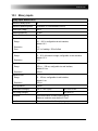
Deglitching input signals
In order to suppress short spurious pulses a deglitching algorithm could be configured. The deglitch
process results in an additional dead time and introduces a signal delay. In order to be detected as a
valid signal level, the level of an input signal must have a constant value at least during the deglitch
time. The figure below illustrates the deglitch function.
Figure 13: Signal curve, deglitching input signals
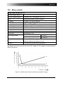
Debouncing input signals
For input signals with a bouncing characteristic, a debounce function can be configured. This means
that the first change of the input signal causes the debounced input signal to be changed and then be
kept on this signal value for the duration of the debounce time.
The debounce function is placed after the deglitch function described above and both are realized by
the firmware of the ISIO 200 and are calculated in real time.
The figure below illustrates the debounce function. On the right-hand side of the figure, the debounce
time is too short. As a result, the debounced signal rises to “high” once again, even while the input
signal is still bouncing and does not drop to low level until the expiry of another period Tdebounce.
Figure 14: Signal curve, debounce input signals
34
Technical data
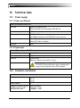
10.4
Binary outputs
Binary outputs: BINARY OUT 1-8
Number of binary outputs
8
Number of potential groups
2 (BINARY OUT 1-4 and BINARY OUT 5-8)
Type
Potential-free contacts; GOOSE controlled
AC loading
Vmax 250 V; Imax 8 A; Smax 2000 VA
DC loading
Vmax 250 V; Imax 8 A; Pmax 50 W (refer to load limit curve)
Carry capacity
5 A continuous @ 60 °C
Electrical lifetime
100 000 switching cycles at 230 V AC / 8 A and resistive load
Total make time
< 6 ms
Total break time
< 3 ms
Bounce time
approximately 0.5 ms
Overvoltage category
II
IEC 61010-1
III
IEC 60255-27
Connector
One terminal block for each potential group.
Maximum conductor cross section 2.5 mm²
Insulation
Two reinforced insulated binary output groups
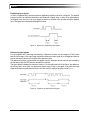
The diagram below shows the load limit curve for DC voltages. For AC voltages, a maximum power of
2000 VA is achieved.
Figure 15: Load limit curve for relays on the binary outputs with DC voltages
35
ISIO 200
10.5
Communication
10.5.1 Protocols
Protocols
Internet Protocol
IPv4; IETF RFC 791
Hypertext Transfer Protocol
HTTPS; IETF RFC 2818
GOOSE
IEC 61850-7; IEC 61850-8-1
Network Time Protocol (NTP)
NTPv4; IETF RFC 5906
Precision Time Protocol (PTP)
IEEE 1588-2008; IEEE C37.238-2011 (Power Profile)
Zeroconf
mDNS; DNS-SD and RFC 3927/IPv4LL (Avahi)
OMFIND
OMICRON device finding protocol (proprietary)
10.5.2 IEC 61850 GOOSE
GOOSE
Number of GOOSE messages
Maximum 8 published and 8 subscribed;
default: 1 published and 1 subscribed
Binary input state change to
publishing timing
850 µs (typical); < 1.1 ms for 99.99 % of all status changes
Received status change to
binary output activation timing
5.5 ms (typical); < 6.0 ms for 99.99 % of all status changes
Binary input to binary output
between two devices
6.1 ms (typical); < 6.5 ms for 99.99 % of all status changes
Retransmission interval
2 ms to 60 000 ms; initial value < final value;
default: 8 ms / 4096 ms
VLAN
IEEE 802.3Q tags. VLAN ID and priority selectable;
default: VLAN ID: 0 / priority: 4
Test conditions for GOOSE timing:
Publishing:
default GOOSE configuration, deglitch time 100 µs, wetting voltage 14 V,
threshold voltage 10 V, response on falling slope
Subscribing:
default GOOSE configuration, response on status change to contact closed,
all output contacts open, four contacts simultaneously closing
Binary IN to OUT: as for publishing and subscription, one switch between devices
36
Technical data
10.6
Time synchronization
Time synchronization
Internal clock
Accuracy
Network Time Protocol (NTP)
Accuracy
Typical achievable errors are in the range from 5 ms to 100 ms
Precision Time Protocol (PTP)
Accuracy
Maximum synchronization error 1 µs (IEEE C37.238)
10.7
Time source is the free running internal oscillator
No accuracy specifications
Environmental conditions
10.7.1 Climate
Climate
Ambient temperature for
operation
-20 °C ... +55 °C recommended
(+70 °C for 96 h)1
Storage and transportation
Cold Temperature
Dry Heat
-40 °C ... +85 °C
-40 °C for 96 h
+85 °C for 96 h
Maximum altitude
2000 m
Humidity
5 % ... 95 % relative humidity; no condensation
Climate
Damp Heat
IEC 60068-2-1
IEC 60068-2-2
6 cycles:
IEC 60068-2-30
12 h 25 °C + 12 h 55 °C; 95 % r.H.
10.7.2 Shock and vibration
Dynamics
Vibration
Response
Endurance
Tested according to IEC 60068-2-6 and IEC 60255-21-1 (Class 2)
frequency range 10 ... 150 Hz; 1 g; 1 sweep cycle per axis
frequency range 10 ... 150 Hz; 2 g; 20 sweep cycles per axis
Shock
Response
Withstand
Bump test
Tested according to IEC 60068-2-27 and IEC 60255-21-2 (Class 2)
10 g / 11 ms; half-sinusoid; 3 pulses in each direction
30 g / 11 ms; half-sinusoid; 3 pulses in each direction
20 g / 16 ms; half-sinusoid; 1000 pulses in each direction
1
Operation beyond the recommended temperature range will affect durability.
37
ISIO 200
10.8
Mechanical data
Mass, dimensions and protection
Mass
800 g
Dimensions W x H x D
170 mm x 50 mm x 125 mm (including DIN rail mounting clip)
Ingress Protection rating
(IP code)
IP40 according to IEC 60529
10.9
Cleaning
To clean the ISIO 200, use a cloth dampened with isopropanol alcohol or water. Prior to cleaning,
always unplug all connectors so that all hazardous life parts are disconnected and the device is turned
off.
10.10 Safety standards, Electromagnetic Compatibility, certificates
CE conformity, requirements
The product adheres to the specifications of the guidelines of the council of the
European Community for meeting the requirements of the member states regarding
the electromagnetic compatibility (EMC) Directive 2004/108/EC and the low voltage
Directive 2006/95/EC.
Electromagnetic Compatibility (EMC)
Emission
Europe
International
USA
ISM devices
Radiated: 30 MHz – 1 GHz
Conducted: 150 kHz – 30 MHz
EN 55011/22
IEC 60255-25
FCC, 47 CFR Part 15, Class A
Technology equipment
Radiated: 1 GHz – 6 GHz
Radiated: 1 GHz – 5 GHz
EN 55022, Class A
FCC, 47 CFR Part 15, Class A
Immunity
Europe
International
38
EN 61326-1; EN 60255-26; EN 61000-6-4
IEC 61326-1; IEC 60255-26; IEC 61000-6-4
FCC Subpart B of Part 15 Class A
EN 61326-1; IEC 60255-26; EN 61000-6-2
IEC 61326-1; IEC 60255-26; IEC 61000-6-2
Electro Static Discharge
Contact discharge: 6 kV
Air discharge: 8 kV
IEC 61000-4-2, Level 3
IEC 60255-22-2
Electromagnetic Fields
10 V/m, 80 % AM, 1 kHz Sinus
IEC 61000-4-3, Level 3
80 MHz – 6 GHz horizontal/vertical IEC 60255-22-3
Technical data
Electromagnetic Compatibility (EMC) – cont.
Burst
Binary I/O: 4 kV (peak)
Power: 2 kV (peak)
Communication: 2 kV (peak)
IEC 61000-4-4, Level 4
IEC 60255-22-4
Surge
Binary I/O: 4 kV (I/O-GND) / 2 kV (I/O-I/O) IEC 61000-4-5, Level 4
Power: 2 kV (I/O-GND) / 1 kV (I/O-I/O)
IEC 60255-22-5
Communication: 1 kV (I/O-GND)
Conducted Disturbance
0.15 MHz – 80 MHz, 10 V (unmod.)
80 % AM (1 kHz)
Binary I/O
Power
Communication
IEC 61000-4-6, Level 3
IEC 60255-22-6
Safety standards
Europe
EN 61010-1; EN 60255-27
EN 60950-1 (Insulation of ETH and SELV interfaces)
International
USA
Canada
IEC 61010-1; IEC 60255-27
UL 61010-1; UL 60255-27
CAN/CSA-C22.2 No 61010-1-04
Insulation test
Dielectric strength
Binary I/O: 4000 V, 1.2/50 µs
Power: 2000 V, 1.2/50 µs
Communication: 1500 V (DC)
IEC 61010-1
IEC 60255-27
39
ISIO 200
Glossary
CID
Configured IED Description
DHCP
Dynamic Host Configuration Protocol
DNS
Domain Name System
GCB
GOOSE Control Block
GOOSE
Generic Object Oriented Substation Event
EMC
Electromagnetic Compatibility
ESD
Electro Static Discharge
HTTPS
Hypertext Transfer Protocol Secure
ICD
IED Capability Description
IED
Intelligent Electronic Device
IID
Instantiated IED Description
IP
Internet Protocol
ISM devices
Industrial, Scientific and Medical devices
LD
Logical Device
MAC address
Media Access Control address
NTP
Network Time Protocol
ODB
OMICRON Device Browser
OMFIND
Protocol for finding devices on an Ethernet network
PoE
Power over Ethernet (IEEE 802.3at)
PTP
Precision Time Protocol (IEEE 1588, IEEE C27.238)
RTU
Remote Terminal Unit
SAS
Substation Automation System
SCL
Substation Configuration Language
SELV
Safety Extra Low Voltage
stVal
Status Value
TAL
Time allowed to live of a GOOSE message (timeAllowedtoLive)
URL
Uniform Resource Locator ("Internet address")
VLAN
Virtual Local Area Network
XML
Extensible Markup Language
40
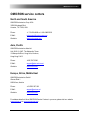
OMICRON service centers
OMICRON service centers
North and South America
OMICRON electronics Corp. USA
3550 Willowbend Blvd.
Houston, TX 77054, USA
Phone:
+1 713 830-4660 or 1 800 OMICRON
E-Mail:
[email protected]
Web site:
www.omicronusa.com
Asia, Pacific
OMICRON electronics Asia Ltd.
Unit 2812-19, 28/F, The Metropolis Tower
10 Metropolis Drive, Hung Hom, Kowloon,
Hong Kong S.A.R.
Phone:
+852 3767 5500
E-Mail:
[email protected]
Web site:
www.omicron.at
Europe, Africa, Middle East
OMICRON electronics GmbH
Oberes Ried 1
6833 Klaus, Austria
Phone:
+43 5523 507-333
E-Mail:
[email protected]
Web site:
www.omicron.at
For address details of other OMICRON Service Centers in your area, please visit our website
www.omicron.at or www.omicronusa.com.
41
ISIO 200
Index
A
E
Accessories ................................................... 9
Electromagnetic Compatibility ......................38
Environmental conditions .............................37
B
Binary inputs
Input / output status.................................26
Technical data...........................................33
Binary outputs
Input / output status.................................26
Technical data...........................................35
F
Firmware upgrade ........................................28
Front panel...................................................11
G
Glossary .......................................................40
C
GOOSE .........................................................19
Configuration for a CMC............................21
Custom GOOSE configuration ....................21
Certificates ...................................................38
Change password .........................................29
Default and custom configuration .............19
Cleaning .......................................................38
Publishing .................................................20
Restarting the GOOSE application ..............20
Climate ........................................................37
Communication ............................................36
Subscription..............................................20
Technical data...........................................36
Communication and access...........................16
Configuration and web interface ...................17
Uploading a custom GOOSE configuration .22
D
H
Deglitch and debounce time .........................26
Hardware......................................................26
Designated use.............................................. 7
Device discovery ...........................................18
Device overview ............................................11
I
Download .....................................................23
Input settings ...............................................26
SCL format ................................................24
Internal clock................................................27
DIN rail mounting .........................................13
CMC configuration ....................................25
42
Insulation coordination .................................32
Technical data...........................................37
Index
PTP...............................................................27
Technical data...........................................37
L
Licenses information ....................................29
M
Maintenance .................................................28
R
Rear panel ....................................................12
Resetting the device
Reboot ......................................................30
Recovery mode .........................................30
Factory reset .............................................28
Reboot ......................................................28
Matched pairs................................................ 8
Matching pairs of ISIO 200............................20
Mechanical data............................................38
Mounting......................................................13
Reset to factory defaults............................30
S
Safety instructions ......................................... 6
Safety standards ...........................................38
Scope of delivery ........................................... 8
N
Network .......................................................18
Network interface .........................................18
NTP ..............................................................27
Technical data...........................................37
Security certificate ........................................17
Shock and vibration ......................................37
Spare parts ...................................................10
Status LEDs S1 and S2 ..................................11
System .........................................................28
System log ...................................................28
O
System snapshot ..........................................28
OMICRON Device Browser .............................16
OMICRON service centers..............................41
Open source software license information .....31
P
T
Tabletop use ................................................14
Technical data ..............................................32
Threshold and Hysteresis..............................26
Power input ..................................................15
Time ............................................................27
Technical data...........................................37
Technical data...........................................32
Power over Ethernet......................................15
Technial data ............................................32
Power supply ................................................15
Technical data...........................................32
Protocols ......................................................36
W
Wall mount ...................................................14
Web interface ...............................................17
43