1
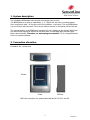
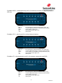
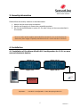
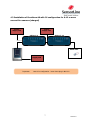
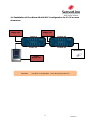
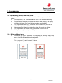
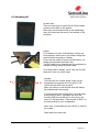
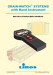
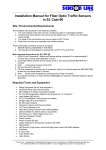
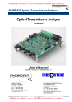
BOSSystem™
Bus Operating Sensor System
Intelligent Line Security System
Installation & User Manual
1
24/05/2011
Index
1. System description
Page 3
2. Connection allocation
Page 3-4
3. Security information
Page 5
4. Installation
4.1 EuroAlarm A8/SL12 - electronic devices
4.2 EuroAlarm A8/MP12 -live devices as mobile, MP3, GPS
4.3 EuroAlarm A8/C6 - live devices as cameras, DSLR
4.4 EuroAlarm A8/SL12 w. power for showcases
Page 5
Page 6
Page 7
Page 8
5. Programming
5.1 Programming Master- and User Cards
5.1.2 Delete all User Cards
Page 9
Page 9
6. Handling of EuroAlarm A8
6.1 Re-set button
6.2 Protection of power
6.3 Mounting A8
Page 10
Page 10
Page 11
7. Notes
Page 12
8. Contact
Page 12
2
24/05/2011
1. System description
This intelligent BOSSystem both secures and charges your phones.
The BOSSystem is so easy to understand, 1, 2, 3 steps and you have a working system.
Hour long service calls - to find the root of the problems - are history. The new BOSSystem
you can control with one card! This is all you need to service it, the system will do the rest.
The microprocessor in the BOSSystem measures for any changes to the system 2000 times
per second and charges all devices at the same time. A controlled delay prevents false
alarms and instability. Therefore, no shunt plugs are needed! This is a huge difference
from our previous systems.
2. Connection allocation
EuroAlarm A8 – central unit.
100mm
70mm
30.5mm
BUS: Bus connection for system terminals like MP12, SL12 and C6.
3
24/05/2011
EuroAlarm MP12 – charging/securing unit for live devices as mobile phones, MP3-players,
GPS, etc.
BUS 1/2:
BUS 2:
Power:
I/O:
1-12:
Bus connection for system terminals (MP12, SL12, C6)
Connect additional terminal or shunt plug if last terminal
Power Supply for MP12 (5V)
External Siren, Flash Light, CCTV
Sensor ports
EuroAlarm SL12 – securing unit for various electronic devices.
BUS 1/2:
BUS 2:
Power:
I/O:
1-12:
Bus connection for system terminals ( SL12, MP12, C6)
Connect additional terminal or shunt plug if last terminal
Power Supply for Lock Splitter, securing showcases (12V)
External Siren, Flash Light, CCTV
Sensor ports
EuroAlarm C6 – charging/securing unit for live cameras, camcorders and DSLR.
BUS 1/2:
BUS 2:
Power:
I/O:
1-6:
Bus connection for system terminals (C6, MP12, SL12)
Connect additional terminal or shunt plug if last terminal
Power Supply for C6 (12V)
External Siren, Flash Light, CCTV
Sensor ports
4
24/05/2011
3. Security information
Please follow the security measure as described below:
1. Always use the correct port connections.
2. Always use SensorLine or SensorLine compatible products.
3. Do not use the BOSSystem or parts of it for other things, as the ones subscribed in
this manual.
Never use other power supplies as described from SensorLine, due to the fact that the
SensorLine power supply is specially manufactured for the correct function of the ILSS.
4. Installation
4.1 Installation of EuroAlarm A8 with SL12 configuration for 12-24 or more
secured electronic devices
Object 1-6
Object 13-18
Object 7-12
Object 19-24
Shunt plug
Power
Supply 12V
Important:
Last SL12 in configuration - insert shunt plug in BUS 2!!!
5
24/05/2011
4.2 Installation of EuroAlarm A8 with MP12 configuration for 12-24 or
more secured live devices (charged)
Power
Supply 5V
Power
Supply 5V
Object 1-6
Object 13-18
Object 7-12
Object 19-24
Shunt plug
Power
Supply 12V
Important:
Important:
Last MP12 in configuration - insert shunt plug in BUS 2!!!
6
24/05/2011
4.3 Installation of EuroAlarm A8 with C6 configuration for 6-12 or more
secured live cameras (charged)
Power
Supply 12V
Power
Supply 12V
Object 1-6
Object 7-12
Shunt plug
Power
Supply 12V
Important:
Last C6 in configuration - insert shunt plug in BUS 2!!!
7
24/05/2011
4.4 Installation of EuroAlarm A8 with SL12 configuration for 12-24 or more
showcases
Power
Supply 12V
Power
Supply 12V
Lock 1-6
Lock 13-18
Lock 7-12
Lock 19-24
Shunt plug
Power
Supply 12V
Important:
Last SL12 in configuration - insert shunt plug in BUS 2!!!
8
24/05/2011
5. Programming
5.1 Programming Master- and User Cards
When the unit is new there are no Master- nor User Cards programmed in the
system.
1.
Connect power to A8. The number 8 will show in the display and running
beep will sound.
2.
Present Master Card (MC) in front of the antenna field (display) The display
will show the letter d for done. MC has now been programmed.
3.
To program User Cards (UC), present MC and the letter P for program will
show.
4.
Now present first UC and the letter d for done will show in the display.
5.
To program more UC, follow above routine. Note a max. of 30 UC.
6.
Now you are ready to set up the BOSSystem.
5.1.2 Delete all User Cards
1.
Present MC for approx. 10 seconds. You will get a fast “running” beeps, keep
presenting MC until the display shows the letter d for done.
All UC has now been deleted from the system.
To re-program UC, start from point 3 above.
9
24/05/2011
6. Handling of EuroAlarm A8
6.1 Re-set button
Press down the re-set button and you will get a
running beep.
The system is now back to factory parameters.
All MC and UC are deleted.
Remove power and back-up battery, wait up to 30
sec. before re-connecting power and you can
start to program new MC and UC.
Adjust volume for alarm.
6.2 Protection of power
The jumper on the top of the board has three pins
(two positions). It is needed that there is always a
jumper in place. The jumper position closest to the
edge, means that incoming power will be secured.
That is if you shut down power at night or remove
power from the system then the A8 will give alarm
un till back-up battery disconnect automatically after
approx. 2 min.
When the jumper is placed more to the center,
incoming power is no longer secured. That means if
you shut down power, no alarm will sound. Only the
BUS line is protected for a few minutes until back-up
battery disconnect automatically.
10
24/05/2011
6.3 Mounting A8
A8 back side:
There are two ways to mount the A8. Either cables
coming out the back or the bottom.
Either way screw the back side to the wall/display,
when first removing the screw in the bottom of the
enclosure.
Cables:
If no cables to be seen, and therefore coming out
from the back, make sure to put cables through the
back lid before mounting on display.
If you wish the cables to come out the bottom, you
simple remove/brake the bottom clip.
The BUS cable can be inserted near the enclosure so
coming out nicely along the power cable.
For drilling holes in display, use a 7mm drill for BUS
cable and 11mm for power cable.
A
B
Connect:
The first time you connect power it has not yet
recognized any terminals as SL12, MP12 or C6.
The A8 has two BUS lines, A and B.
When you receive a new A8 both lines will always
be protected with shunt plugs.
In last terminal in the configuration you must insert
a shunt plug in BUS 2, use spare one from A8.
Inserting BUS line into A8 can be a bit tricky, but
ones in, it will stay there. Then connect to BUS 1 on
the first terminal in your configuration.
Note: max. 10 terminals per line A and B, in total 20
per system.
Place battery as show here.
11
24/05/2011
7. Notes
8. Contact
12
24/05/2011