1
Ai
ESCAPE THE EVERYDAY
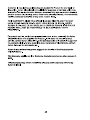
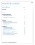
INSTALLATION AND OWNER'S MANUAL
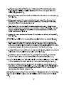
LANGHAM 48 IN X 35 IN X 75 IN COMPLETELY FRAMELESS SLIDING SHOWER ENCLOSURE
Co N
_ а
— N
— N
1 À
— N
\ N
L —— = — |
Shower Enclosure Model Number: SEN979.01
Please carefully read these instructions before you begin to install the products.
www.astonbath.com
03/14 Rev B
CA P/N:SEN979.01
Before you start
Thank you for purchasing your Aston shower enclosure. We hope that it will
provide you with years of satisfying use and enjoyment.
Please read this manual carefully because it contains information and instructions
about the proper installation of the unit. If you do not follow certain conditions of
installation and maintenance, your warranty may be affected.
1. Inspect boxes for shipping damage. If the product has been damaged, is
missing parts, or has a finishing defect, please contact our customer support
department within 5 business days of delivery date.
2. NOTE: You should consult your local building codes with questions on
installation compliance standards. Plumbing and building codes vary by location.
3. Before installation, inspect installation surfaces or level and have to the
strength to support the heavy weight of this shower enclosure assembly. This
Shower Enclosure should only be installed using the connection point to the studs
or to pre-installed 2x6 wood reinforcements behind the wall.
4. This Shower Enclosures assembly is very heavy and requires professional
installation.
Aston Shower enclosure's feature:
eo Tempered Safety Glass
e High quality hardware
WARNING: The Aston Shower enclosure is designed to be used with tiled
walls. If you are using a pre-made Acrylic/ABS/FRP shower stall that will be
thicker than average plus tile, then you must consider the offset of the
pre-made panel thickness. If applicable, the shower tray has 1/4" of
tolerance for the oversized wall thickness.
Certifications:
All Aston Shower enclosures are 3rd party tested to meet the following US,
Canadian and International Standards:
oe CPSC 16 CFR1201 Il / ANSI 297.1 - 2009 Class A
e CSA B45 Series - 02
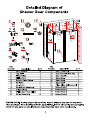
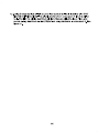
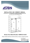
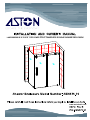
Detailed Diagram of
Shower Door Components
В: © Isa 45
NIE
e e NR
KO 0
q |" 11 N
13 В 6/7 | N
| 14 N
pore — N
15 N
E AL
de || N
16 O N
NL
Key Key
Number Description QTY Number Description QTY
1 Door Stopper 2 12 Door Threshold 1
2 Top Rail 1 13 Door Threshold End Cap 2
3 Fixed Glass 1 14 Door Handle 1
4 Sliding Door 1 15 Door Seal 1
5 Return Glass Panel 1 16 Door Seal 1
6 Rail End 1 17 Door Seal 1
7 Wall Mount 1 18 Fixed Glass Bolt Assembly 2
8 Rail Mount Assembly 1 19 Screw Pack 1 1
9 Glass Clamp 4 20 Screw Pack 2 1
10 Sliding Door Track Divider 1 21 Screw Pack 3 1
11 Roller Assembly 4 22 Screw Pack 4 1
PLEASE NOTE: During unpacking carefully inspect all parts and use the exploded
view drawing to identify all parts in the parts listing. Before discarding the packaging
check for any parts or small hardware bags that may have been overlooked.
2
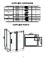
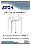
SUPPLIED HARDWARE
/SCREW PACK | M4x40 3 N
(1) Anchor 3
M4x40 1
SCREW PACK
(2) Anchor 2
M5x40 1
SCREW PACK M4x40 2
(3) Anchor 2
SCREW PACK M4x40 2
NN (4) Anchor 2
SUPPLIED PARTS
NN 1
Yo | 48/5" |
1 A"
= aN
G6—— ©
| 2.
LO
CN
07
N
О’
— — AQ"
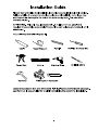
Installation Guide
Please read and follow the installation instructions and guidelines in this section.
Failure to follow the recommended instructions and installation techniques may
lead to possible damage to the unit or the surrounding area. This can affect
warranty claims.
ATTENTION: This unit requires assembly. A minimum of two people are
required for assembly, as several of the sections can be large and unstable until
assembled.
You will need the following tools:
>> > = “=
Caulk Tape Measure Pencil Phillips Screwdriver
) >
Ю > N —& | N
10 >
Caulk Gun Level Electric Drill Drill bit (2974")
On )
Hammer Miter saw or Hacksaw
Locate the accessory box and remove the individual screw and hardware packages.
Lay them out in seguential order to aid in completing the rest of the installation.
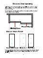
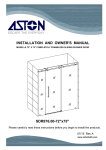
Reverse Door opening
This shower door can be assembled so that the sliding door opens from Left to
Right, or Right to Left. The drawings below illustrate the shower door opening
from Left to Right.
Note the location of the fixed glass panel and return glass panel for the shower
door opening from Left to Right.
И ИИ ИИ,
N NNNNNN NN
Fixed Glass
Sliding Door
Return Glass Panel
| 9 n
Return Glass Panel Sliding Door Fixed Glass
If your project requires the door to open from the opposite direction, flip the
top rail installation so that the Return Glass Panel (5) is on the right when
installed.
Measure the distance
TN
SE
LT
— SUR
A
— = AS SC ~~
Da + | DH HE
AS > CT P= —#
<— E TT
AT a — =
UT LAN —#
HT LT — SH
— AIT NC HE Ds
| TTT >
| Eo |
uN Ss
<< SL © SSL
rm
>
о
29 En
Fa
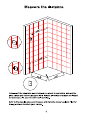
Install all of the wall material or materials you intend to use before installing the
glass clamps and return glass panel, this includes all moisture resistant wall board
or rock board, tile, stone or other wall covering.
Refer to the drawing above and measure and mark the shower wall and floor for
drilling locations to attach glass clamps.
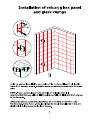
Installation of return glass panel
and glass clamps
\\\\\\\ \
п \ ААА \ \\А\\
\\\ \ \ \ \ \ \ \
[ JSS)
[f SSS JS
1 /// ////7///
\
/
\
Using the appropriate drill bit for your wall and floor surface drill each hole location
with a 5/16” diameter drill bit. Install the plastic wall anchors provided into the drilled
holes
NOTE: If your surface is prone to cracking or chipping then it is
recommended that you pilot drill first using a smaller drill bit, and then step up
to the final size.
Using screw pack (1) attach the glass clamps (9) to wall and shower floor using
M4x40 screws. Screw Pack 1. The glass clamps (9) should be positioned so that the
single hole is facing toward the inside of shower.
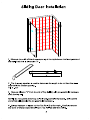
Sliding Door Installation
|
|
gS NN ZO
LN LS
E |
1. Measure the width of the shower opening at the top between the fixed glass and
the wall. Note this is dimension "X".
)
lo —
A
hs
С
<
2. The following equation is used to determine the length to be cut from the rail in
order to fit the shower opening.
У = Х - 1/2”
3. Measure distance "Y" from the end of Top Rail (2) with pre-assembled hardware
mark the top rail.
NOTE: Do not cut the end of top rail with pre-assembled hardware. Only cut the
end of top rail opposite the pre-assembled hardware.
4. Using a hacksaw or jigsaw cut the Top Rail (2) at the mark. Carefully remove
any burrs or sharp edges remaining on Top Rail (2) after the cutting.
8
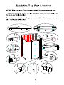
Mark the Top Rail Location
ATTENTION: A minimum of two people are required for the next assembly steps.
Pre-assembly the top rail (2) onto the fixed glass (3) to locate the mounting points on
the wall to your desired location.
Painters tape or masking tape in the general location of the of the final installation will
aid in marking the wall and floor.
ААА оу
Г
pd
Slide door stopper (1) onto end of top rail (2) See figure 1. The bumpers on door
stopper (1) should be positioned on the top of top rail for final installation. Note:
One door stopper comes pre-assembled on top rail between fixed glass bolt
assembly. See figure 1.
Position the top rail (2) and fixed glass (3) as shown in figure 2 and connect fixed
glass (3) to top rail (2) following the assembly sequence shown in figure 2. Note
in figure 2, one door stopper (1) should be positioned between mounting holes in
top rail (2) before connecting top rail to fixed glass.
NOTE: TOP RAIL IS ATTACHED TO THE INSIDE OF FIXED GLASS.
3.
Slide the rail end assembly (6) onto end of top rail (2) to be connected shower
wall. Loosely tighten the rail end assembly (6) into place on top rail (2) making
sure the rail end assembly is fully engaged on top rail. See figure 3.
Locate the rail mount assembly (8) and remove the stainless steel fitting and
glass connector parts from the metal sleeve. Loosen the set screws in metal
sleeve and slide onto end of top rail (2) making sure the end of sleeve which is
threaded is facing toward end of top rail. Loosely tighten set screws in metal
sleeve to secure. See figure 4-1
Next assemble the stainless steel fitting and glass connector parts to top hole in
return glass panel (5), following the assembly sequence shown in 4-2. The
stainless steel fitting should be positioned to the inside of return glass panel (5)
when complete.
Position the top rail / fixed glass assembly into place in your shower. Loosen the
set screws in rail mount (8) next to glass panel (5). Next connect rail mount (8)
to stainless steel fitting by threading rail mount and stainless steel fitting together
and tighten into place. Tighten set screws in rail mount to secure to top rail (2).
See figure 5.
NOTE: THE TOP RAIL ATTACHED TO FIXED GLASS SHOULD BE POSITIONED
TO INSIDE OF SHOWER.
6.
Using a level, verify the top rail (2) is horizontal and the fixed glass (3) is plumb,
mark the rail end (6) location on wall. See figure 6-2
Remove pre-installed screw from pre-assembled glass clamp (9). Position the side
of the glass clamp (9) with floor mounting hole on the floor and align with large
hole opening on bottom of fixed glass (3). Mark the mounting hole of glass clamp
(9) at this position. See figure 7
10
NOTE: If your surface is prone to cracking or chipping then it is recommended
that you pilot drill first using a smaller drill bit, and then step up to the final size.
8. Using the appropriate drill bit for your floor surface drill hole locations with 5/16"
diameter drill bit and install the plastic anchor from screw pack 2 into the drilled
hole for glass clamp.
11
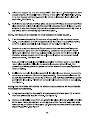
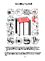
Installing Top Rail
4 Note: The set 3
screw locations in
rail end are not
centered. Assemble
per drawing.
1. Loosen set screws in rail end (6) and remove from top rail (2). See figure 1-1.
Next remove wall mount (7) from rail end (6). Position wall mount (7) onto
marked location on shower wall and mark pilot hole drilling location. See figure
1-2
NOTE: If your surface is prone to cracking or chipping then it is recommended
that you pilot drill first using a smaller drill bit, and then step up to the final
size.
12
Using the appropriate drill bit for your wall surface drill the hole location with a
5/16" diameter drill bit. Install the plastic anchors from screw pack 2 into the
drilled hole. See figure 2.
Attach the wall mount (7) to shower wall using M5 x 40 screw from screw pack 2.
See figure 3.
Position glass clamp (9) on floor and attach to floor using M4 x 40 screw from
screw pack 2. The glass clamp should be positioned so the single hole is facing
toward the inside of shower. See figure 8.
Slide rail end (6) onto top rail (2) and loosely tighten into place. Note: The set
screws in rail end are not centered, and one end of rail end is threaded. The rail
end (6) should be installed on top rail (2) so that threaded end of rail end (6) is
facing outward. See figure 4.
Loosen set screws in rail mount receiver (8) and slide onto left end of top rail (2).
See figure 5.
ATTENTION: A minimum of two people are required for the next assembly steps.
7.
Position top rail / fixed glass assembly into place in your shower opening. Next
align rail mount reciever (8) with brass fitting on inside of return glass panel (5),
and secure by tightening the rail mount receiver to brass fitting. Tighten set screws
in rail mount receiver (8) to secure to top rail (2) See figure 5 and 7-2.
Thread rail end (6) onto wall mount (7) and securely tighten. Tighten set screws in
rail end (6) to secure rail end to top rail (2). See figure 7-2.
Install glass clamp (9) to fixed glass (3). See figure 8 for details. Smooth flat
surface of glass clamp (9) should be installed on outside of fixed glass (3).
10. Insure plastic sliding door glide is in place in underside of sliding door track divider
(10) and positioned to proper location for 10mm glass thickness. See figure 9.
11. Position the sliding door track divider (10) into position as seen in figure 10 and
mark the 2 shower base hole positions. Note: In drawing 10 the hole locations
for attaching sliding door track divider should be 1 13/16" from edge of
fixed glass. See details in figure 10.
NOTE: If your surface is prone to cracking or chipping then it is recommended
that you pilot drill first using a smaller drill bit, and then step up to the final
size.
13
12. Using the appropriate drill bit for your floor surface drill hole locations with 5/16"
diameter drill bit and install the plastic anchors from screw pack 3 into the drilled
hole. Position the sliding door track divider (10) over drilled holes on floor, and
secure sliding door track divider (10) to floor using hardware in screw pack 3. See
figure 11.
14
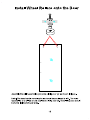
Install Wheel Rollers onto the Door
Assemble the roller assemblies (11) onto sliding door (4) as shown in figure.
Note: The door handle mounting holes should be positioned to left. The roller
assemblies (11) will be on the outside of sliding door (4). The sliding door should
be to the inside of shower area.
15
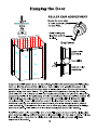
Hanging the Door
ROLLER CAM ADJUSTMENT
Rotate the outer edge
of roller assembly using
the small hex,
while holding the
large hex wrench
in place.
End View
| TNT
_ | upper roller
_ i assembly
| 1 _ 0) top rail (2)
| | oN ” = > |
— | | I bottom roller
I | assembly
)
\|- T ‘| LL
Suspend the sliding door (4) on the top rail (2). Position the bottom edge of sliding glass
door (4) into the groove of the sliding door track divider (10). Adjust the upper roller
assemblies (11) to insure the bottom edge of sliding glass door (4) does not touch the
bottom sliding door track divider (10). See roller cam adjustment drawing for details.
(The rollers for this unit have a built in cam adjustment to adjust the plumb of sliding door.
Locate the small hole in outside edge of roller assembly and insert a small hex wrench into
hole opening. Next using the hex wrench for roller assembly slightly loosen the roller
wheel assembly. Now holding the hex wrench in place rotate the outer edge of roller
assembly using the small hex wrench inserted into small hole opening in outer edge of
roller assembly. This will move the roller cam to offset any minor adjustments for sliding
door out of plumb. All 4 rollers on this unit can be adjusted as describe above).
Install the bottom roller assemblies (11) on the sliding door (4) to secure the sliding glass
door (4) to top rail (2). Adjust the bottom roller assemblies (11) to a gap of 1/32". This gap
Is a starting gap, check that the sliding door rolls smoothly along the top rail. Make
adjustments if needed. 16
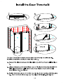
Install the Door Threshold
The Door Threshold is used to prevent water from seeping out while bathing.
Install the threshold according to these instructions.
1. Measure the distance between the fixed glass (3) and the shower wall. See figure
1.
2. Using a hacksaw cut the threshold bar (12) to fit distance measured between the
fixed glass and shower wall. Remove any sharp edges or burrs after cutting
threshold bar (12). See figure 2
3. Position the threshold bar (12) to floor by aligning in door opening with fixed glass
(3). Mark the threshold end cap (13) mounting hole locations. See figure 3
17
NOTE: If your surface is prone to cracking or chipping then it is recommended
that you pilot drill first using a smaller drill bit, and then step up to the final size.
4. Using the appropriate drill bit for your floor surface drill the hole locations with a
5/16" diameter drill bit. Install the plastic anchors from Screw pack 4 into the drilled
holes. Repeat for the other side. See figure 4
5. Add a small amount of silicone sealant to bottom of threshold bar assembly place
into position. See figure 5
6. Using the hardware from screw pack 4 install the threshold bar assembly.
Install the decorative screw plug covers into threshold end caps (12). See figure 6
18
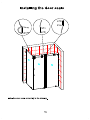
Installing the door seals
HED
| ail
| N
| N
1 | D
| ° N
N AS
NO
Install the door seals according to the drawing.
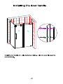
Installing the door handle
TT
— 1 | \
a 1
| о AS J00-— 6-0
AS
в | N
I N. DO | — В
\ N _
HN
Install the door handle (14) using hardware provided. Follow the assembly sequence
seen in drawing.
20
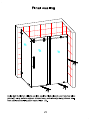
Final sealing
|
|
|
7
|
и
i /
e
¿a
24
E
До
Using Bath & Kitchen silicone sealant, seal the fixed glass (3) and returned glass
panel (5) along bottom edge on shower base, and side edge along shower wall.
Next seal around sliding door track divider (10).
21
Care and Maintenance
As with any other luxury item, maintenance and care are critical to the long lasting
quality and enjoyment of your shower door and tray. The proper care and
maintenance outlined in this section are necessary to ensure the longevity of the
unit. Damage caused by not following the care and maintenance guidelines in this
section is not covered under the manufacturer's warranty.
The glass doors and panels can be cleaned using any commercially available
glass cleaner.
We recommend that you clean the glass daily and squeegee the glass with a
silicone or rubber squeegee after each use to help prevent water spots.
22
Warranty
PLEASE READ THESE WARRANTY TERMS AND CONDITIONS CAREFULLY
BEFORE USING YOUR ASTON GLOBAL BATHROOM PRODUCT. BY USING THE
PRODUCT, YOU ARE CONSENTING TO BE BOUND BY THE FOLLOWING
WARRANTY TERMS AND CONDITIONS.
SHOWER DOOR/SHOWER TRAY
Aston Global Inc. Parts-Only Limited Warranty 5 years
Aston Global, Inc. ("Aston Global”) warrants to the original retail purchaser (“Owner”) of
any Shower Door/Tray product (“Product”), at the original installation site, for a period of
Five (5) years from date of purchase (whether directly from Aston Global or an authorized
reseller) that the Product manufactured by Aston Global is free from manufacturing
defects in materials and workmanship, when used under normal conditions and when
such Product has not been modified or changed in any manner after leaving Aston
Global's warehouse or plant. If any Product manufactured by Aston Global is found to
have manufacturing defects in materials or workmanship, such Product will be repaired or
replaced by Aston Global. This warranty applies only against defects discovered within
the warranty period and extends only to the original purchaser of the Product. Parts
repaired or replaced under the terms of this Warranty will be warranted for the remainder
of the original warranty period only.
Proof of purchase is required to exercise this Warranty. Aston Global may, at its option,
examine and inspect the alleged defective Product, and Aston Global may request that
parts be returned to Aston Global at Owner's expense for factory inspection. The
determination as to whether Product shall be replaced, or in the alternative, repaired, shall
be made solely by Aston Global. If a Product is determined to be covered by the above
Warranty, Aston Global will ship the replacement part(s) to Customer by either ground
shipping or US postal service. Increased costs for expedited delivery, if requested by
Customer, are the responsibility of Customer. Parts not currently in stock may require up
to a 6 week delivery time after placement of order.
The above warranty is subject to the following conditions: (1) the Product must be
installed in a single family dwelling unit where the original purchaser of the Product
resides; and (2) the Product must be maintained as described in the owner's
manual supplied with the Product.
For glass and acrylic panels, the customer must (a) open and inspect the Product
upon delivery (without releasing the delivery driver until visual verification that the
Product arrived in a good and acceptable condition); and (b) clearly notate damage
on the delivery acknowledgment receipt. Failure to do so, and any damage
discovered to glass or acrylic panel after delivery, will be repaired or replaced at
the sole discretion of Aston Global.
23
THIS WARRANTY DOES NOT COVER:
1. Product installed in buildings other than single family dwelling units.
2. Product installed outdoors or any other non-standard bathroom location.
3. Component parts not manufactured by Aston Global.
4. Workmanship of any installer of Aston Global Product. This warranty does not assume
any liability of any nature for unsatisfactory performance caused by improper installation,
or any damages to property resulting from improper installation or use of the Products,
including but not limited to flooring, subfloor, tile, walls, sheet rock, concrete board, paint,
plumbing fixtures and ceilings.
5. Labor costs incurred in the removal, disassembly, reassembly, or installation of the
Product(s), including replacement Products issued under the Warranty, or costs for
transportation to Aston Global, and any other materials necessary to return Product to
Aston Global.
6. Any Product that has been damaged as a result of being improperly serviced or
operated, including, but not limited to, the following: operated with insufficient water;
allowed to freeze; subjected to flood conditions; operated with water conditions or
additives which cause unusual deposits or corrosion in or on the Product, or subject to
any other abuse or negligence.
7. Any Product that has been damaged as a result of natural disasters, including, but not
limited to, lightning, fire, earthquake, hurricanes, tornadoes or floods.
8. Product used for any purpose other than residential bathroom usage.
LEGAL DISCLAIMERS
ALL IMPLIED WARRANTIES, INCLUDING WARRANTIES OF MERCHANTABILITY
AND FITNESS FOR A PARTICULAR PURPOSE, ARE HEREBY DISCLAIMED IN
THEIR ENTIRETY WITH RESPECT TO ALL PURCHASERS OR OWNERS. FAILURE
TO RETURN THE WARRANTY CARD SHALL HAVE NO EFFECT ON THE
DISCLAIMER OF THESE IMPLIED WARRANTIES. ALL EXPRESS WARRANTIES
SHALL BE LIMITED TO THE DURATION OF THIS EXPRESS LIMITED WARRANTY
AND EXCLUDE ANY LIABILITY FOR CONSEQUENTIAL OR INCIDENTAL DAMAGES
RESULTING FROM THE BREACH OF ANY EXPRESS WARRANTY. Some states do
not allow the exclusion or limitation of incidental or consequential damages, so the above
limitations or exclusions may not apply. No dealer, distributor, service company or other
party is authorized to change, modify or extend the terms of this warranty in any manner
whatsoever.
Aston Global and it representatives shall not be liable for any injury, loss, cost or other
damages, whether incidental or consequential, arising out of any defect covered by this
Warranty including and without limitation, loss of use of the Product and cost for removal
of defective Product, even if Aston Global has been advised of the possibility of such
damage. The liability of Aston Global under this Warranty, if any, shall not exceed the
original amount paid for the Product covered by the Warranty. Coverage under this
Warranty shall commence as of the original date of purchase and the duration of such
coverage shall not extend for any reason whatsoever beyond the stated time period. The
24
Customer is required to provide adequate access the Product for any repair or
inspection. Aston Global shall not be liable for expenses or damage which may
include but are limited to water damage, removal of any and all common building
product such as tile, flooring, wood, sheet rock, plumbing fixtures, concrete board,
vanities, bathtubs and toilets or any other custom items.
THIS WARRANTY GIVES YOU SPECIFIC LEGAL RIGHTS AND YOU MAY
HAVE OTHER RIGHTS WHICH VARY FROM STATE TO STATE. ASTON
GLOBAL'S FAILURE TO ENFORCE ANY TERMS OR CONDITIONS STATED
HEREIN SHALL NOT BE CONSTRUED TO BE A WAIVER OF SUCH
PROVISION.
For prompt service, notify the original installer who, in turn, will notify the Aston
Global distributor who supplied the Product. If this does not result in prompt
service, contact Aston Global, Inc. at the address below with details in support of
the warranty claim. For any questions about coverage of this Warranty, contact
Aston Global at the address below.
Aston Global offers free phone support for the life of the Product to the
original Owner.
The Warranty applies only to Products manufactured on or after January 1,
2012.
This Warranty may not be combined with any other warranty offered by
Aston Global.
25
ANIGN EE
Bringing Serenity to Your Hone and Tranquility to Your Every Day Life
Customer Service
877-424-9699
Aston Global Inc
10480 Brockwood Rd
Dallas, TX 75238
If further assistance is needed, or you
have a question, please visit our web
site at:
www.astonbath.com