1
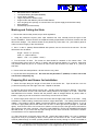
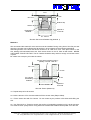
Installation Manual for Fiber Optic Traffic Sensors
in SL Cast-90
Site / Environmental Requirements
The installation site should be in the following condition:
1. The road surface in the area must be a continuous plane in undamaged condition.
2. Existing track deformations (ruts) should not be deeper than ½“ (15mm) over the whole
sensor length.
3. The slope of the road surface can have a height of 3/8“ (10mm).
4. Slots must not cross over separate road surface sections.
The environmental conditions should be as follows:
1. NEVER INSTALL SENSORS IN THE RAIN.
2. The ideal ground temperature is between 50° to 90°F (10°C and 35°C)
Main Important Instructions for SL CAST-90:
1. ALWAYS stir Component 1 (Black stuff) before adding component 2 for approximately 2
minutes with a mixing spiral (Diameter: 6-8 cm).
2. Avoid high RPM to prevent air from being mixed in. We recommend 600-800 RPM for 2
minutes.
3. Note:
Lower speed requires more time!
4. Stir all of the stuff in the can!
5. Fill all of component 2 into the can of component 1and stir it with low speed too (600-800 RPM)
at least for one minute better 2 minutes.
6. Note:
Proper and homogeneous mixing ensures curing of all parts!
7. SL Cast-90 is sensitive to water therefore dried slots are required. Otherwise adhesion will be
disturbed!
Required Tools and Equipment
•
•
•
•
•
•
•
•
•
•
•
•
•
•
•
•
•
•
•
•
•
•
•
Safety Equipment (as per local regulation)
Sensorline Fiber Optic Axle Sensor(s)
MA-100/MA-110 Optical Transmitter Analyzer
SL Cast 90 Encapsulation Material (1kg of grout per 1m of sensor)*
Loop sealant (NO hot tar)
PVC or Polyethylene Tubing (home run cables)
Straight edge (8’ [2.5m] minimum)
20’ (6m) tape measure
Pavement Crayons and Pavement Paint
1/8” (3mm) diameter cord
35hp Wet-Cutting Pavement Saw (self-propelled)
Diamond Blade ¾” (20mm) wide (or equivalent)
3/8” (9mm) or ¼” (6mm) blade (home run)
Hammer & Masonry Chisels
Power Washer
Water (at least 250 gal)
Larger Capacity Air Compressor (at least 150 CFM)
Street Broom
LED Source or light power source with light power meter with SMA adapters
Volt Meter
2” Duct Tape
Foam Backer Rod
Latex Gloves
Sensor Line - Gesellschaft für optoelektronische Sensoren mbH, In der Scherau 1, 86529 Schrobenhausen/ Germany
Tel. +49 (0) 8252 8943 0, Fax +49 (0) 8252 8943 11, Email: [email protected], HP: www.sensorline.de
•
•
•
•
•
•
•
•
Electrical Power or Generator
Low Speed Mixing Drill (600-800RPM)
2 each Mixing Paddles
Large Putty Knife or Small Trowel
Angle Grinder with Masonry Wheel or Belt Sander
20 or 22 gauge wire (enough to connect MA-110 to power supply and interface board)
Wire strippers
Oscilloscope (recommended)
Marking and Cutting the Slots
1. Ensure the road is safely closed, as per local regulations.
2. Using the pavement crayons, paint, tape measure and cord, carefully mark the layout of the
sensor installation. Ensure sensors are emplaced exactly perpendicular to the flow of traffic and that
all lines are straight. The sensors should not be placed any closer than 4“-6“ (100-150mm) apart in
order to ensure integrity of the road surface.
3. Use 1" or the ¾“ (20mm) Diamond Blade with spacers, wet cut the slot for the sensors The slot
dimensions are as follows:
length = sensor + 2“ (50 mm)
width = 1“ (23mm-26mm)
depth = 1 1/8“ –1 ¼“ (28mm –31mm)
4. Cut the home run slots. The home run slots should be centered on the sensor slots. The
minimum width of the home run slot is ¼“ (6mm) and the minimum depth is ½“ (12mm). More than
one passive cable may be run in a home run slot, but the slot should be cut wider at ½“ (12mm) in
this case
5. Power wash and sweep all slots. All slots must be very clean.
6. Dry all slots with compressed air. All slots and the pavement 1’ (300mm) on either side of the
slot must be completely dry.
Preparing Slot and Sensor for Installation
7. Place duct tape along the length of both sides of the sensor slot. Tape should be 1/16“-1/8“
(1.5mm-3mm) away from the edge of the slot. Repeat for all slots.
8. Remove the Fiber Optic Sensor from the box. Visually check the sensor for damage. The sensor
should not be broken or bent, and outer black coating should not be ripped, cut or torn. Check the
lead attachment for breaks. Ensure that the passive cable is straight without any kinks, tears or
breaks. Lightly tug at end connectors to ensure they are not loose or broken.
9. Connect light power source to one end connector and the light power meter to the other. Using
the 650nm or 780nm setting, measure the amount of light attenuation. The reading should be below
30dBm. If the reading is above 30dBm consult with Sensor Line before installing sensors. If you do
not have a light power source and meter use an LED or other light source (sunlight or overhead
lights). Connect the LED to one connector or hold the connector up the the light source and look for
light coming out the other connector. DO NOT LOOK DIRECTLY INTO THE CONNECTOR WHILE
AN LED IS ON. If you cannot see any light coming from the other connector, the sensor is broken.
Consult Sensor Line for replacement/repair.
10. Place the sensor on the tape next to the slot. Unwind the passive cable. Lay it out in meanders
longer than 10 ft (3 m) avoiding to twist it. Then place it in the home run slot. If the passive cable
must be pulled through a conduit, pull the passive cable all the way through to the lane controller or
Sensor Line - Gesellschaft für optoelektronische Sensoren mbH, In der Scherau 1, 86529 Schrobenhausen/ Germany
Tel. +49 (0) 8252 8943 0, Fax +49 (0) 8252 8943 11, Email: [email protected], HP: www.sensorline.de
traffic box where the MA-110 is to be emplaced. Pull cable slowly and steadily through the conduit.
DO NOT JERK CABLE THROUGH CONDUIT AND DO NOT PULL HARD THE PASSIVE CABLE.
DO NOT PULL THE PASSIVE CABLE BY THE END CONNECTORS. ATTACH SNAKE OR ROPE
TO PASSIVE CABLE AT LEAST 3“ FROM END CONNECTORS. Be extremely careful when pulling
the cable through and around 90° bends or turns. Minimum bend radius for the conduit is 5/8“
(15mm).
11. Once the passive cable is pulled to the lane controller/traffic box repeat step #9. If the sensor
now fails, it was damaged while being pulled through conduit/home run slot. Replace end connectors
and repeat (see instruction sheet for replacing end connectors). If it still fails, do not install sensor.
12. Place sensor in slot to ensure length and fit is correct. The sensor should have space at least
1/5“ (5mm) between it and the slot wall on both sides.
13. Remove sensor from slot and place on tape. Remove the rubber sensor clips from bag and fix
the clips on the sensor in 5“-7“ (150mm-180mm) intervals.
Installing and Encapsulating the Sensor
14. Place passive cable inside home run slot and seal slot with foam backer rod to keep SL Cast 90
from seeping out of the sensor slot into the home run slot.
15. Using a low speed mixing drill (600-800rpm) with a mixing paddle, premix component 1 (black) of
the SL Cast 90 for two minutes. Be sure to keep air bubbles out of component while mixing.
16. Add all of component 2 (clear hardener) into can of component 1. Mix for at least 1 minute with
low speed drill (600-800rpm) with a mixing paddle.
17. Mix only enough material to fill the bottom of the slot. Pour SL Cast 90 into the slot, making sure
bottom of the slot is completely covered and level. The top of the SL Cast 90 layer should be 1“ to
3/4" from the surface of the road and level along its length. SL Cast 90 will remain fluid for
approximately 10-15 minutes at 68°F (20°C). One 3kg kit of SL Cast 90 will fill the bottom of three 10’
(3m) slots.
18. There are two methods for emplacing the sensor in the slot. Method two can be used if you have
enough slots to fill to completely use one pail of SL Cast 90 or have ordered extra grout (one 3kg pail
can be used to fill the bottom of 4 slots for 10’ (3m) sensors without wasting any SL Cast 90).
Otherwise use Method 1.
Method 1:
Immediately after filling bottom of the slot, place the sensor in SL Cast 90, starting with the lead
attachment end. Press the clips with the sensor step by step down flush to the road surface. Use the
Adjust Tool and press the clips with the sensor approximately 5mm down for a final position in depth.
Note: A material layer on top of the sensor of 3/8" (10 mm) will ensure a sufficient sensor protection
You should have 3/8" (10 mm). NEVER USE SHARP TOOLS TO PRESS SENSOR INTO GROUT.
Make sure SL Cast 90 material is pressed up between slot and both sides of the sensor.
REMEMBER 10-15MIN AFTER MIXING, THE REMAINING SL CAST 90 IN THE CAN WILL BE TOO
VISCOUS TO POUR.
Sensor Line - Gesellschaft für optoelektronische Sensoren mbH, In der Scherau 1, 86529 Schrobenhausen/ Germany
Tel. +49 (0) 8252 8943 0, Fax +49 (0) 8252 8943 11, Email: [email protected], HP: www.sensorline.de
Tool
4±1 mm
10±1 mm
Rubber Clip
Sensor
Asphalt or
Concrete
Embedding
Material
23…26 mm
Slot with Sensor and Rubber Clip (Method 1)
Method 2:
We recommend this method if more sensors must be installed. During curing time of the first pre-cast
layer the next slots can be filled and a flat surface in 25 mm depth can be prepared meanwhile.
After filling bottom of the slots wait 20-30 minutes for SL Cast 90 to cure. Then place sensor in the
slot, starting with lead attachment end. Push sensor down on the SL Cast 90 with hands. NEVER
USE SHARP TOOLS FOR THIS. The SL Cast 90 should be tacky and firm enough to hold the sensor
in place.
Be careful not to trap any air under the sensor.
Sensor held in middle of slot by
partially cured SL Cast 90
10±1 mm
23…25 mm
SL Cast 90
Embedding
Material
3…6 mm
23…26 mm
Asphalt or
Concrete
Slot with Sensor (Method 2)
19. Repeat step 18 for all sensors.
20. Mix the amount of SL Cast 90 needed to fill the sensor slots (Steps 15&16).
21. Fill the sensor slot with SL Cast 90. Do not create any air pockets or flat holes while filling the
slot.
22. Use Putty Knife or Trowel to smooth the surface of embedding material until it is level with tape.
This must be done quickly before curing starts since afterwards material will be pulled out of the slot.
Sensor Line - Gesellschaft für optoelektronische Sensoren mbH, In der Scherau 1, 86529 Schrobenhausen/ Germany
Tel. +49 (0) 8252 8943 0, Fax +49 (0) 8252 8943 11, Email: [email protected], HP: www.sensorline.de
23. Once the pour is complete, immediately remove the tape on either side of the slot. Doing this too
late will also cause material to be pulled out of the slot.
24. Repeat for all sensors.
25. Once grout has set, 20-30 minutes, remove backer road and fill home run slots.
26. If needed, use an angle grinder or a belt sander to grind/sand the grout flush with the road.
27. Await the allotted time for the loop seleant and SL Cast 90 to cure enough to open the road. The
SL Cast 90 will be cured enough in 60-90 minutes, depending on temperature. The grout will cure to
final hardness after one week.
28. Repeat step #9 to ensure sensor were not damaged during the filling of the slots.
Installing MA-110 and Testing System
29. Emplace MA110 in cabinets using screws, glue or velcro. Screw sensor connectors into MA110.
30. Using 20 or 22 gauge wire connect terminal 0 to power and terminal 1 to ground. Power the MA110 with 12-24VDC.
31. Connect MA-110 to lane controller/interface board input using 20 or 22 gauge wire according to
one of the two circuits (or equivalent) below.
32. Use Voltage Meter to check voltage between terminals 0 and 1 and terminals 8 and 9. Voltage
should equal voltage supplied to terminals 1 and 9 if taken from the same source. Also check
monitor voltage by using the Voltage Meter to check the voltage between terminals 3 and 4. This DC
voltage should be greater than 250mV. A voltage less than 250mV means that the light attenuation
of the transmission path exceeds the limit needed for proper operation of the triggering circuit. In this
case, consult Sensor Line.
33. Hook up the oscilloscope to terminals 2 and 8 or 9 (for digital pulses) or terminals 2 and 5 (for
analog signals) and view waveforms as the vehicles pass. The waveforms should be clear of any
noise.
Sensor Line - Gesellschaft für optoelektronische Sensoren mbH, In der Scherau 1, 86529 Schrobenhausen/ Germany
Tel. +49 (0) 8252 8943 0, Fax +49 (0) 8252 8943 11, Email: [email protected], HP: www.sensorline.de
EXAMPLE WAVEFORMS
Repairing Damaged Sites
Damaged installations, low SL Cast 90 level, cracks in surface, can be repaired by adding SL Cast
90. Use an angle grinder or a belt sander to rough up the top of the area where the SL Cast 90 is to
be added. This will ensure a good chemical bond between the two surfaces.
Important notice
Our support by means of speech, literature and tests is performed to our best knowledge but has to be regarded as not binding
statements also with regard to third party rights and does not entitle you not to check by your own means our delivered products
upon their suitability for the envisioned purposes and processes. Applications, use, and processing of our products lay beyond our
control and are therefore entirely under your responsibility. This disclaimer does not refer to our obligations on product quality with
respect to our general conditions of sales and delivery. Our leaflets are continuously updated. Make sure you have got the latest
edition. Sometimes it may be advisable to perform application tests prior the final installation. Further Information can be obtained
from our technical support team.
Sensor Line - Gesellschaft für optoelektronische Sensoren mbH, In der Scherau 1, 86529 Schrobenhausen/ Germany
Tel. +49 (0) 8252 8943 0, Fax +49 (0) 8252 8943 11, Email: [email protected], HP: www.sensorline.de