1
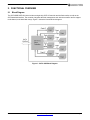
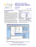
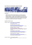
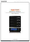
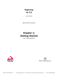
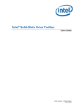
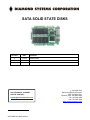
1 SATA SOLID STATE DISKS Revision Date A 11/5/10 Comment Initial Release FOR TECHNICAL SUPPORT PLEASE CONTACT: [email protected] SATA SSD User Manual Rev A Copyright 2010 Diamond Systems Corporation 1255 Terra Bella Ave. Mountain View, CA 94043 USA Tel 1-650-810-2500 Fax 1-650-810-2525 www.diamondsystems.com CONTENTS Important Safe-Handling Information .....................................................................................................................3 1. Introduction .......................................................................................................................................................4 1.1 Specifications.................................................................................................................................................5 2. Functional Overview .........................................................................................................................................6 2.1 Block Diagram ...............................................................................................................................................6 2.2 Dimensions ....................................................................................................................................................7 2.3 Connector Locations ......................................................................................................................................8 2.4 Connector Details ..........................................................................................................................................8 2.5 Cables ............................................................................................................................................................9 3. Features .............................................................................................................................................................9 3.1 ATA Mode Support ........................................................................................................................................9 3.2 Capacity Specification ...................................................................................................................................9 3.3 Read/Write Performance ...............................................................................................................................9 3.4 Software Interface....................................................................................................................................... 10 3.4.1 Command Set .................................................................................................................................... 10 3.4.2 S.M.A.R.T Technology ....................................................................................................................... 11 4. Flash Management......................................................................................................................................... 11 4.1 Error Correction / Error Detection ............................................................................................................... 11 4.2 Bad Block Management ............................................................................................................................. 11 4.3 Wear Leveling ............................................................................................................................................. 11 4.4 Power Failure Management ....................................................................................................................... 11 4.5 Quick Erase ................................................................................................................................................ 12 5. Environmental & Regulatory Specifications ............................................................................................... 12 5.1 Environmental ............................................................................................................................................. 12 5.2 Mean Time Between Failures (MTBF) ....................................................................................................... 12 5.3 Certification and Compliance ...................................................................................................................... 12 SATA SSD User Manual Rev A www.diamondsystems.com Page 2 IMPORTANT SAFE-HANDLING INFORMATION WARNING: ESD-Sensitive Electronic Equipment! Observe ESD-safe handling procedures when working with this product. Always use this product in a properly grounded work area and wear appropriate ESD-preventive clothing and/or accessories. Always store this product in ESD-protective packaging when not in use. Safe Handling Precautions The SATA SSD drives contain I/O connectors that connect to sensitive electronic components. This creates many opportunities for accidental damage during handling, installation and connection to other equipment. The list here describes common causes of failure found on boards returned to Diamond Systems for repair. This information is provided as a source of advice to help you prevent damaging your Diamond (or any vendor’s) embedded computer boards. ESD damage – This type of damage is almost impossible to detect, because there is no visual sign of failure or damage. The symptom is that the board simply stops working, because some component becomes defective. Usually the failure can be identified and the chip can be replaced. To prevent ESD damage, always follow proper ESD-prevention practices when handling computer boards. Damage during handling or storage – On some boards we have noticed physical damage from mishandling. A common observation is that a screwdriver slipped while installing the board, causing a gouge in the PCB surface and cutting signal traces or damaging components. Another common observation is damaged board corners, indicating the board was dropped. This may or may not cause damage to the circuitry, depending on what is near the corner. Most of our boards are designed with at least 25 mils clearance between the board edge and any component pad, and ground / power planes are at least 20 mils from the edge to avoid possible shorting from this type of damage. However these design rules are not sufficient to prevent damage in all situations. A third cause of failure is when a metal screwdriver tip slips, or a screw drops onto the board while it is powered on, causing a short between a power pin and a signal pin on a component. This can cause overvoltage / power supply problems described below. To avoid this type of failure, only perform assembly operations when the system is powered off. Sometimes boards are stored in racks with slots that grip the edge of the board. This is a common practice for board manufacturers. However our boards are generally very dense, and if the board has components very close to the board edge, they can be damaged or even knocked off the board when the board tilts back in the rack. Diamond recommends that all our boards be stored only in individual ESD-safe packaging. If multiple boards are stored together, they should be contained in bins with dividers between boards. Do not pile boards on top of each other or cram too many boards into a small location. This can cause damage to connector pins or fragile components. Power supply wired backwards – Our power supplies and boards are not designed to withstand a reverse power supply connection. This will destroy each IC that is connected to the power supply. In this case the board will most likely will be unrepairable and must be replaced. A chip destroyed by reverse power or by excessive power will often have a visible hole on the top or show some deformation on the top surface due to vaporization inside the package. Check twice before applying power! Bent connector pins – This type of problem is often only a cosmetic issue and is easily fixed by bending the pins back to their proper shape one at a time with needle-nose pliers. This situation can occur when pulling a ribbon cable off of a pin header. Note: If the pins are bent too severely, bending them back can cause them to weaken unacceptably or even break, and the connector must be replaced. SATA SSD User Manual Rev A www.diamondsystems.com Page 3 1. INTRODUCTION The Serial ATA Flash Drives (SAFD) is a solid-state disk (SSD) drive that contains a controller, embedded firmware, and flash media along with a male connector. Using NAND flash memory devices, the SAFD drives interface with the host allowing data to be seamlessly transferred between the host and the flash devices. The SATA SSD drive is designed with a single-chip controller, offering capacities of up to 128 gigabytes and providing full support for the SATA II high-speed interface standard. It can operate at sustained access rates of up to 100 megabytes per second, which is much faster than any other solid-state or traditional SATA drive currently available on the market. In addition to buffer management through dynamical allocation, the SSD drive adopts the specific static wearleveling scheme to allow uniform use of all storage blocks, ensuring that the lifetime of a flash media can be significantly increased and the disk performance is optimized as well. The drives provide the S.M.A.R.T. feature that follows the SATA Rev. 2.5, ATA/ATAPI-7 specifications and uses the standard SMART command B0h to read data from the drive. This feature protects the user from unscheduled downtime by monitoring and storing critical drive performance. SSD Model Description SSD-32G-XT 32GB SATA SSD flashdisk with cables SSD-64G-XT 64GB SATA SSD flashdisk with cables SATA SSD User Manual Rev A www.diamondsystems.com Page 4 1.1 Specifications Standard Serial ATA 2.5 (Gen. 2) – Serial ATA 2.5 (Gen. 2) – SATA II, 3.0Gbps – ATA-compatible command set Capacities – 32GB and 64GB Performance – Burst read/write: 300MB/sec – Sustained read: up to 160MB/sec – Sustained write: up to 135MB/sec Intelligent endurance design – Built-in hardware ECC, enabling up to 8/15 bit correction per 512 bytes – Global wear-leveling scheme together with dynamical block allocation to significantly increase the lifetime of a flash device and optimize the disk performance – Flash bad-block management – S.M.A.R.T. technology – Power Failure Management – Quick Erase NAND Flash Type: SLC Zero power data retention – No battery required for data storage Temperature ranges – Operating Temperature: -40°C to +85°C (-40°F to +185°F) – Storage: -40°C to +100°C (-40°F to +212°F) Supply voltage – +5.0V ±10% (+4.5-5.5V) Low power consumption – Active mode: 355mA (+5.0V) – Idle mode: 143mA (+5.0V) Form factor – 2.5 inch Connector – 7-pin SATA male connector – 15-pin SATA power connector RoHS compliant SATA SSD User Manual Rev A www.diamondsystems.com Page 5 2. FUNCTIONAL OVERVIEW 2.1 Block Diagram The SATA SSD SAFD 254 drive includes a single-chip SATA II Controller and the flash media, as well as the SATA standard interface. The controller integrates the flash management unit with the controller itself to support multi-channel, multi-bank flash arrays. Figure 1 shows the functional block diagram. Figure 1: SATA SSD Block Diagram SATA SSD User Manual Rev A www.diamondsystems.com Page 6 2.2 Dimensions Figure 2 shows the overall dimensions of the SATA SSD SAFD drive as listed in the table below. Dimension Millimeters (㎜) Height 5.88 ±0.10 Width 65.02 ±0.15 Length 96.35 ±0.15 Figure 2: SATA SSD Dimensions SATA SSD User Manual Rev A www.diamondsystems.com Page 7 2.3 Connector Locations The diagram in Figure 3 illustrates the position of the connectors located on the SATA SSD. Power Data Figure 3: Connector Locations 2.4 Connector Details Table 2-1 describes the SATA SSD data connector pin out and Table 2-2 the power connector pin out. Table 2-1: Data connector Name Type D1 GND D2 RxP D3 RxN D4 GND D5 TxN D6 TxP D7 GND SATA SSD User Manual Rev A Table 2-2: Power connector Description Serial Data Receiver Serial Data Transmitter www.diamondsystems.com Pin Signal/Description P1 Not used (3.3V) P2 Not used (3.3V) P3 Not used (3.3V) P4 Reserved P5 Ground P6 Ground P7 5V Pre-Charge P8 5V P9 5V P10 Ground P11 Reserved P12 Ground P13 Not used (12V Pre-Charge) P14 Not used (12V) P15 Not used (12V) Page 8 2.5 Cables Two cables are provided with every SATA SSD product as shown in the table below. Diamond P/N Description Connects to… 6981002 SATA Power cable, 3” Power 6981007 SATA Data cable, 3” Data 3. FEATURES 3.1 ATA Mode Support The SATA SSD provides ATA mode support as follows: 3.2 Up to PIO mode-4 Up to Multiword DMA mode-2 Up to UDMA mode-5 Capacity Specification Capacity specification of the SATA SSD product family is shown in Table 3-1. It lists the specific capacity, the total bytes available, and the maximum LBA. Only LBA addressing applied for these capacities. Table 3-1 Capacity Specification 3.3 Capacity Total Bytes Max LBA 32 GB 32,296,140,800 63,078,400* 64 GB 64,609,058,816 126,189,568* Read/Write Performance Performance of the SASA SSD is shown in Table 3-2. Table 3-2 Performance specification Capacity 32 GB 64 GB Sustained Read (MB/s) 159 159 Sustained Write (MB/s) 136 136 Performance SATA SSD User Manual Rev A www.diamondsystems.com Page 9 3.4 3.4.1 Software Interface Command Set Table 3-3 summarizes the ATA commands supported by the SATA SSD. Table 3-3: Command Set Command 1 2 3 4 5 6 Code FR SC SN CY DH Check-Power-Mode E5H - - - - D 8 - Execute-Drive-Diagnostic 90H - - - - D - Flush-Cache E7H - - - - D - Identify-Drive ECH - - - - D - Idle E3H - Y - - D - Idle-Immediate E1H - - - - D - Initialize-Drive-Parameters 91H - Y - - Y - C8H or C9H - Y Y Y Y Y C4H - Y Y Y Y Y Read-Sector(s) 20H or 21H - Y Y Y Y Y Read-Verify-Sector(s) 40H or 41H - Y Y Y Y Y Recalibrate 10H - - - - D - Security-Disable-Password F6H - - - - D - Security-Erase-Prepare F3H - - - - D - Security-Erase-Unit F4H - - - - D - Security-Freeze-Lock F5H - - - - D - Security-Set-Password F1H - - - - D - Security-Unlock F2H - - - - D - 7XH - - Y Y Read-DMA Read-Multiple Seek 7 LBA Set-Features EFH Y - - - D - Set-Multiple-Mode C6H - Y - - D - Sleep E6H - - - - D - SMART B0H Y Y Y Y D Standby E2H - - - - D - Standby-lmmediate E0H - - - - D - Write-DMA CAH - Y Y Y Y Y Write-Multiple C5H - Y Y Y Y Y Write-Sector(s) 30H - Y Y Y Y Y 1. FR - Features register 2. SC - Sector Count register 3. SN - Sector Number register 4. CY - Cylinder registers 5. DH - Drive/Head register 6. LBA - Logical Block Address mode supported (see command descriptions for use) 7. Y - The register contains a valid parameter for this command. 8. For the Drive/Head register: Y means both the SAFD and Head parameters are used D means only the SAFD parameter is valid and not the Head parameter SATA SSD User Manual Rev A www.diamondsystems.com Page 10 3.4.2 S.M.A.R.T Technology S.M.A.R.T. is an acronym for Self-Monitoring, Analysis and Reporting Technology, an open standard allowing disk drives to automatically monitor their own health and report potential problems. It protects the user from unscheduled downtime by monitoring and storing critical drive performance and calibration parameters. Ideally, this should allow taking proactive actions to prevent impending drive failure. The SATA SSDs use the standard SMART command B0h to read data from the drive for SMART feature as the SATA Rev.2.6 ATA/ATAPI-7 specifications. Based on the SFF-8035i Rev. 2.0 specifications, SMART defines 3 vendor-specified SMART Attribute IDs (E5h, EAh-EBh, and E8h) in the SAFD254. They represent Flash ID, maximum erase count, average erase count, good block count, free-list block count, and firmware version information. When the SMART Utility running on the host, it analyzes and reports the disk status to the host before the SAFD254 is in critical condition. 4. FLASH MANAGEMENT 4.1 Error Correction / Error Detection The SATA SSD implements a hardware ECC scheme, based on the BCH algorithm. It can detect and correct up to 8 bits or 15 bits error in 512 bytes. 4.2 Bad Block Management Although bad blocks on the flash media are already identified by the flash manufacturer, they can also be accumulated over time during operation. The controller maintains a table that lists those normal blocks with disk data, the free blocks for wear leveling, and bad blocks with errors. When a normal block is detected broken, it is replaced with a free block and listed as a bad block. When a free block is detected broken, it is then removed from the free block list and marked as a bad block. During device operation, this ensures that newly accumulated bad blocks are transparent to the host. The device will stop file write service once there are only two free blocks left such that the read function is still available for copying the files from the disk into another. 4.3 Wear Leveling The NAND flash devices are limited by a certain number of write cycles. When using a FAT-based file system, frequent FAT table updates are required. If some area on the flash wears out faster than others, it would significantly reduce the lifetime of the whole SSD, even if the erase counts of others are far from the write cycle limit. Thus, if the write cycles can be distributed evenly across the media, the lifetime of the media can be prolonged significantly. This scheme is called wear leveling. Wear-leveling scheme is achieved both via buffer management and specific static wear leveling. They both ensure that the lifetime of the flash media can be increased, and the disk access performance is optimized as well. 4.4 Power Failure Management The Low Power Detection on the controller initiates crucial data saving before the power supplied to the device is too low. This feature prevents the device from crash and ensures data integrity during an unexpected power-off. SATA SSD User Manual Rev A www.diamondsystems.com Page 11 4.5 Quick Erase Accomplished by the Secure Erase (SE) command, which added to the open ANSI standards that control disk drives, “Quick Erase” is built into the disk drive itself and thus far less susceptible to malicious software attacks than external software utilities. It is a positive easy-to-use data destroy command, amounting to electronic data shredding. Executing the command causes a drive to internally completely erase all possible user data. This command is carried out within disk drives, so no additional software is required. Once executed, neither data nor the erase counter on the device would be recoverable, which blurs the accuracy of device lifespan. The process to erase will not be stopped until finished while encountering power failure, and will be continued when power is back on. 5. ENVIRONMENTAL & REGULATORY SPECIFICATIONS 5.1 Environmental The SATA SSD environmental specifications follow the US Military Standard MIL-STD-810F, as shown in Table 5-1. Table 5-1 Environmental Specifications Environment Temperature Humidity Vibration Shock - Operating Altitude 5.2 Specification Operating: -40°C to 85°C (-40°F to 185°F) Non-operating: -40°C to 100°C (-40°F to 212°F) 5% to 95% RH (Non-condensing) Sine wave: 5~55~5Hz (X, Y, Z) Random: 10-2000Hz, 16.3G (X, Y, Z) Acceleration: 1,500G, 0.5ms Peak acceleration: 50G, 11ms 80,000 feet Mean Time Between Failures (MTBF) Mean Time Between Failures (MTBF) is predicted based on reliability data for the individual components in the SSD drive. Although many component MTBFs are given in databases, and often these values are not really accurate, the prediction result for the SATA SSD is more than 2,000,000 hours. 5.3 Certification and Compliance The SATA SSD drive complies with the following standards: CE – EN55022/55024 FCC 47CFR Part15 Class B RoHS MIL-STD-810F SATA II (SATA Rev. 2.5) Up to ATA/ATAPI-7 ( including S.M.A.R.T.) SATA SSD User Manual Rev A www.diamondsystems.com Page 12