1
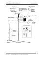
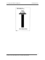
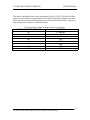
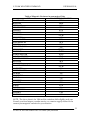
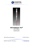
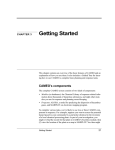
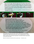
C-5 SAM
WEATHER COMMAND
User’s Manual
0302115001
Rev.00
August 14, 1992
Coastal Environmental Systems
820 First Avenue South, Seattle, WA 98134
Telephone: 206-682-6048 1-800-488-8291 Fax: 206-682-5658
www.coastalenvironmental.com
C-5 SAM WEATHER COMMAND
USER MANUAL
SOFTWARE NOTICE
ALOHA Plume Dispersion Model
ALOHA Version 5.2.1 contains a bug that will not allow interface
with automatic data downloads from weather stations (SAMs).
This bug was fixed in ALOHA Version 5.2.2 and 5.2.3.
If you have Version 5.2.1 you can get a FREE download from the
E.P.A. website –
www.epa.gov/ceppo/cameo
2
COASTAL ENVIRONMENTAL SYSTEMS (206) 682-6048
C-5 SAM WEATHER COMMAND
USER MANUAL
IMPORTANT NOTE
The nose cone of the wind monitor is removed (unscrewed) for protection
against damage during shipment. Put the nose cone back by screwing it to the
wind monitor body.
Since the nose cone has fine threads, make sure, when you put the nose cone
back onto the wind monitor body, it is not cross threaded.
3
COASTAL ENVIRONMENTAL SYSTEMS (206) 682-6048
C-5 SAM WEATHER COMMAND
USER MANUAL
4
COASTAL ENVIRONMENTAL SYSTEMS (206) 682-6048
C-5 SAM WEATHER COMMAND
USER MANUAL
1.0 Description
The C-5 SAM Weather Command is designed with the ruggedness and ease
of use that has made the Weatherpak so popular. C-5 SAM computes
running averages of vector wind speed, vector wind direction, air
temperature and stability of the wind. This data, along with the
instantaneous measurements of wind speed, direction and air temperature
(and optionally Relative Humidity), are updated on the display screen every
30 seconds.
C-5 SAM can be used as a stand alone station independent of any computer
or supporting electronics. It can be used for routine monitoring or in
conjunction with the ALOHA plume dispersion model. With or without the
dispersion model, the data will allow you to estimate downwind travel time
and distance, locate potential impact areas, and target your evacuation zone
or identify it in pre-planning practices.
List of Components
1. Display/Controller Box. The data is displayed in real time on a Liquid
Crystal Display with and LED backlight. The Display/Controller
contains the electronics for collection and display of the weather data.
It includes an AC/DC converter to allow you to power the unit from
line power. A plug on the Display/Controller allows you to input data
directly into your computer for historical record keeping, or to feed
data in real time to the ALOHA dispersion model.
2. Sensor Head. This includes the air temperature sensor, the wind
monitor with propeller and propeller nut, a sealed electronics housing,
and a data cable to go to the Display/Controller box. The electronics
in the sensor head prevent radio and electronic noise from interfering
with the data.
3. Sighting compass. This compass allows you to easily align the sensor
head N arrow to TRUE North. Failure to do this will result in incorrect
data.
4. Mounting platform (optional). There are portable tower or vehicle
mount options.
5
COASTAL ENVIRONMENTAL SYSTEMS (206) 682-6048
C-5 SAM WEATHER COMMAND
USER MANUAL
2.0 Setup
2.1 Align the sensor head toward TRUE NORTH.
Unless you live in Madison, Wisconsin or Birmingham, Alabama,
when you hold up a compass it does not point to TRUE NORTH. A
compass points to MAGNETIC NORTH and you want C-5 SAM
aligned to TRUE NORTH because that is how all maps are oriented.
The easiest way to align the sensor head with north is to use the
sighting compass provided with the C-5 SAM.
1. Determine the magnetic variation of the city where the C-5 SAM
will be used (your local airport or weather bureau can help). A list
of some major cities is provide in this manual. Once you have
determined the magnetic variation for your particular city, (say 20°
E for Seattle or 5° W for Charleston) then you must take this into
account when sighting the compass.
2. Hold the sighting compass at eye level with your arm fully
extended. Be sure the sights in front and in back of the compass
are lined up with your line of vision. Turn your body or move
your arm until you also have the compass N in line with the sights.
3. Now compensate for the magnetic variation of your city. For an
EAST variation SUBTRACT; for a WEST variation ADD the
degrees to 360° (NORTH). If you are in Seattle you must subtract
20°. (Remember that on a compass 360 and 0 are both at North).
So move your arm until you can see approximately where 340°
would be on the compass. NOW your sight is aimed at TRUE
NORTH.
4. While holding your aim at TRUE NORTH, select some nonmoving object in the distance (a tree, a pole, a crack in a building)
as your north reference. The north reference should be at least 100
feet away but, the farther away, the better.
6
COASTAL ENVIRONMENTAL SYSTEMS (206) 682-6048
C-5 SAM WEATHER COMMAND
USER MANUAL
7
COASTAL ENVIRONMENTAL SYSTEMS (206) 682-6048
C-5 SAM WEATHER COMMAND
USER MANUAL
5. Slip the sensor head on to whatever you are mounting it to,
(portable tower, vehicle mount, or a permanently mounted pole).
Use the north indicator tab (white plastic arrow head) to aim the
sensor head to your chosen north reference. After north
alignment, tighten down the locking knob on the neck of the
sensor head.
6. If you raise the sensor head now – BE SURE TO KEEP THE
ARROW HEAD ALIGNED WITH YOUR NORTH REFERENCE.
If for some reason you move the C-5 SAM during its use, you must
keep it aimed constantly North. (Remember, if you move C-5 SAM
your reference point may no longer be due north of the new
location.) If it is not possible to keep the North alignment while
moving the C-5 SAM, you must turn the C-5 SAM off and restart it
when it is in the new position and again aimed TRUE NORTH.
2.2. Connect all cables.
1. The Display/Controller box should be wall mounted or attached
firmly to a base.
2. Route the data cable from the sensor head to the
Display/Controller box. Attach the data cable to the Display/
Controller box via the 15 pin connector on side of the box.
3. Plug in the power supply then plug the power supply into a 110
outlet.
4. Plug in the cable from the sensor head.
5. A cable can be run from the Din Plug on the Display/Controller to
a Comm port of a computer. For a MacIntosh computer, a
standard Din 8 cable can be used. For a IBM P.C. type computer, a
cable can be purchased from your C-5 SAM dealer.
2.3 Turn on power.
Turn on the power switch on the front of the Display/Controller box. The power
light next to the switch comes on to indicate the C-5 SAM is on.
If you wish to connect the Display/Controller directly to your vehicle or other
power, eliminate the power supply and wire in 9 – 12 volts DC (minimum 300
milliamps) directly to the controller. On the power plug, the tip is (+) and the
ring is (-).
8
COASTAL ENVIRONMENTAL SYSTEMS (206) 682-6048
C-5 SAM WEATHER COMMAND
USER MANUAL
3.0 Operation
As soon as the C-5 SAM unit is turned on it begins sampling it’s weather sensors
at a continuous rate of once per second. The C-5 SAM processes both immediate
and average weather data. The data averages are a running five minute average,
calculated every 30 seconds. At 30 second intervals the display will be updated
to show the current weather conditions. The first display update occurs five
seconds after turning the unit on. The data light on the front panel of the
Display/Controller box will turn on briefly when the data on the display is
updated.
If the C-5 SAM unit has been out of operation for five minutes, a value of –1
(minus one) in the wind stability field indicates the average data has not been
calculated over a full five minute period. (You need a full 5 minutes to calculate
a valid number for stability).
The data on the screen appears as follows:
Wind Speed (WS)
5 minute running average (see details below) in m/s
or mph.
Wind Direction
5 minute running average of direction wind is coming
from in degrees or ordinal points (N, W, SW, etc.).
See the table that translates ordinal points to degrees.
Instantaneous
Wind Speed (IW)
Exact wind speed during last one second before
updating display. (See details below.)
Stability (STAB)
Value describing how much wind “mixing” is
occurring within the wind direction. (See details
below).
Temperature (TEMP)
5 minute running average of air temperature in °C
or °F.
9
COASTAL ENVIRONMENTAL SYSTEMS (206) 682-6048
C-5 SAM WEATHER COMMAND
USER MANUAL
Relative Humidity (RH)
5 minute running average in percentage.
Identification (ID)
Your C-5 SAM unit identification assigned at the
factory.
STABILITY
Stability of the wind is the biggest determinant of how far plume will travel
downwind. Stability is measured by electronically checking where the vane is
located every second. Since the vane in normal wind is always moving—the
stability will never be zero (unless you held the vane in place perfectly for 5
minutes).
Stability is the standard deviation of the wind direction and can range from 0 to
about 120. As was discussed you will never see zero nor will you ever see 120,
however, a wind with a stability above 25 is a fairly unstable wind. This is good
if you have a spill because it means the plume will disperse more rapidly (it will
however be broader). Bad news is a stability of 10 or less. This means the air is
not mixing much and the plume will travel much further.
For more precise downwind distances it is necessary to use a plume dispersion
model which considers the exact chemical type, all the weather conditions, how
much was spilled, etc.
5 MINUTE RUNNING AVERAGE
A 5 minute running average of the wind will always be lower than what you
think the wind speed will be. This is because the wind usually comes in gusts
and eddies, creating high speeds interspersed with low speed areas. It is not
uncommon for people to guess the wind speed at about twice as high as the 5
minute average.
INSTANTANEOUS WIND SPEED
This is the exact speed of the wind in the one second before the
Display/Controller updates the display. IT IS NOT A GUST SPEED, unless the
gust is occurring at the exact second the reading is taken. It is possible to have an
instantaneous speed of 0 to 1 in an 8 MPH average wind—it just happened to
occur during that one second.
10
COASTAL ENVIRONMENTAL SYSTEMS (206) 682-6048
C-5 SAM WEATHER COMMAND
USER MANUAL
The above calculations have been determined by the US EPA, NOAA and other
agencies to be the best representation of the meteorological conditions that will
most accurately reflect traveling distances and locations of hazardous vapors etc.
and still present the data in a timely manner.
Chart showing Ordinal compass points and degrees.
ORDINAL COMPASS POINT
DEGREES
N
0° OR 360°
NE
45°
E
90°
SE
135°
S
180°
SW
225°
W
270°
NW
315°
11
COASTAL ENVIRONMENTAL SYSTEMS (206) 682-6048
C-5 SAM WEATHER COMMAND
USER MANUAL
Table of Magnetic Variances in some major Cities
CITY
MAGNETIC VARIATION
BALTIMORE
10°W
BOSTON
16°W
CHICAGO
1°W
CHARLESTON
15°W
DALLAS
6.5°E
DENVER
11.5°
DETROIT
5.5°W
HOUSTON
6°E
KANSAS CITY
5°W
LOS ANGELES
14°E
MIAMI
3°W
NEW ORLEANS
3°E
NEW YORK
12.5°W
PHOENIX
12.5°E
PORTLAND, OR
19.5°E
SALT LAKE CITY
15°E
SAN FRANCISCO
16°E
SEATTLE
20°E
ST. LOUIS
2°E
WASHINGTON D.C.
9.5°W
ANTWERP
2°E
COPENHAGEN
0°
GENOA
1°E
HAMBURG
1°E
LISBON
7°E
LONDON
5°E
MADRID
5°E
PARIS
3.5°E
ROME
0°
STOCKHOLM
2°W
VIENNA
1°W
ZURICH
1°E
NOTE: The above chart is for 1986 and the variation shifts slightly each year.
Consult your local airport, weather service, or a marine supply dealer for the
current year magnetic variation for your location.
12
COASTAL ENVIRONMENTAL SYSTEMS (206) 682-6048