1
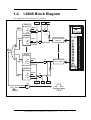
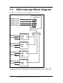
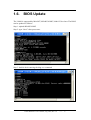
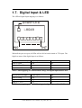
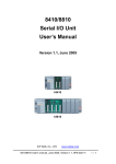
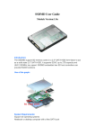
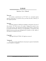
I-8048
Hardware User’s Manual
Warranty
All products manufactured by ICP DAS are warranted against
defective materials for a period of one year from the date of delivery to
the original purchaser.
Warning
ICP DAS assumes no liability for damages consequent to the use of
this product. ICP DAS reserves the right to change this manual at any
time without notice. The information furnished by ICP DAS is believed to
be accurate and reliable. However, no responsibility is assumed by ICP
DAS for its use, nor for any infringements of patents or other rights of
third parties resulting from its use.
Copyright
Copyright 2004 by ICP DAS. All rights are reserved.
Trademark
The names used for identification only maybe registered trademarks
of their respective companies.
I-8048 Hardware User’s Manual, Aug. 2004, Rev. 1.0
------
1
1.
General Introduction
The I-8048 module is an 8-channel digital input module designed for interrupt
applications. The key features of the I-8048 are as follows:
1. Input Signal:
isolated or non-isolated TTL, jumper
selectable
2. Logic high level
Isolated:
4 ~ 30V
(recommended: limit impedance when using 12~24V input)
Non-isolated TTL:
2 ~5V
3. Logic low level
4.
5.
6.
7.
Isolated:
0 ~ 1V
Non-isolated TTL:
0 ~0.8V
Isolated voltage:
2000V
Built-in isolated power supply:
5V, 200mA max.
Rising/Falling edge interrupt programmable
Must be installed in slot0, slot1, slot2, or slot3.
I-8048 Hardware User’s Manual, Aug. 2004, Rev. 1.0
------
2
1.1. Pin Assignment for the I-8048
The pin assignment for the I-8048 is as follows:
Pin 1:
Pin 2:
Pins 3 ~ 18:
Pins 19 and 20:
TTL GND, ground for non-isolated input signals
N/A
8-channel digital input
isolated power supply, 5V, 200mA max.
I-8048 Hardware User’s Manual, Aug. 2004, Rev. 1.0
------
3
1.2.
I-8048 Block Diagram
The signal flow block diagram is as follows:
Clr0
Falling
D-flipflop
Qf0
Qr0
D
Clk
Clr
Gi
High
AND
NOT
Rising
D-flipflop
D
Clk
Clr
Ef0
Er0
Isolated/TTL
In0, JP1
High
AND
OR
Rising
D-flipflop
Qr7
D
Clk
Clr
High
Isolated/TTL
In7, JP8
AND
Falling
D-flipflop
Qf7
D
Clk
Clr
NOT
High
AND
Clr7
Ef7
Er7
AND
ClrGi
Int e rrupt
CPU
I-8048 Hardware User’s Manual, Aug. 2004, Rev. 1.0
------
4
1.3.
8000 Interrupt Block Diagram
The 8000 series interrupt system block diagram is as follows:
80186
Slot0's Int
Slot1's Int
Slot2's Int
Slot3's Int
Slot4's int
IntClr4
INT0
INT1
INT2
INT3
NMI
D-filpflop
Clk
Q
Clr
Slot5's int D-filpflop
Q
Clk
IintClr5
Clr
Slot6's int
IntClr6
D-filpflop
Clk Q
Clr
Slot7's int
IntClr7
D-filpflop
Q
Clk
Clr
It is difficult for the interrupt mechanism of the I-8048 and the CPU’s NMI to work
together properly, so the I-8048 must be installed in slot0, slot1, slot2, or slot3 only.
I-8048 Hardware User’s Manual, Aug. 2004, Rev. 1.0
------
5
1.4. I-8048 I/O Control Register
The I/O control registers are as follows:
Offset
Read (BASE+Offset) Address
Write (BASE+Offset) Address
0
Clear interrupt input 0, Clr0
N/A
1
Clear interrupt input 1, Clr1
N/A
2
Clear interrupt input 2, Clr2
N/A
3
Clear interrupt input 3, Clr3
N/A
4
Clear interrupt input 4, Clr4
N/A
5
Clear interrupt input 5, Clr5
N/A
6
Clear interrupt input 6, Clr6
N/A
7
Clear interrupt input 7, Clr7
N/A
8
Read Rising Enable Register
Set Rising Enable Register
Er7/Er6/Er5/Er4/Er3/Er2/Er1/Er0
D7=Er7, D0=Er0
Er7/Er6/Er5/Er4/Er3/Er2/Er1/Er0
D7=Er7, D0=Er0
9
Read Falling Enable Register
Ef7/Ef6/Ef5/Ef4/Ef3/Ef2/Ef1/Ef0
D7=Ef7, D0=Ef0
Set Falling Enable Register
Ef7/Ef6/Ef5/Ef4/Ef3/Ef2/Ef1/Ef0
D7=Ef7, D0=Ef0
0x0A
Read Global Interrupt Status, Gi
D0=Gi
Force Interrupt to LOW state about
0.1uS, ClrGi
0x0B
Read Rising Interrupt Status
N/A
Qr7/Qr6/Qr5/Qr4/Qr3/Qr2/Qr1/Qr0
0x0C
Read Falling Interrupt Status
N/A
Qf7/Qf6/Qf5/Qf4/Qf3/Qf2/Qf1/Qf0
0x0D
Read Digital Input
Di7/Di6/Di5/Di4/Di3/Di2/Di1/Di0
N/A
The BASE address for the 8000 series is as follows:
Slot0
BASE=0x80
Slot1
BASE=0xA0
Slot2
BASE=0xC0
Slot3
BASE=0xE0
Slot4
BASE=0x140
Slot5
BASE=0x160
Slot6
BASE=0x180
Slot7
BASE=0x1a0
I-8048 Hardware User’s Manual, Aug. 2004, Rev. 1.0
------
6
1.5.
Isolated or TTL Input
The input signal can be either isolated or TTL input as follows:
V cc
V in +
In 0
V in -
JP1
JP1 ~ JP8 in the DOWN position will select the
isolated input 1 ~ 8
The TTL input block diagram is as follows:
V in V in +
V cc
In 0
JP1
JP1 ~ JP8 in the UP position will select the TTL
input 1 ~ 8
JP1 Select Input 0
JP2 Select Input 1
J
JP3 Select Input 2
JP4 Select Input 3
JP5 Select Input 4
JP6 Select Input 5
JP7 Select Input 6
JP8 Select Input 7
Isolated input (default)
I-8048 Hardware User’s Manual, Aug. 2004, Rev. 1.0
TTL input
------
7
1.6.
BIOS Update
The I-8048 is supported by MiniOS7, 8K040330.IMG, 2004/03/30 or later. The BIOS
can be updated as follows:
Step 1: upload 8K040330.IMG
Step 2: type “bios1” then press enter.
Step 3: double check entering the diag.exe command
I-8048 Hardware User’s Manual, Aug. 2004, Rev. 1.0
------
8
1.7. Digital Input & LED
The LED to Digital Input mapping is as follows:
power LED
i -8048
IN0
IN7
When all the pins are open, all LEDs will be ON for both isolated or TTL input. The
high/low status of the digital input is as follows:
JPn selected isolated input
Digital Input
LED
Input is OPEN
High
OFF
Input is 3.5 ~ 30V
Low
ON
Input is 0 ~ 1V
High
OFF
NOTE: when applying an isolated HIGH voltage, the digital input will be LOW.
JPn selected TTL input
Digital Input
LED
Input is OPEN
High
OFF
Input is 2 ~ 5V
High
OFF
Input is 0 ~ 0.8V
Low
ON
NOTE: when applying a TTL HIGH voltage, the digital input will be HIGH
I-8048 Hardware User’s Manual, Aug. 2004, Rev. 1.0
------
9
Referring to Section. 1.4, the address of digital input is BASE+0x0D, so the DIAG
command can be used to determine the I-8048 and INP commands to read the digital
input as follows:
In this example, there is one I-8048 module installed in the first slot, slot0, the address
of the digital input=0x80+0x0d=0x8D. The first reading of this digital input is 0x29
and the second reading is 0xD7. The following example shows two I-8048 modules
installed in the first and second slots.
I-8048 Hardware User’s Manual, Aug. 2004, Rev. 1.0
------
10
1.8. Enable Rising/Falling Interrupt
The digital input signals determined in Section 1.7 can be programmed to interrupt the
CPU when their states are changed. The possible types are as follows:
Digital Input
Interrupt CPU
Rising Edge Interrupt
Digital Input
Interrupt CPU
Falling Edge Interrupt
Digital Input
Interrupt CPU
Both Edge Interrupt
NOTE: when referring to Section 1.7, applying isolated HIGH voltage and TTL
HIGH voltage, the digital input will be different. That is to say, their rising edge
and falling edge are also different. The user should be certain of whether the
interrupt is rising or falling edge before starting to code the ISR program.
I-8048 Hardware User’s Manual, Aug. 2004, Rev. 1.0
------
11
Referring to Section 1.4, writing to BASE+8 can enable a rising edge interrupt and
writing to BASE+9 will enable a falling edge interrupt. Writing to both BASE+8 and
BASE+9 can enable a rising and falling edge interrupt. Some code examples are as
follows:
Write to
BASE+8
Write to
BASE+9
0
0
Disable all interrupts
1
0
Enable rising edge interrupt of channel_0
0
1
Enable falling edge interrupt of channel_0
1
1
Enable rising and falling edge interrupt of channel_0
2
0
Enable rising edge interrupt of channel_1
0
2
Enable falling edge interrupt of channel_1
2
2
Enable rising and falling edge interrupt of channel_1
4
4
Enable rising and falling edge interrupt of channel_2
8
8
Enable rising and falling edge interrupt of channel_3
0x10
0x10
Enable rising and falling edge interrupt of channel_4
0x20
0x20
Enable rising and falling edge interrupt of channel_5
0x40
0x40
Enable rising and falling edge interrupt of channel_6
0x80
0x80
Enable rising and falling edge interrupt of channel_7
0x0F
0xF0
Enable rising edge interrupt of channel_1 to 3, and
falling edge interrupt of channel_ 4 to 7
0xF0
0x0F
Enable rising edge interrupt of channel_4 to 7, and
falling edge of channel_ 0 to 3
0xFF
0
Enable rising edge interrupt of channel_1 to 7
0
0xFF
Enable falling edge interrupt of channel_1 to 7
0xFF
0xFF
Enable rising and falling edge interrupt of channel_1 to 7
Operation
I-8048 Hardware User’s Manual, Aug. 2004, Rev. 1.0
------
12
1.9. ISR for Slot0 ~ 3
Referring to Section 1.3, the interrupt systems of the 8000 series can be divided into
two groups, group1 and group2. Group1 is from slot0 to slot3, and these interrupts are
connected to the CPU’s int0 to 3, respectively. Group2 is from slot4 to slot7, and these
interrupts are connected to the NMI of the CPU. The I-8048 can only be installed in
slot0 ~ slot3.
Demo programs 1 to 6 below are designed for Group1. Refer to these demo programs
for additional coding information. The sample libraries are as follows:
z isr1.c in demo1, 3, and 4 is designed for slot0 only.
z isr2.c in demo2 is designed for slot1 only
z isr3.c in demo5 is designed for slot0 and slot1.
z
isr4.c in demo6 is designed for slot0, 1, 2, and 3.
New 8000L.lib
I-8048 Hardware User’s Manual, Aug. 2004, Rev. 1.0
------
13
1.10. Clear Interrupt
Referring to Section 1.2, the interrupt signal will be latched until a clear interrupt
signal is active. Refer to Section 1.4 for the addresses of clear interrupt signals.
The global interrupt, Gi, is shared by all eight signals. If any single interrupt does not
clear to LOW, then all interrupts will be blocked and the CPU will not be able to
receive any further interrupts. That is to say, the programmer should ensure that the
code clears the interrupt and make sure that the global interrupt, Gi, is LOW in
normal conditions. The global interrupt, Gi, can be read back from BASE+0x0A.
Writing to BASE+0x0D will force the Gi to LOW for about 0.1uS. The Gi will return
to its previous state after writing. This mechanism will ensure that the I-8048 works
properly in a shared interrupt system. The only way to clear the Gi is to clear all the
Qfn and Qrn values listed in Section 1.2. Reading from BASE+n will clear both Qfn
and Qrn values. Refer to Demo1 ~ Demo6 for more coding examples.
Notes:
1. If any Qfn or Qrn value is HIGH, the Gi will be HIGH to block all further
interrupts
2. All Qrn values can be read from BASE+0x0B
3. All Qfn values can be read from BASE+0x0C
4. The Gi can be read from BASE+0x0D
5. Reading from BASE+n will clear both Qrn and Qfn values to LOW
6. Writing to BASE+0x0D will force the Gi to LOW for about 0.1uS
I-8048 Hardware User’s Manual, Aug. 2004, Rev. 1.0
------
14
1.11.
Isolation Voltage Test
ICP DAS has a strict and detailed endurance test for withstanding a voltage of 2000V
for 5min, which was used with the I-8048. As shown in the figure below, two cables
are connected to the isolation and non-isolation input terminals of the Voltage
Endurance Tester (I-7122) and the connected with the I-8048. Two types of test
modes can be set on the I-7122. The first is a Breakdown test and the second is an Arc
test.
Once the cables are connected, the test can be started. The voltage endurance test is
performed for five minutes and, once the success of the test has been determined, the
test is repeated for verification. This test proves that the I-8048 has very high voltage
endurance performance.
Return probe
High Voltage probe
Figure: Block Diagram
I-8048 Hardware User’s Manual, Aug. 2004, Rev. 1.0
------
15
1.12.
ESD Test
Walking across an insulated floor surface can cause a person to become
electrostatically charged, and, over a period of time, it is possible for the human body
to be charged to a capacity of several kilovolts. The TRANSIENT-2000 Tester can
simulate the transients of human body electrostatic discharge (ESD), and was used to
simulate ESD in order to test the I-8048.
First, the ESD test file (ESDTest.exe) was downloaded to an I-8411 module and
executed. The EUT (Equipment Under Test) is the I-8048. If static electricity causes a
shock to the I-8048 module, the test program will display an error message on the PC
monitor.
There are two types of ESD test. The first is to test the connection shock at 4KV ten
times, and the second is to test the air shock at 8KV ten times. Both tests were
performed on the same terminal. There are 20 metal points on the module that can be
touched and each one was tested in turn. In all cases the testing program returned
negative results showing that there were no adverse effects to either the I-8411
Embedded Controller or the I-8048 module, so the I-8048 ESD test proved to be very
successful.
“Shock”
Running status
I-8048 Hardware User’s Manual, Aug. 2004, Rev. 1.0
------
16
2.
Demo Programs
1. demo1
• The I-8048 is installed in the first slot, slot0
• Only channel_0 is enabled
• Enter 0, 1, 2 or 3 to select the active rising/falling edge
2. demo2
• The I-8048 is installed in the second slot, slot1
• Only channel_0 is enabled
• Enter 0, 1, 2 or 3 to select the active rising/falling edge
3. demo3
• The I-8048 is installed in the first slot, slot0
• Channel_0 and channel_1 are enabled
• Enter 0, 1, 2 or 3 to select the active rising/falling edge
4. demo4
• The I-8048 is installed in the first slot, slot0
• All channels and both rising/falling edge are enabled
5. demo5
• One I-8048 is installed in the first slot, slot0
• Another I-8048 is installed in the second slot, slot1
• All channels and both rising/falling edge are enabled
6. demo6
•
•
Four I-8048 modules are installed in slot0, 1, 2, and 3
All channels and both rising/falling edge are enabled
I-8048 Hardware User’s Manual, Aug. 2004, Rev. 1.0
------
17
2.1.
z
z
z
z
z
z
z
z
z
Library Files
8048\readme.txt
8048\lib\8000_2L.lib
8048\lib\8000.H
8048\lib\8K040330.IMG
8048\EsdTest\*.*
8048\Demo1\*.*
…………….
…………….
8048\Demo6\*.*
Æ read this file first
Æ 8000 series library file, large model
Æ 8000_2L.lib declaration file
Æ MiniOS7 image dated 2004/03/30
Æ ESD testing program
Æ demo1
Æ demo6
The following files can be found in the demo directory:
z readme.txt
Æ read this file first
z demon.exe
Æ execution file that can be download to the 8000 series module,
n=1/2/3/4/5/6
z main.c
Æ main program
z ISR1.c
Æ designed for slot0 and slot1
z ISR2.c
Æ designed for slot0, slot1, slot2, slot3
The user can modify ISR1.c, ISR2.c to fit any special requirements.
I-8048 Hardware User’s Manual, Aug. 2004, Rev. 1.0
------
18
2.2.
Step 1:
Step 2:
Step 3:
Step 4:
Step 5:
Demo1
set JP1 to be either isolated or TTL input
install the I-8048 to the first slot, slot0
apply the input signal to In0+, In0- for isolated input or
In0+, TTL GND for non-isolated input
download demo1.exe to the I-8048
for rising edge testing, press 1
for falling edge testing, press 2
for rising and falling edge testing, press 3
The following diagram shows that no I-8048 was detected in slot0:
The following diagram shows the rising edge test: (press 1)
I-8048 Hardware User’s Manual, Aug. 2004, Rev. 1.0
------
19
The following diagram shows the falling edge test: (press 2)
The following diagram shows the test for both rising/falling edges: (press 3)
I-8048 Hardware User’s Manual, Aug. 2004, Rev. 1.0
------
20
2.3. Demo2
Step 1:
Step 2:
Step 3:
Step 4:
Step 5:
set JP1 to be either isolated or TTL input
install the I-8048 to the second slot, slot1
apply the input signal to In0+, In0- for isolated input or
In0+, TTL GND for non-isolated input
download demo2.exe to the I-8048
for rising edge testing, press 1
for falling edge testing, press 2
for rising and falling edge testing, press 3
The testing diagram is similar to Section 2.2
I-8048 Hardware User’s Manual, Aug. 2004, Rev. 1.0
------
21
2.4. Demo3
Step 1:
Step 2:
Step 3:
Step 4:
Step 5:
Step 6:
set JP1 and JP2 to be either isolated or TTL input
install the I-8048 to the second slot, slot1
apply the input signal to In0+, In0-, In1+, In1- for isolated input or
In0+, In1+, TTL GND for non-isolated input
download demo3.exe to the I-8048
channel0 setting
for rising edge testing, press 1
for falling edge testing, press 2
for rising and falling edge testing, press 3
channel1 setting
for rising edge testing, press 1
for falling edge testing, press 2
for rising and falling edge testing, press 3
Note: the settings for channel0 and channel1 can be different.
The testing results diagram is similar to Section 2.2.
I-8048 Hardware User’s Manual, Aug. 2004, Rev. 1.0
------
22
2.5. Demo4
Step 1:
Step 2:
Step 3:
Step 4:
set JP1 ~ JP8 to be either isolated or TTL input
install the I-8048 to the second slot, slot1
apply input signals to In?+, In?- for isolated input or
In?+, TTL GND for non-isolated input
download demo4.exe to the I-8048
Note: the demo will enable both rising/falling edges of all channels.
The testing results diagram is similar to Section 2.2
2.6. Demo5
This demo is similar to demo4.c except that there are two I-8048 modules installed in
slot0 and slot1, respectively.
2.7. Demo6
This demo is similar to demo4.c except that there are four I-8048 modules installed in
slot0, slot1, slot3, and slot4, respectively.
I-8048 Hardware User’s Manual, Aug. 2004, Rev. 1.0
------
23