1
WizPLC User’s Guide
Version 2.0
Warranty/Trademarks
This document is for information only and is subject to change without
prior notice. It does not represent a commitment on the part of PC Soft
International Ltd. No part of this document may be reproduced or
transmitted in any form or by any means, electronic or mechanical,
including photocopying or recording, for any purpose, without written
permission from PC Soft International Ltd.
If you find any problems in the documentation, please report them in
writing. PC Soft does not warrant that this documentation is error-free.
© Copyright 1997, 1998, 1999 by PC Soft International Ltd.
WizPLC is a trademark of PC Soft International Ltd. Windows 95,
Windows NT are registered trademarks of Microsoft Corporation.
All other products and brand names are trademarks of their respective
companies.
WIZF\WIZPLCUGE\2.0\0599
ii WizPLC User’s Guide
Table of Contents
Chapter 1 Using this Guide.................................................................1-1
About This Guide ......................................................................................................... 1-2
What You Should Know .............................................................................................. 1-4
Typographical Conventions ....................................................................................... 1-4
How to Use This Guide ............................................................................................... 1-5
Registering Your Product ........................................................................................... 1-5
Receiving Technical Support ..................................................................................... 1-5
Chapter 2 Introducing WizPLC ...........................................................2-1
What is WizPLC? ......................................................................................................... 2-2
WizPLC Features ......................................................................................................... 2-3
WizPLC Combines Wizcon Power with SoftLogic Technology ................................. 2-3
Tight Integration with Wizcon..................................................................................... 2-3
High Speed at Low Cost ............................................................................................ 2-3
High Data Integrity ..................................................................................................... 2-3
Short Development Time ........................................................................................... 2-4
Low Plant Downtime .................................................................................................. 2-4
Standard Wizcon I/O Drivers ..................................................................................... 2-4
IEC 61131-3 Compliant ............................................................................................. 2-4
Reusable Code .......................................................................................................... 2-5
Easy to Learn, Implement and Maintain .................................................................... 2-5
Standard Library ........................................................................................................ 2-5
Project Documentation .............................................................................................. 2-5
Monitoring & Debugging ............................................................................................ 2-6
Simulation .................................................................................................................. 2-6
Breakpoints ................................................................................................................ 2-7
Flow Control............................................................................................................... 2-7
Sampling Trace.......................................................................................................... 2-7
Table of Contents iii
WizPLC Terms & Concepts......................................................................................... 2-8
Components of a Program ........................................................................................ 2-8
Program Organization Units (POUs) ......................................................................... 2-8
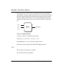
Program ..................................................................................................................... 2-9
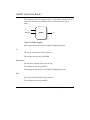
Functions ................................................................................................................. 2-11
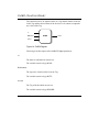
Function Block ......................................................................................................... 2-15
Instances of Function Blocks ................................................................................... 2-15
Tags ......................................................................................................................... 2-18
Resources................................................................................................................ 2-18
Libraries ................................................................................................................... 2-19
Cycles ...................................................................................................................... 2-19
Sleep / Interface Wizcon.......................................................................................... 2-19
Structure .................................................................................................................. 2-20
Languages .................................................................................................................. 2-23
Instruction List (IL) ................................................................................................... 2-23
Structured Text (ST) ................................................................................................ 2-24
Sequential Function Chart (SFC)............................................................................. 2-24
Function Block Diagram (FBD) ................................................................................ 2-26
Chapter 3 Installing WizPLC ...............................................................3-1
System Requirements ................................................................................................. 3-2
WizPLC and the Windows NT Registry ..................................................................... 3-3
WizPLC System Files ................................................................................................ 3-4
Changing the Default Directory.................................................................................. 3-4
Communication Drivers ............................................................................................. 3-5
Once Installation is Complete .................................................................................... 3-5
Starting WizPLC ........................................................................................................... 3-6
WizPLC and Wizcon Integration ................................................................................ 3-6
Activating WizPLC Directly from Wizcon ................................................................... 3-6
Configuring WizPLC .................................................................................................... 3-7
Cycles ........................................................................................................................ 3-8
Hard Real Time............................................................................................................. 3-9
iv WizPLC User’s Guide
Chapter 4 WizPLC Editors & Languages ...........................................4-1
The Declaration Editor ................................................................................................ 4-2
Input Variables ........................................................................................................... 4-3
Output Variables ........................................................................................................ 4-3
Input/Output Variables ............................................................................................... 4-4
Auto Declare .............................................................................................................. 4-4
Global Variables........................................................................................................... 4-6
Editing Global Variables............................................................................................. 4-6
Local Variables .......................................................................................................... 4-7
Constants................................................................................................................... 4-7
Keywords ................................................................................................................... 4-8
Variable Declaration................................................................................................... 4-8
AT Declaration ........................................................................................................... 4-9
The Shortcut Expansion Feature ............................................................................... 4-9
Line Numbers in the Declaration Editor ................................................................... 4-11
Adding Variables to the Declaration Table............................................................... 4-12
Declaration Editor in Online Mode ........................................................................... 4-12
Syntax Coloring........................................................................................................ 4-16
Comment ................................................................................................................. 4-17
The Text Editors......................................................................................................... 4-18
The Text Editors in Online Mode ............................................................................. 4-20
Breakpoint Positions ................................................................................................ 4-21
How to Set a Breakpoint .......................................................................................... 4-22
Deleting Breakpoints................................................................................................ 4-22
What Happens at a Breakpoint?.............................................................................. 4-23
Line Numbers of the Text Editor .............................................................................. 4-23
The Instruction List Editor ........................................................................................ 4-24
Flow Control............................................................................................................. 4-24
The Editor for Structured Text ................................................................................. 4-25
The Graphic Editors .................................................................................................. 4-26
Label ........................................................................................................................ 4-26
Comments in Networks ........................................................................................... 4-26
Insert Ø Network (after) or Insert Ø Network (before) ............................................ 4-27
The Network Editors in Online Mode ....................................................................... 4-27
The Function Block Diagram Editor ......................................................................... 4-28
Cursor Positions in the FBD .................................................................................... 4-29
How to Set the Cursor.............................................................................................. 4-30
Insert Ø New Declaration ........................................................................................ 4-31
Insert Ø Jump.......................................................................................................... 4-31
Table of Contents v
Insert Ø RETURN.................................................................................................... 4-32
Insert Ø Operator .................................................................................................... 4-32
Insert Ø Function or Insert Ø Function Block.......................................................... 4-33
Insert Ø Input........................................................................................................... 4-34
Insert Ø Output........................................................................................................ 4-34
Extras Ø Negate...................................................................................................... 4-35
Extras Ø Set/Reset.................................................................................................. 4-35
Extras Ø Zoom ........................................................................................................ 4-36
Cut, Copy, Insert and Delete in FBD........................................................................ 4-36
The Function Block Diagram in Online Mode .......................................................... 4-37
The Ladder Diagram Editor ..................................................................................... 4-38
Cursor Positions in the LD Editor............................................................................. 4-39
Insert Ø Contact ...................................................................................................... 4-40
Insert Ø Parallel Contact ......................................................................................... 4-41
Insert Ø Function Block ........................................................................................... 4-41
Insert Ø Coil............................................................................................................. 4-42
POUs with EN Inputs ............................................................................................... 4-42
Insert Ø Operator with EN ....................................................................................... 4-43
Insert Ø Function Block with EN.............................................................................. 4-43
Insert Ø Function with EN........................................................................................ 4-43
Insert Ø Insert to POU............................................................................................. 4-44
Insert Ø Jump.......................................................................................................... 4-44
Insert Ø RETURN.................................................................................................... 4-45
Extras Ø Insert after ................................................................................................ 4-45
Extras Ø Insert under .............................................................................................. 4-45
Extras Ø Insert above.............................................................................................. 4-45
Extras Ø Negate...................................................................................................... 4-46
Extras Ø Set/Reset.................................................................................................. 4-46
The Ladder Diagram in Online Mode....................................................................... 4-47
The Structured Flow Chart....................................................................................... 4-47
Select Blocks in the SFC ......................................................................................... 4-48
Insert Ø Step Transition (before)............................................................................. 4-48
Insert Ø Step Transition (after)................................................................................ 4-49
Insert Ø Alternative branch (right) ........................................................................... 4-49
Insert Ø Alternative branch (left) ............................................................................. 4-49
Insert Ø Parallel branch (right) ................................................................................ 4-49
Insert Ø Parallel branch (left) .................................................................................. 4-50
Insert Ø Jump.......................................................................................................... 4-50
Insert Ø Transition Jump ......................................................................................... 4-50
Insert Ø Add input action......................................................................................... 4-50
Insert Ø Add output action....................................................................................... 4-50
vi WizPLC User’s Guide
Extras Ø Insert parallel branch (right) ..................................................................... 4-51
Extras Ø Insert after ................................................................................................ 4-51
Extras Ø Zoom action/Transition............................................................................. 4-51
Extras Ø Delete Action/Transition ........................................................................... 4-51
Extras Ø Step attributes .......................................................................................... 4-52
SFC Flags ................................................................................................................ 4-53
Extras Ø Time limit overview................................................................................... 4-55
Extras Ø SFC overview ........................................................................................... 4-56
Extras Ø Options ..................................................................................................... 4-57
Extras Ø Associate action ....................................................................................... 4-57
Extras Ø USE IEC steps ......................................................................................... 4-58
Project Ø Add action ............................................................................................... 4-58
SFC in Online mode ................................................................................................ 4-59
Chapter 5 WizPLC & Wizcon...............................................................5-1
General.......................................................................................................................... 5-2
WizPLC Combines Wizcon Power with SoftLogic Technology ................................. 5-2
Versatility ................................................................................................................... 5-5
Reusability ................................................................................................................. 5-6
Integration with Wizcon .............................................................................................. 5-7
Standard Wizcon I/O Drivers and RS-232 Connectivity ............................................ 5-8
WizPLC Tags and the WizPLC VPI (Vpiwnwzp) ........................................................ 5-9
Tags ........................................................................................................................... 5-9
WizPLC VPI ............................................................................................................. 5-12
Chapter 6 Resources...........................................................................6-1
Overview ....................................................................................................................... 6-2
Global Variables........................................................................................................... 6-3
Editing Global Variables............................................................................................. 6-3
Multiple Variable Lists................................................................................................ 6-3
Access Variables ....................................................................................................... 6-4
Global Variables......................................................................................................... 6-5
Variable Configuration ............................................................................................... 6-6
Docufile ...................................................................................................................... 6-8
WizPLC Configuration............................................................................................... 6-11
Table of Contents vii
Task Configuration .................................................................................................... 6-13
Which Task is Handled? .......................................................................................... 6-14
Working in Task Configuration ................................................................................ 6-14
Sampling Trace .......................................................................................................... 6-18
Selecting Variables to be Displayed ........................................................................ 6-21
Displaying Trace Sampling ...................................................................................... 6-22
Watch and Receipt Manager..................................................................................... 6-26
Watch and Receipt Manager in Offline Mode .......................................................... 6-27
Watch and Receipt Manager in Online Mode .......................................................... 6-28
Forcing Values ......................................................................................................... 6-30
Chapter 7 Debugging ..........................................................................7-1
General.......................................................................................................................... 7-2
Simulation .................................................................................................................. 7-2
Sampling Trace.......................................................................................................... 7-2
Breakpoints ................................................................................................................ 7-2
Single Steps............................................................................................................... 7-5
Single Cycle ............................................................................................................... 7-5
Online Operations........................................................................................................ 7-6
Monitoring .................................................................................................................. 7-6
Flow Control............................................................................................................... 7-6
The Watch and Receipt Window ................................................................................ 7-7
Watch Window in Offline Mode ................................................................................. 7-7
Help Manager ............................................................................................................ 7-8
Watch Window in Online Mode ................................................................................. 7-8
Watch Lists ................................................................................................................ 7-9
Forcing Values ........................................................................................................... 7-9
Watch and Receipt Options ....................................................................................... 7-9
Sampling Trace .......................................................................................................... 7-11
What is Sampling Trace? ........................................................................................ 7-11
Starting the Sampling Trace .................................................................................... 7-12
Inserting Trace Variables......................................................................................... 7-13
Selecting Displayed Variables ................................................................................. 7-14
Stopping the Trace .................................................................................................. 7-15
Sampling Trace Options .......................................................................................... 7-16
viii WizPLC User’s Guide
Chapter 8 Menus & Options................................................................8-1
The WizPLC Main Window .......................................................................................... 8-2
Menu Bar ................................................................................................................... 8-3
Toolbar....................................................................................................................... 8-3
Object Organizer........................................................................................................ 8-4
Divider........................................................................................................................ 8-5
Workspace ................................................................................................................. 8-6
Message Window ...................................................................................................... 8-6
Status Bar .................................................................................................................. 8-6
Context Menu............................................................................................................. 8-7
Options ......................................................................................................................... 8-8
Project Ø Options ...................................................................................................... 8-8
Load & Save .............................................................................................................. 8-9
User Information ...................................................................................................... 8-11
Editor........................................................................................................................ 8-12
Autodeclaration ........................................................................................................ 8-13
Autoformat ............................................................................................................... 8-13
Declarations as tables ............................................................................................. 8-13
Tab-Width ................................................................................................................ 8-13
Font.......................................................................................................................... 8-14
Marks ....................................................................................................................... 8-14
Bitvalues .................................................................................................................. 8-15
Desktop.................................................................................................................... 8-15
Colors....................................................................................................................... 8-16
Directories................................................................................................................ 8-17
Build ......................................................................................................................... 8-18
Passwords ............................................................................................................... 8-19
Managing Projects..................................................................................................... 8-21
File Ø New............................................................................................................... 8-21
File Ø Open ............................................................................................................. 8-21
File Ø Close............................................................................................................. 8-22
File Ø Save.............................................................................................................. 8-22
File Ø Save as ......................................................................................................... 8-22
File Ø Print............................................................................................................... 8-24
File Ø Documentation Setup ................................................................................... 8-25
File Ø Exit ................................................................................................................ 8-27
Project Ø Check ...................................................................................................... 8-27
Project Ø Compile ................................................................................................... 8-28
Project Ø Rebuild all................................................................................................ 8-28
Table of Contents ix
Project Ø Documentation ........................................................................................ 8-29
Project Ø Export ...................................................................................................... 8-32
Project Ø Import ...................................................................................................... 8-32
Project Ø Compare.................................................................................................. 8-33
Project Ø Copy ........................................................................................................ 8-33
Project Ø Project Info .............................................................................................. 8-34
Project Ø Global Search.......................................................................................... 8-36
Project Ø Global Replace........................................................................................ 8-36
Project Ø Trace Changes........................................................................................ 8-36
User Groups ............................................................................................................ 8-37
Project Ø Passwords for User Groups .................................................................... 8-38
Objects: Insertion, Deletion, and So On .................................................................. 8-39
Object ...................................................................................................................... 8-39
Folders ..................................................................................................................... 8-39
New Folder............................................................................................................... 8-41
Expand Node and Collapse Node............................................................................ 8-41
Project Ø Delete Object........................................................................................... 8-41
Project Ø Add Object............................................................................................... 8-42
Project Ø Rename Object ....................................................................................... 8-43
Project Ø Convert object ......................................................................................... 8-43
Project Ø Copy object.............................................................................................. 8-44
Project Ø Open object ............................................................................................. 8-44
Project Ø Object Security ........................................................................................ 8-45
Project Ø View Instance .......................................................................................... 8-47
Project Ø Show Call Tree........................................................................................ 8-47
Project Ø Show Cross Reference ........................................................................... 8-48
Project Ø Show unused Variables........................................................................... 8-49
Extras Previous Version .......................................................................................... 8-49
General Editing Functions ........................................................................................ 8-50
Edit Ø Undo ............................................................................................................. 8-50
Edit Ø Redo ............................................................................................................. 8-50
Edit Ø Cut ................................................................................................................ 8-51
Edit Ø Copy ............................................................................................................. 8-52
Edit Ø Insert............................................................................................................. 8-52
Edit Ø Delete ........................................................................................................... 8-53
Edit Ø Find............................................................................................................... 8-54
Edit Ø Find Next ...................................................................................................... 8-55
Edit Ø Replace ........................................................................................................ 8-55
Edit Ø Help Manager ............................................................................................... 8-56
x WizPLC User’s Guide
Edit Ø Next Error ..................................................................................................... 8-57
Edit Ø Previous Error............................................................................................... 8-58
General Online Functions ......................................................................................... 8-59
Online Ø Login......................................................................................................... 8-59
Online Ø Logout ...................................................................................................... 8-60
Online Ø Run........................................................................................................... 8-60
Online Ø Stop .......................................................................................................... 8-60
Online Ø Reset ........................................................................................................ 8-60
Online Ø Toggle Breakpoint .................................................................................... 8-61
Online Ø Breakpoint Dialog..................................................................................... 8-62
Online Ø Step over .................................................................................................. 8-63
Online Ø Step In ...................................................................................................... 8-63
Online Ø Single Cycle ............................................................................................. 8-64
Online Ø Write Values or Force Values .................................................................. 8-64
Online Ø Release Force .......................................................................................... 8-65
Online Ø Show Callstack......................................................................................... 8-65
Online Ø Display Flow Control ................................................................................ 8-66
Online Ø Simulation................................................................................................. 8-66
Online Ø Communication Parameters .................................................................... 8-67
Window Arranging ..................................................................................................... 8-68
Window Ø Tile vertical............................................................................................. 8-68
Window Ø Tile horizontal ........................................................................................ 8-68
Window Ø Cascade................................................................................................. 8-68
Window Ø Arrange Symbols ................................................................................... 8-68
Window Ø Close all ................................................................................................. 8-69
Window Ø Messages .............................................................................................. 8-69
Help to the Rescue .................................................................................................... 8-70
Help Ø Contents ...................................................................................................... 8-70
Help Main Window................................................................................................... 8-71
Context Sensitive Help............................................................................................. 8-73
Chapter 9 Libraries ..............................................................................9-1
Creating Libraries ........................................................................................................ 9-2
Adding Additional Elements to an Existing Library .................................................... 9-5
Creating External Libraries......................................................................................... 9-7
Creating a WizPLC Library ........................................................................................ 9-7
Creating a DLL........................................................................................................... 9-8
Table of Contents xi
Example of a WizPLUser.dll ...................................................................................... 9-9
Updating External Libraries...................................................................................... 9-13
Debugging External Libraries................................................................................... 9-16
Setting Up WizPLC Runtime to Run in Debug Mode............................................... 9-16
Setting up Microsoft Developer Studio..................................................................... 9-16
Running User DLL in Debug Mode.......................................................................... 9-17
Chapter 10 Runtime...........................................................................10-1
Running a Project ...................................................................................................... 10-2
The Runtime Window .............................................................................................. 10-3
Configuring Runtime ................................................................................................ 10-6
Creating a Bootable Project...................................................................................... 10-9
Chapter 11 A Sample Project............................................................11-1
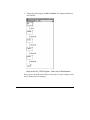
Program Structure ..................................................................................................... 11-2
Writing a Program...................................................................................................... 11-3
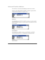
Creating POUs......................................................................................................... 11-3
PLC_PRG - First Level of Development ................................................................ 11-12
Building a Diagram in SFC...................................................................................... 11-13
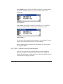
Inserting Steps ....................................................................................................... 11-13
Actions and Transition Conditions ......................................................................... 11-15
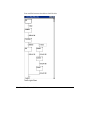
PLC_PRG - Second Level of Development........................................................... 11-16
The Result ............................................................................................................. 11-20
Testing a Program ................................................................................................... 11-21
Traffic Light Simulation .......................................................................................... 11-21
Integrating with Wizcon .......................................................................................... 11-22
Appendix A Using the Keyboard....................................................... A-1
Use of Keyboard ..........................................................................................................A-2
Key Combinations .......................................................................................................A-3
xii WizPLC User’s Guide
Appendix B Data Types...................................................................... B-1
Standard Data Types ...................................................................................................B-2
Data Types.................................................................................................................B-2
BOOL .........................................................................................................................B-2
Integer Data Types ....................................................................................................B-2
REAL / LREAL ...........................................................................................................B-3
STRING .....................................................................................................................B-4
Time Data Types .......................................................................................................B-4
Defined Data Types .....................................................................................................B-5
ARRAY.......................................................................................................................B-5
Pointer........................................................................................................................ B-6
Enumeration ..............................................................................................................B-7
Structures ..................................................................................................................B-8
References ..............................................................................................................B-10
Appendix C IEC Operators................................................................. C-1
Arithmetic Operators...................................................................................................C-2
ADD ...........................................................................................................................C-2
MUL ...........................................................................................................................C-3
SUB............................................................................................................................C-4
DIV .............................................................................................................................C-4
MOD...........................................................................................................................C-5
INDEXOF ...................................................................................................................C-6
SIZEOF ......................................................................................................................C-6
Bitstring Operators......................................................................................................C-7
AND ...........................................................................................................................C-7
OR..............................................................................................................................C-8
XOR ...........................................................................................................................C-8
NOT ...........................................................................................................................C-9
Bit-Shift Operators.....................................................................................................C-10
SHL ..........................................................................................................................C-10
SHR .........................................................................................................................C-10
ROL..........................................................................................................................C-11
ROR .........................................................................................................................C-12
Table of Contents xiii
Selection Operators...................................................................................................C-13
SEL ..........................................................................................................................C-13
MAX .........................................................................................................................C-14
MIN ..........................................................................................................................C-15
LIMIT........................................................................................................................C-15
MUX .........................................................................................................................C-16
Comparison Operators..............................................................................................C-17
GT ............................................................................................................................C-17
LT.............................................................................................................................C-18
LE.............................................................................................................................C-18
GE............................................................................................................................C-19
EQ............................................................................................................................C-20
NE ............................................................................................................................C-21
Address Operators ....................................................................................................C-22
ADR .........................................................................................................................C-22
Content Operator .......................................................................................................C-23
Calling Operator.........................................................................................................C-24
CAL ..........................................................................................................................C-24
Appendix D Standard Library Elements ........................................... D-1
Type Conversion Functions .......................................................................................D-2
BOOL_TO Conversions.............................................................................................D-2
TO_BOOL Conversions.............................................................................................D-3
Conversion between Integral Number Types ............................................................D-4
REAL_TO-/ LREAL_TO Conversions........................................................................D-4
TIME_TO/TIME_OF_DAY Conversions ....................................................................D-5
DATE_TO/DT_TO Conversions ................................................................................D-6
STRING_TO Conversions .........................................................................................D-6
TRUNC ......................................................................................................................D-7
Numeric Functions ......................................................................................................D-8
ABS............................................................................................................................D-8
SQRT .........................................................................................................................D-8
LN ..............................................................................................................................D-8
LOG ...........................................................................................................................D-8
EXP............................................................................................................................D-8
SIN .............................................................................................................................D-8
COS ...........................................................................................................................D-8
xiv WizPLC User’s Guide
TAN............................................................................................................................D-8
ASIN...........................................................................................................................D-9
ACOS.........................................................................................................................D-9
ATAN .........................................................................................................................D-9
EXPT .........................................................................................................................D-9
String Functions ........................................................................................................D-10
LEN ..........................................................................................................................D-10
LEFT ........................................................................................................................D-10
RIGHT......................................................................................................................D-11
MID ..........................................................................................................................D-12
CONCAT..................................................................................................................D-12
INSERT....................................................................................................................D-13
DELETE ...................................................................................................................D-14
REPLACE ................................................................................................................D-14
FIND.........................................................................................................................D-15
Bi-stable Function Blocks.........................................................................................D-16
SR ............................................................................................................................D-16
RS ............................................................................................................................D-16
SEMA.......................................................................................................................D-17
Trigger ........................................................................................................................D-18
R_TRIG....................................................................................................................D-18
F_TRIG ....................................................................................................................D-19
Counter .......................................................................................................................D-21
CTU .........................................................................................................................D-21
CTD .........................................................................................................................D-21
CTUD .......................................................................................................................D-22
Timer ...........................................................................................................................D-23
TP ............................................................................................................................D-23
TON .........................................................................................................................D-24
TOF..........................................................................................................................D-25
Appendix E Operands in WizPLC...................................................... E-1
Operands ......................................................................................................................E-2
Constants .....................................................................................................................E-2
BOOL Constants........................................................................................................E-2
TIME Constants .........................................................................................................E-2
Table of Contents xv
DATE Constants ........................................................................................................E-3
TIME_OF_DAY Constants.........................................................................................E-4
DATE_AND_TIME Constants....................................................................................E-4
Number Constants.....................................................................................................E-4
REAL/LREAL Constants............................................................................................E-5
STRING Constants ....................................................................................................E-6
Variables .......................................................................................................................E-7
System Flags .............................................................................................................E-7
Accessing Variables for Arrays, Structures and POUs..............................................E-7
Addresses.....................................................................................................................E-8
Address......................................................................................................................E-8
Memory Location .......................................................................................................E-9
Functions....................................................................................................................E-10
Appendix F Build Error ...................................................................... F-1
Appendix G WizPLC Library Elements .............................................G-1
Controller Tag-1 (Function Block) ............................................................................ G-3
PID Controller Tag Parameters ................................................................................ G-5
Controller Tag-2 (Function Block) ............................................................................ G-8
Block File Access (Function Block)........................................................................ G-13
ComToString (Function Block) ............................................................................... G-19
Start ........................................................................................................................ G-19
ComName............................................................................................................... G-19
DataLen .................................................................................................................. G-20
The length of transmission...................................................................................... G-20
StringToCom (Function Block) ............................................................................... G-23
Start ........................................................................................................................ G-23
ComName............................................................................................................... G-23
StringData ............................................................................................................... G-24
GetTimeMsec (Function Block) ............................................................................... G-27
GetTime (Function Block) ........................................................................................ G-28
GetDateFull (Function Block) .................................................................................. G-29
xvi WizPLC User’s Guide
GetDate (Function Block)......................................................................................... G-31
ScaleBlock (Function Block) ................................................................................... G-32
MiMav8 (Function Block) ......................................................................................... G-35
MedSel (Function Block).......................................................................................... G-41
GetBit (Function Block)............................................................................................ G-43
PutBit (Function Block)............................................................................................ G-44
IntToChar (Function Block) ..................................................................................... G-46
IntToString (Function Block) ................................................................................... G-47
RealToWord (Function Block) ................................................................................. G-48
StringToReal (Function Block) ................................................................................ G-49
StringToWord (Function Block) .............................................................................. G-50
StatusBlock (Function Block).................................................................................. G-51
TPO (Function Block) ............................................................................................... G-54
PlaySound (Function Block).................................................................................... G-57
Index ......................................................................................................I-1
Table of Contents xvii
xviii WizPLC User’s Guide
Chapter 1
Using this Guide
About this chapter:
This chapter describes how to use this guide, as follows:
About this Guide, the following page, describes the chapters in this
user’s guide.
What You Should Know , page 1-5, describes things you should know
before you start to use WizPLC.
Typographical Conventions , page 1-5, describes the typographical
conventions used in this guide.
How to Use this Guide , page 1-6, suggests an approach to this book for
both first time and experienced users of WizPLC.
Registering Your Product, page 1-6, describes how to register your
product and how to receive technical support.
Using this Guide 1-1
About This Guide
The guide consists of the following chapters and appendices:
Chapter 1, Using This Guide, covers basic information about the user’s
guide.
Chapter 2, Introducing WizPLC , introduces WizPLC and the concepts
and terms you will use while working with WizPLC. This chapter also
describes the various languages that can be used with WizPLC.
Chapter 3, Installing WizPLC, describes the necessary steps for getting
ready to use WizPLC, including minimum hardware requirements, and
how to install and configure the software.
Chapter 4, WizPLC Editors & Languages, describes the WizPLC
editors for the various languages that can be used. The most commonly
used functions and options are also explained.
Chapter 5, WizPLC & Wizcon , explains the interconnection and
relationship between WIZCON and WizPLC and outlines the advantages
of a combined system.
Chapter 6, Resources, describes the resources in the Object Organizer
used to configure and organize your project and to trace variable values.
Chapter 7, Debugging, describes the debugging facilities of WizPLC
and how to use them.
Chapter 8, Menus & Options , details each WizPLC menu and describes
all the operational options they offer.
Chapter 9, Libraries, describes how to create internal libraries with one
of the WizPLC languages, and how to create and debug external
libraries.
1-2 WizPLC User’s Guide
Chapter 10, Runtime, describes how to run a program.
Chapter 11, A Sample Project, describes the basic flow of operations
for working with WizPLC. A running example is included to illustrate
each step of the various processes involved.
Appendix A, Using the Keyboard, describes how to use using keyboard
commands to run WizPLC.
Appendix B, Data Types, details WizPLC data types.
Appendix C, IEC Operators, describes the IEC operators that can be
used with WizPLC.
Appendix D, Standard Library Elements, details the contents of the
WizPLC standard library.
Appendix E, Operands in WizPLC, describes the operands in WizPLC.
Appendix F, Build Error, lists the various error messages that may be
encountered while working with WizPLC and suggests corrective
actions to be taken.
Appendix G, WizPLC Library Elements, details the contents of the
WizPLC library elements.
Using this Guide 1-3
What You Should Know
Before you start using WizPLC and working through the User’s Guide,
you should be familiar with the Windows NT operating system. You
should also know:
■
How to operate an IBM PC or compatible
■
The basics of PLC programming
■
The basics of Wizcon
Typographical Conventions
This guide uses the following typographical conventions:
Ø
This symbol indicates a menu or menu path, including the item within
the menu that you need to select in order to perform the task.
Example: Menu Ø Operator
Examples are displayed in Arial font.
1-4 WizPLC User’s Guide
How to Use This Guide
If you are using WizPLC for the first time, you can proceed in one of the
following ways:
■
Read this guide from cover to cover, exactly as it is presented.
■
First read Chapters 1 through 6. These chapters provide you with
basic information on WizPLC’s installation procedure and
guidelines for designing a project. Then read the additional chapters,
depending on the tasks that you want to perform.
■
If you are an experienced user, read Chapter 2 to learn about
WizPLC’s features and then use the Table of Contents and the Index
to find the particular information you need.
Registering Your Product
You are important to us, and it’s important for us to know our
customers. Registering your WizPLC product enables us to provide you
with better service and important notifications about your product.
Please take the time to complete the Licensing Agreement included with
your product, and return it to your local distributor.
Receiving Technical Support
You can receive technical support from your local distributor by phone
or through the Bulletin Board System (BBS). To receive prompt support,
make sure that you complete the WizPLC Registration Form and send it
to your local distributor.
Using this Guide 1-5
1-6 WizPLC User’s Guide
Chapter 2
Introducing WizPLC
About this chapter:
This chapter describes WizPLC’s features, explains commonly used
terms, and gives a short overview of the various programming languages
that can be used, as follows:
What is WizPLC?, the following page, describes WizPLC.
WizPLC Features, page 2-3, describes the WizPLC main features.
WizPLC Terms & Concepts , page 2-8, describes the most commonly
used terms and concepts related to WizPLC.
Languages, page 2-23, describes the textual and graphical languages
supported by WizPLC.
Introducing WizPLC 2-1
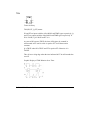
What is WizPLC?
WizPLC is a "SoftPLC." WizPLC enables you to write control logic
programs with the powerful language constructs of the IEC 61131-3
standard. The IEC 61131-3 is an international standard for programming
languages of PLC’s. WizPLC offers the entire range of languages
described in this standard.
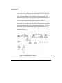
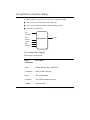
WizPLC consists of two parts: a programming system (WizPLC
Development) and a runtime system (WizPLC Runtime), which are both
described in this user’s guide.
WizPLC is a complete development system for your Windows NT
station which allows you to significantly reduce application
development time.
WizPLC Development:
■
Is a programming tool.
■
Is a monitoring & debugging tool.
■
Is an integrated tool within the Wizcon SCADA system.
■
Enables project management.
WizPLC Runtime:
■
Is a SoftPLC which runs compiled code on a Windows NT realtime
processor.
■
Communicates with I/Os.
■
Exchanges data with Wizcon.
■
Exchanges data with WizPLC Development.
All process and data can be monitored and controlled by the Wizcon
SCADA system. All tags defined in Wizcon are automatically accessible
within the associated WizPLC project; you don’t have to write your tags
twice.
2-2 WizPLC User’s Guide
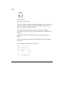
WizPLC Features
This section describes WizPLC main features.
WizPLC Combines Wizcon Power with SoftLogic Technology
WizPLC is PC-based logic control software especially created to be
integrated with Wizcon, PC Soft’s most advanced SCADA system.
Based on the fieldbus technology, WizPLC eliminates the need for
complex wiring between field devices and proprietary PLCs, enabling
you to develop both PLC programs and SCADA applications in one PC
environment. By offering integrated control development, execution and
operator interface in one package, WizPLC cuts application
development time and maintenance costs, increases performance, and
provides high data integrity, regardless of the hardware used.
Tight Integration with Wizcon
WizPLC is tightly integrated with Wizcon, creating one working
environment and minimizing the learning process. Also, WizPLC takes
full advantage of Wizcon’s features and capabilities, including advanced
networking features, online configuration and high performance.
High Speed at Low Cost
WizPLC logic runs as an extremely fast 32-bit native application under
Windows NT, in either the same PC that runs Wizcon or in a separate
PC, providing the speed and capacity of a large PLC at a fraction of the
cost.
High Data Integrity
Since WizPLC communicates directly with the I/O devices, it can read
changes faster without losing any data. This ensures high data integrity
throughout the process.
Introducing WizPLC 2-3
Short Development Time
WizPLC makes building your application faster, easier and more costeffective than ever before by combining the design and implementation
of the application’s control, logic and user interface into a single process
that can be performed by one developer. WizPLC supplies all the tools
required to build a sophisticated SCADA system from scratch, while
combining topdown and bottomup approaches. Also, since tags can be
shared, they are defined only once and then used at any time during
logic design or modification.
Low Plant Downtime
WizPLC allows online changes of the logic without stopping the
execution of the control logic programs, saving the high costs of plant
downtime.
Standard Wizcon I/O Drivers
WizPLC uses available Wizcon 32-bit DLL-based I/O drivers, including
fast fieldbus drivers such as Profibus DP, DeviceNet, Lonwork, CAN
and Interbus-S.
IEC 61131-3 Compliant
WizPLC fully supports all the IEC 61131-3 languages, including the
textual languages such as Structured Text (ST) and Instruction List (IL),
as well as graphical languages, including Function Block Diagram
(FBD), Sequential Function Chart (SFC), and Ladder Diagram (LD).
The IEC 61131-3 international standard defines:
■
Data declaration and addressing.
■
PLC programming structuring.
■
Syntax and semantics of five programming languages.
2-4 WizPLC User’s Guide
Reusable Code
Because WizPLC applications are based on IEC 61131-3 standards,
application code can be reused for the development of applications for
different fieldbus drivers.
Easy to Learn, Implement and Maintain
In addition to full compliance with IEC 61131-3, and complete
integration with Wizcon, WizPLC includes a number of tools and
utilities that make it easy to learn, implement and maintain. These
include tracing and monitoring utilities, simulation modes, debugging
tools, and utilities for creating cross-references and call trees.
Standard Library
WizPLC supports all IEC 61131-3 standard functions and is equipped
with a Standard Library which includes:
■
Functions
■
Function blocks
■
Edge detection
■
Counters
■
Timers
Project Documentation
The entire project can be documented or exported into a text file at any
time.
Introducing WizPLC 2-5
Monitoring & Debugging
The debugging functions of WizPLC help you locate logical bugs in
your program.
WizPLC allows you to set breakpoints in case of programming errors.
When execution has stopped, you can examine all program data at this
point. The single step function allows you to check the logical
correctness of your program, step by step.
As an additional debugging tool, WizPLC allows the forcing of program
variables and inputs/outputs on certain values. Flow control enables you
to check which program lines are performed, and shows you the value of
each variable used in these lines as the code is performed.
In Online mode, the visible variable declarations are followed by the
monitoring of their current values in the controller.
Simulation
In Simulation mode, the user program runs without reading inputs or
writing outputs. All online functions can be used in this mode, allowing
you to test the logical correctness of your program without any
hardware.
When all errors are removed, you can switch to simulation mode, log
into the simulated controller and load your project into the controller.
WizPLC is then in online mode.
While performing simulations, you can manipulate your tags within
Wizcon or force the variables in WizPLC. For simulation mode, no
connection to the physical I/Os is needed. You can view the current
values of your project data in the declaration parts of each POU, as well
as in the global variable list. You can also write and force values in a
separate watch window, and you can configure the data sets that you
wish to examine.
2-6 WizPLC User’s Guide
Breakpoints
WizPLC allows you to set breakpoints. The execution of a program halts
when a breakpoint is reached. At this point, you can view all current
program data, including variable values.
Breakpoints can be set in all WizPLC editors. In the textual editors,
breakpoints are set on line numbers. In FBD and LD, breakpoints are set
on network numbers, and in SFC, breakpoints are set on steps.
A wide variety of additional tools, such as Single Step and Single cycle,
enable you to control and monitor the progress of your programs (to
check the logical correctness) .
Flow Control
The snapshot enables you to display the values of variables during a
cycle by defining a snap shot area and making a snap shot. Then any
variable in a line in the snap shot area is monitored with the current
value at the execution of the line without halting the execution.
Sampling Trace
Sampling Trace allows you to trace the progress of program values,
depending on the so-called trigger event. This is the falling or rising
edge of a previously defined Boolean variable (trigger variable).
WizPLC enables you to trace up to 500 values of up to 20 variables.
Sampling Trace allows you to trace the values of variables and to
display the values as a curve.
After writing and testing your program, you can switch from simulation
mode to online mode. In online mode, the physical inputs are read and
the physical outputs are written.
Introducing WizPLC 2-7
WizPLC Terms & Concepts
The following sections explain the most commonly used terms and
concepts related to WizPLC.
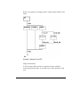
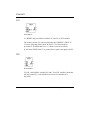
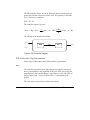
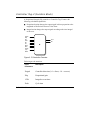
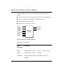
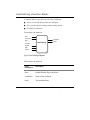
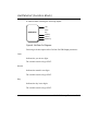
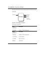
Components of a Program
Project
A project contains all the objects of a controller program and is saved in
a special project file (with the extension .pro). Each project is saved in
one *.pro file. Projects are composed of the following elements:
■
Tasks
■
POUs
■
Structures
■
Global variable list and Wizcon tags
■
Libraries
■
Watch variables
Each project starts with the Program Organization Unit named
PLC_PRG (refer to the next section).
Program Organization Units (POUs)
Functions, function blocks, and programs are considered POUs. Each
POU consists of a declaration part and a body. The body is programmed
in one of the following IEC 61131-3 programming languages:
■
Structured Text (ST)
■
Instruction List (IL)
■
Function Block Diagram (FBD)
2-8 WizPLC User’s Guide
■
Ladder Diagram (LD)
■
Sequential Function Chart (SFC)
WizPLC supports all IEC 61131-3 Standard POUs. Also, a special POU
called PLC_PRG, which is automatically included in every program,
serves as an entry point to the WizPLC program. This POU is the POU
to be executed at the beginning of each WizPLC cycle.
Note that while POUs can call other POUs, recursions are not allowed.
Program
A Program is a POU which returns one or more values when executed.
Instances of a program are not allowed. All values of a program are kept
from one execution of the program to the next.
An example of a simple program is shown below:
Example of a Program
Introducing WizPLC 2-9
Programs can be invoked within programs and function blocks. An
invocation of a program within a function is not allowed.
If a POU calls a program and changes the values of the program, these
changes will remain unaltered until the next invocation, even if the
program is called from a different POU.
On the other hand, a POU that calls a function block can only change the
values of a certain instance of a function block (local or global).
The following are some examples of invocations of the program
described above:
In IL:
CAL
PRGexample
In ST:
PRGexample;
In FBD:
The POU PLC_PRG is a special program. It is the first POU created in a
new project. During each WizPLC cycle, this POU is called exactly
once. Never delete or rename this POU, if you don’t use tasks.
If ’Project’ ’Add Object’ is executed for the first time after a new
project was created, the default setting in the POU dialog is a POU
called PLC_PRG. You should not change this default setting.
If tasks were defined, the project may not contain a PLC_PRG, since the
sequence of execution depends on the task assignment. PLC_PRG is
always the main program in a single-task program.
2-10 WizPLC User’s Guide
Functions
A function is a POU which may accept several parameters as inputs and
return one and only one parameter as an output. By default, a function
result (output) is Boolean.
Each function must be declared as a certain type. The name of the
function is always followed by a colon and the type (for example,
FUNCTION Fct: INT).
➤
To change the type of function result:
■
If the Declarations as Tables option is active:
1. Click on the Info tab. The current setting is displayed.
2. Type the desired type over the current type definition. For
example, BOOL for boolean, INT for integer.
■
If the Declarations as Tables option is not active:
Type the desired type over the current type definition. For example,
BOOL for boolean, INT for integer in the following format:
FUNCTION functionname:Type Where functionname is the name of the
function and Type is the type of result.
A value must also be assigned to the function. The name of the function
is used as an output variable. The value of the function must be of the
declared type. This type may be any type, including arrays or structures.
Introducing WizPLC 2-11
The following figure illustrates a function named FBD_Example in
FBD. It receives three Boolean inputs and returns one Boolean output.
Example of a Function
In ST, the invocation of a function can be used as an operand in an
expression.
Functions do not contain internal state information; different invocations
of a function with the same arguments (input parameters) always return
the same value (output).
2-12 WizPLC User’s Guide
Below are a number of examples of function invocations:
In IL:
LD
7
FBD_Example
2,4
ST
Result
In ST:
Result:= FBD_Example(7, 2, 4);
In FBD, the function can be called as shown below:
In SFC, a function can only be invoked within a step or transition.
Function codes can be written in any language except SFC. The example
program for testing the CheckBounds function accesses areas outside the
limits of a defined array.
The CheckBounds function ensures that the TRUE value is assigned to
position A[7] instead of A[10].
Introducing WizPLC 2-13
This allows to correct accesses outside the array boundaries.
Test program of the CheckBounds function
Attention: If you defined a function called CheckBounds in your
project, you can use it to automatically check for exceeding range limits
in your project. The name of the function is reserved and should not be
changed. The following figure shows an example, how to implement this
function:
Example for implementing the CheckBounds function
2-14 WizPLC User’s Guide
Function Block
A function block is a POU that returns one or more values when
executed.
Instances of Function Blocks
Multiple named instances (copies) of a function block can be created.
Each instance has an associated identifier (the name of the instance) and
a data structure containing its outputs, inputs and internal variables.
Like variables, instances are defined in the local variable list, by
declaring an identifier with the name of a function block as Type.
Below is an example of the declaration of an instance of the function
block IL_EXAMPLE; named MyInstance:
MyInstance:IL_EXAMPLE
All values of a function block are kept from one execution of the
function block to the next. Therefore, invocations of the same function
block with the same arguments (input variables) will not always return
the same output values.
Introducing WizPLC 2-15
The figure below shows a function block named IL_EXAMPLE
programmed in IL with one input variable and two output variables.
Example of a Function Block
Function blocks are invoked by using the name of the instance to be
retrieved.
The variables of a function block can be addressed by typing the name
of the instance followed by a point and the name of the variable.
2-16 WizPLC User’s Guide
The following examples illustrate invocations of the function block,
IL_EXAMPLE, described on the previous page:
In IL:
Example - Invocation of a Function Block in IL
Below is the same function block call in ST:
Example - Invocation of a Function Block in ST
Introducing WizPLC 2-17
Below is the same function block call in FBD:
Example - Invocation of a Function Block in FBD
In SFC, function blocks can only be invoked within steps or transitions.
Tags
Tags are data defined in Wizcon and implicitly declared in WizPLC. In
online mode, WizPLC and Wizcon continually exchange tag values.
All tag types may be inserted in WizPLC. Dummy, compound and PLC
tags, as well as Remote Wizcon tags can be inserted into your WizPLC
program. However, the type of tags used must conform to the syntax
used within the POU.
Resources
Resources are used to configure and arrange your project and to trace
the values of variables, as follows:
■
Global variables which can be used throughout the project.
■
Control configuration to configure your hardware.
■
Task configuration to control your program by means of tasks.
2-18 WizPLC User’s Guide
■
Trace recording for graphical recording of variable values.
■
Watch and Receipt manager for viewing and setting variable values.
See also, Chapter 6, Resources.
Libraries
You can link a number of libraries to your project. POUs of a linked
library can be used just like POUs defined within the project. The
standard.lib library (included in WizPLC) contains all IEC standard
functions and function blocks. The pcs.lib library contains many useful
library function blocks, such as control elements, communication blocks,
file handling and so on.
Cycles
WizPLC Runtime works in cycles. Each cycle consists of the following
steps:
■
Read All Inputs
■
Execute Logic
■
Write All Outputs
■
Sleep / Interface Wizcon
Sleep / Interface Wizcon
The first three steps listed above are basic and common to most PLCs.
The last step is critical for integration with Wizcon.
Each cycle can be configured to run for a predefined number of
milliseconds and is accurate due to the realtime priority used under
Windows NT.
Introducing WizPLC 2-19
Full determinism is achieved with our hard realtime version. For more
details, refer to Chapter 10, Runtime.
The time set as the cycle time depends on your hardware and the number
of consecutive programs running under Windows NT. The actual time
the cycle runs is deducted from the set time and yields the time left for
other applications (besides WizPLC Runtime) to run on your system.
Tset -
Telpased
=
Tsleep
Structure
A structure is a data element containing a number of elements. The
components of a structure can be of any type, including structures.
Structure declarations must have the following syntax:
TYPE <Struct_Name>
STRUCT
<Variable Declaration 1>
.
.
<Variable Declaration n>
END_STRUCT
END_TYPE
2-20 WizPLC User’s Guide
➤
To insert a new structure:
1. Change the Object Class from POU to Structure (see example
below). A list of existing structures is displayed.
Changing the Object Class
2. Select Project and then Add Object.
3. The New data type window is displayed.
New Structure Window
4. Enter a name for the new structure and click OK.
Introducing WizPLC 2-21
Below is an example of a structure definition:
Example - Structure Definition Task
A task controls the execution of a number of programs or function block
instances.
According to the IEC 61131-3 there are cyclic tasks, event triggered
tasks and time triggered tasks. When using tasks, there is no need to use
a PLC_PRG. For more details, see Chapter 8, WizPLC Menus &
Options.
2-22 WizPLC User’s Guide
Languages
WizPLC allows you to work in any of the following languages:
Textual languages:
■
Instruction List (IL)
■
Structured Text (ST)
Graphical languages:
■
Sequential Function Chart (SFC)
■
Function Block Diagram (FBD)
■
Ladder Diagram (LD)
Instruction List (IL)
An Instruction List (IL) consists of a series of instructions. Each
instruction starts in a new line and contains an operator and one or more
operands, separated by commas.
An instruction can be prefaced by a label, which is composed of the
label name and a colon.
A comment must be the last element in a line. Empty lines can be
inserted between instructions.
Example:
LD 17
ST lint
(* Comment *)
GE 5
Introducing WizPLC 2-23
JMPC
next
LD idword
EQ istruct.sdword
STN
test
next:
Structured Text (ST)
The Structured Text consists of a series of statements. These can be
executed conditionally ("IF..THEN..ELSE") or repeatedly
("WHILE..DO").
Example:
IF value < 8 THEN
WHILE value < 7 DO
value := value + 1;
END_WHILE;
END_IF;
Sequential Function Chart (SFC)
The Sequential Function Chart is a graphical language, which enables
the programmer to describe the chronological succession of different
actions within a project. Resembling flow charts, the flow of SFC
programs are easy to monitor and especially suited for batch control.
2-24 WizPLC User’s Guide
Below is an example of a diagram in SFC, edited with the WizPLC SFC
editor:
Example - Network in an SFC
Steps and Actions
A POU written in SFC consists of a sequence of steps, which are
connected by directed links. A so-called action can be attached to each
step.
Introducing WizPLC 2-25
Transition
Transitions are placed between steps. A condition is attached to a
transition. Conditions consist either of a Boolean variable, an address or
an expression with a Boolean result. A Boolean constant (TRUE,
FALSE) may also be used.
Active Step
A step is called active while its action is being executed.
When a SFC-POU is executed, the first action executed is the action
attached to the initial step (double bordered).
Each step has a flag which stores the state of the step. This flag is TRUE
when the step is active; otherwise it is FALSE. The identifier for the flag
is the step name. It is implicitly declared within the SFC POU, thus you
may not declare any variable with a name of an existing step.
After the execution of a step, the next transition is executed. If the result
is TRUE, the next step is performed in the next processor cycle.
Function Block Diagram (FBD)
The Function Block Diagram is a graphical programming language.
FBDs consist of a sequence of networks, each containing a structure that
represents a logical or arithmetic expression, the invocation of a function
block, a jump or a return statement. FBDs can handle long chains of
logic, are easy to understand and especially suited for analog
calculations.
2-26 WizPLC User’s Guide
The following is an example of a typical network in FBD, as it appears
in WizPLC:
Example - Network in an FBD
Introducing WizPLC 2-27
2-28 WizPLC User’s Guide
Chapter 3
Installing WizPLC
About this chapter:
This chapter describes WizPLC’s system requirements and explains how
to install and configure your system, as follows:
System Requirements, the following page, describes WizPLC system
requirements.
Starting WizPLC, page 3-6, describes how to start WizPLC in different
environments.
Configuring WizPLC, page 3-8, describes how to configure WizPLC to
work with your specific hardware.
Hard Real Time, page 3-10, describes how to set up WizPLC to work
with Hard Real Time.
Installing WizPLC 3-1
System Requirements
Before you install WizPLC on your system, verify that you have the
following:
Hardware: 586, 120 MHz IBM PC or higher (or compatible)
Memory: 64 MB minimum + additional memory according to the size of
your Wizcon application
Hard Disk: 120 MB minimum free
Display: VGA, SVGA or any graphic adapter that supports the operating
system desktop
Mouse: Any PC compatible mouse
Communication: Communication interface card, as required by your
I/O-based system
Operating System: Microsoft Windows NT
Network: If networking is required, it must be done according to OS
requirements
To achieve the best possible performance, it is recommended to use a
computer based on the Intel 80586 CPU, with a minimum operating
frequency of 200 MHz, and more than 64 MB memory.
You may need other add-on adapters such as network controllers,
interface cards and fieldbus devices, for specific installations.
Caution! It is strongly recommended that you close and exit all
Windows programs before running the Setup. Make sure that WizPLC is
not running in the background by pressing the Ctrl + Alt + Del keys.
WizPLC may be invoked from the PRO directory that is created by the
Installation program described in this section. It may also be invoked
from within the Wizcon Application Studio.
3-2 WizPLC User’s Guide
WizPLC and the Windows NT Registry
The WizPLC setup program inserts information into the Windows NT
registry. These information entries maintain the version information and
other data in a standardized manner. They also associate operations with
WizPLC files.
Double-clicking on a file with the extension .PRO automatically loads
the WizPLC Development application. Clicking the right mouse button
and selecting New on a Windows NT folder enables you to easily create
a new WizPLC project file.
The entries into the registry are shown below.
HKEY_CLASSES_ROOT Directory - 1
HKEY_CLASSES_ROOT Directory - 2
Installing WizPLC 3-3
HKEY_LOCAL_MACHINE Directory -
WizPLC System Files
Select the WizPLC System Files option to install the WizPLC
application files in the directory you specified in the Destination
Directory field. The Wiz default directory is comprised of the drive
where the WinNT operating system is installed (x\Wiz) and Wiz.
Changing the Default Directory
To change the default destination directory, click on the Browse button.
The Choose directory window is displayed. Enter the destination drive
and path or browse through the directory list and select it.
3-4 WizPLC User’s Guide
Communication Drivers
To select a driver to copy from a list of existing WizPLC device drivers,
click on the Communication Drivers button.
To select a driver from the list, click on the space to the left of the driver
name. A (ä) will appear to the left of the driver name, indicating that it
is selected. You can also click anywhere on the driver name line to
highlight it, and then click on it again to select it.
After selecting the driver, the VPIWNWZP.DLL file is placed in the
system’s CIM directory. The installation procedure enables access to the
online help files.
Once Installation is Complete
After installing WizPLC, exit Windows NT and restart your computer in
order to have the changes that you made to your system take effect.
Installing WizPLC 3-5
Starting WizPLC
➤
To invoke WizPLC:
1. Double-click on the WizPLC Icon. The WizPLC Manager screen
appears.
2. Select Start Ø Programs Ø WizPLC.
WizPLC and Wizcon Integration
WizPLC can be integrated with Wizcon, enabling it to exchange data
with Wizcon by sharing Wizcon’s tags. Wizcon tags can be used
anywhere in your programs, even if located on different stations over the
network.
Note: Integration with Wizcon is possible only if you have Wizcon
version 7.5 or higher.
Activating WizPLC Directly from Wizcon
WizPLC can be activated from the Windows NT Program Folder or
directly from Wizcon, as shown below:
Activating WizPLC from Wizcon
3-6 WizPLC User’s Guide
Configuring WizPLC
WizPLC configuration depends on your hardware. WizPLC
configuration ensures the correctness of an IEC 61131-3 address and
that the address in the controller can be evaluated offline.
➤
To configure WizPLC:
1. Select the WizPLC Configuration object
in Resources by
double-clicking it or by right-clicking and selecting Open
Object. The Driver Configuration window is displayed.
The Driver Configuration Window
2. In the I/O Driver field, select the I/O driver to be used. The
following list contains all three categories of installed VPIs found
in the system:
■ WizFactory\WizPLC\BIN directory
■ WizFactory\Wizcon\BIN directory
■ Path environment variable (PATH)
3. In the Driver Timeout field, enter the amount of time that you
want the program to try connecting to the I/O driver (in 1/100
seconds). Additional information about the selected driver
automatically appears in the I/O Description.
4. Click OK.
Installing WizPLC 3-7
Cycles
WizPLC Runtime works in cycles. Each cycle consists of the following
steps:
■
Read All Inputs
■
Execute Logic
■
Write All Outputs
■
Sleep/Interface Wizcon
The first three steps are basic and common to most PLCs, and the last
step is critical for integration with Wizcon.
Each cycle can be configured to run in a predefined number of
milliseconds and is accurate due to the real-time priority used under
Windows NT.
The time set for a cycle is dependent on your hardware and the number
of consecutive programs running under Windows NT. The actual time a
cycle runs is deducted from the set time, resulting in the time left for
other applications (besides the WizPLC Runtime) to run on your system.
Tset -
3-8 WizPLC User’s Guide
Telpased
=
Tsleep
Hard Real Time
Prior to installing WizPLC you should familiarize yourself with the hard
real time kernel installation from VenturCom. (This is on a separate
CD).
Make sure that “administrator access” is enabled on your computer so
that you can work with VenturCom. Working with the hard real time
version is similar to working with the soft real time. The development
process will usually start with the soft version. Upon completion of a
project you can choose the hard real time option, in the run time
configuration. Refer to Chapter 10, Runtime for more details. The
system will automatically switch over and run the control task under
hard real time priority.
Installing WizPLC 3-9
3-10 WizPLC User’s Guide
Chapter 4
WizPLC Editors &
Languages
About this chapter:
This chapter describes the following WizPLC editors for the various
languages that can be used. The most commonly used functions and options
are also explained.
The Declaration Editor, the following page, describes how to use the
Declaration Editor.
Global Variables, page 4-6, describes how to define and edit global
variables.
The Text Editors, page 4-18, describes how to use the Text Editors.
The Graphic Editors, page 4-28, describes how to use the Graphic Editors.
WizPLC Editors & Languages 4-1
The Declaration Editor
All WizPLC language editors consist of a declaration part and a body part,
separated by a divider.
All variables used only in the POU being edited are declared in the
declaration part. All the syntax of the declaration is the standard
IEC 61131-3 syntax.
Note: Keywords are written with capital letters in all WizPLC editors.
To move the divider, click on it and move it with your mouse, while
holding the mouse button down. Below is an example of a variable
declaration in a WizPLC editor.
Declaration Editor - Example
4-2 WizPLC User’s Guide
Input Variables
All variables to be used as input variables are declared between the
keywords VAR_INPUT and END_VAR.
Example:
VAR_INPUT
in1:INT;
(* Input variable*)
END_VAR
Output Variables
All output variables are declared between the keywords VAR_OUTPUT
and END_VAR. These variables are then accessible within the calling
POU.
Example:
VAR_OUTPUT
out1:INT;
(* Output variable*)
END_VAR
WizPLC Editors & Languages 4-3
Input/Output Variables
All variables being used as input and output variables of a POU are
declared between the keywords VAR_IN_OUT and END_VAR.
Attention: This variable changes the value of the submitted variable
directly (Submitted as pointer). Therefore, the input value for such a
variable cannot be a constant.
Example:
VAR_IN_OUT
inout1:INT;
(* Input/Output variable*)
END_VAR
Auto Declare
If the Auto Declare option is selected and a non-declared variable is
entered, a dialog appears in all editors to declare the variable.
Variable Declaration Dialog
Use the Class listbox to select a local variable (VAR), input variable
(VAR_INPUT), output variable (VAR_OUTPUT), input/output variable
(VAR_INOUT), or a global variable (VAR_GLOBAL).
4-4 WizPLC User’s Guide
Using the CONSTANT and RETAIN options, you can define whether it is
a constant or a retained variable. You can also define as retainable, the
Wizcon tags as well as all the local and global variables. For this option
please refer to Chapter 10, Runtime.
The Name field is filled with the variable name entered in the editor, and
the Type field is filled with BOOL. Using the Browse button, you can
access the Input Help dialog for selecting all possible types.
In the Initial Value field, you can assign a value to a variable; otherwise,
the standard initial value is used.
The Address field is used to link a variable to an address (AT declaration).
Enter a Comment, if necessary. Click OK to enter the variable in the
relevant Declaration editor.
WizPLC Editors & Languages 4-5
Global Variables
Editing Global Variables
Global variables have to be declared between the keywords
VAR_GLOBAL and END_VAR. Global variables are shared between all
POUs and thus can be used throughout the entire project.
➤
To define or edit global variables:
Select Global Variables from the Window menu. A window with a list of
all previously defined global variables is displayed. The editor used for
global variables works the same as the editor used to declare variables.
Global Variables Window
4-6 WizPLC User’s Guide
Local Variables
All local variables are declared between the keywords VAR and
END_VAR. These variables cannot be used outside the POU in which they
are declared.
Example:
VAR
loc1:INT;
(* Local Variable*)
END_VAR
Constants
Constants are identified by the keyword CONSTANT. Constants can be
declared globally.
Syntax:
VAR CONSTANT
<Identifier>:<Type> := <Initialization>;
END_VAR
Example:
VAR CONSTANT
con1:INT:=12; (* Constant*)
END_VAR
For a list of possible constants, see Appendix C, IEC Operators.
WizPLC Editors & Languages 4-7
Keywords
Keywords must be written in capitals in all editors. Keywords must not be
used as variable names.
Variable Declaration
Variables are declared by means of the following syntax:
<Identifier> {AT <Address>}:<Type> {:= <Initialization>};
The parts in brackets {} are optional.
The identifiers of variables may not contain spaces or special characters.
Duplicate declaration is not allowed, and they must not be identical to
keywords. Variables are not case-sensitive, i.e., VAR1, Var1, and var1 are
the same variable. In identifiers, underscores are significant, e.g., A_BCD
and AB_CD are different identifiers. Multiple underscores at the beginning
of an identifier or within an identifier are not allowed. The first 32
characters are significant.
All variable declarations and data type elements can contain initialization
values, which are achieved by means of the assignment operator := . For
variables of basic types, these initialization values are constants. Default
initialization for all declarations is 0.
Example:
var1:INT:=12;
(* integer variable, initial value 12*)
If you want to link a variable to a specific address, you need to declare the
variable using the keyword AT.
You can use the shortcut mode to enter declarations quickly.
4-8 WizPLC User’s Guide
In function blocks, you can specify variables with incomplete address
information. An entry in the variable configuration is required to use such
variables in a local instance.
AT Declaration
If you want to link a variable to a specific address, you need to declare the
variable using the keyword AT. The advantage of this procedure is that the
address can have a meaningful name, and possible changes of an input or
output signal need to be made at one location only (i.e., in the declaration).
Note that you cannot write to variables that are set to an input. Another
restriction is that AT declarations can be made for local and global
variables only, but not for input and output variables of POUs.
Example:
switch_heater7 AT %QX0.0: BOOL;
sensor impulse AT %IX7.2: BOOL;
The Shortcut Expansion Feature
In Offline mode, quitting a line with <Ctrl>+<Enter> activates the shortcut
expansion feature of the Declaration editors. Below is a description of the
shortcuts implemented when entering declarations.
All but the last identifiers of a line become the variable names of the
declaration. The declaration type (Dec Type) is determined by the last
identifier of the line.
■
B or BOOL
BOOL
■
I or INT
INT
■
R or REAL
REAL
■
S or STRING
STRING
WizPLC Editors & Languages 4-9
If no type is determined by the last rule, it is automatically set as BOOL and
the last identifier is not used as type (see the example below).
Example:
A
A: BOOL;
Any integer value becomes an initial value or a string length depending on
the type of declaration (second and third example).
Example:
ABI2
A, B: INT := 2;
An address (%IX0.3) is expanded to an AT modifier (see example below).
Example:
ST S 2; This is a string
ST: STRING(2); (* This is a string *)
Any text following a semicolon (;) becomes a comment (see example
below).
Example:
X %MD12 R 5; real value
X AT %MD12: REAL := 5.0;
4-10 WizPLC User’s Guide
(* real value *)
All other characters in the line are ignored (e.g., the exclamation mark in
the example below).
Example:
B!
B: BOOL;
Line Numbers in the Declaration Editor
In Offline mode, a single click on a certain line number marks the entire
line.
In Online mode, a single click on a certain line number expands or
collapses the variable in this line, provided that it was a structured variable
(indicated by a diamond in front of it).
View Ø Declarations as Tables
This command opens the declarations editor in tabular form. You can select
a separate card for input variables, output variables and local variables.
You can make entries in following fields for each variable:
Name:
Insert the name of the variable.
Address:
Insert the address of the variable
(AT-declaration).
Type:
Insert the type of the variable (if the variable is
the instance of a function block, then insert
the function block).
Initial:
Insert the initial value of the variable (similar to the assignment
operator :=).
Comment: Insert a comment in this field (free text).
WizPLC Editors & Languages 4-11
Adding Variables to the Declaration Table
To enter a new variable in the declaration table, select Insert Ø New
Declaration. A new line is added to the declarations table. By default,
Name appears in the Name field, Bool appears in the Type field and
TRUE in the Initial field. Change these fields as desired.
Example:
Declarations in Table Form
The Address, Initial and Comment fields are optional. A variable
declaration requires only the name and the type of the variable.
You can switch between table form and text form at any time by selecting
Options Ø Declarations as tables. In Online mode, there is no difference
between the two forms.
Declaration Editor in Online Mode
In Online mode, the Declaration editor becomes a monitoring window.
Each line contains a variable, followed by an equal sign (=) and the current
value of the variable. If the variable is undefined, three question marks
(???) are displayed.
4-12 WizPLC User’s Guide
For Example:
A (+) is displayed in front of each multi-element variable.
(+)BAND3
Double-clicking on the (+) expands the variable. In the following example,
the structure BAND3 and the substructure TIMER are expanded:
If a variable is expanded, all its components are listed below it, and the (+)
in front of the variable becomes (-). Double-clicking on the (-) again
collapses the variable and the (+)appears.
Double-clicking on a single element variable opens the dialog for writing
variables. This allows you to change the values of variables.
When a value of a variable is changed, the new value is displayed in red but
the change is not yet written to the PLC. Only when Online Ø Write
Values to PLC is selected are all changed values written to the PLC and
displayed in black.
When the Online Ø Force Values to PLC command is selected, all
changed variables are forced to the new values until the Online Ø
Release Force command is given.
WizPLC Editors & Languages 4-13
Insert Ø Declaration Keyword
Select this option to display a list of permitted keywords, as shown below.
ARRAY
AT
CONSTANT
END_FUNCTION
END_FUNCTION_BLOCK
END_PROGRAM
END_STRUCT
END_TYPE
END_VAR
FUNCTION
FUNCTION_BLOCK
OF
PROGRAM
RETAIN
STRUCT
TYPE
VAR
VAR_CONFIG
VAR_GLOBAL
VAR_IN_OUT
VAR_INPUT
VAR_OUTPUT
4-14 WizPLC User’s Guide
Insert Ø Type
Select Insert ØType to retrieve a list of permitted types. When you click
on a type, it is automatically inserted at the cursor position.
WizPLC supports the following basic data types:
■
BOOL (8 Bit)
■
SINT (8 Bit)
■
USINT (8 Bit)
■
INT (16 Bit)
■
UINT (16 Bit)
■
DINT (32 Bit)
■
UDINT (32 Bit)
■
REAL (32 Bit)
■
STRING (variable length)
■
BYTE (8 Bit)
■
WORD (16 Bit)
■
DWORD (32 Bit)
■
TIME (32 Bit)
■
DATE (32 Bit)
■
DATE_AND_TIME (32 Bit)
■
TIME_OF_DAY (32 Bit)
WizPLC Editors & Languages 4-15
WizPLC also supports one, two, and three-dimensional arrays. Use the
following syntax for declaring a two-dimensional array:
<array name>:ARRAY [<lb1>..<ub1>,<lb2>..<ub2>] OF <elem. Type>.
where lb1 and lb2 denote the lower borders of the array and ub1 and ub2
denote the upper borders.
Example:
pack_of_cards:
ARRAY [1..13, 1..4] OF INT;
Syntax Coloring
The text editors and the Declaration editor assist you visually during
implementation and variable declaration. Errors are avoided or detected
more quickly, since the text is displayed in different colors.
Non-ended comments followed by statements are detected immediately,
misspelling of keywords is prevented, and so on.
The following color codes apply:
Blue
Keywords
Green
Comments
Pink
Boolean values (TRUE/FALSE)
Red
Faulty input. For example, invalid time constant,
keyword not capitalized.)
Black
Variables, constants, assignment operators, etc.
4-16 WizPLC User’s Guide
Comment
User comments must be included in a special character sequence
(*" and "*).
Comments are allowed in all text editors and at any place, i.e., all
declarations, the languages ST and IL, and user-defined data types.
In FBD and LD, comments can be entered for each network. To do so,
select the network to be commented and select Insert Ø Comment.
In AS, you can enter comments for each step in the dialog, to edit step
attributes.
Nested comments are not allowed.
When placing the mouse pointer briefly on a variable, the type and
comment of the variable are displayed in a tooltip.
WizPLC Editors & Languages 4-17
The Text Editors
The text editors (the Declaration editor and the editor for Structured Text )
of WizPLC include the normal functionality of Windows text editors.
Implementation in text editors is supported by syntax coloring.
Text editors for Declaration List and Structured Text
The most important commands can be found in the context menu (right
mouse button or <Shift>+<F10>).
4-18 WizPLC User’s Guide
The following commands are used in the text editors:
Insert Ø Operator
This command is used to display a dialog containing all available operators
for the current language.
If you select one of the operators and close the list by clicking OK, the
selected operator is inserted at the current cursor position.
Insert Ø Operand
This command is used to display a dialog containing all variables. You can
choose to display a list of global, local or system variables.
If you select one of the operands and close the dialog by clicking OK, the
selected operand is inserted at the current cursor position.
Insert Ø Function
This command is used to display a dialog containing all functions. You can
choose to display a list of user-defined or standard functions.
If you select one of the functions and close the dialog by clicking OK, the
selected function is inserted at the current cursor position. If you select the
Including Arguments option in the dialog, the required input and output
variables of the function are also inserted.
Insert Ø Function Block
This command is used to display a dialog containing all function blocks.
You can choose to display a list of all user-defined or standard function
blocks.
If you select one of the function blocks and close the dialog by clicking
OK, the selected function block is inserted at the current cursor position. If
you select the With Arguments option in the dialog, the required input and
output variables of the function block are also inserted.
WizPLC Editors & Languages 4-19
The Text Editors in Online Mode
The Online functions in the editors are Set Breakpoint and Step. In
combination with Monitoring, the user can use the debugging functionality
of a modern Windows high-language debugger.
In Online mode, the text editor window is divided vertically. The regular
program text is on the left side of the window, and the right side displays
the variables for which the values are to be changed in the relevant line.
The presentation is the same as for the declaration part. In other words, if
the control is running, the current values of the relevant variable are
displayed. Structured values (Arrays, Structures or instances of function
blocks) are marked by a plus sign (+) in front of the identifier.
By clicking on the plus sign (+) or by pressing the <Enter> key, the variable
is extended or collapsed.
If you hold the mouse pointer briefly over a variable, the type and comment
of the variable are displayed in a tooltip.
Extras Ø Monitoring Options
This command is used to configure your Monitoring window. In the text
editors, the Monitoring window is divided into a left half showing the
program, and a right half showing all variables in the appropriate program
line.
You can select the width of the Monitoring area in the text window and the
distance between two Monitoring variables in a line. Distance 1 is the
height of one line of the selected font.
Monitoring Options Dialog
4-20 WizPLC User’s Guide
Breakpoint Positions
Since WizPLC combines several IL lines in one C Code line, you cannot set
breakpoints in each line. Breakpoint positions are all positions where
variable values can change or where the program flow can branch.
Note: Function calls are an exception, because a breakpoint must be set in
the function.
Breakpoints are not useful for in-between positions, because the data could
not have changed since the last breakpoint position.
This results in the following breakpoint positions in IL:
■
At the beginning of the POU
■
On each LD, LDN (or on a flag, if an LD follows immediately after a
flag)
■
For each JMP, JMPC, JMPCN
■
For each flag
■
For each CAL, CALC, CALCN
■
For each RET, RETC, RETCN
■
At the end of the POU
For structured text the following are breakpoint positions:
■
For each declaration
■
For each return and EXIT statement
■
In lines where conditions are analyzed (WHILE, IF, REPEAT)
■
At the end of the POU
WizPLC Editors & Languages 4-21
Breakpoint positions are identified by a darker gray display of the line
number field.
IL Editor with Possible Breakpoint Positions (darker number fields)
How to Set a Breakpoint
To set a breakpoint, click in the line number field of the line where you
want to set a breakpoint. If the selected field is a breakpoint position, the
color of the line number field changes from dark gray to light blue, and the
breakpoint is activated in the control.
Deleting Breakpoints
Similarly, if you want to delete a breakpoint, click in the line containing the
breakpoint to be deleted.
Setting and deleting breakpoints can also be done by means of the
Online Ø Breakpoint on/off option, the function key <F9>, or the icon in
the function bar.
4-22 WizPLC User’s Guide
What Happens at a Breakpoint?
If the control reaches a breakpoint, the section containing the relevant line
is displayed on the screen. The line number field of the line where the
control is located is displayed in red. The control contains the processing of
the user program.
If the program is located on a breakpoint, processing can be continued by
means of the Online Ø Start command.
In addition, you can continue until the next breakpoint position by using
Online Ø Single Step Over or Single Step In. If the statement you are on
is a CAL command or if there is a function call in the lines before the next
breakpoint positions, this is skipped by using Single Step Over and Single
Step In branches to the called POU.
Line Numbers of the Text Editor
The line numbers of the text editor indicate the number of each text line of
a POU instance.
In Offline mode, a single click in a selected line number selects the entire
text line.
In Online mode, the background color of the line number indicates the
breakpoint status of each line:
■
Dark gray: This line is a possible position for a breakpoint.
■
Light blue: A breakpoint was set in this line.
■
Red: The program is processing at this position.
In Online mode, a single mouse click changes the breakpoint status of the
selected line.
WizPLC Editors & Languages 4-23
The Instruction List Editor
A POU written in IL under the relevant WizPLC editor appears as follows:
IL Editor
All editors for POUs consist of a declaration part and a body and are
separated by a screen divider.
The Instruction List editor is a text editor with the regular functionalities of
Windows text editors. The most important commands can be found in the
context menu (right mouse button or <Ctrl>+<F10>).
For information on the IL editor in the Online mode, see The Text Editors in
Online Mode.
For information on the language, see Declaration Lists (IL).
Flow Control
The Online Ø Flow Control command is used to insert another field on
the left side of each line in the IL editor, which displays the content of the
accumulator.
4-24 WizPLC User’s Guide
The Editor for Structured Text
A POU written in ST under the relevant WizPLC editor appears as follows:
Editor for Structured Text
All editors for POUs consist of a declaration part and a body, and are
separated by a screen divider.
The editor for structured text is a text editor with the regular functionalities
for Windows text editors. The most important commands can be found in
the context menu (right mouse button or <Ctrl>+<F10>).
For information on the ST editor in the Online mode, see The Text Editors
in Online Mode.
For information on the language, see Structured Text (ST).
WizPLC Editors & Languages 4-25
The Graphic Editors
The editors of the two graphically oriented languages, LD and FBD, have
many features in common. The following sections summarize these points.
The editor of the Structured Flow Chart is different, and therefore it is
described in The Structured Flow Chart, on page 4-51.
Label
A label field is associated with each network and may be empty. The label
can be edited by clicking in the first line of the network, directly next to the
network number. Now you can enter the label followed by a colon (:).
Comments in Networks
A comment of several lines can be written for each network. In Extras Ø
Options, you can enter the maximum number of lines for a network
comment in the Maximum Comment Size field (the default value is 4).
The number of lines which should be reserved for general comments can
also be entered in the Minimum Comment Size field. If, for example, 2
was set, there will be two empty comment lines at the beginning of each
network line after the label line. The default is 0. This has the advantage of
more networks fitting into the screen area.
If the minimum comment size is greater than 0, you can click in the
comment line and enter a comment. Otherwise, you must first select the
network for which a comment is to be entered and insert a comment line
using Insert Ø Comment. In contrast to program text, comments are
displayed in gray.
4-26 WizPLC User’s Guide
Insert Ø Network (after) or Insert Ø Network (before)
Shortcut: <Shift>+<T> (network after)
In order to insert a new network in the FBD or LD editor, you must select
the Insert Ø Network (after) command or the Insert Ø Network (before)
command, depending on whether you want to insert the new network before
or after the current network. The current network is changed by clicking on
the network number. It can be identified by the dotted rectangle under the
number. Using the <Shift> key while clicking selects the entire range of
networks between the current network and the network that you clicked on.
The Network Editors in Online Mode
In the FBD and LD editors, breakpoints can be set on networks only. The
network number field of a network where a breakpoint is set is displayed in
blue. The processing will stop before the network has the breakpoint. In this
case, the network number field is displayed in red. During single-step
processing (stepping), you jump from network to network.
All values are monitored at the inputs and outputs of the network POUs.
You can start the flow control using the menu Online Ø Flow Control
command. It can be used to view the current values, which are transported
in the networks via the connection line. If the connection lines do not
transport Boolean values, the value is displayed in a specially inserted field.
If the lines transport Boolean values and they transport TRUE, then they are
displayed in blue. This enables you to trace the flow of information during
the control run.
If you hold the mouse pointer briefly over a variable the type and comment
of the variable are displayed in a tooltip.
WizPLC Editors & Languages 4-27
The Function Block Diagram Editor
A POU written in FBD under the relevant WizPLC editor is displayed as
follows:
Function Block Diagrams Editor
The Function Block Diagram editor is a graphic editor. It works with a list
of networks, where each network contains a structure with a logical or
arithmetic expression, the call of a function block, a jump or a return
statement.
The most important commands can be found in the context menu (right
mouse button or <Ctrl>+<F10>).
4-28 WizPLC User’s Guide
Cursor Positions in the FBD
Each text character is a possible cursor position. The selected text is
displayed in blue and can be changed.
Otherwise, the current cursor position is marked by a dotted rectangle. The
following shows a list of all possible cursor positions with examples:
1)
Each text field (possible cursor positions have a black
frame):
2)
Each input:
3)
Each operator, function or function POU:
4)
Outputs, if they are followed by a declaration or a jump:
WizPLC Editors & Languages 4-29
5)
The cross above a declaration, a jump or a return
statement:
6)
Behind the outer right object of each network (last
cursor position; this is also the cursor position when a
network is selected):
7)
The cross directly before a declaration:
How to Set the Cursor
The cursor can be set to a certain position by clicking the mouse button or
using the keyboard.
Using the arrow keys, you can move to the next cursor position in the
selected direction. This way, you can reach all cursor positions, including
text fields. If the last cursor position is selected, the arrow keys <Up> or
<Down> can be used to select the last cursor position of the previous or
next network.
An empty network contains only three question marks ???. Clicking behind
these question marks selects the last cursor position.
4-30 WizPLC User’s Guide
Insert Ø New Declaration
Shortcut: <Ctrl>+<A>
This command inserts a declaration.
Depending on the selected position, the declaration is inserted after the
selected position, directly before the selected input (cursor position 2),
directly after the selected output (cursor position 4), directly before the
selected cross (cursor position 5) or at the end of the network (cursor
position 6).
The entered text ??? of an inserted declaration can then be selected and
replaced by the variable to be assigned. To do so, you can also use the Input
Help dialog.
In order to add a further declaration to an existing declaration, you can use
the Insert Ø Output command.
Insert Ø Jump
Shortcut: <Ctrl>+<L>
This command inserts a jump.
Depending on the selected position, the jump is inserted directly before the
selected input (cursor position 2), directly after the selected output (cursor
position 4), directly before the selected cross (cursor position 5) or at the
end of the network (cursor position 6).
The entered text ??? of an inserted jump can then be selected and replaced
by the label to which you want to jump.
WizPLC Editors & Languages 4-31
Insert Ø RETURN
Shortcut: <Ctrl>+<R>
This command inserts a return statement.
Depending on the selected position, the jump is inserted directly before the
selected input (cursor position 2), directly after the selected output (cursor
position 4), directly before the selected cross (cursor position 5) or at the
end of the network (cursor position 6).
Insert Ø Operator
Shortcut: <Ctrl>+<O>
This command inserts an operator, depending on the selected position.
If an input is selected (cursor position 2), the operator is inserted before this
input. The first input of this operator is connected to the branch to the left
of the selected input. The output of the new operator is connected to the
selected input.
If an output is selected (cursor position 4), the operator is inserted after this
output. The first input of this operator is connected to the selected output.
The output of the new operator is connected to the branch to which the
selected output is connected.
If an operator, a function or a function block is selected (cursor position 3),
the old element is replaced with the new operator. Where possible, the
branches will be connected as they were connected before the replacement.
If the old element contained more inputs than the new one, the
unconnectable branches are deleted. The same applies for outputs.
4-32 WizPLC User’s Guide
If a jump or return are selected, the operator is inserted before the jump or
return. The first input of this operator is connected to the branch to the left
of the selected element. The output of this operator is connected to the
branch to the right of the selected element.
If the last cursor position of a network is selected (cursor position 6), the
operator is inserted behind the last element. The first input of this operator
is connected to the branch to the left of the selected position.
The inserted operator is always AND. This can be changed by selecting and
overwriting the text with a different operator. Using the Input Help dialog,
you can select the desired operator from the list of supported operators. If
the new operator has a different minimum number of inputs, they are
appended. If the new operator has a smaller maximum number of inputs, the
last inputs including the preceding branches are deleted.
All inputs of the operator that cannot be connected receive the text ???.
You must click this text and change the desired constant or variable.
Insert Ø Function or Insert Ø Function Block
Shortcut: <Ctrl>+<F> (function)
Icon:
Shortcut: <Ctrl>+<B> (function block)
This command inserts a function or a function block. It is inserted
depending on the selected position. First, the Input Help dialog opens
containing all available functions or function blocks.
Inserting a Function or a Function Block follows the same procedure as for
the Insert Ø Operator command. The assignment of inputs and outputs is
also similar. If there is a branch on the right side of an inserted function
POU, it is assigned to the first output. Otherwise, the outputs remain
unassigned.
WizPLC Editors & Languages 4-33
Insert Ø Input
Shortcut: <Ctrl>+<U>
This command inserts an operator input. The number of inputs is variable
for many operators (e.g., ADD can have 2 or more inputs).
In order to add another operator to such an input, you must select the input
in front of which another one is to be inserted (cursor position 1), or the
operator itself (cursor position 3), if an input is to be appended at the end.
The text ??? is assigned to the inserted input. You must click this text and
change it to the desired constant or variable. To do so, you can also use the
Input Help dialog.
Insert Ø Output
This command adds an additional declaration to an existing declaration.
This functionality is used to create so-called declaration filters, i.e.,
assigning the current value at the line to several variables.
If the cross immediately above a declaration (cursor position 5) or the
output immediately before it (cursor position 4) is selected, another
declaration is inserted after the existing one.
If the cross immediately before a declaration (cursor position 4) is selected,
another declaration is inserted before this one.
The text ??? is assigned to the inserted output. You must click this text and
change it to the desired variable. To do so, you can also use the Input Help
dialog.
4-34 WizPLC User’s Guide
Extras Ø Negate
Shortcut: <Ctrl>+<N>
Using this command, you can negate inputs, outputs, jumps or return
statements. The Negate icon is a small circle on a connection.
If an input is selected (cursor position 2), this input is negated.
If an output is selected (cursor position 4), this output is negated.
If a jump or a return is selected, the input of the jump or return is negated.
A negation can be deleted by negating it again.
Extras Ø Set/Reset
This command is used to define outputs as Set or Reset outputs. A gate
having a Set output is presented as [S], and a gate having a Reset output is
presented as [R].
Set/Reset Outputs in FBD
WizPLC Editors & Languages 4-35
A Set output is set to TRUE if the related gate supplies the value TRUE.
The output keeps only this value, even if the gate goes back to FALSE.
A Reset output is set to FALSE, if the related gate supplies the value
FALSE. The output keeps its value, even if the gate goes back to TRUE.
If the command is executed several times, the output switches between Set,
Reset, and Normal output.
Extras Ø Zoom
Shortcut: <Alt>+<Enter>
This command is used to load a selected POU into its editor (cursor
position 3).
If it is a POU from a library, the Library Manager is invoked, and the
relevant POU is displayed.
Cut, Copy, Insert and Delete in FBD
The Cut, Copy, Insert or Delete commands can be found in the Edit menu.
If a cross is selected (cursor position 5), the declarations, jumps or return
statements beneath it are cut, deleted or copied.
If an operator, a function, or a function POU is selected (cursor position 3),
the selected object itself as well as all branches at the inputs - except for the
first branch - are cut, deleted or copied.
Otherwise, the entire branch to the left of the cursor position is cut, deleted
or copied.
When copying or cutting, the deleted or copied part is kept in the clipboard
and can be inserted as many times as necessary.
4-36 WizPLC User’s Guide
To do so, you must select the insertion point. Valid insertion points are
inputs and outputs.
If an operator, a function or a function POU are loaded to the clipboard
(remember that in this case all attached branches except the first one are
also in the clipboard), the first input is connected to the branch to the left of
the insertion point.
Otherwise, the entire branch before the insertion point is replaced with the
contents of the clipboard.
In any case, the last inserted element is connected to the branch to the right
of the insertion point.
Note: You can solve the following problem by cutting and pasting: A new
operator is inserted in the middle of a network. The branch to the right of
the cursor is now connected to the first input, but it must be connected to
the second input. Select the first input and then select Edit Ø Cut. Select
the second input and then select Edit Ø Insert. The branch is now
connected to the second input.
The Function Block Diagram in Online Mode
In the FBD, breakpoints can be set only on networks. If a breakpoint was
set on a network, the network number field is displayed in blue. The
processing will stop before the network has the breakpoint. In this case, the
network number field is displayed in red. When stepping (single step), you
jump from network to network.
For each variable existing as an input to a network element (function,
program, instance of a function block or operator), the current value is
displayed.
Double-clicking on a variable opens the dialog for writing a variable. In this
dialog, it is possible to change the current value of the variable. In the case
of Boolean variables, there is no dialog, since they are toggled.
WizPLC Editors & Languages 4-37
The new value becomes red and stays unchanged. If the Online Ø Write
Values command is used, all variables are set to the selected value and
displayed in black.
You can start the flow control using the Online Ø Flow Control
command. It can be used to view the current values, which are transported
in the networks via the connection line. If the connection lines do not
transport Boolean values, the value is displayed in a specially inserted field.
If the lines transport Boolean values and they transport TRUE, they are
displayed in blue. This enables you to trace the flow of information during
the control run.
If you hold the mouse pointer briefly over a variable, the type and comment
of the variable are displayed in a tooltip.
The Ladder Diagram Editor
A POU written in LD under the relevant WizPLC editor appears as follows:
POU in the Ladder Diagram
4-38 WizPLC User’s Guide
All editors for POUs consist of a declaration part and a body. They are
separated by a screen divider.
The LD editor is a graphic editor. The most important commands can be
found in the context menu (right mouse button or <Ctrl>+<F10>).
For information on the elements, see Ladder Diagram (LD).
Cursor Positions in the LD Editor
The following positions can be cursor positions, where function block and
program calls can be treated as contacts. POUs with EN inputs and other
POUs linked to them are treated as in the Function Block Diagram.
Information about how to edit this network element can be found in The
Function Block Diagram Editor, on page 4-31.
1)
Each text field (possible cursor positions have a black
frame).
2.
Each contact or function block.
WizPLC Editors & Languages 4-39
3.
Each coil.
4.
The connecting line between the contacts and the coils.
The following commands are special for the LD:
Insert Ø Contact
Shortcut: <Ctrl>+<O>
In the LD editor, this command is used to insert a contact in the network
before the selected position.
If the selected position is a coil (cursor position 3) or the connection line
between the contacts and the coils (cursor position 4), the new contact will
be connected serially to the previous contact circuit.
The contact receives the default text ???. By clicking on this text, you can
change it to the desired variable or the desired constant. To do so, you can
also use the Input Help dialog.
4-40 WizPLC User’s Guide
Insert Ø Parallel Contact
Shortcut: <Ctrl>+<R>
In the LD editor, this command is used to insert a contact in the network
parallel to the selected position.
If the selected position is a coil (cursor position 3) or the connection line
between the contacts and the coils (cursor position 4), the new contact will
be connected parallel to the previous contact circuit.
The contact receives the default text ???. By clicking on this text, you can
change it to the desired variable or the desired constant. To do so, you can
also use the Input Help dialog.
Insert Ø Function Block
Shortcut: <Ctrl>+<B>
Using this command, you can open a dialog to select a function block or a
program. You can chose between user-defined or standard POUs.
The selected POU will be inserted according to the same rules as a contact,
where the first input of the POU is connected to the input connection and
the first output to the output connection. Therefore, this variable must be a
Boolean variable. All the other inputs and outputs of the POU receive the
text ???. These defaults can be changed to different constants, variables or
addresses. To do so, you can also use the Input Help dialog.
WizPLC Editors & Languages 4-41
Insert Ø Coil
Shortcut: <Ctrl>+<L>
In the LD editor, this command is used to insert a coil parallel to a previous
coil.
If the selected position is the connection between the contacts and the coils
(cursor position 4), the new coil is inserted as the last one. If the selected
position is a coil (cursor position 3), the new coil is inserted directly above
it.
The coil receives the default text ???. By clicking on this text, you can
change it to the desired variable. To do so, you can also use the Input Help
dialog.
POUs with EN Inputs
If you want to use your LD network to control calls to other POUs, you
must insert a POU with an EN input. Such a POU is connected parallel to
the coils. Based on such a POU, you can develop the network as in the
Function Block Diagram. To insert an EN POU, use the Insert Ø Insert at
POU command.
An operator, a function block or a function with an EN input each behave
like the corresponding POU in the Function Block Diagram, only their
execution is controlled by means of the EN input. This input is connected to
the connection line between coils and contacts. If this connection transports
the information On, the POU is analyzed.
Once a POU with an EN input has been created, you can use it to create a
network as in the Function Block Diagram. In other words, an EN POU can
receive data from regular operators, functions, function blocks, and an EN
POU can transport data to such regular POUs.
4-42 WizPLC User’s Guide
If you want to program a network in the LD editor as you did in the FBD,
you only need to insert an EN operator in a new network, and then you can
develop your network based on this POU, as you did in the FBD editor. A
network being built like this will behave as the corresponding network in
FBD.
Insert Ø Operator with EN
This command is used to insert an operator with an EN input in a LD
network.
The selected position must be the connection between the contacts and the
coils (cursor position 4) or (cursor position 3). The new operator is inserted
parallel to the coils under the coil and will have the name AND. You can
change this name as desired. To do so, you can also use the Input Help
dialog.
Insert Ø Function Block with EN
This command is used to insert an operator with an EN input in a LD
network.
The selected position must be the connection between the contacts and the
coils (cursor position 4) or (cursor position 3). The new function block is
inserted parallel to the coils under the coil. In the Input Help dialog that
appears, you can select whether you want to insert a self-defined or a
standard function block.
Insert Ø Function with EN
This command is used to insert a function with an EN input in a LD
network.
The selected position must be the connection between the contacts and the
coils (cursor position 4) or (cursor position 3). The new function is inserted
parallel to the coils under the coil. In the Input Help dialog that appears,
you can select whether you want to insert a self-defined or a standard
function block.
WizPLC Editors & Languages 4-43
Insert Ø Insert to POU
This command is used to add more elements to an already inserted POU (or
a POU with an EN input). The commands under this menu item can be
executed at the same cursor positions as the corresponding function
commands (see page 4-19).
Input adds a new input to the POU.
Output adds a new output to the POU.
Operator adds a new operator to the POU; the output of the operator is
connected to the selected input.
Declaration adds a declaration to the selected input or output.
Function adds a function to the selected input.
Function Block adds a function block to the selected input.
Insert Ø Jump
In the LD editor, this command is used to insert a jump parallel to the end
of the previous coils. If the incoming line supplies the value On, jumping to
the specified location is performed.
The selected position must be the connection between the contacts and the
coils (cursor position 4) or (cursor position 3).
The jump gets the default text ???. By clicking on this text, you can change
it to the desired entry point.
4-44 WizPLC User’s Guide
Insert Ø RETURN
In the LD editor, this command is used to insert a RETURN statement
parallel to the end of the previous coils. If the incoming line supplies the
value On, processing of this POU in this network will be aborted.
The selected position must be the connection between the contacts and the
coils (cursor position 4) or (cursor position 3).
Extras Ø Insert after
In the LD, this command is used to insert the contents of the clipboard as a
serial contact after the selected position. This command can be executed
only if the content of the clipboard and the selected position are networks
of contacts.
Extras Ø Insert under
Shortcut: <Ctrl>+<U>
This command is used to insert the contents of the clipboard as a parallel
contact under the selected position. This command can be executed only if
the contents of the clipboard and the selected position are networks of
contacts.
Extras Ø Insert above
This command is used to insert the contents of the clipboard as a parallel
contact above the selected position. This command can be executed only if
the contents of the clipboard and the selected position are networks of
contacts.
WizPLC Editors & Languages 4-45
Extras Ø Negate
Shortcut: <Ctrl>+<N>
This command is used to negate a contact, a coil, a jump or return
statement, or an input or output from EN POUs at the current cursor
position (cursor position 2 and 3).
A slash appears in the round brackets (/) of the coil or between the straight
lines |/| of the contact. For jumps, returns, inputs or outputs of EN POUs, a
small circle appears on the connection, like in the FBD editor.
Now the coil writes the negated value of the input connection to the related
Boolean variable. A negated contact will switch the status of the input
exactly when the related Boolean variable supplies the value FALSE.
If a jump or a return is selected, the input of the jump or return is negated.
A negation can be deleted by negating it again.
Extras Ø Set/Reset
If you apply this command to a coil, you will receive a set coil. Such a coil
will never overwrite the value TRUE in the related Boolean variable. In
other words, once the value of this variable is set to TRUE, it will always
remain TRUE. A set coil is identified by an S in the coil icon.
If you apply this command, you will receive a reset coil. Such a coil will
never overwrite the value FALSE in the related Boolean variable. In other
words, once the value of this variable is set to FALSE, it will always remain
FALSE. A reset coil is identified by an R in the coil icon.
If you execute this command several times, the coil switches between set,
reset and normal coil.
4-46 WizPLC User’s Guide
The Ladder Diagram in Online Mode
In Online mode, all contacts and coils with an On state are displayed in
blue in the Ladder Diagram, and all lines carrying On are displayed in blue.
At inputs and outputs of function blocks, the values of the appropriate
variables are displayed.
Breakpoints can be set only on networks. When stepping, you jump from
network to network.
If you hold the mouse pointer briefly over a variable, the type and comment
of the variable are displayed in a tooltip.
The Structured Flow Chart
A POU written in SFC under the relevant WizPLC editor appears as
follows:
Structured Flow Chart with an Opened Action
WizPLC Editors & Languages 4-47
All editors for POUs consist of a declaration part and a body and are
separated by a screen divider.
The Structured Flow Chart editor is a graphic editor. The most important
commands can be found in the context menu (right mouse button or
<Ctrl>+<F10>).
The editor for SFC must consider the specialties of SFC. This is done by
means of the following menu items:
Select Blocks in the SFC
A selected block is a quantity of SFC elements surrounded by a dotted
rectangle. (In the above example, the step “Step2” is selected.)
You can select an element (a step, a transition or a jump) by placing the
mouse pointer on this element and clicking the left mouse button or by
using the arrow keys. In order to select a quantity of elements in addition to
an already selected block, you press the <Shift> key and select the element
in the bottom left or right corner of the quantity. The resulting selection is
the smallest coherent quantity of elements containing these two elements.
Note that all commands can be executed only if they do not contradict the
conventions of the language.
Insert Ø Step Transition (before)
Shortcut: <Shift>+<T>
In the SFC editor, this command inserts a step followed by a transition
before the selected block.
4-48 WizPLC User’s Guide
Insert Ø Step Transition (after)
Shortcut: <Shift>+<E>
In the SFC editor, this command inserts a step followed by a transition after
the first transition in the selected block.
Insert Ø Alternative branch (right)
Shortcut: <Ctrl>+<A>
In the SFC editor, this command inserts an alternative branch as a right
branch of the selected block. The selected block must start and end with a
transition. The new branch consists of a transition.
Insert Ø Alternative branch (left)
In the SFC editor, this command inserts an alternative branch as a left
branch of the selected block. The selected block must start and end with a
transition. The new branch consists of a transition.
Insert Ø Parallel branch (right)
Shortcut: <Ctrl>+<L>
In the SFC editor, this command inserts a parallel branch as a right branch
of the selected block. The selected block must start and end with a step. The
new branch consists of a step.
WizPLC Editors & Languages 4-49
Insert Ø Parallel branch (left)
In the SFC editor, this command inserts a parallel branch as a left branch of
the selected block. The selected block must start and end with a step. The
new branch consists of a step.
Insert Ø Jump
Shortcut: <Ctrl>+<U>
In the SFC editor, this command inserts a jump at the end of the branch to
which the selected block belongs. The branch must be an alternative
branch.
Insert Ø Transition Jump
In the SFC editor, this command inserts a transition followed by a jump at
the end of the selected branch. The branch must be a parallel branch.
Insert Ø Add input action
Using this command, you can add an input action to a step. An input action
is executed only once, immediately after the step becomes active. The input
action can be implemented in any language.
A step with an input action is identified by an E in the bottom left corner.
An input action cannot be defined for an IEC step.
Insert Ø Add output action
Using this command, you can add an output action to a step. An output
action will only execute once, before the step is deactivated. This output
action can be implemented in any language.
4-50 WizPLC User’s Guide
A step with an output action is identified by an X in the bottom right
corner.
An output action cannot be defined for an IEC step.
Extras Ø Insert parallel branch (right)
This command is used to insert the contents of the clipboard as a right
parallel branch of the selected block. The selected block must start and end
with a step. The contents of the clipboard must also be an SFC block
starting and ending with a step.
Extras Ø Insert after
This command inserts the SFC block in the clipboard after the first step or
the first transition of the selected block (normal copy inserts it before the
selected block). This is executed only if the resulting SFC structure is
corrected according to language standards.
Extras Ø Zoom action/Transition
Shortcut: <Alt>+<Enter>
The action of the first step of the selected block or the transition body of the
first transition of the selected block will be loaded in the relevant language
it was written in. If the action body or the transition body is empty, you
must first select the language in which it is to be written.
Extras Ø Delete Action/Transition
When selecting a step then using this command will delete the actions
inside the selected block. Is a transition selected then the body of the
transition is deleted.
WizPLC Editors & Languages 4-51
For a step, where only the input action or the output action is implemented,
this action will be deleted by this command. Otherwise, a dialog appears in
which you can select the action or actions are to be deleted.
If the cursor is placed in an action of an IEC step, only this association is
deleted. If an IEC step with an associated action is selected, this association
is deleted. For an IEC step with several actions, a selection dialog appears.
Extras Ø Step attributes
This command is used to open a dialog in which you can edit the attributes
of the selected step.
Editing Step Attributes Dialog
You can make three different entries in the Step Attributes dialog. For
Minimum time, you enter the minimum time period for processing this
step. For Maximum time, you enter the maximum time period for
processing this step. Note that the entries are of type TIME. In other words,
the notation described in Appendix C applies.
4-52 WizPLC User’s Guide
For Comment, you can enter a comment for the step. Using the Extras Ø
Options command, you can define whether the comments or the time
settings for your steps are to be presented in the SFC editor. Then either the
comment or the time setting appears at the right side of the step.
When exceeding the maximum time, SFC flags are set, which can be
inquired by the user.
The example presents a step with a minimum execution time of 7 minutes
and a maximum execution time of 8 minutes. In Online mode, in addition to
these two times, the length of time that the step is already active is
displayed.
SFC Flags
If, in SFC, a step is active longer than defined in its attributes, some special
flags are set. In addition, there are more variables which you can define in
order to control the process of SFC. In order to use the flags, you must
declare them somewhere; this can be globally or locally as input or output
variables.
SFCEnableLimit: This special variable is of BOOL type. If it is TRUE, it
is logged in SFCError, if the steps exceed the time limits. Otherwise, the
timeouts are ignored.
SFCInit: A variable of BOOL type. If this variable is TRUE, then SFC is
reset to the Init step. The Init step will remain active as long as the variable
is TRUE. The POU will be processed normally only if SFCInit is reset to
FALSE.
WizPLC Editors & Languages 4-53
SFCQuitError: A variable of BOOL type. As long as this variable is
TRUE, processing of the SFC diagram is paused, and possible timeouts in
the SFCError variable are reset. If the variable is reset to FALSE, all
previous times of the active step are reset.
SFCError: This Boolean variable is set if a timeout occurred again in an
SFC diagram.
SFCErrorStep: A variable of String type. In case of a timeout, the name of
the step that caused the timeout is stored in this variable.
SFCErrorPOU: In case of a timeout, this String type variable contains the
name of the POU, where the timeout occurred.
Once a timeout occurs, and the SFCError variable is not reset, no further
timeouts are registered.
4-54 WizPLC User’s Guide
Extras Ø Time limit overview
This command opens a window in which you can edit the time settings of
your SFC steps:
Time Limit Overview for a SFC POU
The time limit overview displays all steps of your SFC POU. If you defined
a time limit for a step, it is displayed on the right side of the step (first
lower limit, then upper limit). In addition, you can edit the time limits. To
do so, click the desired step in the overview. The name of the step will be
displayed at the bottom of the window. Go to the Minimum time or
Maximum time field and enter the desired time limit. If you close the
window by clicking OK, all changes are saved.
In this example, “step4” and “connect” have a time limit. Step4 lasts at least
two and not more than twelve seconds. Connect lasts at least two minutes
and not more than one hour.
WizPLC Editors & Languages 4-55
Extras Ø SFC overview
This command provides you with a zoomed-out presentation of the active
SFC POU. A checkmark appears in front of the menu item. For better
orientation, display the names of steps, transitions and jumps in the tooltips
by placing the mouse pointer on an element.
In order to switch to the regular SFC presentation, set a selection, and when
pressing <Enter> or executing the command again, you switch to that
position
SFC Overview
4-56 WizPLC User’s Guide
Extras Ø Options
This command opens a dialog in which you can set several options for your
SFC POU.
Dialog for SFC Options
In the SFC Options dialog, you can make five entries. For Step height, you
can enter the number of lines of height a SFC step in the SFC Editor should
have. The default is 4. For Step width, you can enter the number of
columns for a step. The default is 6. In addition, you can set the Display for
step. You have three options: None, Comment, or Time limit overview.
The last two options are displayed as you defined in Extras Ø
Step attributes.
Extras Ø Associate action
This command is used to associate actions and Boolean variables with IEC
steps.
On the right side of the IEC step, a box which is divided into two sections is
appended for associating an action. In the left field, it is filled by default
with the qualifier N and the name of the action. Both defaults can be
changed. To do so, you can also use the Input Help dialog.
New actions for IEC steps are created in the Object Organizer of a SFC
POU by means of the Project Ø Add action command.
WizPLC Editors & Languages 4-57
Extras Ø USE IEC steps
If this command is activated (marked with a checkmark (ä) in front of the
menu item and by the pressed icon in the toolbar), IEC steps will be
inserted instead of the simplified steps when inserting step transitions and
parallel branches.
Project Ø Add action
This command is used to select an SFC POU in the Object Organizer of an
action, which can be used for the IEC steps of this POU. In the dialog that
appears, you select the action name and the language in which the action is
to be implemented.
The new action will be inserted under your SFC POU in the Object
Organizer. A plus sign will appear in front of the SFC POU. By means of a
mouse click on the plus sign, the action objects will be displayed, and a
minus sign appears in front of the POU. By clicking again on the minus
sign, the actions are hidden, and the plus sign appears again. This can also
be done by means of the commands in the context menu Expand node and
Collapse node
Double-clicking on the action or pressing <Enter> loads an action in your
editor for editing.
4-58 WizPLC User’s Guide
SFC in Online mode
In the Online mode of the Structured Flow Chart, all active steps are
displayed in blue (black in the example). If you defined this under Extras
Ø Options, the time monitoring is displayed next to the steps. Under the
lower and upper limits you defined, a third time is displayed, which informs
you how long the step has been active.
In the above figure, the presented step has been active for 33 seconds and
209 milliseconds. However, it must be active for at least 7 minutes before
the step is ended.
By selecting Online Ø Breakpoint on/off, you can set a breakpoint on a
step. In that case, the processing is stopped before executing this step. The
step containing the breakpoint is displayed in light blue.
If several steps are active in a parallel branch, the active step with the
actions to be processed next is displayed in red.
In Online mode, if IEC steps are used, all active actions are displayed in
blue.
SFC also supports stepwise stepping (Online Ø Single Step Over). This
steps to the next step whose action will be executed.
By selecting Online Ø Single Step In, you can step in actions or
transitions. Within the transitions or actions, you can use all debugging
functions of the relevant editors.
WizPLC Editors & Languages 4-59
If you hold the mouse pointer briefly over a variable, the type and comment
of the variable are displayed in a tooltip.
SFC in Online Mode with an Active Step (UP) and a Breakpoint
(DOWV)
4-60 WizPLC User’s Guide
Chapter 5
WizPLC & Wizcon
About this chapter:
This chapter describes the integration of WizPLC with Wizcon, as follows:
General, the following page, describes the advantages of integrating
WizPLC with Wizcon.
Integration with Wizcon, page 5-7, describes how WizPLC Development
and WizPLC Runtime is used with Wizcon.
WizPLC Tags & the WizPLC VPI, page 5-9, describes how to insert
Wizcon tags into WizPLC programs.
WizPLC & Wizcon 5-1
General
WizPLC Combines Wizcon Power with SoftLogic Technology
WizPLC has been especially created to be integrated with Wizcon,
PC Soft’s most advanced SCADA system.
Based on fieldbus technology, WizPLC eliminates the need for complex
wiring between field devices and proprietary PLCs, enabling you to develop
both PLC programs and SCADA applications in one PC environment. By
offering integrated control development, execution and operator interface in
one package, WizPLC cuts application development time and maintenance
costs, increases performance, and provides high data integrity, regardless of
the hardware used.
Traditionally, the SCADA applications development process is divided into
two major parts:
■
The design and implementation of the hardware and its logic, usually
generated by a standard PLC programming language.
■
The design of the user interface using a SCADA software product.
Very often, one engineer (usually a PLC programmer) completes the first
part of the development process and then an MMI engineer develops the
user interface. This doubles both the manpower and time required to
develop the application.
5-2 WizPLC User’s Guide
Choose
Hardware
Configure and
Connect
Communication
Driver
Configure
Hardware
Build tags
Program Control
Logic
Build graphics
Simulate and
Test Hardware
System
Create
application logic
List PLC objects
for MMI
application tags
Simulate and
Test application
Integrate
Hardware and
application
Simulate and test
entire system
Traditional Control System Development
WizPLC & Wizcon 5-3
PC Soft introduces an innovative approach that combines the two parts into
a single process, thereby cutting down on the manpower needed and
speeding up the development process. This new approach is implemented in
WizPLC - an integrated soft PLC that enhances Wizcon’s process control
software.
WizPLC offers the ability to use SoftLogic Technology based on the IEC
61131-3 standard and supplies the application engineer powerful tools to
build from scratch a sophisticated, yet user-friendly SCADA system. In
addition, WizPLC allows the engineer to mix and match the top-down and
bottom-up design approaches, providing greater freedom than ever.
Moreover, because WizPLC-based applications are independent of the I/O
devices used during the development stage, hardware may seamlessly be
changed at a later time, without additional configuration.
Choose
Hardware
Configure
Hardware
Program Control
Logic
and MMI
application
Simulate and
Test System
WizPLC Development Approach
5-4 WizPLC User’s Guide
Versatility
WizPLC allows the engineer to write control logic programs using any of
the five IEC 61131-3 languages, such as Structured Text (ST), Function
Block Diagram (FBD), Instruction List (IL), Sequential Function Chart
(SFC) and Ladder Diagram (LD). During the programming stage, any
variables used in the control logic programs can be shared with Wizcon,
and vice versa. For example, tags that were defined at any Wizcon station
over the network can be included in the control logic programs.
The possibility of including tags from remote Wizcon stations extends the
power of the logic by supporting connectivity to other PLCs or WizPLC
entities, through Wizcon’s client-server network architecture. The figure
below shows a sophisticated configuration of a plant using WizPLC in
conjunction with existing conventional PLCs, and remote connection
through phone lines.
WizPLC and the Wizcon Factory
WizPLC & Wizcon 5-5
Reusability
Reusability is another advantage to consider. Once the building blocks have
been implemented, they can be easily stored in a library for use in all
modules and in future control logic programs. Attaching function blocks to
graphical Wizcon objects stored in the Wizcon cluster library offers
intuitive and direct use in every Wizcon application.
Consider a function block that controls the status of a valve. This function
block opens or closes the valve, according to a manual selection by the
operator. This piece of logic, in the form of a function block, can be
attached to a drawing of a valve. The operator can interact with the valve
and execute the logic directly attached to it. The valve can be stored in the
cluster library and reused anytime a valve is needed in the Wizcon
application.
WizPLC offers other features that normally do not exist or are very difficult
to implement in a traditional PLC, such as:
■
Online changes of the logic without stopping the execution of the
control logic programs.
■
Fast cycle time.
■
Large I/O capacity at a minimum cost per I/O point.
■
An intuitive and user friendly environment, both for the developer and
the user.
5-6 WizPLC User’s Guide
Integration with Wizcon
WizPLC is tightly integrated with Wizcon, creating one working
environment and minimizing the learning process. Also, WizPLC takes full
advantage of Wizcon’s features and capabilities, including advanced
networking features, online configuration and high performance.
The following figure illustrates the interrelationship between WizPLC,
Wizcon and real I/O handled by WizPLC.
Integration with Wizcon
WizPLC & Wizcon 5-7
WizPLC Development:
■
Can be launched via the Wizcon menu or from within Wizcon Studio as
separate icon.
■
Uses tags defined in Wizcon and enables you to create new tags.
■
Enables you to select tags using Wizcon controls.
■
Checks the legality of tag types.
WizPLC Runtime:
■
Is a dynamic client of Wizpro.
■
Accesses the values of tags changed by Wizcon.
■
Uses Wizcon VPIs.
■
Pushes tag values from I/Os with configurable tolerance.
Standard Wizcon I/O Drivers and RS-232 Connectivity
WizPLC uses available Wizcon 32-bit DLL-based I/O drivers, including
fast fieldbus drivers, such as Profibus DP, DeviceNet, Lonwork, CAN and
Interbus-S. It is also possible to access the Com ports directly and to define
the respective parameters in WizPLC during run time.
5-8 WizPLC User’s Guide
WizPLC Tags and the WizPLC VPI (Vpiwnwzp)
Tags
Note: Wizcon Tags are applicable from Wizcon version 7.5 and higher or
WizPLC version 2.0 and higher.
Tags are data defined in Wizcon and implicitly declared in WizPLC. In
online mode, WizPLC and Wizcon continually exchange tag values.
All tag types may be inserted in WizPLC. Dummy, compound and PLC
tags, as well as Remote Wizcon tags can be inserted into your WizPLC
program. However, the type of tags used must conform to the syntax used
within the POU. Up to 40 K of Wizcon Tags may be inserted (exactly 40 K
– 2 bytes) into WizPLC.
Inserting Wizcon Tags into WizPLC Programs
You can insert Wizcon tags by selection or by typing in a tag name as
explained below.
Wizcon tags can be inserted by selection only when Wizpro is running.
WizPLC & Wizcon 5-9
➤
To insert a Wizcon tag:
1. Use the Input Assistant (by using right click) or F2.
2. Select Wizcon Tags in the Help Manager window.
3. Click the arrow to the right of the Tag field. A list of tags available in
Wizcon in displayed in which you can select the required tag, or enter a
tag name in the Station field.
5-10 WizPLC User’s Guide
4. Click Add Tag to define a new tag. The Wizcon Tags Definition dialog
is displayed. It is important that Wizcon Studio is open, otherwise this
dialog cannot be displayed.
Note: During compilation of the program, WizPLC checks the validity
of the inserted tags (i.e., if they exist and if their type is correct
according to their use in the program). If the validity check fails, a
generated compilation error is displayed.
The newly configured tag is saved to the Wizcon tags database.
WizPLC & Wizcon 5-11
WizPLC VPI
Unique tags used in WizPLC are WizPLC tags. These tags are set to a VPI
called Vpiwnwzp (VPIWNWZP.DLL), and must be installed in Wizcon.
You must install this VPI as any other regular driver. Specifying the
timeout for the WizPLC VPI will determine the timeout parameter in case
the WizPLC VPI sends a message to the WizPLC Runtime and does not
receive a reply.
This driver accepts IEC 61131-3 addressing conventions, as follows:
%TSO.B
%- ‘%’ as is
T
S
- Type:
‘I’
- Input
‘Q’
- Output
‘M’
- Memory
- Size:
‘X’
- Bit
‘B’
- Byte
‘W’
- Word
‘R’
- Real
(IEEE floating point)
O
- Object offset. Decimal number not limited.
– ‘.’ as is
B
- Bit number. Decimal number (0-15)
5-12 WizPLC User’s Guide
Legal addresses:
%IW100, %QB12, %MX123.15.
Be aware that the addressing using bits is Word based. For example, in the
above example %MX123.15 means the 124th Word (starting with 0) the
16th bit (also starting with 0).
The driver does not allow the use of Wizcon blocks, and checks the
correctness of the address used according to the Wizcon tag type set. For
example when using type ‘X,’ a Wizcon digital tag should be employed.
The advantage of using IEC 61131-3 addressing conventions is the fact that
the Wizcon application remains the same, even if hardware is changed.
Another option for the tags addressing configuration is to insert a space
(blank). This signals WizPLC that you are using memory variables and you
do not care about its actual position in memory (its offset).
Another function of WizPLC VPI is to send messages to WizPLC Runtime,
upon writing to the WizPLC tags from Wizcon.
WizPLC & Wizcon 5-13
5-14 WizPLC User’s Guide
Chapter 6
Resources
About this chapter:
This chapter describes the objects that enable you to configure and organize
your project, and trace variable values, as follows:
Overview , the following page, provides an overview to resources.
Global Variables, page 6-3, describes global and access variables.
WizPLC Configuration , page 6-11, describes the basics of hardware
configuration.
Task Configuration , page 6-13, describes how to control the workflow of a
project by means of Task Management.
Sampling Trace, page 6-19, describes the WizPLC sampling trace function
that enables the tracing of program variables according to specified trigger
events.
Watch and Receipt Manager , page 6-27, describes how to display the
values of selected variables in online and offline mode.
Resources 6-1
Overview
The Resources tab of the Object Organizer contains objects to configure
and organize your project, and to trace variable values, as follows:
■
Global Variables are used throughout the whole project.
■
PLC Configuration configures your hardware.
■
Task Configuration controls your applications by tasks.
■
Sampling Trace graphically records variable values.
■
Watch and Receipt Manager watches variable values and sets
defaults.
Resources
6-2 WizPLC User’s Guide
Global Variables
Editing Global Variables
In the Object Organizer, the Resources tab in the Global Variables folder
contains the following three objects by default (the preset names of the
objects in brackets):
■
Access Variable list (access_variables)
■
Global Variable list (global_variables)
■
Variable Configuration (variables_configuration)
All variables defined in these objects are known throughout the whole
project.
If the Global Variables folder is not open (indicated by a plus sign in front
of the folder), open it by double-clicking on the folder or pressing <Enter>
while the folder name is selected.
Select the desired object. Use the Edit Object command to open a window
displaying the previously defined global variables. The editor you use here
works the same way as the Declaration Editor.
Multiple Variable Lists
Access variables (key word VAR_ACCESS), normal global variables
(VAR_GLOBAL) and configurations of variables (VAR_CONFIG), must
be defined in separate objects.
If you define many global variables and you want to structure your list for
better organization, you may create several lists.
Resources 6-3
➤
To create a multiple variable list:
1. Select the Global Variables folder or one of the existing objects with
global variables
in the Object Organizer.
2. Select Insert Object from the Project menu. A dialog is opened.
3. Type in a meaningful name for the object. This creates another object
with the key word VAR_GLOBAL. If you want to create an object
with access variables or a variable configuration, change the key word
accordingly to VAR_ACCESS or VAR_CONFIG.
Access Variables
Access variables are used to communicate with other controls and are
defined in an object between the key words VAR_ACCESS and
END_VAR. In the Object Organizer, the Resources tab shows the object
Access_Variables, by default. You can rename the object or create new
objects for access variables.
Editing access variables uses the same procedure as the Declaration Editor.
Access variables they may be used throughout the whole project.
For a detailed description of the Declaration Editor please refer to Chapter
4, WizPLC Editors & Languages.
Syntax:
VAR_ACCESS
<identifier> : ‘<access path>’ : <type> <access type>
END_VAR
In the project, you reach an access variable by means of the <identifier>, as
you do with any other variable. The <access path> has to be included in
single quotation marks (‘). The access path and implementation are
application-specific.
6-4 WizPLC User’s Guide
Two versions of <access type> are provided: READ_ONLY and
READ_WRITE. READ_ONLY is the default. This means that the variable
is read-only in the project. Only if you use READ_WRITE, will you have
write.
Example:
sensor3 : ‘control2.sens3’: BOOL READ_ONLY;
counter2 : ‘control2.count2’: UNIT;
displaytext : ‘control2.text’: STRING READ_WRITE;
Global Variables
Normal global variables are defined in an object between
the key words VAR_GLOBAL and END_VAR. In the
Object Organizer in the Resources tab, the object
Global_Variables is used as the default. You can rename the object
and create new objects for global variables.
Editing global variables uses the same procedure as the Declaration Editor
and may be used throughout the whole project.
For a detailed description of the Declaration Editor please refer to
Chapter 4, WizPLC Editors & Languages.
Syntax:
VAR_GLOBAL
(* Variable declarations *)
END_VAR
Remnant global variables have the additional key word RETAIN.
Resources 6-5
Syntax:
VAR_GLOBAL RETAIN
(*Variable declarations *)
END_VAR
Global constants get the additional key word CONSTANT.
Syntax:
VAR_GLOBAL CONSTANT
(*Variable declarations *)
END_VAR
Variable Configuration
In POUs, you can specify addresses for input and output that are not
completely defined, for variables being defined between the key words
VAR_CONFIG and END_VAR. Addresses that are not fully defined are
marked with an asterisk (*).
Example:
FUNCTION_BLOCK locio
VAR
loci AT %I*: BOOL := TRUE;
loco AT %Q*: BOOL;
END_VAR
Two local I/O variables are defined here, one local In (%I*) and one local
Out (%Q*).
6-6 WizPLC User’s Guide
For configuring local I/Os, the object
Variables_Configuration is
available by default in the Object Organizer in the Resources tab. You can
rename the object and create other objects to configure variables. Editing
variables configuration works the same way as the Declaration Editor.
Variables for local I/O configuration must be written between the key
words VAR_CONFIG and END_VAR.
The name of such a variable consists of a full instance path where the
names of POUs and instances are separated by dots (.). The declaration
must include an address with a class (input/output) matching the address
that is not fully defined (%I*, %Q*) in the POU. The data type must match
the data type in the declaration of the POU.
Configuration variables that have an invalid instance path, because the path
does not exist, are marked as errors. If there is no configuration for an
instance variable, this is marked as an error as well. To see a complete list
of all configuration variables needed, use the All Instance Paths command
in the Insert menu.
Example:
Assuming the following definitions of POU in a program:
PROGRAM PLC_PRG
VAR
John: locio;
Martin: locio;
END_VAR
Then the correct configuration of variables would look like this:
VAR_CONFIG
Resources 6-7
PLC_PRG.John.loci AT %IX1.0 : BOOL;
PLC_PRG.John.loco AT %QX0.0 : BOOL;
PLC_PRG.John.loci AT %IX1.0 : BOOL;
PLC_PRG.Martin.loco AT %QX0.3 : BOOL;
END_VAR
Insert Ø All Instance Paths
This command enables you to create a VAR_CONFIG - END_VAR block,
holding all instance paths in a project. In order to keep existing addresses,
declarations that are already defined are not included again. This menu
option is available in the Configuration Variables window, after compiling
the project ( Project ØRebuild All).
Docufile
If you need to document a project several times, for example, one with
English and one with German comments, or you have to document several
similar projects using the same variable names. You can save time and
effort by creating a document template, the so-called Docuframe, using the
Extras Ø Make Docuframe file command.
The template file can be edited using any text editor. The file starts with the
line DOCUFILE, followed by a list of project variables. Each variable
consists of the following three lines:
■
First, the VAR line showing when a new variable arises.
■
Second, the line with the name of the variable.
■
Third, an empty line.
6-8 WizPLC User’s Guide
You can write any comment for the variable in the last line. All variables
you do not want to document can be deleted, and you can create as many
docuframes as you need for your project.
Windows-Editor with Document Template
➤
To use a docuframe:
■
Select Extras Ø Link Docufile.
When documenting the whole project or printing parts of it, the
comments you entered in the docuframe are included in the program
text for all variables. These comments appear only in the printout.
Extras Ø Make Docuframe File
This command enables you to create a docuframe and is available after an
object of the global variables is selected.
Resources 6-9
➤
To create a docuframe:
1. Select Extras Ø Make Docuframe File. A standard Windows Save
dialog opens.
2. Type in a file name, and then click OK.
A text file (*.txt extension) is created. This file contains a list of all
variables used in the project.
Extras Ø Link Docufile
This command enables you to select a docuframe.
➤
To select a docuframe:
1. Select Extras Ø Link Docufile. A standard Windows Open dialog
appears.
2. Select the desired docuframe file and then click OK.
If you document the project now or print parts of it, the comments you
entered in the docuframe file will be inserted in the program text. This
comment will appear only in the printout.
6-10 WizPLC User’s Guide
WizPLC Configuration
WizPLC configuration depends on the hardware that needs to be
configured. Therefore, this section describes only the basics of hardware
configuration. WizPLC Configuration ensures the correctness of an
IEC 61131-3 address and that its address in the controller can be evaluated
offline.
WizPLC Configuration
Organizer.
➤
is an object in the Resources tab in the Object
To configure WizPLC:
1. Select the WizPLC Configuration object
in Resources by
double-clicking it or by right-clicking and selecting Open Object. The
Driver Configuration window is displayed.
The Driver Configuration Window
2. In the I/O Driver field, select the I/O driver to be used.
Resources 6-11
The list in the I/O driver field contains all installed VPIs found in the
system. There are three categories for the search:
■
WizFACTORY\WizPLC\BIN directory
■
WizFACTORY\WIZCON\BIN directory
■
Path environment variable (PATH).
3. In the Driver Timeout field, enter the amount of time you want the
program to try connecting to the I/O driver (in 1/100 seconds).
Additional information about the selected driver automatically appears
in the I/O Description.
4. Click OK.
6-12 WizPLC User’s Guide
Task Configuration
In addition to declaring the special PLC_PRG program, you can control the
workflow of your project by means of Task Configuration.
is an object in the Resources tab in the Object
Task Configuration
Organizer. In the Task Editor, you can define a series of tasks. The task
declaration consists of the name of the task, the priority of the task, and the
condition for running the task. The condition is either a time interval, after
which the task is to be started, or a global variable, which starts the task if it
has a rising edge.
For each task, you can define a series of programs which should be started
by the task. If the task is executed during the current cycle, these programs
will work for one cycle.
Task Configuration consists of the following:
■
The first line contains the text, Task Configuration.
■
Indented under the first line is a series of task entries, including name,
priority, interval, and event.
■
Below each task entry, there is, in turn, a series of program calls.
Example of a Task Configuration
In this example of a task configuration, task2 has less priority than task1.
However, task1 is executed only every two seconds (the entry below Event
is considered). This means, in this configuration, task1 is executed every
two seconds. Task2 is executed in the meantime, if the global variable
“switch” has a rising edge.
Resources 6-13
Which Task is Handled?
The following rules apply for execution:
■
Execution starts for the task having a valid condition, meaning after its
specified time has elapsed or after a rising edge of the condition
variable.
■
If several tasks have a valid condition, the task with the highest priority
will be executed.
■
If several tasks have a valid condition and the same priority, the task
with the longest waiting time will be executed.
■
The most important commands can be found in the context menu (right
mouse button or <Ctrl>+<F10>).
Working in Task Configuration
■
At the beginning of the task configuration, you see the words Task
Configuration. A plus sign in front of the words indicates that the list
contained in that level is closed. Double-click on the list or press
<Enter> to open it.
To close the list, double-click on the minus sign.
■
A list of program calls is attached to each task. You can open and close
this list as well.
■
The Insert ØAppend Task command inserts a new task.
■
The Insert Ø Program Call command appends a program call to a task.
■
The Extras Ø Edit Entry command is used to edit the attributes of a
task or the program call, depending on the selected element.
■
Clicking on a task or program name or pressing <space> places an
editing frame around the name. You can then change the name directly
in the Task Editor.
6-14 WizPLC User’s Guide
Insert Ø Insert Task or Insert Ø Append Task
These commands enable you to insert a new task into the task
configuration.
➤
To insert or append a task:
1. If a task is selected, select Insert Ø Insert Task. The new task is
inserted before the cursor position.
Or,
If the words Task Configuration are selected, select Insert Ø Append
Task. The new task is appended at the end of the existing list. The Task
attributes dialog box opens, enabling you to define the attributes of the
task.
Task Attributes Dialog
2. Enter the required attributes: name, priority (number between 0 and
31, where 0 means lowest and 31 means highest priority), and interval
for restarting the task, or a variable whose rising edge should start the
execution of the task (in the Event field).
3. (Optional) Click the Select... button to open an additional window for
selecting from the declared variables.
If a value was entered for Interval and Variable, only the interval time is
used as a condition for execution. If there is no entry in either field, only
Priority is taken into consideration. In other words, the task is considered
as executable in every cycle. It will continue to be executed unless there is
another executable task with a higher priority.
Resources 6-15
Insert ØProgram Call or Insert ØAppend Program Call
This commands enables you to enter a program call for a task during task
configuration.
➤
To insert or append a program call:
1. Select Insert Ø Program Call. The new program call is inserted before
the cursor position
Or.
Select Insert Ø Append Program Call. The program call is appended
to the end of the existing list. The Program Call dialog appears.
Program Call Dialog
2. Enter a valid program name for your project into the Program Call
field or open the input help by clicking the Select... button and
choosing from the list of valid program names.
3. If the selected program needs input variables, type them in, using the
common format, considering the declared type (e.g., prg(invar:=17).
Extras Ø Edit Entry
Depending on the selected element, this command enables you to open a
dialog for defining task attributes (see Insert ØTask) or a dialog for
inserting a program call (see Insert ØProgram Call).
6-16 WizPLC User’s Guide
If the cursor is placed on a task and there is no list with program calls for
this task, you can double-click on the entry or press <space> to open the
dialog for defining the task attributes.
If the cursor is placed on an entry for a program call, you can double-click
on the entry to open the dialog for editing the program entry.
By clicking a task or program name or by pressing <space>, you can put an
editing frame around the name. This enables you to edit the entry directly in
the Task Editor.
Extras Ø Debug Task
In Online Mode, this command enables you to define a task to be debugged
in the task configuration. Behind the task, you will see the text [DEBUG].
The debugging function is available for this task only. This means that the
program stops at a breakpoint only if the specified task runs through the
program.
Resources 6-17
Sampling Trace
WizPLC´s Sampling Trace function enables you to trace the progress of
program variables according to trigger events that you specify. These values
are written into a ring buffer (trace buffer). If the buffer is full, the “oldest”
values are replaced, beginning at the start of the buffer. WizPLC enables
you to simultaneously trace up to 20 variables, each with up to 500 values.
Because the size of the trace buffer in the control is fixed, the buffer might
hold less than 500 values if you trace a high number of very long variables
(DWORD).
For example, if you want to trace 10 WORD variables and the buffer is
5000 Byte long, you can trace only 250 values for each variable.
➤
To record a trace:
1. Open the Sampling trace
Object Organizer.
object in the Resources tab in the
2. Enter the trace variables that you want to record (see Extras Ø Trace
Configuration).
3. Select Define Trace to send the configuration to the control and start
the tracing. As the configuration is sent, the values of the variables are
recorded.
4. (Optional) Select Read Trace to read the traced values and display
them in the form of a graph.
6-18 WizPLC User’s Guide
Extras Ø Trace Configuration
This command enables you to enter the variables to be traced, as well as
several trace parameters for recording.
➤
To configure variables to be traced or recorded:
1. Select Extras Ø Trace Configuration. The Trace Definition dialog
appears.
Trace Definition Dialog
Resources 6-19
2. Select the required parameters, as follows:
■
Trigger Variable: Insert a Boolean variable, which will be used as
the trigger variable. This variable defines the trigger event, which is
the rising or falling edge of the trigger variable. If a rising edge is
used (as in the above example), the trigger event occurs after the
rising edge of the trigger variable.
■
Trigger on Rising Edge: Defines if the trigger variable’s trigger
event is the falling or the rising edge.
■
Time per Scan: Enables you to define in milliseconds the time
interval between two scans. The default value of “0” means that
one scan will be performed during each cycle.
■
Percentage of Values recorded after Trigger: Displays the
number of values (as a percent) recorded after the trigger event
occurred and after the trace stopped.
■
Variables: Lists the variables to be traced. To append a variable,
type it into the field below the list. Then you can append it to the
list using the Add button or the <Enter> key. You can also use the
input help.
In order to remove a variable from the list, select it and click the Delete
button.
If the Trigger Variable field is empty, the sampling trace has to be stopped
explicitly (Extras Ø Stop Trace) .
Extras Ø Define Trace Symbol:
Loads the trace definition into the control. The configuration remains until
the trace is completed or stopped (Extras Ø Stop Trace).
6-20 WizPLC User’s Guide
Extras Ø Start Trace
Symbol:
Starts the trace in control.
Extras Ø Read Trace
Symbol:
With this command, the current trace buffer is read from the control, and
the values of selected variables are displayed.
Extras Ø Autoread Trace
Continuously reads the current trace buffer and displays values.
If the trace buffer is read automatically, a checkmark (ä) appears to the left
of the menu option.
Extras Ø Stop Trace
Symbol:
Stops the tracing operation. Before a new trace can be performed, the trace
definition has to be downloaded and the trace has to be started.
Selecting Variables to be Displayed
The combo boxes for displaying the graphs on the right side of the window
contain all the trace variables defined in trace configuration. If one variable
is selected from the list, it is displayed with the appropriate color ( var 0
green, and so on.) after a trace buffer has been read. Variables can be
selected even when graphs are already displayed.
In the trace window you can watch a maximum of eight variables
simultaneously.
Resources 6-21
Displaying Trace Sampling
Trace with Eight Different Variables without Trigger
If a trace buffer is loaded, the values of all variables are read and displayed.
If no scan rate was defined, the x-axis is numbered with the sequential
number of the recorded value. The status line (first row) of the trace
window indicates whether the trace buffer is full, and when the trace is
finished.
If a value was specified for the scan rate, the x-axis indicates the time of the
value. The “oldest” recorded value gets time “0”. In this example, you see
the values for the last 25 seconds.
The y-axis is labeled with integer values. The scale is adjusted to display
the highest and the lowest value in the window. In this example,
PLC_PRG.a has the lowest value of 6. The highest value is assumed to be
approximately 1150. This explains the scaling on the left edge.
6-22 WizPLC User’s Guide
If a trigger condition is true, a vertical dotted line is displayed at the section
between the values before and after the trigger condition occurred.
Once a buffer is read, it is kept until the project is changed or until you exit
the system.
Extras ØCursor Mode
This command enables you to change the cursor into a vertical line. The
cursor can be moved by using the mouse or using the arrow keys. Press
<Ctrl>+<arrow left> or <Ctrl>+<arrow right> to move the cursor left or
right by increments of 10.
If a cursor is displayed, its current x position is displayed on top of the trace
window. The value of each displayed variable is indicated next to
‘var<number>’ (like var0, var1, etc.)
You also see a cursor, if the mouse pointer is located in the graphic window
and you click the left mouse button.
Extras Ø Multi Channel
This command enables you to toggle between a single- and multiplechannel display of the trace. If Multi Channel is selected, a checkmark (ä)
appears to the left of the menu item.
Multi Channel is set by default. The trace window is divided so that up to
eight graphs can be displayed. The highest and the lowest values of the
graphs are displayed at the left.
If one channel is used, all curves are shown with the same scale factor and
appear as overlapping. This can be helpful when trying to present
differences between several graphs.
Resources 6-23
Extras Ø Y Scaling
This command enables you to change the y-scale of the system.
➤
To change the y-scale:
1. Select Extras Ø Y Scaling or double-click on a curve. The
y scaling dialog appears.
Y Scaling Dialog
2. Enter the number of the graph to be changed (channel) and the new
highest (maximum y-value) and new lowest (minimum y-value)
values on the y-axis.
Extras Ø Stretch
Symbol:
Stretches (zooms) the displayed values of the trace. The horizontal scrollbar
is used to define the starting position. If you use Stretch several
consecutive times, the displayed trace area becomes shorter.
This command is the opposite of Extras ØCompress.
Extras Ø Compress
Symbol:
Compresses the values in the trace option. In other words, you can view the
trace variables over a longer time span on the screen. You can use this
command several times to adjust the zoom.
This command is the opposite of Extras Ø Stretch.
6-24 WizPLC User’s Guide
Extras Ø Save Trace
Saves the trace configuration and the loaded trace image into a file. Save
the file the ??? dialog with a *.trc extension.
The saved trace can be loaded again using Extras ØLoad Trace.
Extras Ø Load Trace
Loads a saved trace configuration and a trace image from a file with a *.trc
extension.
You can save a trace using Extras Ø Save Trace.
Extras Ø Trace in ASCII File
Exports a trace into an ASCII file. The file is assigned a *.txt extension.
The values in the file are sorted, as follows:
WizPLC Trace
D:\WIZFACTORY\WIZPLC\PROJECTS\EXAMPLE.PRO
Cycle PLC_PRG.COUNTER PLC_PRG.LIGHT1
021
121
221
.....
If no scan rate was defined in the trace configuration, the first column
contains the cycle, which means that one value was traced for each cycle.
Otherwise, the time (in ms) is entered when the variables were saved from
the beginning of the trace sampling.
The following columns store the appropriate values of the variables, which
are separated by a space.
The relevant variable names are shown in the third row, one after another,
in the order in which they occur. (PLC_PRG.COUNTER,
PLC_PRG.LIGHT1).
Resources 6-25
Watch and Receipt Manager
The Watch and Receipt Manager enables you to easily display the values
of selected variables. Using the Watch and Receipt Manager, you can
assign special values to variables and send them to the control at once
(Write Receipt). Similarly, current values of the control can be read into
the Watch and Receipt Manager and saved (Read Receipt) as preset values.
These functions are useful for adjusting and collecting control parameters.
All generated Watch Lists ( Insert Ø New Watch List) are displayed in the
left column of the Watch and Receipt Manager and can be selected with a
left mouse click or by using the arrow keys. The corresponding variables
are displayed on the right side.
To work with the Watch and Receipt Manager, open the Watch and
Receipt Manager
6-26 WizPLC User’s Guide
object in the Resources tab in the Object Organizer.
Watch and Receipt Manager in Offline Mode
In Offline Mode, you can create several Watch Lists in the Watch and
Recipe Manager by using the Insert Ø New Watch list command.
To insert variables to be displayed, you can open a list of all variables or
you can enter the variable using the keyboard and the following notation:
<block name>.<variable name>
Global variables don’t have the block name. They start with a dot (.). The
variable name, can consist of several levels and addresses can be entered
directly.
Example of a constructed variable:
PLC_PRG.instance1.instance2.structure.
componentname
Example of global variable:
.global1.component1
Watch and Recipe Manager in Offline Mode
The variables in the Watch List can be initialized with constant values. In
other words, in Online Mode, the values can be written to the variables by
means of the Extras È Write Receipt command. To do so, you assign the
constant value to the variable using := .
Resources 6-27
Example:
PLC_PRG.TIMER:=50
In this example, the variable PLC_PRG.TIMER is initialized with the value
of 50.
Insert ØWatch List New
Inserts a new Watch List into the Watch and Receipt Manager. Enter the
desired name for the Watch List in the ??? dialog.
Extras Ø Watch List Rename
Changes the name of a Watch List in the Watch and Receipt Manager. Type
in the new Watch List name.
Extras Ø Watch List Save
Saves a Watch List. Save the file in the standard Save dialog with a *.wtc
extension. You can also load the Watch List using Extras È Watch List
Load.
Extras Ø Watch List Load
Loads a saved Watch List. Select a file with a *.wtc extension from the
Open dialog. You can also rename the Watch List in the Open dialog. You
can also save a Watch List using Extras Ø Watch List Save.
Watch and Receipt Manager in Online Mode
In Online Mode, the values of the inserted variables are displayed.
Structured values (arrays, structures or instances of function blocks) are
marked with a plus sign (+) in front of the identifier. Clicking on the plus
sign or pressing <Enter> when the line is selected opens or closes the
variable.
6-28 WizPLC User’s Guide
To insert new variables, the display can be disabled by means of the Extra
Ø Monitoring Active command. After entering the variables, the same
command reactivates the display of values.
Watch and Receipt Manager in Online Mode
In Offline Mode, you can initialize variables with constant values (by
entering := <value> after the variable). In Online Mode, these values can be
inserted into the variables by means of the Extras Ø Write Receipt
command.
The Extras ØRead Receipt command overwrites the preset value of the
variables with the current value.
Note: Only the values of one Watch List selected in the Watch and Receipt
Manager are loaded!
Extra ØMonitoring Active
When the Watch and Receipt Manager is in the Online Mode, this
command toggles the display on or off. The active display shows a
checkmark (ä) in front of the menu option.
To insert new variables or initialize a value (see Offline Mode), the display
has to be deactivated. After inserting the variables, you can reactivate the
display using the same command.
Resources 6-29
Extras ØWrite Receipt
When the Watch and Receipt Manager is in the Online Mode, this
command is used to write the preset values to the variables.
Extras Ø Read Receipt
In the Online Mode of the Watch and Receipt Manager, this command is
used to overwrite the preset values of the variables with the current value of
the variables.
Example:
PLC_PRG.Counter [:= <current value>] = <current value>
Forcing Values
In the Watch and Receipt Manager, you can force values or write values.
Click on the variable value to open a dialog, in which you can enter the new
value for the variable. Changed values are displayed red in the Watch and
Receipt Manager.
6-30 WizPLC User’s Guide
Chapter 7
Debugging
About this chapter:
This chapter describes how to isolate and analyze logical bugs in a WizPLC
program.
General, the following page, describes the WizPLC debugging functions.
Online Operations, page 7-6, describes various WizPLC online operations.
The Watch and Receipt Window , page 7-7, describes how to view the
progress of variables in a selected watch list.
Sampling Trace, page 7-11, describes the WizPLC sampling trace function
that enables you to trace the progress of program values according to
specific trigger values.
Debugging 7-1
General
The debugging functions of WizPLC help you isolate and analyze logical
bugs in your program.
➤
To enable the debugging options:
Select Project Ø Build Options Ø Debugging.
Simulation
In Simulation Mode, you can run programs without reading inputs or
writing outputs. All online functions can be used in this mode, allowing you
to test the logical correctness of your program without any hardware.
Sampling Trace
WizPLC’s Sampling Trace function enables you to trace the progress of
program values according to trigger events that you specify. WizPLC
enables you to trace up to 500 values of up to 20 variables.
Breakpoints
WizPLC enables you to set breakpoints. The execution of a program halts
when a breakpoint is reached. At this point, you can view all current
program data, including variable values.
Breakpoints can be set in all WizPLC editors, as follows:
■
In the textual editors, breakpoints are set on line numbers.
■
In FBD and LD, breakpoints are set on network numbers.
■
In SFC, breakpoints are set on steps.
7-2 WizPLC User’s Guide
➤
To set a breakpoint on a step:
1. Select Online Ø Toggle Breakpoint (or F9, <Shift> and double-click)
to set a breakpoint on a step.
Execution stops when reaching a breakpoint, and the step is displayed
as cyan.
If there is more than one active step (execution is forked in parallel
branches), the step with the action to be executed next is indicated in
red.
2. Select Online Ø Step Over (or press F10) to advance step by step.
➤
To display the action of a step:
Select Online Ø Step In (or press F8). The debugging functionality for
actions and transitions depends on the language it is written in.
Where can breakpoints be inserted?
In Structured Text (ST), the breakpoint positions are:
■
On each assignment (:=).
■
On each RETURN and EXIT statement.
■
In lines, where conditions are evaluated. (WHILE, IF ELSEIF, UNTIL).
■
At the end of the POU.
You can identify a breakpoint position by the color of its number field
(darker gray than the other lines).
Debugging 7-3
How do I set a breakpoint?
➤
To set a breakpoint:
Click on a line number field. If it is a breakpoint position, its color turns
from dark gray to cyan, and the breakpoint is instantly activated in the PLC.
Deleting Breakpoints
➤
To delete a breakpoint:
Click on the line number field breakpoint of the line where the breakpoint
was set.
Note: Setting and deleting breakpoints can also be done by selecting
Online Ø Toggle Breakpoint or by pressing F9.
When Execution Reaches a Breakpoint
When the execution of the user program is stopped on a breakpoint,
WizPLC shows the POU and the line within the POU where the execution
stopped.
➤
To continue the execution of the user program:
Select Online Ø Run (or F5).
➤
To advance to the next breakpoint position:
Select Online Ø Step over (F10) or Step in (F8).
7-4 WizPLC User’s Guide
Single Steps
Stepping allows you to check the logical correctness of your program. The
meaning of Single Step depends on the language used:
■
In IL: the program is executed until the next CAL, LD or JMP
instruction
■
In ST: the next instruction is executed
■
In FBD and LD: the next network is executed
■
In SFC: the action of the next step is executed.
Single Cycle
The Single Cycle option halts program execution after each cycle.
Debugging 7-5
Online Operations
Monitoring
In Online Mode, the visible variable declarations are followed by the
monitoring of their current values in the controller.
To enable monitoring, select Project Ø Build Options, and select the
Monitoring option.
Flow Control
Flow Control enables you to display the values of variables during a cycle
by defining a snapshot area and making a snap shot. Any variable in a line
in the snapshot area is then monitored with the current value at the
execution of the line, without halting execution.
7-6 WizPLC User’s Guide
The Watch and Receipt Window
The progress of the variables in the selected Watch List are displayed in a
special Watch and Receipt window.
➤
To open the Watch and Receipt window:
Select Window Ø Watch Variables. The Watch and Receipt Manager
window appears, as follows:
The Watch and Receipt Manager Window
Watch Window in Offline Mode
In Offline Mode, the Watch Window is a text editor in which names of
variables can be entered. Insertions in the Watch Window are done as
follows:
<name of the POU>.<name of the variable>
Debugging 7-7
Global variables are declared without a name of the POU. Parts of
structured variables (structures and arrays) can be entered in the Watch
Window, and addresses can be inserted directly.
Example:
for a component of a structured variable:
PLC_PRG.Instance1.Instance2.Structure.
Component
Example for a global variable:
Global.component1
Help Manager
➤
To open the help manager:
1. Select Edit Ø Input Selection or press <F2>. This feature can be used
only after the project is compiled. The help manager window contains a
list of all POUs of the project and a single point for the global
variables.
2. Double-click or press <Enter> to open a list of the variables for the
selected POU. Instances of function blocks and structures can be
expanded.
3. Click OK to insert the selected variable into the list.
Watch Window in Online Mode
In Online Mode, the values of the inserted variables are displayed. To insert
new variables in Online Mode, select Extras Ø Monitoring active . After
inserting the variables, start the monitoring of the variables with the same
command.
7-8 WizPLC User’s Guide
Watch Lists
You can define and save Watch Lists which specify the variables to be
monitored. One Watch List, called Standard, is provided with WizPLC.
Forcing Values
Forcing values of variables can be done via the Watch Window.
➤
To force a variable value:
Click on the corresponding variable name to open a dialog in which you can
insert the new value of the variable.
WizPLC checks whether the new value conflicts with restrictions of the
declaration and rejects the value in this case. In addition, all changed
variables are displayed in red in the Watch Window.
Watch and Receipt Options
Extras Ø Y scaling
Changes the y-scaling of the system. A dialog opens, in which you can
change the old lowest and highest values of the y-axis.
Extras Ø Stretch
Zooms in and enlarges the x-axis.
Extras Ø Compress
Reverse of the Stretch option.
Debugging 7-9
Extras Ø Save Trace
Saves the trace configuration and the loaded trace image into a file. When
this option is selected, you are prompted for a file name.
Extras Ø Load Trace
Loads a trace configuration and a trace image from a file.
7-10 WizPLC User’s Guide
Sampling Trace
What is Sampling Trace?
WizPLC’s Sampling Trace function enables you to trace the progress of
program values according to trigger events that you specify (i.e., the falling
or rising edge of a predefined Boolean variable which is defined as the
trigger variable). WizPLC enables you to trace up to 500 values of up to
20 variables.
Sampling Trace enables you to trace the values of variables and to display
the values as a curve. A number of options for analyzing the progress of
variables are available, including a Stretch option to zoom in on items of
interest, and an Autoread option, which continuously reads the values of the
variables being traced. Results of traces may be saved as files for further
analysis, and the definitions of traces may be saved and used again.
Also, Watch Lists specifying the variables to be monitored may be defined
and saved. The progress of these variables is displayed in a special Watch
Window.
It is possible to trace a set of variables for a certain duration. The values of
these variables are written to a ring buffer. When the buffer is full, the first
and therefore oldest values are over-written. Up to 500 values, for up to 20
variables, can be traced.
The following sections outline the basic steps for defining and performing
sampling traces. The various sampling trace options are described in the
Sampling Trace Options section, later in this chapter.
Debugging 7-11
Starting the Sampling Trace
➤
To start the sampling trace:
Select Window Ø Sampling Trace. The Sampling Trace window appears,
as follows:
Sampling Trace Window
The commands for tracing are available via the Extras menu (see Sampling
Trace Options later in this chapter).
7-12 WizPLC User’s Guide
Inserting Trace Variables
The Trace Definition window enables you to specify tracing variables to set
tracing parameters and to specify the trigger variable (tracing stops after the
variable has a falling or rising edge).
➤
To set trace parameters:
1. Select Extras Ø Trace Configuration. The Trace Definition window
appears.
Trace Definition Window
Debugging 7-13
2. Type a variable in the field below the Variables list (initially, the list of
the trace variables is empty), using the following notation as an
example:
<name of the POU>.<name of the variable>
3. (Optional) In the Time per Scan [10ms]: field, you can define the time
between two scans, in milliseconds. The default value 0 means that one
scan will be performed during each cycle
4. Click Add to insert the variable.
➤
To remove a variable from the list:
Select the variable and then click Delete.
Selecting Displayed Variables
The selection boxes on the right side of the Sampling Trace window
enables you to choose up to five variables from the list defined in the trace
configuration. When tracing is performed, the tracing curves of the selected
variables are displayed. New variables can be inserted even if curves are
already displayed.
The x-axis is the time-axis. If no scan time was defined, it acts as an
increasing PLC cycle number. If a scan time was defined, the x-axis gives
the time of the scan. The oldest traced value is defined as time 0.
The y-axis shows the value of the variable. The highest and the lowest
value of the variable define the highest and the lowest scaling numbers.
If the trigger event took place, a vertical line is displayed at the time of the
trigger event.
A buffer that was already read is kept until the project is changed or until
you exit the system.
7-14 WizPLC User’s Guide
Stopping the Trace
In the Trigger field, insert a Boolean variable which will be used as the
trigger variable. This variable defines the trigger event, which is the rising
or falling edge of the trigger variable. By default, the Trigger on Rising
Edge field is the rising edge. To change this option, deselect the checkbox.
The Trigger Variable field can remain empty. In this case, Trace is
written until the user explicitly stops the sampling trace ( Extras È Stop
Trace).
After the trigger event takes place, a certain percentage of the sampling
trace ring buffer in the controller is filled. Controller tracing is then
stopped. The percentage of the ring buffer inserted following the trigger
event is defined in the Percentage of Values recorded after Trigger field.
All settings in the trace definition are saved with the project.
Debugging 7-15
Sampling Trace Options
Extras Ø Define Trace
Loads the trace configuration into the controller. The configuration remains
there until the trace is completed or stopped.
Extras Ø Start Trace
Starts the tracing operation.
Extras Ø Read Trace
Uploads the current trace buffer. The values of the variables are displayed.
Extras Ø Autoread
Continuously reads the values of the variables being traced.
Extras Ø Stop Trace
Stops the tracing operation.
Before a new trace can be performed, the trace definition has to be
downloaded (Define) and the trace has to be started (Start).
Extras Ø Trace Configuration
Allows you to specify the trace parameters. See explanation above.
Extras Ø Cursor Mode
Pushing the left mouse button, respectively performing Extras Ø Cursor
Mode, Changes the cursor into a vertical line. The cursor can be moved by
using mouse or with the cursor. Press <CTRL> <CURSOR LEFT>, or
<CTRL> <CURSOR RIGHT> to move the cursor left or right by
increments of 10.
If a cursor is displayed, its current x position is displayed in the top section
of the trace window. The y positions of each variable displayed is shown
next to the text ‘var <number>’.
7-16 WizPLC User’s Guide
Extras Ø Multi Channel
Toggles between one channel for each displayed curve or an overlapping
display in one channel. If multi channel is selected, there is a check mark
(ä) behind the menu item.
By default, multi channel is used. The tracing window is partitioned into up
to five parts, one for each tracing curve. The highest and the lowest values
of the curves are displayed on the left side.
Extras Ø Y scaling
Changes the y-scaling of the system. A dialog opens, in which you can
change the old lowest and highest values of the y-axis.
Extras Ø Stretch
Zooms in and enlarges the x-axis.
Extras Ø Compress
Reverse of the Stretch option.
Extras Ø Save Trace
Saves the trace configuration and the loaded trace image into a file. When
this option is selected, you are prompted for a file name.
Extras Ø Load Trace
Loads a trace configuration and a trace image from a file.
Extras Ø Trace in ASCII File
Exports your trace image into an ASCII-file. The curve values are listed,
separated by commas. This file could be loaded by other tools (e.g.,
MathCad).
Debugging 7-17
7-18 WizPLC User’s Guide
Chapter 8
Menus & Options
About this chapter:
This chapter describes the menus of WizPLC and describes each of their
options, as follows:
The WizPLC Main Window, on the following page, describes how to
open the WizPLC window and describes each of its areas.
Options, page 8-9, describes the options used to configure the display of
the main window.
Managing Projects, page 8-23, describes the options used to manage
projects.
Objects: Insertion, Deletion, and So On , page 8-43, describes how to
work with objects.
General Editing Functions, page 8-56, describes the general editing
options available in WizPLC.
General Online Functions, page 8-65, describes the available online
options.
Window Arranging, page 8-74, describes the options available for
window administration.
Help to the Rescue, page 8-76, describes the options available for
accessing online help.
Menus & Options 8-1
The WizPLC Main Window
The WizPLC main window can be opened from the Wizcon toolbar by
clicking on the WizPLC icon, or from the Windows Start button. It has
an Explorer-like interface which offers full control and access to all
parts of the system during application development.
➤
To open WizPLC:
Double-click the WizPLC icon in the Wizcon toolbar,
Or
Select Start Ø Programs Ø WizPLC. The full WizPLC main window is
displayed, as shown below, and is described on the following page:
The Main Window
8-2 WizPLC User’s Guide
The WizPLC main window contains the following elements:
■
The menu bar, as described below.
■
The toolbar (optional), with buttons for quick execution of menu
commands, as described below.
■
The Object Organizer with tabs for POUs, data types and resources,
as described on page 8-4.
■
A vertical screen divider between the Object Organizer and the
workspace of WizPLC, as described on page 8-6.
■
The workspace containing the Editor Windows, as described on
page 8-6.
■
The Message window (optional), as described on page 8-7.
■
The Status bar (optional) containing information on the current
status of the project, as described on page 8-7.
Menu Bar
The Menu bar is located at the top edge of the main window. It contains
all the WizPLC menu commands.
Menu Bar
Toolbar
By clicking on an icon, the toolbar enables quick selection of a menu
command. The choice of available icons is automatically adjusted
according to the active window.
The command is executed only if the mouse button is pressed and
released on the icon.
Menus & Options 8-3
If you hold the mouse pointer over an icon in the toolbar for a short
time, a tooltip displays the name of the icon.
Displaying the toolbar is optional (see Project Ø Options category
Desktop).
Toolbar with icons
Object Organizer
The Object Organizer is always located on the left side of the WizPLC
main window.
Object Organizer
8-4 WizPLC User’s Guide
At the bottom of the Object Organizer, there are three tabs with icons for
the three object types:
■
POUs
■
Data types
■
Resources
In order to switch between the relevant object types, click on the
appropriate tab or use the left or right arrow key.
How to work with the objects in the Object Organizer is explained in
Objects: Insertion, Deletion, and So On, on page 8-43.
Divider
The divider is the border between two non-cascaded windows. In
WizPLC, there are dividers between the Object Organizer and the
workspace of the main window, between the interface (declaration part)
and the implementation (command part) of POUs, and between the
workspace and the Message window.
If you move the mouse pointer to the divider, you can move the divider
by moving the mouse while keeping the left mouse button pressed.
Note that the divider will always remain at its absolute position, even if
the window size is changed. If the divider seems not to exist any more,
simply enlarge your window.
Menus & Options 8-5
Workspace
The workspace is located on the right side in the WizPLC Main
Window. All editors for objects and library management are opened in
this area.
The Editors are described in more detail in Chapter 4, WizPLC Editors
& Languages.
The Window menu contains commands that you can use to manipulate
your windows.
Message Window
The Message window is separated by a divider, located underneath the
workspace in the main window.
It contains all messages from the last compile, check, or compare
process.
If you double-click a message in the Message window, or press <Enter>
on a message, the editor is opened with the object. The relevant line of
the object is selected. By means of the commands Edit Ø Next Error
and Edit Ø Previous Error, you can quickly switch between error
messages. Displaying the Message window is optional (see
Window Ø Messages).
Status Bar
The Status bar, which is located in the bottom edge of the WizPLC main
window, displays information on the current project and menu
commands.
If a statement is true, the term appears on the right side in the Status bar
in black font; otherwise, it appears in gray.
8-6 WizPLC User’s Guide
If you are in the Online mode, the term Online appears in black font. In
Offline mode, however, it appears in gray.
In Online mode, you can identify in the Status bar when you are in
Simulation (SIM), when the program is being processed (RUN), when a
breakpoint is set (BP) and when variables are forced (FORCE).
For text editors, the line and column number of the current cursor
position is indicated. For example, L.:5, Co.:11.
If the mouse pointer is located in a visualization, the current X and Y
position of the cursor is indicated in pixels, relative to the upper left
corner of the image. If the mouse pointer is located on a element or if an
element is edited, the number of the element is indicated. If you selected
an element to insert, it will also appear. (For example, a rectangle.)
If you selected a menu command which you did not yet activate, a short
description appears in the Status bar.
Displaying the Status Bar is optional (see Project Ø Options category
Desktop).
Context Menu
Shortcut:<Shift>+<F10>
Instead of using the Menu bar to execute a command, you can use the
right mouse button. The menu being displayed contains the most
frequently used commands for a selected object or for the active editor.
The choice of available icons is automatically adjusted according to the
active window.
Menus & Options 8-7
Options
In WizPLC, you can configure the view of your main window and make
further settings. To do so, you can use the Project Options command.
The settings you make here will be saved in the WizPLC.ini file (unless
otherwise specified) and will be restored with the next start of WizPLC.
Project Ø Options
This command opens the dialog to set the options. The options are
divided into different categories. On the left side of the dialog, select the
desired category by clicking the mouse or by means of the arrow keys,
and change the options on the right side.
The following categories are available:
■
Load & Save
■
User information
■
Editor
■
Desktop
■
Colors
■
Directories
■
Build
■
Passwords
8-8 WizPLC User’s Guide
Load & Save
If you select this category, the Options dialog appears:
Options Dialog - Load & Save Category
When activating an option, a checkmark (ä) appears in front of the
option.
If you selected the Create Backup option, WizPLC saves the old file in
a backup file with the extension .bak, whenever you save the file. Thus,
you can always restore the version prior to the last save operation.
If you select the Auto Save option, your project will be constantly saved
- while you are working - in a temporary file with the extension .asd, at
the time interval you specify in (Auto Save Interval (min. )). This file
is deleted during normal termination of the program. If WizPLC should,
for any reason, not terminate normally, for example, due to a power
failure, the file is not deleted.
Menus & Options 8-9
When you open the file again, the following message appears:
Auto Save Backup Dialog
Now you can decide whether you want to open the original file or the
backup file.
If you select the Ask for Project Info option and you save a new project
or save a project with a new name, the project information is
automatically invoked. Using the command Project Ø Project Info,
you can view and edit the Project Info.
If the Auto load option is selected, the last saved project will be
automatically loaded when starting WizPLC. Loading a project upon
starting WizPLC can also be achieved by specifying a project in the
command prompt.
8-10 WizPLC User’s Guide
User Information
If you select this category, the following dialog appears:
Options Dialog - User Information Category
The User Information includes the Name of the user, his Initials and the
Company he works for. Each entry can be modified and will be saved
with the project.
Menus & Options 8-11
Editor
If you select this category, the following dialog appears:
Options Dialog - Editor Category
When activating an option, a checkmark (ä) appears in front of the
option.
You can make the following settings for the editors:
■
Autodeclaration
■
Autoformat
■
Declaration as tables
■
Tab-Width
■
Font
■
Display of Marks
■
Display of Bitvalues
8-12 WizPLC User’s Guide
Autodeclaration
If Autodeclaration is selected, a dialog appears in all editors after
entering a not yet declared variable, where you can declare this variable.
Autoformat
If Autoformat is selected, WizPLC performs an automatic format in the
IL editor and in the declaration editor. If you exit a line, the following
formatting is performed:
■
Operators written with small letters are presented in caps.
■
Tabulators are inserted to achieve even columns.
Declarations as tables
If Declarations as tables is selected, you can edit variables as tables
instead of using the regular declaration editor (see Chapter 4, WizPLC
Editors & Languages). This table is arranged like a cardfile box,
containing tabs for input, output, local and input/output variables. For
each variable, the fields Name, Address, Type, Initial and Comment
are available.
Tab-Width
In the Tab-Width field, you can specify the width of a tab in the editors.
Default is four characters width, where the character width, in turn,
depends on the defined font.
Menus & Options 8-13
Font
Activating the Font button enables you to select the font for all WizPLC
editors. The size of the font is the basic unit for all drawing operations.
Therefore, selecting a bigger font size will enlarge the output and even
the printout for each editor of WizPLC.
After you selected this command, a dialog for selecting font, style and
size will be opened.
Font Dialog
Marks
If Marks is selected, you can specify whether the current marks in the
graphic editors are to be indicated by a Dotted rectangle, by a rectangle
with a smooth Line, or by a Filled rectangle. In the latter case, the marks
are presented inverse.
The selection having a (•) point in front of it is activated.
8-14 WizPLC User’s Guide
Bitvalues
If Bitvalues is selected, you can specify, whether binary data (type Byte,
WORD, DWORD) are displayed Decimal, Hexadecimal or Binary
when monitoring.
The selection having a (•) point in front of it is activated.
Desktop
If you select this category, the following dialog appears:
Options Dialog - Desktop Category
If Toolbar is selected, the toolbar and its buttons for quick selection of
menu commands appears underneath the menu bar.
If Status bar is selected, the Status bar appears at the bottom edge of the
WizPLC Main window.
If Online in Security Mode is selected, a dialog appears in Online
mode for the commands Start, Stop, Reset, Breakpoint on, Single
Cycle, Write Values, Force Values and Cancel Force. This dialog
contains a security prompt to specify whether the command is to be
executed or not. This option is saved with the project.
Menus & Options 8-15
Colors
If you select this category, the following dialog appears:
Options Dialog - Colors Category
You can edit the default color settings of WizPLC. You can choose
whether to change the color settings for Line numbers (default: light
gray), for Breakpoint position (dark gray), for Set Breakpoint (light
blue), for Current position (red), for Reached Position (green), or for
Monitoring of BOOL (blue).
If you selected one of the buttons mentioned above, the dialog to enter
colors is opened.
Color Dialog
8-16 WizPLC User’s Guide
Directories
If you select this category, the following dialog appears:
Options Dialog - Directories Category
In the input fields Libraries and Compilation Files, you can specify the
directories from which WizPLC should take the libraries or compilation
files. If you activate the (... ) button to the right of a field, the dialog to
select a directory is opened.
Menus & Options 8-17
Build
If you select this category, the following dialog appears:
Options Dialog - Build Category
If the Debugging option is selected, the code can become significantly
more voluminous. Selecting this option enables generating additional
Debugging codes. This is required to use the debugging functions
offered by WizPLC. Disabling this option enables quicker execution and
less code volume. This option is saved with the project.
If the Online Changes option is selected, your project can be modified
in Online mode. When recompiling, only the modified POUs are loaded
to the control. (See Project Ø Compile)
If the Save before compile option is selected, your project will be saved
before each compilation.
If the Replace constants option is selected, constants are replaced with
their initialized values when generating the code. This has the advantage
of quicker access to the value than when accessing via an address in the
memory. However, in this case, you cannot modify the constants in
Online mode (Force Values and Write Values).
8-18 WizPLC User’s Guide
Specifying the Number of datasegments enables you to specify how
much space is to be reserved for the data of your project. If during
compilation the following message appears Global variables require
too much memory. Increase the number of segments in the Project
Ø Build options, you should increase the number of the data segments.
These options are saved with the project.
Passwords
If you select this category, the following dialog appears:
Options Dialog - Passwords Category
To protect your files from unwanted access, WizPLC enables you to
protect opening and modifying your files by means of a password.
Enter the desired password in the Password field. In the field, an
asterisk (*) appears for each entered character. The same word must be
repeated in the Confirm Password field. Close the dialog by clicking
OK.
Menus & Options 8-19
If the following message appears:
The Password and its confirmation do not match.
you made a mistake in one of the entries. Therefore, you need to repeat
both entries until the dialog closes without any message.
If you save the file and open it again, a dialog appears which prompts
you to enter your password. The project will be opened only if you
entered the correct password. Otherwise, WizPLC notifies you:
The Password is not correct.
In addition to opening the file, you can also use a password to protect
the file from modifications. To do so, you must make an entry in the
Write Protection Password field and confirm this entry in the field
below.
A write-protected project can be opened without a password. To do so,
you simply activate the Cancel button when WizPLC prompts you to
enter the Write Protection Password upon opening the project. Now
you can compile the project, load it into the control, simulate it, etc., but
you cannot modify it.
Of course it is important that you remember the two passwords. If you
forget a password, please contact PC Soft International technical
support, with all your license agreement information.
The passwords are saved with the project.
In order to create differentiated access rights, you can define
workgroups (Project Ø Object Ø Access Rights and Passwords for
workgroups).
8-20 WizPLC User’s Guide
Managing Projects
Those commands, which refer to an entire project are found under the
menu items File and Project. Some of the commands under Project
work with objects, and therefore, they are described in Objects:
Insertion, Deletion, and So On, on page 8-43.
File Ø New
This command is used to create an empty project with the name
Unknown. This name must be changed when saving the project.
File Ø Open
This command is used to open an existing project. If a project has
already been opened and modified, WizPLC prompts you whether to
save this project.
The dialog for opening a file appears, and you must select a project with
the extension *. pro or a library file with the extension *. lib. This file
must exist. You cannot create a project using the Open command.
Open Dialog
Menus & Options 8-21
Under the File Ø Exit command , all recently opened projects are listed.
If you select one of them, this project is opened.
If Passwords or User Groups were defined for this project, a dialog to
enter the password appears.
File Ø Close
This command is used to close the currently opened project. If the
project has been modified, WizPLC prompts you whether to save these
changes.
If the project to be saved has the name Unknown, you must specify a
name for the project (see File Ø Save as).
File Ø Save
Shortcut : <Ctrl>+<S>
This command is used to save your project, if it was modified.
If the project to be saved has the name Unknown, you must specify a
name for the project (see File Ø Save as).
File Ø Save as
This command is used to save the current project in a different file or as
a library. In this case, the original project file will not be changed.
8-22 WizPLC User’s Guide
After selecting this command, the Save As dialog appears. Select either
an existing File name, or enter a new filename, and select the desired
file type in Save as type.
Save As Dialog
If you want to save the project with a new name, select the file type
WizPLC Project (*. pro).
If you select the file type Project Version 1. 5 (*. pro), the current
project is saved as if it was created by WizPLC 1.1.
Warning: Specific data of Version 2.0 might get lost! However, the
project can be edited in WizPLC 1.1.
You can save the current project as a library, in order to be able to use it
in other projects. Select the file type Internal library (*. lib), if you
programmed your POUs in WizPLC.
Select the file type External Library (*. lib), if you want to link POUs,
that were implemented in a different programming language, for
example C. This results in the saving of another file that contains the file
name of the library, with the extension *. h. This file is structured as a C
Header file with the declaration of all POUs, data types and global
variables.
Menus & Options 8-23
Then click OK. The current project will be saved in the specified file. If
the new file name already exists, you are asked whether or not to
overwrite this file.
When saving as a library, the entire project is complied. If an error
occurs during compilation, you are informed that a correct project is
required to create a library. In this case, the project is not saved as a
library.
File Ø Print
Shortcut: <Ctrl>+<P>
This command is used to print the contents of the active window.
After selecting this command, the Print dialog appears. Select the
desired option, or configure the printer, and click OK. The active
window will be printed.
Print Dialog
8-24 WizPLC User’s Guide
In the Print dialog, you can select the print range for project
documentation (either all or a range of explicitly specified pages); an
object is printed entirely. You can specify the Number of copies and
route the output into a file.
The Properties button opens the dialog for printer setup.
You can define the layout of your printout by means of the File Ø
Documentation Setup command.
While printing, a dialog box informs you about the number of pages
already printed. If you close this dialog box, the print process will stop
after the next page.
To document the entire project use the Project Ø Documentation
command.
If you want to create a frame for your project, open a global variable list
and use the command Extras Ø Create document frame.
File Ø Documentation Setup
This command is used to define the layout of the printed pages. The
following dialog appears:
Documentation Setup Dialog
Menus & Options 8-25
In the File field, you can enter the name of the file with the extension
.dfr, in which the page layout is to be saved. By default, the template is
saved in the DEFAULT.DFR file.
If you want to modify an existing layout, browse through the directory
tree and search for the desired file using the Browse button.
You can also select New page for each object and New page for each
subobject. The Printer Setup button opens the dialog for printer setup.
Click on the Edit button to open the frame for the page layout setup.
You can place page numbers, date, file and POU name on the page. You
can also place graphics and define the text area in which the
documentation should be printed.
Inserting Placeholders in the Page Layout Window
Using the menu item Insert Ø Placeholder and selecting one of the five
placeholders (Page, POU name, FileName, Date, Content), you can
insert a placeholder by drawing a rectangle in the layout (by diagonally
dragging the mouse while keeping the left mouse button pressed).
8-26 WizPLC User’s Guide
In the printout, they will be replaced as follows:
Command
Placeholder
Effect
Page
{Page}
Prints the current page
number in the printout.
POU name
{POUName}
Prints the name of the current
POU.
File name
{FileName}
Prints the name of the project.
Date
{Date}
Prints the current date.
Content
{Content}
Prints the content of the POU.
In addition, by using Insert Ø Bitmap, you can insert bitmap graphics,
for example, a company logo in the page. To do so, you must also draw
a rectangle in the layout after selecting the graphic file. Additional
visualization elements can be inserted (see page 8-47).
If the frame was changed and you close the window, WizPLC asks you
whether these changes are to be saved.
File Ø Exit
Shortcut: <Alt>+<F4>
This command is used to exit WizPLC.
If a project is open, it will be closed as described in File Ø Save.
Project Ø Check
This command is used to check the static correctness of your program. If
an error occurs, it is displayed in the Message window.
Menus & Options 8-27
Unlike the Rebuild all command, no code is created when you use the
Project Ø Check command. You can login again without having to
download the program again.
Project Ø Compile
This command is used to compile all modified POUs . When
downloading the program, only the changed POUs are transferred to the
control. The rest of the program remains unchanged in the control.
Note: The Build command is supported only if WizPLC is equipped with
the Online Change functionality. Otherwise, Build behaves like Rebuild
all.
For large-scale changes, use the functionality of Project Ø Log
changes.
Online Change functionality means that parts of a program can be
exchanged (transferred to the control) without interrupting the control.
All data is kept for as long as possible.
Warning: If you perform Build twice without transferring the program
to the control between the two build operations, the following error
message appears: Changes are not compatible.
If this happens, you must compile the program again (Rebuild all) and
transfer it entirely to the control!
Project Ø Rebuild all
This command is used to compile all POUs. The Message window is
opened, showing the progress of the compilation process and any errors
that may occur during compilation.
A list of all error messages can be found in the appendix.
8-28 WizPLC User’s Guide
Message window of a project with four POUs and one error
message
By means of the Online Ø Log in command , the Rebuild all command
is automatically initiated if the project has been changed since its last
compilation.
If the Save before compile option in the Options dialog in the Build
Options category was selected, the project will be saved before
compilation.
Note: The cross-references are created during compilation and are not
saved in the project! In order to use the commands Show call tree, Show
cross-reference and Show unused variables, the project must be
re-compiled after loading and after changing.
Project Ø Documentation
This command enables you to print the documentation of your entire
project. A full documentation includes:
■
the POUs
■
the contents of the documentation
■
the data types
Menus & Options 8-29
■
the resources (access variables, global variables, variable
configuration, the trace recording, the control configuration, the task
configuration, the Watch and Recipt Manager)
■
the call trees of POUs and data types
■
the cross-reference list
8-30 WizPLC User’s Guide
For the last two items, the project must have been compiled without
errors.
Document Project Dialog
The areas selected in this dialog that are highlighted in blue will be
printed.
If you want to select the entire project, select the name of your project in
the first line.
If you want to select only a single object, click on the appropriate object
or move the dotted rectangle on the desired object using the arrow keys.
Objects having a plus sign (+) in front of their symbol are organizational
objects which contain more objects.
Menus & Options 8-31
Clicking on a plus sign (+) expands the organizational object, and
clicking on the minus sign that appears will collapse the object. If you
select an organizational object, all related objects are also selected. By
keeping the <Shift> key pressed, you can select a range of objects; the
<Ctrl> key is used to select several single objects.
After you make the selection, click OK. The Print dialog appears. You
can define the layout of the pages to be printed using the menu
File ØDocumentation Setup command.
Project Ø Export
WizPLC enables you to export or import projects. This enables you to
exchange programs between different IEC programming systems.
Until now, there is a standardized exchange format for POUs in IL and
ST (the Common Elements Format of IEC 61131-3). For the POUs in
LD and FBD and the other objects, WizPLC has its own filing format,
since there is no textual format in IEC 61131-3. The selected objects are
written into an ASCII file.
You can export POUs, data types and resources.
If you made your selection in the dialog box (selection is done as
described for Project Ø Documentation), click OK. The Save dialog
appears. Enter a file name with the extension .exp.
Project Ø Import
In the Open dialog, select the desired export file.
The data is imported into the current project. If an object with the same
name already exists in the project a Replace? message appears. If you
select Yes, the object in the project is replaced with the object from the
import file. If you select No, the name of the new object receives an
underscore and a counter number as an addition (_0, _1,..). By means of
Yes to all or No to all, this is applied to all objects.
The import is logged in the Message window.
8-32 WizPLC User’s Guide
Project Ø Compare
This command is used to compare the opened project with another one.
If, for example, you want to know if changes were made in the current
project, before you save it you can compare the currently opened project
with the last saved version.
After issuing this command, the dialog for opening files is displayed.
Select the project that you want to compare with the current project. If
you activate OK, you will be notified on the result of the comparison in
the Message window. All objects of the selected project are listed, and
changes of the object are notified in brackets behind the object. There
are five possible messages:
■
Unchanged: The object was not changed
■
Deleted: The object no longer exists in the current project
■
Implementation modified: The instruction part of the POU was
modified
■
Interface modified: The declaration part of the object was modified
■
Interface and implementation modified: The instruction and
declaration part of the POU were modified.
Double-clicking on a message selects the first change in this object.
Project Ø Copy
This command is used to copy objects, POUs, data types, visualizations
and resources from other projects to your project.
If the command was issued, the standard dialog for opening files will
open. Once you select a file in this dialog, another dialog opens where
you can select the desired objects. Selection is done as described in
Project Ø Documentation.
Menus & Options 8-33
If an object with the same name already exists in the project, the last
characters of the object will be an underscore and a counter number
(_1, _2,..).
Project Ø Project Info
In this menu item, you can store information on your project. When the
command is given, the following dialog box opens:
Project Info Dialog
The following are designated as Project Info:
■
File name
■
Directory path
■
Date and time of last modification (Modified on)
The data shown above cannot be modified.
8-34 WizPLC User’s Guide
In addition, you can also add the following data as desired:
■
a designation of the project
■
the name of the author
■
the version number
■
a description of the project
The data shown above is optional. When clicking on Statistics, you
receive statistical information on the project.
This contains the data from Project Info, as well as the number of
objects, data types, and the local and global variables, as these were
designated during the last compilation.
Project Statistics Dialog
If you select the Ask for Project Info option in the Load & Save
category in the Options dialog, when you store a new project or store a
project under a new name, the Project Info is automatically displayed.
Menus & Options 8-35
Project Ø Global Search
You can use this command to search for the appearance of text in POUs,
data types, or the objects of the global variables.
When the command is given, a dialog box opens, in which you can
select the desired objects. The selection is done as described in
Project Ø Documentation.
After you confirm the selection with OK, the Search dialog box appears.
If text is found in an object, the object is loaded into the relevant editor,
and the place where the text is found is indicated. The display of the
found text, as well as the search and continued search, behave similarly
to the Edit Ø Search command .
Project Ø Global Replace
You can use this command to search for the appearance of text in POUs,
data types, or the objects of the global variables and replace this text
with other text. Otherwise, the use and course of this command
resembles Project Ø Global Search or Edit Ø Replace.
Project Ø Trace Changes
This command is used when large-scale modifications must be
undertaken in a project, but without interrupting the control (Online
Change).
Copy the project, perform your modifications and test your
modifications. Use the Project Ø Compare command to compare both
projects. With the Trace Changes command, all modifications of the
current project relative to the compared project will be indicated. Now,
by using the Build command, compile the changed objects. When the
program is downloaded, only the changed objects are transferred to the
control. The rest of the program remains unmodified in the control.
8-36 WizPLC User’s Guide
User Groups
Up to eight groups with different access rights to POUs, data types,
variables and resources may be entered in WizPLC. Access rights may
be determined for individual objects or all objects. Each opening of a
project takes place as a member of a certain User Group. Each member
must confirm their authorization with a password.
The User Groups are numbered from 0 to 7, where group 0 holds
administrator rights. Only members of group 0 may set passwords and
access rights for all groups and/or objects.
When a new project is established, all passwords for it are empty at first.
As long as no password has been set for group 0, one automatically
enters the project as a member of group 0.
When a password has been set for User Group 0 and the project is
loaded, then the opening of the project will require entry of a password
for all groups. This will open the following dialog:
User Group Passwords Dialog
In the User Group listbox on the left side of the dialog, select the group
to which you belong; on the right side, enter the relevant Password.
Click OK. If the password does not match the saved password, the
following message is displayed:
The password is incorrect.
The project will open only when you have entered the correct password.
Menus & Options 8-37
Project Ø Passwords for User Groups
This command is used to open the dialog for issuing passwords for user
groups. This command can only be implemented by members of group 0.
When the command is given, the following dialog opens:
Password for User Group Dialog
Select the group from the User Group listbox. Key in the desired
password for this group in the Password field. For each typed letter, an
asterisk (*) appears in the field. Repeat the same word in the Confirm
Password field. After each entry, close the dialog with OK. If this
message appears:
Password and confirmation do not match.
Repeat both entries until the dialog closes without a message. If required
thereafter, call up the command again to issue a password for the next
group.
8-38 WizPLC User’s Guide
Objects: Insertion, Deletion, and So On
This section describes how to work with objects and describes the means
that are available to enable you to that you can obtain an overview of a
project (Organizer, Call Tree, Cross-Reference List,).
Object
Modules, data types, visualizations and resources (access variables,
global variables, variable configuration, trace designation, control
configuration, task configuration and the Watch and Reception
administrator are designated as objects. The organizers added for the
structuring of a project are partially implied. All of the objects of a
project exist in the Object Organizer.
When you hold the mouse for a short time over a POU in the Object
Organizer, the type of POU (program, function or function block) is
displayed in a tooltip.
Folders
To obtain the overview in larger projects, POUs, data types,
visualizations and global variables must be organized in folders.
Folders may be layered to any desired depth. If there is a plus sign
before the closed folder symbol
, the folder contains objects and/or
additional folders. By clicking on the plus sign, the folder is opened and
the
the subordinate objects appear. By clicking on the minus sign
folder can be closed again. In the context menu, the commands Expand
Node and Collapse Node have the same functionality.
Menus & Options 8-39
By using drag & drop, you can move the objects, as well as the folders
within their object type. To this end, select the object and move it to the
desired location by holding down the left mouse button.
Note: Folders have no effect on the program, but simply assist the
visible structuring of your project.
Example of folders in the Object Organizer
8-40 WizPLC User’s Guide
New Folder
With this command, a new folder is added as an object. If a folder is
selected, the new folder is added under this folder; otherwise, it is added
on the same level.
The context menu of the Object Organizer, which contains this
command, appears when an object or the object type is selected and you
press the right mouse button or <Shift>+<F10>.
Expand Node and Collapse Node
With the Expand command, the objects located under the selected
object are visibly opened; with Collapse, the subordinate objects are no
longer displayed.
In folders, you can also open and close the folder with a double-click or
by pressing the <Enter> key.
The context menu of the Object Organizer, which contains this
command, appears when an object or the object type is selected and you
press the right mouse button or <Shift>+<F10>.
Project Ø Delete Object
Shortcut: <Del>
With this command, the presently marked object (a POU, a data type, a
visualization or global variables) or a folder with the objects contained
therein is removed from the Object Organizer and is deleted from the
project. Before deleting, a prompt is displayed so that you can confirm
your selection.
If the Editor window of the object was open, it is automatically closed.
If the Edit Ø Cut command is used to delete, the object is additionally
moved into the copy buffer.
Menus & Options 8-41
Project Ø Add Object
Shortcut: <Ins>
With this command, you can create a new object. The object type (POU,
data type, visualization or global variables) depends on the selected
register card in the Object Organizer.
In the appearing dialog, enter the name of the new object. Make sure that
the desired name of the object is not already in use.
If this is a POU, the type of the POU (program, function or function
block) and the language in which it is to be programmed must also be
selected.
After confirmation of the entry, the entry window appropriate to the
object appears.
New POU Dialog
If you use the Edit Ø Insert command, the object is added from the
copy buffer and no dialog appears.
8-42 WizPLC User’s Guide
Project Ø Rename Object
Shortcut: <Blank>
With this command, you give the currently selected object or folder a
new name. Make sure that the desired name of the object is not already
in use.
If the processing window of the object is open, its title automatically
changes when the object is renamed.
Rename Object Dialog
Project Ø Convert object
This command can only be used on POUs. You can convert POUs in the
languages ST, FBD, LD and IL into one of the three languages IL, FBD
and LD.
For this purpose, the project must be compiled. Choose the language
into which you want to convert and give the POU a new name. Make
sure that the desired name of the POU is not already in use. Now click
OK. The new POU will be added to your POU list.
Convert Object Dialog
Menus & Options 8-43
Project Ø Copy object
With this command, a selected object is copied and saved under a new
name. In the dialog shown below, enter the name of the new object.
Make sure that the desired name of the object is not already in use.
If the Edit Ø Copy command is used, the object will be copied into the
copy buffer and no dialog will appear.
Copy Object Dialog
Project Ø Open object
Shortcut: <Enter>
With this command, an object marked in the Object Organizer is loaded
into the relevant Editor. If a window with this object is already open, it
receives the focus, i.e., it is brought into the foreground and can now be
processed.
There are two further possibilities for processing an object:
■
Double-click on the desired object, or
■
Type the first letters of the object name in the Object Organizer.
This opens a dialog in which all objects of the entered object type
with these initial letters are open for selection, as displayed on the
following page. Select the desired object and click Open to load the
object in its processing window. In the Resources object type, this
possibility is only supported for global variables.
8-44 WizPLC User’s Guide
The last possibility is especially helpful for projects with many objects.
Select Object to Open Dialog
Project Ø Object Security
With this command, the dialog for issuing access rights to the various
User Groups opens.
Security Dialog
Menus & Options 8-45
Members of User Group 0 can now issue individual access rights for
each User Group. There are three possible alternatives:
■
No access: The object cannot be opened by a member of the User
Group.
■
Read access: The object can be opened by a member of the User
Group for reading, but cannot be changed.
■
Full access: The object can be opened and changed by a member of
the User Group.
The possibilities refer either to the object currently marked in the Object
Organizer, or if the option Apply to all is selected, to all POUs, data
types, visualizations and resources of the project.
Assignment to a User Group takes place when the project is opened by
means of a password query, provided that a password for the User
Group 0 has been given.
8-46 WizPLC User’s Guide
Project Ø View Instance
With this command, individual instances of function blocks can be
opened and displayed. Before you use this command, the function block,
whose instance is to be opened must first be selected in the Object
Organizer. In the dialog shown below, you can select the desired
instance of this function block.
Attention: Instances can only be opened after logging in! (The project
has been correctly compiled and transferred to the control with Online
Ø Login).
Help Manager Dialog
Project Ø Show Call Tree
When this command is activated, an window is displayed that shows the
call tree of an object selected in the Object Organizer. To this end, the
project must be compiled. The call tree includes both calls of POUs and
references to data types used.
Example of a Call Tree
Menus & Options 8-47
Project Ø Show Cross Reference
With this command you open a dialog which enables the output of all
places where a variable, an address or a POU is used. To this end, the
project must be compiled.
First select the Variable, Address or POU category and enter the name
of the desired element. By clicking Cross references, you receive the
list of all places of use. In addition to the POU and the line or network
number, the list will show whether there is read or write access to this
location and whether it is a local or a global variable.
When you mark a line of the cross-reference list and click on Go to or
double-click on the line, the POU will be displayed in its Editor at the
corresponding location. In this way, you can jump to all use locations
without troublesome searches.
In order to facilitate handling, click on Send to message window to put
the present cross-reference list into the Message window and from there
to switch to the relevant POU.
Cross-Reference Dialog and Example of a Cross-Reference List
8-48 WizPLC User’s Guide
Project Ø Show unused Variables
With this command a list is created with all variables which were
declared in the project but never used. To this end, the project must be
compiled.
If there are no unused variables in your project, a message to this effect
will appear; otherwise, the following window will open:
Unused Variables Dialog
If you mark a variable and click on Go to or double-click on the
variable, you will shift to the respective object in which the variable was
declared.
Extras Previous Version
With this command, you can reset the object now being processed to its
status after the last save. The status restored is either the one preserved
by the last manual save (File Ø Save) or the one preserved in AutoSave,
depending on which version has the more recent date.
Menus & Options 8-49
General Editing Functions
The following commands are at your disposal in all Editors and partially
in the Object Organizer. The commands are all found under the Edit
menu.
Edit Ø Undo
Shortcut: <Ctrl>+<Z>
This command undoes the last action performed in the currently open
Editor window or in the Object Organizer.
By repeated use of this command, all actions can be undone up to the
time when the window was opened. This applies for all actions in the
Editors for POUs, data types, visualizations and global variables and in
the Object Organizer.
With Edit Ø Redo, you can redo an undone action.
Edit Ø Redo
Shortcut: <Ctrl>+<Y>
With this command, you can redo an undone action (Edit Ø Undo) in
the currently open Editor window or in the Object Organizer.
The Redo command can be used as often as the Undo command was
used.
Note: The commands Undo and Redo each relate to the current window.
Each window maintains its own items list. To undo items in several
windows, activate the corresponding respective window each time.
When Undo or Redo is used in the Object Organizer, the focus must be
in the appropriate place.
8-50 WizPLC User’s Guide
Edit Ø Cut
Shortcut: <Ctrl>+<X> or <Shift>+<Del>
This command moves the present marked item out of the Editor and into
the copy buffer. The marked item is deleted from the Editor.
In the Object Organizer, this applies similarly to the marked object,
although not all objects can be deleted. For example, the control
configuration.
Not all editors support Cut and this command may be limited in several
Editors.
The form of the selection depends on the respective Editor:
In the text editors (IL, ST, Declarations), the marked item is a list of
characters.
In the FBD and the LD Editor, the selection is a quantity of networks,
each of which is marked by a dotted rectangle in the network count field
or a box with all relevant lines, operands, etc.
In the SFC Editor, the selection is a part of a series of steps, surrounded
by a dotted rectangle.
To add the contents of the copy buffer, use the command Edit Ø Insert.
In the SFC Editor, you can also subsequently use the commands Extras
Ø Parallel branch (right) or Extras Ø Add.
In order to insert a selection into or remove it from the copy buffer, use
the Edit Ø Copy command.
To remove a marked range without changing the copy buffer, use the
Edit Ø Delete command.
Menus & Options 8-51
Edit Ø Copy
Shortcut: <Ctrl>+<C>
This command copies the highlighted section from the Editor into the
copy buffer. The content of the Editor window will not be changed.
This holds true also for the Object Organizer with the selected object.
Not all the objects may be copied, for example, the WizPLC
configuration.
Many Editors do not support Copy and some may offer only limited
support of this command.
You may use the same rules for selecting as described in Edit Ø Cut.
Edit Ø Insert
Shortcut: <Ctrl>+<V>
This inserts the contents of the copy buffer into the current position in
the Editor window. In graphic Editors, this command can only be used
when inserting will lead to a correct structure.
In the Object Organizer, the object is inserted from the copy buffer.
Many Editors do not support Insert and some may offer only limited
support of this command.
The current position is defined according to the various editor types:
In text editors (IL, ST, Declaration), the current position is the position
of the blinking cursor (a small vertical line which can be positioned by a
left mouse click).
8-52 WizPLC User’s Guide
In the FBD and the LD Editor, the current position is the first network
with a dotted rectangle in the network number range. The contents of the
copy buffer are inserted before this network. If a partial structure was
copied, this is added before the marked element.
In the SFC Editor, the current position is determined by the selection,
which is surrounded by a dotted rectangle. The contents of the copy
buffer, as a function of the marked element and the contents of the copy
buffer, is added before this marked element, or in a new branch (parallel
or alternative) to the left of the marked element.
In the SFC, the commands Extras Ø Insert parallel branch (right) or
Extras Ø Add may subsequently be used to add the contents of the
copy buffer.
Edit Ø Delete
Shortcut: <Del>
This deletes the marked range from the Editor window. The contents of
the copy buffer remain unchanged.
In the Object Organizer, this applies similarly with the marked object,
but not all objects can be cut, for example, the control configuration.
For the form of the selection, the same rules apply as in Edit Ø Cut.
In the directory administrator, the selection is the currently selected
directory name.
Menus & Options 8-53
Edit Ø Find
With this command you can search for certain text in the current Editor
window. This opens the Find dialog, which stays open until Cancel is
clicked.
You can enter the character series to be found in the Find field.
You can also select whether you want to find the text as a whole word
only or as part of a word, whether case is to be observed in the search,
and whether the search should take place upward or downward from the
current cursor position.
Clicking Find Next starts the search. This begins in the selected position
and continues in the selected search direction. If the text is found, it is
marked. If the text is not found, a message is displayed to that effect.
The search can be repeated several times until the beginning or the end
of the contents of the Editor window is reached.
Note that the found text may be covered on the monitor by the Find
dialog box. Move the dialog to view the text.
Find Dialog
8-54 WizPLC User’s Guide
Edit Ø Find Next
Shortcut: <F3>
With this command you perform a Find command with the same
parameters as in the last execution of the Edit Ø Find command.
Edit Ø Replace
With this command, you find a certain text exactly as in the Edit Ø
Find command and replace it with other text. When this command is
selected, the Replace dialog opens. This dialog remains open until
Cancel or Close is clicked.
Clicking on Replace replaces the current marked item with the text in
the Replace by field.
Clicking Replace All substitutes all appearances of the text in the Find
what field, after the current position, with the text in the Replace with
field. After the replace process is complete, a message is displayed
showing the number of replacements that were made.
Replace Dialog
Menus & Options 8-55
Edit Ø Help Manager
Shortcut: <F2>
With this command you receive a dialog for the selection of possible
entries at the present cursor position in the Editor window. In the left
column, select the desired entry category. Mark the desired entry in the
right column and confirm selection by clicking OK. Your selection will
then be inserted in this position.
The categories offered depend on the current cursor position in the
Editor window, i.e. on what can be entered in this location. For example,
variables, operators, POUs and conversions.
Help Manager Dialog
8-56 WizPLC User’s Guide
In many positions (e.g. in the Watch list), multi-level variable names are
required. At first, the Help Manager dialog contains a list of all POUs
and a single period for the global variables. There is a period after each
POU name. By double-clicking or pressing the <Enter> key, the list of
the variables for a marked POU opens. Instances and data types can
similarly be opened. The selected variable is adopted when OK is
clicked.
Help Manager Dialog for Multi-Level Variable Names
Note: Some entries (e.g. global variables) are only updated in the Help
Manger after a compile run.
Edit Ø Next Error
Shortcut: <F4>
After the faulty compilation of a project, the next error can be displayed
with this command. The corresponding Editor window is activated each
time, the place of the error is marked, and the appropriate error message
simultaneously appears in the Message window.
Menus & Options 8-57
Edit Ø Previous Error
Shortcut: <Shift>+<F4>
After the faulty compilation of a project, the previous error can be
displayed with this command. The corresponding Editor window is
activated each time, the place of the error is marked, and the appropriate
error message simultaneously appears in the Message window.
8-58 WizPLC User’s Guide
General Online Functions
The available Online commands are collected under the Online menu.
The execution of several commands depends on the active Editor.
The Online commands are only available after login.
Online Ø Login
This command links the programming system with the control (or starts
the simulation program) and switches into Online Mode.
If the current project has not been compiled since opening or since the
last modification, it is now compiled (as in Project Ø Compile all). If
errors occur in compilation, WizPLC does not switch into Online Mode.
After successful login, all Online functions become available (provided
that the suitable entries were made in the option Build options
category). If you receive a message such as:
Pipe Info: Communication Timeout
increase the parameter entered in the WizPLC Run-time configuration
dialog box: Synchronization Time for Development.
Errors:
The program has been changed! Load new program?
The current project in the Editor does not match the program formerly
loaded in the control (or the started simulation program). Monitoring
and Debugging is therefore impossible. You can select No, log out, and
open the correct project, or Yes to load the current project in the control.
Menus & Options 8-59
Online Ø Logout
The connection to control is broken or the simulation program is ended
and the system is switched into Offline Mode.
To switch into Online mode, use the Online Ø Login command.
Online Ø Run
Shortcut: <F5>
This command starts the running of the user program in the control or in
the simulation.
The command can be executed directly after the Online Ø Load
command, after the user program has been stopped in the control with
the Online Ø Stop command, when the user program is at a breakpoint,
or when an individual cycle has been performed.
Online Ø Stop
Stops the running of the user program in the control or in the simulation
between two cycles.
Use the Online Ø Run command to continue the program run.
Online Ø Reset
If you have initialized the variables with a certain value, these values are
reset to the initialized value with this command. All other variables are
set to a standard initialization (Integer-counts, for example, to 0). For
safety’s sake, WizPLC queries again before overwriting all variables.
Use the Online Ø Run command to restart the program run.
8-60 WizPLC User’s Guide
Online Ø Toggle Breakpoint
Shortcut: <F9>
This command sets a breakpoint at the current position in the active
window. If a breakpoint is already set at the current position, it is
deleted.
The position at which a breakpoint can be set depends on the language
in which the POU in the active window is written.
In the text editors (IL, ST), the breakpoint is set to the line where the
cursor is located, if this line is a breakpoint position (if the line number
field is dark gray). To set or remove a breakpoint in the text editors, you
can also click the line number field.
In the FBD and LD Editors, the breakpoint is set on the currently marked
network. To set or delete a breakpoint in the FBD or LD Editor, you can
also click the network number field.
In the SFC Editor, the breakpoint is set at the currently marked step. To
set or delete a breakpoint in the SFC Editor, <Shift> with double-click
can also be used.
When a breakpoint is set, the line number field or the network number
field or the step is displayed with a light blue background color.
If a breakpoint is reached in the program run, the program stops, and the
corresponding field is displayed with a red background. To continue the
program, use the commands Online Ø Start, Online Ø Step in or
Online Ø Step over.
Menus & Options 8-61
Online Ø Breakpoint Dialog
This command opens a dialog to edit breakpoints in the entire Project.
The dialog shows all currently set breakpoints.
To set a breakpoint, select a POU from the POU listbox. In the
Location listbox, select the line or the network where you wish to set
the breakpoint and click Add. The breakpoint will be added to the list.
To delete a breakpoint, select the set breakpoint which you wish to
delete and click Delete.
Delete All deletes all breakpoints.
To go to the place in the Editor where a certain breakpoint was set,
select the set breakpoint in the list and click Goto.
Breakpoints Dialog
8-62 WizPLC User’s Guide
Online Ø Step over
Shortcut: <F10>
With this command, a single step is performed. When POUs are called
up, this step will only stop after the POUs are run. In the SFC Editor, a
complete action is run.
When the current instruction is the call of a function or of a function
block, the function or the function block is performed completely. Use
the Online Ø Step in command to come to the first instruction of a
called function or of a called function block.
When the last instruction is reached, the program proceeds to the next
instruction of the POU to be called.
Online Ø Step In
Shortcut: <F8>
With this command, a single step is performed. When POUs are called
up, this step will stop before performance of the first instruction of the
POU.
If necessary, it will be switched to a called POU.
If the current position is a call of a function or of a function block, the
command continues to the first instruction of the called POU.
In all other situations, the command behaves just like Online Ø Step
over.
Menus & Options 8-63
Online Ø Single Cycle
Shortcut: <Ctrl>+<F5>
This command runs a single control cycle and stops after this cycle.
This command can be repeated continuously in order to proceed in
individual cycles.
An individual cycle ends when the Online Ø Run command is
executed.
Online Ø Write Values or Force Values
Shortcut: <Ctrl>+<F7>
Shortcut: <F7>
(Write values)
(Force values)
In order to change the value of a single-element variable, first doubleclick on the line in which the variable is declared or press <Enter>. The
new value of the variable can then be entered in the dialog box. In
Boolean variables, the value is toggled without a dialog appearing. The
new value is shown in red.
Write Variable Dialog
The new value is not yet written in the control.
Now the values of a series of variables can be set to a certain value and
then written simultaneously (cycle-consistent) in the control.
8-64 WizPLC User’s Guide
With Write Values, the values are written once and can immediately be
overwritten.
With Force Values, the values are written after each cycle until they are
stopped with Release Force.
Online Ø Release Force
Shortcut: <Shift>+<F7>
The command ends the forcing of variables in the control. All forced
variables change their value back to normal.
If no values are available for forcing, the command has no effect.
Online Ø Show Callstack
With this command, you can start when the Simulation stops at a
breakpoint. A dialog is displayed with a list of the POUs, which are now
in the callstack.
Callstack Dialog
The first POU is always PLC_PRG, as this is where the run begins.
Menus & Options 8-65
The last POU is always the POU which the run has reached at the
moment.
After one of the POUs has been selected and Go to has been clicked, the
selected POU is loaded into a window, and the line or the network which
the run has now reached is displayed.
Online Ø Display Flow Control
When Display Flow Control is selected, a check (ä) appears before the
menu item. Afterward, each line or each network performed during the
last control cycle is marked.
The line number field or the network number field of the performed
lines or networks are displayed as green. In the IL-Editor, at the left end
of each line, an additional field is inserted, in which the present contents
of the accumulator are shown. In the graphic Editors of the function plan
and contact plan and in all connection lines which transport no Boolean
values, an additional field is inserted. When these exits and entries are
documented, the value transported over the connection line is shown in
this field. Connection lines which also transport Boolean values are then
colored blue, when they transport TRUE, to enable constant following
of the information flow.
Online Ø Simulation
If Simulation is selected, a check (ä) appears before the menu item.
In Simulation mode the user program runs on the same PC under
Windows. This mode is used to test the project. Communication
between the PC and the simulation uses the Windows Message
mechanism.
If the program is not in Simulation mode, the program runs on the
control. Communication between the PC and the control typically runs
via the I/O card through the field bus and according I/O.
The status of this flag is stored with the project.
8-66 WizPLC User’s Guide
Online Ø Communication Parameters
The parameters for working (downloading or monitoring ) on another
computer are used here. The local computer is identified by a (.) (single
point) and a remote machine is identified by the computer name which is
given when setting up its network configuration.
Menus & Options 8-67
Window Arranging
Under the Window menu are commands for window administration.
These are commands for automatic arrangement of your windows,
commands for opening the directory administrator, and commands for
switching between your open windows. At the end of the menu is a list
of all open windows in the order in which they were opened. By clicking
on any entry, you can change to the desired window. A check (ä)
appears before the selected window.
Window Ø Tile vertical
With this command, you can tile all windows in the working area under
each other so that they do not overlap and they fill the entire working
area.
Window Ø Tile horizontal
With this command, you can tile all windows in the working area next to
each other so that they do not overlap and they fill the entire working
area.
Window Ø Cascade
With this command, you can cascade all windows in the working area
behind each other.
Window Ø Arrange Symbols
With this command, you can arrange all minimized windows in the
working area in a series at the lower end of the working area.
8-68 WizPLC User’s Guide
Window Ø Close all
With this command, you close all opened windows in the working area.
Window Ø Messages
Shortcut: <Shift>+<Esc>
With this command, you open or close the Message window with the
messages from the last compile, check or compare process.
If the Message window is open, a check (ä) appears in the menu before
the command.
Menus & Options 8-69
Help to the Rescue
If you have any problems with WizPLC during your work, an Online
Help is at your disposal to solve them. There you will find all
information which is also in this manual.
Help Ø Contents
With this command, the Help Topics window opens.
Help Topics Window - Contents Tab
8-70 WizPLC User’s Guide
Under the register card Contents you will find the contents directory.
The books can be opened or closed by double-clicking or by clicking
Open or Close. By double-clicking on a marked subject or clicking
Display when a subject is marked, the subject will be displayed in the
Help main window or in the keyword window.
Click the register card Index to search according to a keyword; click the
register card Find to perform a complete text search. Follow the
instructions in the register cards.
Help Main Window
In the Help main window, subjects with subordinate keywords are
displayed.
Help Topics Window - Index Tab
Menus & Options 8-71
Within each help topic window, the following buttons are available:
■
Help Topics opens the Help Topics window.
■
Back shows the help entry previously displayed.
■
Print opens the dialog for printing.
In addition, you can use the following menu commands:
■
With File Ø Print Topic you can print the current help entry.
■
With the Edit Ø Copy command, the selected text is copied into the
copy buffer. From there, you can insert the text in other applications
and use it again.
■
With the Edit Ø Annotate command, a dialog opens. On the left
side of the dialog is an edit field, in which you can annotate on the
help page.
On the right side are buttons to Save the texts, Cancel the
application, Delete the comment, Copy a marked text into the copy
buffer and Paste text from the copy buffer.
If you have made a comment on a help entry, a small green paper
clip appears at the top left. Clicking on the paper clip opens the
dialog with the comment.
■
If you wish to mark a help page, you can set a bookmark. Select the
Bookmark Ø Define command. A dialog appears in which you can
enter a new name (default is the name of the page), or delete an old
bookmark. If bookmarks are defined, these are displayed in the
Bookmark menu. Select an item from this menu to reach the desired
page.
■
Under Options, you can select whether the Help window should be
displayed on top or not on top or default.
■
Display History Window, under Options, opens a selection
window with the help subjects displayed to date. Double clicking on
an entry displays it.
8-72 WizPLC User’s Guide
■
Under Options, you can select the Font as Small, Normal or
Large.
■
If you select Options Ø Use System Colors, the Help window is
displayed in the system colors.
Context Sensitive Help
Shortcut: <F1>
You can use the <F1> key in an active window, a dialog or via a menu
command. With menu commands, the Help for the selected command is
displayed.
You can also mark text, for example, a keyword or a standard function,
and display the Help for it.
Menus & Options 8-73
8-74 WizPLC User’s Guide
Chapter 9
Libraries
About this chapter:
This chapter describes how to create internal and external libraries, as
follows:
Creating Libraries, the following page, describes how to create internal
libraries in WizPLC.
Creating External Libraries, page 9-7, describes how to write a
custom.dll code.
Debugging External Libraries, page 9-17, describes how to debug a
custom.dll code.
Libraries 9-1
Creating Libraries
Libraries are a useful way to store blocks of code so they can be used
when creating projects. Libraries enable you to write a block of code
once, and use it whenever needed in a project, without having to write
the code again. Using libraries will make a project smaller, since the
library contains all the code, leaving the project to contain just the
library entry.
You can create a library and then add objects to it at any time.
➤
To create a library:
1. Open a new project by select New from the File menu.
2. Right-click in the POU window and select Add Object. The New
POU dialog is displayed:
New POU Dialog
3. Enter a name for the object. It is important to change the default
name of PLC_PRG.
4. Select the required POU type and language.
9-2 WizPLC User’s Guide
5. Click OK to close the dialog. The Object window is displayed in
your workspace:
Object Window
The Object window has five tabs in which you can enter variables:
VAR, VAR_INPUT, VAR_OUTPUT, VAR_IN_OUT and
CONSTANT.
6. Define the variables by selecting the required tag and selecting New
Declaration from the Insert menu, or by right clicking in the upper
part of the Object window and selecting New Declaration from the
popup menu.
7. Double-click the cells in the upper part of the window to edit their
content.
Note: You can add comments at any time in the Comments, column
or by reverting to normal structure and adding comments between
(* and *).
8. Select Save As from the File menu and save the project as an
Internal Library (*.lib).
Note: The project must be correct in order to save it as a library.
Libraries 9-3
9. Select Save As from the File menu and save the project as a
WizPLC project (*.pro). You can now access and use the library as
you would use any other POU.
➤
To insert the library into an existing project:
1. Open the project into which you want to insert the library.
2. Select Library Manager from the Window menu. The Library
Manager window is displayed.
Library Manager
3. Select Additional Library from the Insert menu. A file selection
dialog is displayed.
4. Select the required library and click OK. The library is inserted into
the project.
9-4 WizPLC User’s Guide
Adding Additional Elements to an Existing Library
WizPLC enables you to add additional elements to an existing library.
➤
To add additional elements to an existing library:
1. Right-click and choose the required POU type. A list of the available
POUs of that type is displayed. Select the required object.
2. Right-click in the POU window and choose Add Object.
3. Enter a name for the POU.
4. Enter the POU type and language.
5. Define the required input and output variables in the relevant
variable tabs, located in the upper part of the window.
Object Window - Variable Tabs
6. Select Check from the Project menu to check the project for errors.
Correct any errors that are found, since libraries can only be
generated from a correct project.
Libraries 9-5
7. Select Save from the File menu to save the project as a WizPLC
project (*.pro). Now there are two elements in the project.
8. Select Save As from the File menu to save the project as an internal
library (*.lib) with the same name as the previously created library.
You have now created a library with two elements. The elements
appear with the object type and language in which they were
created.
9-6 WizPLC User’s Guide
Creating External Libraries
This section describes how to write a custom.dll code (C-library for
WizPLC). It includes the following:
■
Creating a WizPLC library, as described below.
■
Creating a DLL, page 9-9.
■
Example of a WizPLUser.dll, page 9-10.
■
Updating External Libraries, page 9-14.
Creating a WizPLC Library
WizPLC has an interface for calling function blocks written in
C language. These function blocks are known to WizPLC as library
functions called *.lib. The C-functions have to be part of a DLLs called
WizPL*.dll.
Note: To let the WizPLC load the user defined DLL the DLL’s name
should begin with “WizPL” prefix. There is no limit to the number of
user DLLs.
This interface enables the usage of existing PIDs, user algorithms, and
so on.
➤
To create a WizPLC library:
1. Open a new project and save it as *.pro.
2. For each C-function you want to write, add a function block POU
with the same name as the C-function.
3. Give each POU a valid body, for example, LD TRUE.
4. Declare all input and output variables for these function blocks.
5. Select Save As from the File menu and save it as a library with
external usage (not IEC).
Libraries 9-7
For example:
FUNCTION_BLOCK Plus
VAR_INPUT
in1:WORD:
in2:WORD:
END_VAR
VAR_OUTPUT
result:WORD
END_VAR
VAR
END_VAR
Creating a DLL
WizPL*.dll must contain C-functions with the same names as the
function blocks in the *.lib. It must also contain a function named
DllGetExtRefTable() which returns the list of library functions
ExtRefTable[]. The functions are identified by the name specified in the
table ExtRefTable[]. Now WizPLC runtime can call the functions of
*.lib.
➤
To create a DLL:
1. Make an empty DLL frame for a 32-bit C-DLL.
(Important: Packmode = 1) (Project /Settings/C/C++-/ Category:
Code generation / Struct number alignment = 1 byte).
9-8 WizPLC User’s Guide
2. Add the table of library functions ExtRefTable[]and fill it with
functions’ names as strings.
Note: The last string in ExtRefTable[] should be ““ in order to let
the WizPLC find the end of the list.
3. Add the function DllGetExtRefTable() which returns the
ExtRefTable[] address and is called by runtime in case a C-Lib
function is used.
4. Add a function for each function block in *.lib that has the same
name as the function block. The return value is void and the input
value is a pointer to the instance data.
Note: Every function should be defined as __declspec(dllexport)
5. Make a typedef according to the input and output values of the
corresponding *.lib function block.
6. Cast the incoming pointer to this typedef and code the body of your
C-function.
7. Generate the DLL, name it WizPL*.dll and copy it into the directory
of the WizPLCRT.exe.
Note: The INT of C is 32 bit while the INT of WizPLC is 16 bit.
8. Add a def file exporting DllGetExtRefTable() of WizPL*.dll. Now
WizPLC runtime can call the functions of the u.ser *.lib.
Example of a WizPLUser.dll
Following is an example of a WizPLUser.dll
#include <windows.h>
#include <stdlib.h>
#include <stdio.h>
#include <math.h>
Libraries 9-9
#include <string.h>
#include "assert.h"
// Frame for the main function
BOOL WINAPI DllMain (HINSTANCE hInstDLL, DWORD
fdwReason, PVOID lpvReserved)
{
switch (fdwReason)
{
/*
* The DLL is attaching to a process due to process
* initialization or a call to LoadLibrary.
*/
case DLL_PROCESS_ATTACH:
//--------------First process-------------------break;
/* The attached process creates a new thread. */
case DLL_THREAD_ATTACH:
break;
/* The thread of the attached process terminates. */
case DLL_THREAD_DETACH:
break;
9-10 WizPLC User’s Guide
/*
* The DLL is detaching from a process due to
* process termination or a call to FreeLibrary.
*/
case DLL_PROCESS_DETACH:
break;
default:
break;
}
return TRUE;
}
// Typedef for the input parameters
typedef struct
{
// inputs
USHORT
in1;
USHORT
in2;
// output
USHORT
result;
}FB_PLUS_STRUCT;
Libraries 9-11
__declspec(dllexport)
void Plus(void *pInst)
{
FB_PLUS_STRUCT *pfb = (FB_PLUS_STRUCT *)pInst;
pfb->result = pfb->in1 + pfb->in2;
}
//////////////////////////////////////////////////////////////////////
static char* ExtRefTable[] =
{
"Plus",
// all other functions’ names
""
// "" - should be the last in this list!
};
__declspec(dllexport)
char** DllGetExtRefTable(void)
{
return ExtRefTable;
}
9-12 WizPLC User’s Guide
Updating External Libraries
This section describes how to update an external library created in
WizPLC version 1.1 to WizPLC version 2.0. The following concerns
only the main file of user DLL. Other files shouldn’t be changed unless
the user needs to add __declspec(dllexport) before each function
declaring and definition.
1. Modify the list of user functions: i.e. instead of old version
switch (wFunctionNum)
{
case 1301:
Plus(pInst);
break;
case 1302:
Minus(pInst);
break;
default:
return;
}
create the new list:
static char* ExtRefTable[] =
{
"Plus",
Libraries 9-13
"Minus",
""
};
Note: Remember to put the "" as the last function in this list.
2. The function __declspec(dllexport) CallLibFB should be removed
with the following function:
__declspec(dllexport)
char** DllGetExtRefTable(void)
{
return ExtRefTable;
}
3. Resume:
This part of file should be like the following
static char* ExtRefTable[] =
{
"Plus",
"Minus",
""
};
__declspec(dllexport) char** CallLibFB(void)
{
return ExtRefTable;
9-14 WizPLC User’s Guide
}
4. Before declaring each function, insert the following line:
__declspec(dllexport)
For example:
__declspec(dllexport)
void Plus(pInst*)
{
...
}
the body of the functions should not be changed.
5. When creating the new WizPL*.dll be sure to choose the debug
version in:
build=>set active configuration in the Visual C environment.
Other parts of file should not be changed.
Libraries 9-15
Debugging External Libraries
This section describes how to debug a custom DLL code (C-library for
WizPLC) while running the WizPLC. It includes the following:
■
Setting up WizPLC runtime to run in debug mode.
■
Setting up Microsoft Developer Studio.
■
Running user DLL in debug mode.
Setting Up WizPLC Runtime to Run in Debug Mode
To set WizPLC runtime to debug mode click on the Config button in
WizPLC runtime dialog. The Configuration dialog appears. Check the
Debug Version option. Now, WIZPLCRT.EXE will not call
WIZPLCPCT.EXE, but instead the user will call it from the Microsoft
Developer Studio.
Setting up Microsoft Developer Studio
The following section describes how to set up Microsoft Developer
Studio for a user DLL project.
➤
To set up Microsoft Developer Studio:
1. On the Microsoft Developer Studio Tools menu, choose Build and
then choose the Set Active Configuration tab. Choose Win32
debug configuration.
2. On the Microsoft Developer Studio Tools menu, choose Project and
then choose the Settings tab.
3. On the Link tab in Output file name box enter the path to your
WizPLC\bin directory. For example:
c:\WizFactoryWizPLC\bin\WizPLuser.dll.
9-16 WizPLC User’s Guide
4. In the Debug tab in the Executable for debug version box enter the
path to your WizPLCPCT file. For example:
c:\WizFactoryWizPLC\bin\WizPLCPCT.EXE.
WizPLCPCT.EXE is now called from within the Microsoft
Developer Studio.
5. On the Microsoft Developer Studio Tools menu, choose Build and
then choose the Rebuild all tab.
The user DLL will now be built in debug mode and will be situated
in the WizPLC\bin directory in order to be loaded by
WizPLCPCT.EXE file.
Running User DLL in Debug Mode
This section describes how to run a user defined DLL in debug mode.
➤
To run a user DLL in debug mode:
1. Run WizPLC.exe.
2. Open the WizPLC application that uses the user defined *.lib.
3. On the Microsoft Developer Studio side, set breakpoint on the
function block source you want to debug.
4. On the WizPLC development menu, choose Online and then choose
login option. WizPLC will call the WizPLCRT.EXE. Notice the
“???” sign on the runtime dialog.
5. On the Microsoft Developer Studio side, press F5. The
WizPLCPCT.exe will now run and load the WizPLuser.DLL.
6. Choose Run button on WizPLC runtime dialog. Notice that on the
Microsoft Developer Studio side the application will stop on the
breakpoint. You may now continue to debug your DLL using F10 to
step and F11 to step into.
Libraries 9-17
Although the WizPLC development may log out during the debugging
because of runtime timeout, you can continue to debug your C code.
This is because the WizPLC application is already downloaded to the
runtime, and is no longer dependent the development. If you want to
allocate more time to the runtime timeout, you can define it in the
Runtime Configuration dialog, as described in Chapter 10, Runtime.
9-18 WizPLC User’s Guide
Chapter 10
Runtime
About this chapter:
This chapter describes how to initiate runtime, as follows:
Running a Project, the following page, describes how to download a
project from either a remote or a local computer and how to control
runtime.
Creating a Bootable Project, page 10-11, describes how to create a
bootable project that will run without development codes.
Runtime 10-1
Running a Project
After you have finished developing a project, you can initiate runtime.
The first step is to download a project. WizPLC enables you to
download a project to the following:
➤
■
A local computer, as described below.
■
A remote computer connected to the local computer by a TCP/IP
network, as described below.
To download a project to a local computer:
1. Click the Login icon or select Login from the Online menu. A
message is displayed notifying you that there is no program on the
controller. Click Yes to begin downloading the new project.
2. During downloading, a message is displayed. If you are connected to
an I/O, the downloading may take some time. When WizPLC has
downloaded the project, the Runtime window is displayed, as shown
on the following page.
➤
To download a project to a remote computer:
1. Select Communication Parameters from the Online menu. The
Communication Parameter window is displayed:
Communication Parameter Dialog
2. Enter the name of the remote computer and click OK. After
WizPLC has downloaded the project, the Runtime window is
displayed, as shown on the following page.
Important: Only one computer, either local or remote, can be logged
into Development mode at any one time.
10-2 WizPLC User’s Guide
The Runtime Window
After a project has been downloaded, the Runtime window is displayed:
Runtime Window
The window is divided into two areas: Action and Status, as described
below:
The Action area contains the following buttons:
Run
Activate to initiate WizPLC run mode.
Stop
Activate to stop runtime, but retain actual project
values.
Shutdown
Activate to stop and shut down all WizPLC
processes. A confirmation message is displayed.
After confirmation, the process completes its cycle
before shutting down.
Runtime 10-3
Reset System
Activate to delete all the files created during the
process. A confirmation message is displayed. After
deletion, WizPLC displays a list of the deleted files.
Note: The following files are deleted when using
this option: DEFAULT.PRG, DEFAULT.STS,
DEFAULT.DFR, DEFAULT.DTA, WIZPLC.GTS,
WIZPLC.CFG, WIZPLC.VPI.
Config
Activate to display the Configuration window, as
described on the following page, in which you can
specify runtime parameters.
The Status area displays the status of the runtime process. A status can
be:
Loading
The program is loaded to runtime.
Stopped
The program is in runtime but in stopped status.
Running
The program is running.
The Wizcon tags which are used in the
program are loaded in runtime. This happens at the
initialization phase and the time for this loading
depends on the number of Wizcon tags used. While
performing this action, the indicator flashes.
Loading from Wizcon
Updating Wizcon
When WizPLC detects a Wizcon start while
it is running or when using retained data for Wizcon
tags, WizPLC runtime updates Wizcon on the data
status.
When debugging a program and stopping on
a breakpoint, this message is displayed.
Halted on Breakpoint
10-4 WizPLC User’s Guide
The Status area also displays the following information:
Cycle Time
Specifies the design cycle time for the specified
task. If the project is only a single task project then
the combo-box including the different tasks is not
displayed. To change the task information you need
to confirm by clicking the Apply button.
Maximum Time
Specifies the amount of time in which a complete
cycle was run.
Cycles
Specifies the number of cycles completed.
Runtime 10-5
Configuring Runtime
The Configuration window is displayed when the Config button in the
Runtime window is activated. It enables you to configure different
WizPLC elements that affect runtime behavior.
In order for configuration changes to take effect, the Shutdown option
must be selected in the Runtime window. Do not select the Reset
System option, or the configuration changes that you make will not be
saved.
Configuration Window
The following options are available:
Data Handling
Specifies how the system handles data generated
during runtime and shutdown, as follows:
Do not retain Data: The system does not write or
retain data during runtime or shutdown.
10-6 WizPLC User’s Guide
Retain Data: Specifies how many cycles of data
should be written to the hard disk during runtime
and shutdown.
Use retained Data in Start-Up: Specifies that the
system uses retained data during startup.
Note: All runtime files are stored in the related
project folder.
Debug Mode
Specifies that after starting the EVT tasks, control is
given to the C language debugger to load and run a
user-written C dll (see Chapter 9, Libraries).
Start Mode
Specifies a startup mode, as follows:
AUTO RUN: Specifies that after a process has been
loaded, it is automatically run by the system. (This
option is only applicable from runtime launching).
OPERATOR RUN: Specifies that after the process
has been loaded, it must be manually started by an
operator.
SOFT REAL TIME: Specifies that the system will
automatically run in Soft Real Time mode. In this
mode, an .exe file is used.
HARD REAL TIME: Specifies that the system
will automatically run in Hard Real Time mode. In
this mode, an .rtss file is used.
Synchronization Time for Development
Specifies the amount of time (in seconds) that the system waits when
there is no response from runtime. After this period of time, the system
assumes that there is a communication problem and automatically logs
out. It is recommended that this time period be increased for larger
projects so that the system does not log out while the project is
downloading.
Runtime 10-7
Sample Time for Wizcon Dummy Tags
Specifies the time interval (in seconds) at which the system samples the
Wizcon dummy tags. This means that you can use dummy tags instead
of memory tags.
I/O Reset on Shutdown
Specifies if the I/Os, which are handled directly by WizPLC, will be
reset to zero while shutting down the system. (Normal shutdown)
I/O Reset on Disconnect
Specifies if the I/Os, which are handled directly by WizPLC, will be
reset to zero while a disconnect to Wizcon is detected. (Abnormal
shutdown if WizPLCRT.exe should exit illegally). This option, if
enabled, will check for 1000 cycles if WizPLCRT.exe answers. If no
answer is detected during this time, then the I/Os are reset and the
control task is shut down.
About Button
Provides information about the plug serial number, model type and the
license size.
10-8 WizPLC User’s Guide
Creating a Bootable Project
WizPLC enables you to create a bootable project that will run on a
computer without the development codes. This means that when the
system is run, the operator can only access runtime mode and cannot
access the system code.
You must have a WizPLC plug, in order to create a bootable project.
➤
To make a bootable project:
Select Create boot project from the Online menu. WizPLC creates a
default folder in which all the information required for runtime is stored.
Note: You can change the location of the default folder by selecting
Options from the Project menu. In the displayed window, modify the
Compilation Files directory in the Directories area.
Important: If the number of I/Os exceed the number of software user
licenses, the system automatically reverts to demo mode. All the
information concerning the real I/O card is not saved. This means that
you can test the I/O card, but you cannot create a bootable project.
Runtime 10-9
10-10 WizPLC User’s Guide
Chapter 11
A Sample Project
About this chapter:
This chapter outlines the basic flow of operations for preparing a program
using WizPLC, and contains the following sections:
Program Structure, the following page, describes the structure of project
data.
Writing a Program, page 11-3, describes the process of writing a program.
Building a Diagram in SFC, page 11-14, describes how to extend the initial
diagram of a POU written in SFC.
Testing a Program, page 11-22, describes how to test your project.
Integrating with Wizcon , page 11-23, describes how to integrate your
program with Wizcon.
A Sample Project 11-1
Program Structure
All project data are saved in a file with the name of the project. The first
POU in a new project is automatically assigned the name PLC_PRG. This
is the starting point of the program. In a C program, this would be the main
function. From this point, you can call other POUs (programs, function
blocks and functions).
WizPLC distinguishes between two different kinds of objects in a project:
POUs and structures. You can use these objects to build your project.
WizPLC also enables you to see the objects of your project in the Object
List at any time.
11-2 WizPLC User’s Guide
Writing a Program
The process of writing a program consists of the following:
■
Defining all physical inputs and outputs as WIZCON tags. By keeping
the WIZCON project open while editing your WizPLC, the two
programs can exchange the valid tags online.
■
Configuring the necessary POUs for your problem.
■
Coding your POUs in the selected languages.
■
After editing all objects of the project, compiling the written program
and removing syntactical errors.
To illustrate the writing process, this chapter presents a running example
which will be explained each step of the way. Our sample program will
control two traffic lights at an intersection. Both traffic lights will alternate
their red and green phases. To avoid accidents, we will insert yellow and
yellow/red-switching phases. The red and green phases will last longer than
the switching phases.
Creating POUs
The first step is to create the POUs to be used in your program.
➤
To create a POU:
Start WizPLC and select File È New, and then select the language in
which you want to work.
By default, WizPLC names this POU PLC_PRG. Do not change this
default name, and do not change the type of the POU (PRG), since every
project needs a program with this name.
In this example, the language for this POU is Sequential Function Chart
(SFC).
A Sample Project 11-3
Next, you will create the following three objects:
■
A function block written in the Function Block Diagram (FBD)
language named PHASES.
■
A function block written in the Instruction List (IL) language named
WAIT.
■
A program called ASSIGN written in IL, which is responsible for
updating the Wizcon tags.
PLC_PRG calls PHASES and WAIT with the appropriate parameters, so
that the correct light is on at the correct time and for the desired duration.
You will then use the Task Manager feature to run the following two main
tasks:
■
Activating the traffic light.
■
Updating Wizcon.
Defining POU PHASES
In POU PHASES, each traffic light phase will be mapped to the correct
color (i.e., the red light is on in the red phase and in the yellow/red phase,
the green light is on in the green phase, etc.).
You will now write the POU PHASES.
11-4 WizPLC User’s Guide
POU PHASES − Declaration
➤
To write the POU PHASES declaration:
1. In the declaration part, declare an input variable STATE (between the
keywords VAR_INPUT and END_VAR) of Type INT. The variable
STATE will have five possible states, one for each phase (green,
yellow, yellow/red, red and off).
2. Declare four output variables for the traffic light, named RED,
YELLOW, GREEN and OFF. Declare these variables as shown in the
figure on the next page.
The declaration part of PHASES should now look like this:
Function Block PHASES - Declaration Part
A Sample Project 11-5
POU PHASES - Body
Now you will determine the output variables according to the status of the
input variable. Select the first network by clicking on its network number
(the gray field on the left, containing the number 0001).
➤
To write the POU PHASES body:
1. Select Insert È Operator. The network box, with the operator AND
and two inputs, is inserted into the network.
2. Click the AND and change the text to EQ.
3. Change the upper input from TRUE to STATE and change the lower
input from TRUE to 1.
You have built the following network:
➤
To select the output of the operation:
1. Click on any space to the right of the box.
2. Select Insert È Assign.
3. Change the word result to GREEN.
You have programmed the following network:
11-6 WizPLC User’s Guide
In this network, STATE is compared with 1, and the result is assigned to
GREEN. In other words, the network will switch to GREEN if the value of
STATE is 1.
You now need three more networks for the other traffic light colors and for
the “off” state.
➤
To create more networks:
1. Select Insert È Network (after).
2. Configure the networks as shown in the figure on the following page.
A Sample Project 11-7
➤
To insert an operator to the left of another operator (this is necessary
in networks 2 and 3):
1. Click on the spot where the output of the new operator should meet the
box.
2. Select Insert È Operator and edit it like the first network.
The complete POU should now look like this:
Function Block PHASES - Body
This completes your first POU. According to the input value of the STATE
variable, PHASES determines the correct color of our traffic light.
11-8 WizPLC User’s Guide
Defining POU WAIT
The POU WAIT will be a simple timer. It will have one input, the duration
of the phase in milliseconds, and it will return TRUE when that time has
elapsed.
➤
To define the timer (use a POU from the standard library):
1. Select Window È Library Manager to open the library manager.
2. Select Insert È Library.
3. Select standard.lib from the list of libraries.
POU WAIT - Declaration
You will now start coding POU WAIT. This POU will serve as a timer for
controlling the duration of the traffic light phases. Your POU has the input
variable TIME1 of type TIME and returns a Boolean variable named OK.
This Boolean variable will return TRUE if the desired time has elapsed.
This variable should have the initial value FALSE. To define its initial
value, insert := FALSE between the declaration and the semicolon.
➤
To link to standard.lib:
Select Window È Library Manager to open the library manager.
All the libraries linked to your project are displayed, and the standard
library is linked by default.
For your purposes, you need the POU TP, a Timer Pulse. This POU has two
inputs (IN and PT) and two outputs (Q and ET).
A Sample Project 11-9
TP has the following functionality:
■
As long as IN is TRUE, ET is 0 and Q is FALSE. ET stores the
elapsed time in milliseconds since it went from TRUE to FALSE.
■
When ET reaches the value of PT, ET keeps its value.
■
Q contains the value TRUE, as long as ET is less than PT.
■
After ET reaches the value PT, Q turns to FALSE again.
Note: All the elements of the standard library are briefly described in
Appendix B.
To use the TP in the POU WAIT, declare a local instance of TP.
➤
To declare a local instance of TP:
Declare a local variable TEL (standing for time-elapsed) of type TP
between the keywords VAR and END_VAR.
The declaration part of POU WAIT now looks like this:
Function Block WAIT - Declaration Part
11-10 WizPLC User’s Guide
POU WAIT - Body
The body of the POU should be programmed as shown below:
Function Block WAIT - Body
First, Q is loaded. If Q is TRUE (the timer is running), it jumps to LABEL
and CAL TEL to check whether the time has elapsed or not.
If Q is FALSE, the timer is reset for the desired duration (time1).
Finally, the negated value of Q is stored in OK. Therefore, OK is TRUE
for one cycle after time1 has elapsed.
The timer is now complete. The main program, PLC_PRG, will
concatenate the two function blocks we made before, WAIT and PHASES.
A Sample Project 11-11
PLC_PRG - First Level of Development
PLC_PRG, being the main program, dictates the overall behavior of the
project. The first step in programming it is declaring the variables needed.
In our example, we need two instances of the PHASES function blocks
(LIGHT1, LIGHT2), and one of the WAIT type (DELAY). The declaration
part should appear like this:
PLC_PRG Program - First Level of Development - Declaration Part
11-12 WizPLC User’s Guide
Building a Diagram in SFC
The initial diagram of a POU written in SFC consists of a step “Init,” a
transition “Trans0” and a jump back to Init. You are going to extend this
structure to meet the specific needs of your project.
Inserting Steps
To insert steps, you change the structure of your diagram and then code the
different actions and transitions.
First of all, you need a step for each phase of the traffic light.
➤
To insert a step:
1. Click Trans0 and select Insert È Step-Transition (after) .
2. Repeat Step 1 three times.
➤
To select and change the name of a transition or step:
1. Click directly on the step name.
2. Change Trans0 to TRUE and change the other transitions to
DELAY.OK.
This means that control always passes the first transition and then
through the other transitions if the value of DELAY.OK (the output
variable of the function block instance DELAY) is TRUE (when time1
has elapsed).
The steps should be named (from top to bottom) Switch1, Green2,
Switch2, Green1. Init keeps its name. Switch1 and Switch2 are for the
yellow phase. When the step Green1 is active, LIGHT1 is green.
When the step Green2 is active, LIGHT2 is green.
A Sample Project 11-13
3. Change the jump target from Init to Switch1. The diagram should now
look like this:
Body of the PLC_PRG Program - First Level of Development
Now you have to fill the action bodies of the steps. For your example, select
the IL (Instruction List) language.
11-14 WizPLC User’s Guide
Actions and Transition Conditions
The action that is associated with the Init step initializes the variables.
In this step, the variable STATE of LIGHT1 is assigned 1 (green) and the
variable STATE of LIGHT2 is assigned 2 (red).
Action Init
In the Switch1 step, the STATE of LIGHT1 switches to 2 (yellow) and the
STATE of LIGHT2 switches to 4 (yellow and red). The delay time is fixed
at two seconds.
Action Switch1
In the Green2 step, LIGHT1 switches to red (STATUS:=3), LIGHT2
switches to green (STATUS:=1), and the delay is 5000 milliseconds.
Action Green2
A Sample Project 11-15
In the Switch2 step, the STATE of LIGHT1 switches to 4 (yellow and red),
the STATE of LIGHT2 switches to 2 (yellow) and the delay is 2000
milliseconds.
Action Switch2
In the Green1 step, LIGHT1 switches to green (STATUS:=1), LIGHT2
switches to red (STATUS:=3), and the delay is 5000 milliseconds.
´
Action Green1
The first level of development of your program is now completed. You can
compile the resulting program and test it in the simulation.
Before continuing to the second level of development, save your work by
selecting File È Save.
PLC_PRG - Second Level of Development
Now you want to switch off your traffic light after a certain number of
cycles (e.g., at night). To do this, you insert a counter in your program,
which counts the number of traffic light cycles. When this counter reaches a
certain number, the program is halted.
11-16 WizPLC User’s Guide
➤
To add a counter:
1. Declare the variable COUNTER of type INT in the declaration part of
PLC_PRG and initialize it in the action Init with 0.
LD
0
ST
COUNTER
2. Select the transition after Switch1 and insert a step/transition.
3. Select the new transition, press <SHIFT> and select the last transition
before the jump.
4. Select Insert È Alternative Branch (left) to insert an alternative
branch.
5. Insert a step and a transition after the left transition.
6. Insert a jump to Switch1 after the new transition.
7. Name the new parts as follows:
■
Name the upper step of the two new steps Counting.
■
Name the other step Off.
■
Name the transitions (from top to bottom and from left to right)
FINISH, TRUE and DELAY.OK.
A Sample Project 11-17
Your modified structure should now look like this:
Traffic Light Plant
11-18 WizPLC User’s Guide
As you can see, there are two more actions and one transition condition to
be programmed.
In the Counting step, the counter is increased by one.
Action Counting
In the FINISH transition, the program checks whether the counter is greater
than a defined number (as shown in the example below).
Transition FINISH
In the OFF action, the state of both lights is set to 5 (OFF), the
COUNTER is set back on 0, and the delay is set to 10 seconds (10,000
milliseconds):
A Sample Project 11-19
Action Off
The Result
In our imaginary city, it is night after seven traffic light cycles, the night
lasts ten seconds, and then the traffic lights are switched on again.
11-20 WizPLC User’s Guide
Testing a Program
When all errors are removed, you can switch to Simulation Mode, log into
the simulated controller, and load your project into the controller. WizPLC
is then in Online Mode.
While performing simulations, you can manipulate your tags within Wizcon
by forcing the variables in WizPLC. For Simulation Mode, no connection to
the physical I/Os is needed. You can view the current values of your project
data in the declaration parts of each POU. The global variables may be
viewed in the Global Variable list, which is located in the Resources tab, in
Global Variables. You can also write and force values in a separate watch
window, and you can configure the data sets you want to examine.
Traffic Light Simulation
➤
To run the traffic light simulation:
1. Select Online È Simulation mode to enter Simulation Mode. (This
step is only needed if you have a real I/O).
2. Select Online È Run to start the execution of the program.
3. Open PLC_PRG and monitor the change of the active (blue) steps.
4. Open actions and transitions to monitor variables, as desired.
A Sample Project 11-21
Integrating with Wizcon
The previous sections of this chapter explain how to create your first
program that controls traffic light signals. This section explains how to
integrate your traffic light program with Wizcon, move the mentioned
variables - Green, Yellow, and Red - to Wizcon and use them as the tags for
the dynamic part of the image. You can draw yourself a traffic light and
watch the light change in your image as the WizPLC Runtime is running.
In order to assign the values from the WizPLC program to the Wizcon tags,
you can define these tags as Wizcon tags or define other tags and create
another program and call it Assign. You can use the ST language as in the
example on the following page or any other language you prefer.
The following example shows an Assign program which assigns the outputs
of the Function Block PHASES instances to the Wizcon tags:
Assign Program in ST
11-22 WizPLC User’s Guide
➤
In order to run this program in parallel to your main program:
1. Select Resources È Task Configuration in WizPLC and insert two
tasks (as described in Chapter 6, Resources).
2. Insert a program call in each task by using the Insert menu.
You now have two tasks running under WizPLC’s multi-tasker. The Assign
task will be responsible for assigning the values to Wizcon tags.
Configuring the Assign and PLC_PRG POUs
A Sample Project 11-23
11-24 WizPLC User’s Guide
Appendix A
Using the Keyboard
About this Appendix:
This Appendix describes how to run WizPLC using the keyboard, as
follows:
Use of Keyboard, the following page.
Key Combinations, page A-3.
Using the Keyboard Guide A-1
Use of Keyboard
If you would like to run WizPLC using only the keyboard, you will find it
necessary to use a few commands that are not found in the menu.
■
The function key <F6> allows you to toggle back and forth between the
Declaration and the Instruction parts within the open POU.
■
<Alt>+<F6> allows you to move from an open object to the Object
Organizer, and from there to the Message window if it is open. If a
Search box is open, <Alt>+<F6> allows you to switch from Object
Organizer to the Search box, and from there back to the object.
■
Press <Tab> to move through the input fields and buttons in the dialog
boxes.
■
The arrow keys allow you to move through the register cards and
objects within the Object Organizer and the Library Manager.
All other actions can be performed using the menu commands or with the
shortcuts listed after the menu commands. <Shift>+<F10> opens the
context menu that contains the commands most frequently used for the
selected object, or for the active editor.
A-2 WizPLC User’s Guide
Key Combinations
The following is an overview of all key combinations and function keys:
General Functions
Key
Move between the declaration part and the
instruction part of a POU
<F6>
Move between the Object Organizer, the object and <Alt>+<F6>
the message window
Context Menu
<Shift>+<F10>
Shortcut mode for declarations
<Ctrl>+<Enter>
Move from a message in the Message window back <Enter>
to the original position in the editor
Open and close multi-layered variables
<Enter>
Open and close folders
<Enter>
Switch register cards in the Object Organizer and
the Library Manager
<Arrow keys>
Move to the next field within a dialog box
<Tab>
Context sensitive Help
<F1>
General Commands
"File" "Save"
<Ctrl>+<S>
"File" "Print"
<Ctrl>+<P>
"File" "Exit"
<Alt>+<F4>
"Project" "Delete Object"
<Del>
"Project" "Add Object"
<Ins>
Using the Keyboard Guide A-3
General Functions
Key
"Project" "Rename Object"
<Spacebar>
"Project" "Open Object"
<Enter>
"Edit" "Undo"
<Ctrl>+<Z>
"Edit" "Redo"
<Ctrl>+<Y>
"Edit" "Cut"
<Ctrl>+<X> or
<Shift>+<Del>
"Edit" "Copy"
<Ctrl>+<C>
"Edit" "Paste"
<Ctrl>+<V>
"Edit" "Delete"
<Del>
"Edit" "Find Next"
<F3>
"Edit" "Input Assistant"
<F2>
"Edit" "Next Error"
<F4>
"Edit" "Previous Error"
<Shift>+<F4>
"Online" "Run"
<F5>
"Online" "Toggle Breakpoint"
<F9>
"Online" "Step Over"
<F10>
"Online" "Step In"
<F8>
"Online" "Single Cycle"
<Ctrl>+<F5>
"Online" "Write Values"
<Ctrl>+<F7>
"Online" "Force Values"
<F7>
"Online" "Release Force"
<Shift>+<F7>
"Window" "Messages"
<Shift>+<Esc>
A-4 WizPLC User’s Guide
General Functions
Key
FBD Editor Commands
"Insert" "Network (after)"
<Shift>+<T>
"Insert" "Assignment"
<Ctrl>+<A>
"Insert" "Jump"
<Ctrl>+<L>
"Insert" "Return"
<Ctrl>+<R>
"Insert" "Operator"
<Ctrl>+<O>
"Insert" "Function"
<Ctrl>+<F>
"Insert" "Function Block"
<Ctrl>+<B>
"Insert" "Input"
<Ctrl>+<U>
"Extras" "Negate"
<Ctrl>+<N>
"Extras" "Zoom"
<Alt>+<Enter>
LD Editor Commands
"Insert" "Network (after)"
<Shift>+<T>
"Insert" "Contact"
<Ctrl>+<O>
"Insert" "Parallel Contact"
<Ctrl>+<R>
"Insert" "Function Block"
<Ctrl>+<B>
"Insert" "Coil"
<Ctrl>+<L>
"Extras" "Paste below"
<Ctrl>+<U>
"Extras" "Negate"
<Ctrl>+<N>
SFC Editor Commands
"Insert" "Step-Transition (before)"
<Ctrl>+<T>
Using the Keyboard Guide A-5
General Functions
Key
"Insert" "Step-Transition (after)"
<Ctrl>+<E>
"Insert" "Alternative Branch (right)"
<Ctrl>+<A>
"Insert" "Parallel Branch (right)"
<Ctrl>+<L>
"Insert" "Jump" (SFC)
<Ctrl>+<U>
"Extras" "Zoom Action/Transition"
<Alt>+<Enter>
Move back to the editor from the SFC Overview
<Enter>
Work with the PLC Configuration
Open and close organization elements
<Enter>
Place an edit control box around the name
<Spacebar>
"Extras" "Edit Entry"
<Enter>
Work with the Task Configuration
Place an edit control box around the task or
program name
A-6 WizPLC User’s Guide
<Spacebar>
Appendix B
Data Types
About this Appendix:
This Appendix describes data types, as follows:
Standard Data Types, the following page.
Defined Data Types, page B-5.
Data Types B-1
Standard Data Types
Data Types
You can use standard data types and user-defined data types when
programming. Each identifier is assigned to a data type which dictates how
much memory space will be reserved and what type of values it stores.
BOOL
BOOL type variables may be given the values TRUE and FALSE. 8 bits of
memory space will be reserved.
Integer Data Types
BYTE, WORD, DWORD, SINT, USINT, INT, UINT, DINT, and
UDINT are all integer data types.
Each of the integer data types covers a different range of values.
B-2 WizPLC User’s Guide
The following range limitations apply to the integer data types:
Type
Lower Limit
Upper Limit
Memory Space
BYTE
0
255
8 Bit
WORD
0
65535
16 Bit
DWORD 0
4294967295
32 Bit
SINT:
-128
127
8 Bit
USINT:
0
255
8 Bit
INT:
-32768
32767
16 Bit
UINT:
0
65535
16 Bit
DINT:
-2147483648
2147483647
32 Bit
UDINT:
0
4294967295
32 Bit
When larger types are converted to smaller types, information may be lost.
REAL / LREAL
REAL and LREAL are floating point types. They are required to represent
rational numbers. 32 bits of memory space is reserved for REAL and 64
bits for LREAL.
Data Types B-3
STRING
A STRING type variable can contain any string of characters. The size
entry in the declaration determines how much memory space should be
reserved for the variable. It refers to the number of characters in the string
and can be placed in parentheses or square brackets. If no size specification
is given, the default size of 80 characters will be used.
Example of a String Declaration:
str:STRING(35):=’This is a String’;
Time Data Types
The data types TIME, TIME_OF_DAY (abb. TOD), DATE and
DATE_AND_TIMEabb. DT) are handled internally like DWORD.
Time is given in milliseconds in TIME and TOD; time in TOD begins at
12:00 A.M.
Time is given in seconds in DATE and DT, beginning with January 1, 1970
at 12:00 A.M.
The time data formats used to assign values are described in the chapter on
Constants.
B-4 WizPLC User’s Guide
Defined Data Types
ARRAY
One-, two-, and three-dimensional fields (arrays) are supported as
elementary data types. Arrays can be defined both in the declaration part of
a POU and in the global variable lists.
Syntax:
<Field_Name>:ARRAY [<ll1>..<ul1>,<ll2>..<ul2>] OF <elem. Type>.
ll1, ll2 identify the lower limit of the field range; ul1 and ul2 identify the
upper limit. The range values must be integers.
Example:
Card_game: ARRAY [1..13, 1..4] OF INT;
Initializing Arrays:
You can initialize either all of the elements in an array or none of them.
Example for initializing arrays:
arr1 : ARRAY [1..5] OF INT := 1,2,3,4,5;
arr2 : ARRAY [1..2,3..4] OF INT := 1,3(7);
(* short for 1,7,7,7 *)
arr3 : ARRAY [1..2,2..3,3..4] OF INT := 2(0),4(4),2,3;
(* short for 0,0,4,4,4,4,2,3 *)
Data Types B-5
Array components are accessed in a two-dimensional array using the
following syntax:
<Field_Name>[Index1,Index2]
Example:
Card_game [9,2]
Pointer
Variable or function block addresses are saved in pointers while a program
is running.
Pointer declarations have the following syntax:
<Identifier>: POINTER OF <Datatype/Functionblock>;
A pointer can point to any data type or function block, and can even point
to user-defined types.
The function of the Address Operator ADR is to assign the address of a
variable or function block to the pointer.
A pointer can be de-referenced by adding the content operator "^" after the
pointer identifier.
Example:
pt:POINTER TO INT;
var_int1:INT := 5;
var_int2:INT;
pt := ADR(var_int1);
var_int2:= pt^; (* var_int2 is now 5 *)
B-6 WizPLC User’s Guide
Enumeration
Enumeration is a user-defined data type that is made up of a number of
string constants. These constants are referred to as enumeration values.
Enumeration values are recognized in all areas of the project, even if they
were locally declared within a POU. It is best to create your enumerations
Data types.
as objects in the Object Organizer under the register card
They begin with the keyword TYPE and end with END_TYPE.
Syntax:
TYPE <Identifier>:(<Enum_0> ,<Enum_1>, ...,<Enum_n>);
END_TYPE
The <Identifier> can take on one of the enumeration values and will be
initialized with the first one. These values are compatible with whole
numbers, which means that you can perform operations with them just as
you would with INT. You can assign a number, x, to the <Identifier>. If the
enumeration values are not initialized, counting will begin with 0. When
initializing, make certain the initial values are increasing. The validity of
the number will be reviewed at the time it is run.
Example:
TRAFFIC_SIGNAL: (Red, Yellow, Green:=10); (*The initial value for each of
the colors is red 0, yellow 1, green 10 *)
TRAFFIC_SIGNAL:=0; (* The value of the traffic signal is red*)
FOR i:= Red TO Green DO
i := i + 1;
END_FOR;
You may not use the same enumeration value more than once.
Data Types B-7
Example:
TRAFFIC_SIGNAL: (red, yellow, green);
COLOR: (blue, white, red);
Error: red may not be used for both TRAFFIC_SIGNAL and COLOR.
Structures
Structures are created as objects in the Object Organizer under the register
card Data types. They begin with the keyword TYPE and end with
END_TYPE.
The syntax for structure declarations is as follows:
TYPE <Structurename>:
STRUCT
<Declaration of Variables 1>
.
.
<Declaration of Variables n>
END_STRUCT
END_TYPE
<Structurename> is a type that is recognized throughout the project and can
be used like a standard data type.
Interlocking structures are allowed. The only restriction is that variables
may not be placed at addresses (the AT declaration is not allowed!).
B-8 WizPLC User’s Guide
Example for a structure definition named Polygonline:
TYPE Polygonline:
STRUCT
Start:ARRAY [1..2] OF INT;
Point1:ARRAY [1..2] OF INT;
Point2:ARRAY [1..2] OF INT;
Point3:ARRAY [1..2] OF INT;
Point4:ARRAY [1..2] OF INT;
End:ARRAY [1..2] OF INT;
END_STRUCT
END_TYPE
You can gain access to structure components using the following syntax:
<Structure_Name>.<Componentname>
For example, if you have a structure named "Week" that contains a
component named "Monday", you can get to it by doing the following:
Week.Monday
Data Types B-9
References
You can use the user-defined reference data type to create an alternative
name for a variable, constant or function block.
Create your references as objects in the Object Organizer under the register
card Data types. They begin with the keyword TYPE and end with
END_TYPE.
Syntax:
TYPE <Identifier>: <Assignment term>;
END_TYPE
Example:
TYPE message:STRING[50];
END_TYPE;
B-10 WizPLC User’s Guide
Appendix C
IEC Operators
About this Appendix:
WizPLC supports all IEC Operators. In contrast with the standard
functions, these operators are recognized implicitly throughout the project.
Operators are used like functions in POU implementation. This Appendix
supplies a list of all supported operators, as follows:
Arithmetic Operators, the following page.
Bitstring Operators, page C-7.
Bit-shift Operators, page C-10.
Selection Operators, page C-13.
Comparison Operators, page C-17.
Address Operators, page C-22.
Content Operator, page C-23
Calling Operator, page C-24.
IEC Operators C-1
Arithmetic Operators
ADD
Addition of variables of the types: BYTE, WORD, DWORD, SINT,
USINT, INT, UINT, DINT, UDINT, REAL and LREAL.
Two TIME variables can also be added together, resulting in another time
(e.g., t#45s + t#50s = t#1m35s)
Example in IL:
LD 7
ADD
2,4,7
ST
var1
Example in ST:
var1 := 7+2+4+7;
Example in FBD:
C-2 WizPLC User’s Guide
MUL
Multiplication of variables of the types: BYTE, WORD, DWORD, SINT,
USINT, INT, UINT, DINT, UDINT, REAL and LREAL.
Example in IL:
LD 7
MUL
2,4,7
ST
var1
Example in ST:
var1 := 7*2*4*7;
Example in FBD:
IEC Operators C-3
SUB
Subtraction of one variable from another of the types: BYTE, WORD,
DWORD, SINT, USINT, INT, UINT, DINT, UDINT, REAL and LREAL.
A TIME variable may also be subtracted from another TIME variable,
resulting in third TIME type variable. Note that negative TIME values are
undefined.
Example in IL:
LD 7
SUB
8
ST
var1
Example in ST:
var1 := 7-2;
Example in FBD:
DIV
Division of one variable by another of the types: BYTE, WORD, DWORD,
SINT, USINT, INT, UINT, DINT, UDINT, REAL and LREAL.
Example in IL:
LD 8
DIV 2
ST
var1
C-4 WizPLC User’s Guide
Example in ST:
var1 := 8/2;
Example in FBD:
MOD
Modulo Division of one variable by another of the types: BYTE, WORD,
DWORD, SINT, USINT, INT, UINT, DINT, UDINT, REAL and LREAL.
The result of this function will be the remainder of the division. This result
will be a whole number.
Example in IL:
LD 9
MOD
2
ST
var1
(* Result is 1 *)
Example in ST:
var1 := 9 MOD 2;
Example in FBD:
IEC Operators C-5
INDEXOF
Perform this function to find the internal index for a POU.
Example in ST:
var1 := INDEXOF(POU2);
SIZEOF
Perform this function to determine the number of bytes required by the
given data type.
Example in IL:
arr1:ARRAY[0..4] OF INT;
var1:=INT;
LD arr1
SIZEOF
ST var1
(* Result is 10 *)
Example in ST:
pt := ADR(pt^) + SIZEOF(INT);
C-6 WizPLC User’s Guide
Bitstring Operators
AND
Bitwise AND of bit operands. The operands should be of the type BOOL,
BYTE, WORD or DWORD.
Example in IL:
var1 :BYTE;
LD 2#1001_0011
AND
2#1000_1010
ST
var1 (* Result is 2#1000_0010 *)
Example in ST:
var1 := 2#1001_0011 AND 2#1000_1010
Example in FBD:
IEC Operators C-7
OR
Bitwise OR of bit operands. The operands should be of the type BOOL,
BYTE, WORD or DWORD.
Example in IL:
var1 :BYTE;
LD 2#1001_0011
OR 2#1000_1010
ST
var1 (* Result is 2#1001_1011 *)
Example in ST:
Var1 := 2#1001_0011 OR 2#1000_1010
Example in FBD:
XOR
Bitwise XOR of bit operands. The operands should be of the type BOOL,
BYTE, WORD or DWORD.
Example in IL:
Var1 :BYTE;
LD 2#1001_0011
XOR
2#1000_1010
ST
Var1 (* Result is 2#0001_1001 *)
C-8 WizPLC User’s Guide
Example in ST:
Var1 := 2#1001_0011 XOR 2#1000_1010
Example in FBD:
NOT
Bitwise NOT of a bit operand. The operand should be of the type BOOL,
BYTE, WORD or DWORD.
Example in IL:
Var1 :BYTE;
LD 2#1001_0011
NOT
ST
Var1 (* Result is 2#0110_1100 *)
Example in ST:
Var1 := NOT 2#1001_0011
Example in FBD:
IEC Operators C-9
Bit-Shift Operators
A diagram is used to represent the following operators as FBD operators.
SHL
Bitwise left-shift of an operand : A:= SHL (IN, N)
A, IN and N should be of the type BYTE, WORD, or DWORD. IN will be
shifted to the left by N bits and filled with zeros on the right.
Example:
LD 1
SHL
1
ST Var1 (* Result is 2 *)
SHR
Bitwise right-shift of an operand: A:= SHR (IN, N)
A, IN and N should be of the type BYTE, WORD or DWORD. IN will be
shifted to the right by N bits and filled with zeros on the left.
C-10 WizPLC User’s Guide
Example:
LD 32
SHL
2
ST Var1
(* Result is 8 *)
ROL
Bitwise rotation of an operand to the left: A:= ROL (IN, N)
A, IN and N should be of the type BYTE, WORD or DWORD. IN will be
shifted one bit position to the left N times while the bit that is furthest to the
left will be reinserted from the right.
Example:
Var1 :BYTE;
LD 2#1001_0011
ROL
3
ST Var1 (* Result is 2#1001_1100 *)
IEC Operators C-11
ROR
Bitwise rotation of an operand to the right: A:= ROR (IN, N)
A, IN and N should be of the type BYTE, WORD or DWORD. IN will be
shifted one bit position to the right N times while the bit that is furthest to
the right will be reinserted from the left.
Example:
Var1 :BYTE;
LD 2#1001_0011
ROR
3
ST
Var1 (* Result is 2#0111_0010 *)
C-12 WizPLC User’s Guide
Selection Operators
All selection operations can also be performed with variables. For purposes
of clarity we will limit our examples to the following, which use constants
as operators.
SEL
Binary Selection.
OUT := SEL(G, IN0, IN1) means:
OUT := IN0 if G=FALSE;
OUT := IN1 if G=TRUE.
IN0, IN1 and OUT can be any type of variable, G must be BOOL. The
result of the selection is IN0 if G is FALSE, IN1 if G is TRUE.
Example in IL:
LD TRUE
SEL
3,4
ST Var1 (* Result is 4 *)
LD FALSE
SEL
3,4
ST Var1 (* Result is 3 *)
IEC Operators C-13
Example in FBD:
MAX
Maximum function. Returns the greater of the two values.
OUT := MAX(IN0, IN1)
IN0, IN1 and OUT can be any type of variable.
Example in IL:
LD 90
MAX
30
MAX
40
MAX
77
ST
Var1 (* Result is 90 *)
Example in FBD:
C-14 WizPLC User’s Guide
MIN
Minimum function. Returns the lesser of the two values.
OUT := MIN(IN0, IN1)
IN0, IN1 and OUT can be any type of variable.
Example in IL:
LD 90
MIN
30
MIN
40
MIN
77
ST
Var1 (* Result is 30 *)
Example in FBD:
LIMIT
Limiting
OUT := LIMIT(Min, IN, Max) means:
OUT := MIN (MAX (IN, Min), Max)
Max is the upper and Min the lower limit for the result. Should the value IN
exceed the upper limit Max, LIMIT will return Max. Should IN fall below
Min, the result will be Min.
IEC Operators C-15
IN and OUT can be any type of variable.
Example in IL:
LD 90
LIMIT
30,80
ST
Var1 (* Result is 80 *)
MUX
Multiplexer
OUT := MUX(K, IN0,...,INn) means:
OUT := INK.
IN0, ...,INn and OUT can be any type of variable. K must be BYTE,
WORD, DWORD, SINT, USINT, INT, UINT, DINT or UDINT. MUX
selects the Kth value from among a group of values.
Example in IL:
LD 0
MUX
30,40,50,60,70,80
ST
C-16 WizPLC User’s Guide
Var1 (* Result is 30 *)
Comparison Operators
GT
Greater than
A Boolean operator which returns the value TRUE when the value of the
first operand is greater than that of the second. The operands can be BOOL,
BYTE, WORD, DWORD, SINT, USINT, INT, UINT, DINT, UDINT,
REAL, LREAL, TIME, DATE, TIME_OF_DAY, DATE_AND_TIME and
STRING.
Example in IL:
LD 20
GT 30
ST
Var1 (* Result is FALSE *)
Example in ST:
VAR1 := 20 > 30 > 40 > 50 > 60 > 70;
Example in FBD:
IEC Operators C-17
LT
Less than
A Boolean operator that returns the value TRUE when the value of the first
operand is less than that of the second. The operands can be BOOL, BYTE,
WORD, DWORD, SINT, USINT, INT, UINT, DINT, UDINT, REAL,
LREAL, TIME, DATE, TIME_OF_DAY, DATE_AND_TIME and
STRING.
Example in IL:
LD 20
LT 30
ST Var1 (* Result is TRUE *)
Example in ST:
VAR1 := 20 < 30;
Example in FBD:
LE
Less than or equal to
A Boolean operator that returns the value TRUE when the value of the first
operand is less than or equal to that of the second. The operands can be
BOOL, BYTE, WORD, DWORD, SINT, USINT, INT, UINT, DINT,
UDINT, REAL, LREAL, TIME, DATE, TIME_OF_DAY,
DATE_AND_TIME and STRING.
C-18 WizPLC User’s Guide
Example in IL:
LD 20
LE 30
ST Var1 (* Result is TRUE *)
Example in ST:
VAR1 := 20 <= 30;
Example in FBD
GE
Greater than or equal to
A Boolean operator that returns the value TRUE when the value of the first
operand is greater than or equal to that of the second. The operands can be
BOOL, BYTE, WORD, DWORD, SINT, USINT, INT, UINT, DINT,
UDINT, REAL, LREAL, TIME, DATE, TIME_OF_DAY,
DATE_AND_TIME and STRING.
Example in IL:
LD 60
GE 40
ST Var1 (* Result is TRUE *)
IEC Operators C-19
Example in ST:
VAR1 := 60 >= 40;
Example in FBD:
EQ
Equal to
A Boolean operator that returns the value TRUE when the operands are
equal. The operands can be BOOL, BYTE, WORD, DWORD, SINT,
USINT, INT, UINT, DINT, UDINT, REAL, LREAL, TIME, DATE,
TIME_OF_DAY, DATE_AND_TIME and STRING.
Example in IL:
LD 40
EQ 40
ST Var1 (* Result is TRUE *)
Example in ST:
VAR1 := 40 = 40;
Example in FBD:
C-20 WizPLC User’s Guide
NE
Not equal to
A Boolean operator that returns that value TRUE when the operands are not
equal. The operands can be BOOL, BYTE, WORD, DWORD, SINT,
USINT, INT, UINT, DINT, UDINT, REAL, LREAL, TIME, DATE,
TIME_OF_DAY, DATE_AND_TIME and STRING.
Example in IL:
LD 40
NE 40
ST Var1 (* Result is FALSE *)
Example in ST:
VAR1 := 40 <> 40;
Example in FBD:
IEC Operators C-21
Address Operators
ADR
Address Function
ADR returns the address of its argument in a DWORD. This address can be
sent to manufacturing functions to be treated as a pointer, or it can be
assigned to a pointer within the project.
Example in IL:
LD var1
ADR
ST
Var2
man_fun1
C-22 WizPLC User’s Guide
Content Operator
A pointer can be dereferenced by adding the content operator "^" after the
pointer identifier.
Example in ST:
pt:POINTER TO INT;
var_int1:INT;
var_int2:INT;
pt := ADR(var_int1);
var_int2:=pt^;
IEC Operators C-23
Calling Operator
CAL
Calling a function block or a program
Use CAL in IL to call up a function block instance. The variables that will
serve as the input variables are placed in parentheses immediately after the
name of the function block instance.
Example: Calling up the instance Inst from a function block where input
variables Par1 and Par2 are 0 and TRUE respectively.
CAL INST(PAR1 := 0, PAR2 := TRUE)
C-24 WizPLC User’s Guide
Appendix D
Standard Library
Elements
About this Appendix:
This Appendix describes the standard library elements, as follows:
Type Conversion Functions , the following page.
Numeric Functions, page D-8.
String Functions, page D-10.
Bi-stable Function Blocks, page D-16.
Trigger, page D-18.
Counter, page D-21.
Timer, page D-23.
Standard Library Elements D-1
Type Conversion Functions
You may not implicitly convert from a "larger" type to a "smaller" one
(e.g., from INT to BYTE or from DINT to WORD). If you want to do it you
must use special type conversion functions. As a basic rule you can convert
from any elementary type to any other elementary type.
Syntax:
<elem.Typ1>_TO_<elem.Typ2>
BOOL_TO Conversions
Converting from the BOOL type variable to a different type:
For number type variables the result is 1 when the operand is TRUE and 0
when the operand is FALSE.
The result is "TRUE" or "FALSE" respectively for STRING type variables.
D-2 WizPLC User’s Guide
Examples in ST:
i:=BOOL_TO_INT(TRUE);
(* Result is 1 *)
str:=BOOL_TO_STRING(TRUE);
(* Result is "TRUE" *)
t:=BOOL_TO_TIME(TRUE);
(* Result is T#1ms *)
tof:=BOOL_TO_TOD(TRUE);
(* Result is TOD#00:00:00.001
*)
dat:=BOOL_TO_DATE(FALSE);
(* Result is D#1970 *)
dandt:=BOOL_TO_DT(TRUE);
(* Result is
DT#1970-01-01-00:00:01 *)
TO_BOOL Conversions
Conversion from another variable type to BOOL:
The result is TRUE when the operand is not equal to 0. The result is
FALSE when the operand is equal to 0.
The result is true for STRING type variables when the operand is "TRUE",
otherwise the result is FALSE.
Examples in ST:
b := BYTE_TO_BOOL(2#11010101);
(* Result is TRUE *)
b := INT_TO_BOOL(0);
(* Result is FALSE *)
b := TIME_TO_BOOL(T#5ms);
(* Result is TRUE *)
b := STRING_TO_BOOL(’TRUE’);
(* Result is TRUE *)
Standard Library Elements D-3
Conversion between Integral Number Types
Conversion from an integral number type to another number type:
When you perform a type conversion from a larger to a smaller type, you
risk losing some information. If the number you are converting exceeds the
range limit, the first bytes for the number will be ignored.
Example in ST:
si := INT_TO_SINT(4223); (* Result is 127 *)
If you save the integer 4223 (16#107f represented hexadecimally) as a
SINT variable, it will appear as 127 (16#7f represented hexadecimally).
Example in IL:
LD 2
INT_TO_REAL
MUL 3.5
REAL_TO-/ LREAL_TO Conversions
Converting from the variable type REAL or LREAL to a different type:
The value will be rounded up or down to the nearest whole number and
converted into the new variable type. Exceptions to this are the variable
types STRING, BOOL, REAL and LREAL.
When you perform a type conversion from a larger to a smaller type, you
risk losing some information.
D-4 WizPLC User’s Guide
Example in ST:
i := REAL_TO_INT(1.5); (* Result is 2 *)
j := REAL_TO_INT(1.4); (* Result is 1 *)
Example in IL:
LD 2.7
REAL_TO_INT
GE %MW8
TIME_TO/TIME_OF_DAY Conversions
Converting from the variable type TIME or TIME_OF_DAY to a different
type:
The time will be stored internally in a DWORD in milliseconds (beginning
with 12:00 A.M. for the TIME_OF_DAY variable). This value will then be
converted.
When you perform a type conversion from a larger to a smaller type, you
risk losing some information
For the STRING type variable, the result is a time constant.
Examples in ST:
str :=TIME_TO_STRING(T#12ms);
(* Result is T#12ms *)
dw:=TIME_TO_DWORD(T#5m);
(* Result is 300000 *)
si:=TOD_TO_SINT(TOD#00:00:00.012);
(* Result is 12 *)
Standard Library Elements D-5
DATE_TO/DT_TO
Conversions
Converting from the variable type DATE or DATE_AND_TIME to a
different type:
The date will be stored internally in a DWORD, in seconds since Jan. 1,
1970. This value will then be converted.
When you perform a type conversion from a larger to a smaller type, you
risk losing some information
For STRING type variables, the result is the date constant.
Examples in ST:
b :=DATE_TO_BOOL(D#1970-01-01);
(* Result is FALSE *)
i :=DATE_TO_INT(D#1970-01-15);
(* Result is 29952 *)
byt :=DT_TO_BYTE(DT#1970-01-15-05:05:05);
(* Result is 129 *)
str:=DT_TO_STRING(DT#1998-02-13-14:20);
(* Result is
’DT#1998-02-13-14:20’ *)
STRING_TO Conversions
Converting from the variable type STRING to a different type:
The operand from the STRING type variable must contain a value that is
valid in the target variable type, otherwise the result will be 0.
D-6 WizPLC User’s Guide
Examples in ST:
b :=STRING_TO_BOOL(’TRUE’);
(* Result is TRUE *)
w :=STRING_TO_WORD(’abc34’);
(* Result is 0 *)
t :=STRING_TO_TIME(’T#127ms’);
(* Result is T#127ms *)
TRUNC
Converting from REAL to INT. The whole number portion of the value will
be used.
When you perform a type conversion from a larger to a smaller type, you
risk losing some information
Examples in ST:
i:=TRUNC(1.9); (* Result is 1 *)
i:=TRUNC(-1.4); (* Result is 1 *)
Example in IL:
LD 2.7
TRUNC
GE %MW8
Standard Library Elements D-7
Numeric Functions
ABS
Returns the absolute value of a number. ABS(-2) equals 2.
SQRT
Returns the square root of a number.
LN
Returns the natural logarithm of a number
LOG
Returns the logarithm of a number in base 10.
EXP
Returns the exponential function.
SIN
Returns the sine of a number.
COS
Returns the cosine of number.
TAN
Returns the tangent of a number.
D-8 WizPLC User’s Guide
ASIN
Returns the arc sine (inverse function of sine) of a number.
ACOS
Returns the arc cosine (inverse function of cosine) of a number.
ATAN
Returns the arc tangent (inverse function of tangent) of a number.
EXPT
Exponentiation of a variable with another variable:
OUT = IN1IN2.
OUT; IN1 and IN2 can be BYTE, WORD, DWORD, INT, DINT, or REAL.
Example in IL:
LD 7
EXPT
2
ST
var1 (* Result is 49 *)
Example in ST:
var1 := 7 EXPT 2;
Standard Library Elements D-9
String Functioos
LEN
Returns the length of a string.
Example in IL:
LD ’ABBY’
LEN
ST
Var1
(* Result is 4 *)
Example in ST:
Var1 := LEN (’ABBY’);
LEFT
Left returns the left, initial string for a given string.
LEFT (STR, SIZE) means: Take the first SIZE character from the right in
the string STR.
D-10 WizPLC User’s Guide
Example in IL:
LD ’ABBY’
LEFT
3
ST
Var1
(* Result is ’ABB’ *)
Example in ST:
Var1 := LEFT (’ABBY’,3);
RIGHT
Right returns the right, initial string for a given string.
RIGHT (STR, SIZE) means: Take the first SIZE character from the right in
the string STR.
Example in IL:
LD ’ABBY’
RIGHT
3
ST
Var1 (* Result is ’ BBY ’ *)
Example in ST:
Var1 := RIGHT (’ABBY’,3);
Standard Library Elements D-11
MID
Mid returns a partial string from within a string.
MID (STR, LEN, POS) means: Retrieve LEN characters from the STR
string beginning with the character at position POS.
Example in IL:
LD ’ABBY’
MID
2,2
ST
Var1 (* Result is ’BB’ *)
Example in ST:
Var1 := MID (’ABBY’,2,2);
CONCAT
Concatenation (combination) of two strings.
D-12 WizPLC User’s Guide
Example in IL:
LD ’ABBY’
CONCAT
’ CHRIS ’
ST
Var1 (* Result is ’ABBY’,’CHRIS’*)
Example in ST:
Var1 := CONCAT (’SUSI’,’WILLI’);
INSERT
INSERT inserts a string into another string at a defined point.
INSERT(STR1, STR2, POS) means: insert STR2 into STR1 after position
POS.
Example in IL:
LD ’ ABBY ’
INSERT
’XY’,2
ST
Var1 (* Result is ’ ABXYBY ’ *)
Example in ST:
Var1 := INSERT (’ ABBY ’,’XY’,2);
Standard Library Elements D-13
DELETE
DELETE removes a partial string from a defined position in a larger string.
DELETE(STR, L, P) means: Delete L characters from STR beginning with
the character in the P position.
Example in IL:
LD ’ ABXYBY ’
DELETE
2,2
ST
Var1 (* Result is ’ ABBY ’ *)
Example in ST:
Var1 := DELETE (’ ABXYBY ’,2,2);
REPLACE
REPLACE replaces a partial string from a larger string with a third string.
REPLACE(STR1, STR2, L, P) means: Replace L characters from STR1
with STR2 beginning with the character in the P position.
D-14 WizPLC User’s Guide
Example in IL:
LD ’ ABXYBY ’
REPLACE ’K’,2,2
ST
Var1 (* Result is ’ AKYBY ’ *)
Example in ST:
Var1 := REPLACE (’ABXYBY’,’’,2,2)
FIND
FIND searches for a partial string within a string.
FIND(STR1, STR2) means: Find the position of the first character where
STR2 appears in STR1 for the first time. If STR2 is not found in STR1,
then OUT:=0.
Example in IL:
LD ’ ABXYBY ’
FIND
’XY’
ST
Var1 (* Result is 3 *)
Example in ST:
Var1 := FIND (’ ABXYBY ’,’XY’);
Standard Library Elements D-15
Bi-stable Function Blocks
SR
Making Bi-stable Function Blocks Dominant:
Q1 = SR (SET1, RESET) means:
Q1 = (NOT RESET AND Q1) OR SET1
Q1, SET1 and RESET are BOOL variables.
RS
Resetting Bi-stable Function Blocks
Q1 = RS (SET, RESET1) means:
Q1 = NOT RESET1 AND (Q1 OR SET)
Q1, SET and RESET1 are BOOL variables.
D-16 WizPLC User’s Guide
SEMA
A Software Semaphore (Interruptible)
BUSY = SEMA(CLAIM, RELEASE) means:
BUSY := X;
IF CLAIM THEN X:=TRUE;
ELSE IF RELEASE THEN BUSY := FALSE; X:= FALSE;
END_IF
X is an internal BOOL variable that is FALSE when it is initialized.
BUSY, CLAIM and RELEASE BOOL variables.
If BUSY is TRUE when SEMA is called up, this means that a value has
already been assigned to SEMA (SEMA was called up with CLAIM =
TRUE). If BUSY is FALSE, SEMA has not yet been called up or it has
been released (called up with RELEASE = TRUE).
Standard Library Elements D-17
Trigger
R_TRIG
Detector for a Rising Edge
FUNCTION_BLOCK R_TRIG
VAR_INPUT
S1 : BOOL;
END_VAR
VAR_OUTPUT
Q0 : BOOL;
END_VAR
VAR
M : BOOL := FALSE;
END_VAR
Q0 := S1 AND NOT M;
M := S1;
END_FUNCTION_BLOCK
D-18 WizPLC User’s Guide
The output Q0 and the help variable M will remain FALSE as long as the
input variable S1 is FALSE. As soon as S1 returns TRUE, Q0 will first
return TRUE, then M will be set to TRUE. This means each time the
function is called up, Q0 will return FALSE until S1 has falling edge
followed by an rising edge.
F_TRIG
Detector for a Falling Edge
FUNCTION_BLOCK F_TRIG
VAR_INPUT
S1: BOOL;
END_VAR
VAR_OUTPUT
Q0: BOOL;
END_VAR
VAR
M: BOOL := FALSE;
END_VAR
Q0 := NOT S1 AND NOT M;
M := NOT S1;
Standard Library Elements D-19
END_FUNCTION_BLOCK
The output Q0 and the help variable M will remain FALSE as long as the
input variable S1 returns TRUE. As soon as S1 returns FALSE, Q0 will
first return TRUE, then M will be set to TRUE. This means each time the
function is called up, Q0 will return FALSE until S1 has a rising followed
by a falling edge.
D-20 WizPLC User’s Guide
Counter
CTU
Incrementer:
CU, RESET and Q are BOOL variables, PV and CV are INT variables.
The counter variable CV will be initialized with 0 if RESET is TRUE. If
CU has a rising edge from FALSE to TRUE, CV will be raised by 1
provided CV is smaller than PV (i.e., it doesn’t cause an overflow).
Q will return TRUE when CV is greater than or equal to the upper limit PV.
CTD
Decrementer:
CD, LD_ and Q BOOL variables, PV and CV are INT variables. (Note that
the only reason LD_ is not named LD is because it would then be a
keyword).
Standard Library Elements D-21
When LD_ is TRUE, the counter variable CV will be initialized with the
upper limit PV. If CD has a rising edge from FALSE to TRUE, CV will be
lowered by 1 provided CV is greater than 0 (i.e., it doesn’t cause the value
to fall below 0).
Q returns TRUE when CV is less than or equal to 0.
CTUD
Incrementer and Decrementer
CU, CD, RESET, LD_, QU and QD are BOOL variables, PV and CV are
INT variables.
If RESET is valid, the counter variable CV will be initialized with 0. If LD_
is valid, CV will be initialized with PV.
If CU has a rising edge from FALSE to TRUE, CV will be raised by 1
provided CV does not cause an overflow. If CD has a rising edge from
FALSE to TRUE, CV will be lowered by 1 provided this does not cause the
value to fall below 0.
QU returns TRUE when CV has become greater than or equal to PV.
QD returns TRUE when CV has become less than or equal to 0.
D-22 WizPLC User’s Guide
Timer
TP
Timer
TP(IN, PT, Q, ET) means:
IN and PT are input variables of the BOOL and TIME types respectively. Q
and ET are output variables of the BOOL and TIME types respectively. If
IN is FALSE, Q is FALSE and ET is 0.
As soon as IN becomes TRUE, the time will begin to be counted in
milliseconds in ET until its value is equal to PT. It will then remain
constant.
Q is TRUE if IN is TRUE and ET is less than or equal to PT. Otherwise it
is FALSE.
Q returns a signal for the time period given in PT.
Graphic Display of the TP Time Sequence
Standard Library Elements D-23
TON
Timer On Delay
TON(IN, PT, Q, ET) means:
IN and PT are input variables of the BOOL and TIME types respectively. Q
and ET are output variables of the BOOL and TIME types respectively. If
IN is FALSE, Q is FALSE and ET is 0.
As soon as IN becomes TRUE, the time will begin to be counted in
milliseconds in ET until its value is equal to PT. It will then remain
constant.
Q is TRUE when IN is TRUE and ET is equal to PT. Otherwise it is
FALSE.
Thus, Q has a rising edge when the time indicated in PT in milliseconds has
run out.
Graphic Display of TON Behavior Over Time:
D-24 WizPLC User’s Guide
TOF
Timer Off Delay
TOF(IN, PT, Q, ET) means:
IN and PT are input variables of the BOOL and TIME types respectively. Q
and ET are output variables of the BOOL and TIME types respectively.
When IN is TRUE, Q is TRUE and ET is 0.
As soon as IN becomes FALSE, the time will begin to be counted in
milliseconds in ET until its value is equal to that of PT. It will then remain
constant.
Q is FALSE when IN is FALSE and ET is equal to PT. Otherwise it is
TRUE.
Thus, Q has a falling edge when the time indicated in PT in milliseconds
has run out.
Graphic Display of TOF Behavior Over Time:
Standard Library Elements D-25
D-26 WizPLC User’s Guide
Appendix E
Operands in WizPLC
About this Appendix:
This Appendix describes the operands in WizPLC, as follows:
Operands, the following page.
Constants, the following page.
Variables, page E-8.
Addresses, page E-9.
Functions, page E-11.
Operands in WizPLC E-1
Operands
Constants, variables, addresses and possibly function calls can appear as
operands.
Constants
BOOL Constants
BOOL constants are the logical values TRUE and FALSE.
TIME Constants
TIME constants can be declared in WizPLC. These are generally used to
operate the timer in the standard library. A TIME constant is always made
up of an initial "t" or "T" (or "time" or "TIME" spelled out) and a number
sign "#".
This is followed by the actual time declaration which can include days
(identified by "d"), hours (identified by "h"), minutes (identified by "m"),
seconds (identified by "s") and milliseconds (identified by "ms"). Please
note that the time entries must be given in this order according to length (d
before h before m before s before m before ms), but you are not required to
include all time increments.
E-2 WizPLC User’s Guide
Examples of correct TIME constants in a ST assignment:
TIME1 := T#14ms;
TIME1 := T#100S12ms;
(*The highest component may be
allowed to exceed its limit*)
TIME1 := t#12h34m15s;
the following would be incorrect:
TIME1 := t#5m68s;
(*limit exceeded in a lower component*)
TIME1 := 15ms;
(*T# is missing*)
TIME1 := t#4ms13d;
(*Incorrect order of entries*)
DATE Constants
These constants can be used to enter dates. A DATE constant is declared
beginning with a "d", "D", "DATE" or "date" followed by "#". You can
then enter any date with format Year-Month-Day.
Examples:
DATE#1996-05-06
d#1972-03-29
Operands in WizPLC E-3
TIME_OF_DAY Constants
Use this type of constant to store times of the day. A TIME_OF_DAY
declaration begins with "tod#", "TOD#", "TIME_OF_DAY#" or
"time_of_day#", followed by a time with the format: Hour:Minute:Second.
You can enter seconds as real numbers or you can enter fractions of a
second.
Examples:
TIME_OF_DAY#15:36:30.123
tod#00:00:00
DATE_AND_TIME Constants
Date constants and the time of day can also be combined to form so-called
DATE_AND_TIME constants. DATE_AND_TIME constants begin with
"dt#", "DT#", "DATE_AND_TIME#" or "date_and_time#". Place a hyphen
after the date followed by the time.
Examples:
DATE_AND_TIME#1996-05-06-15:36:30
dt#1972-03-29-00:00:00
Number Constants
Number values can appear as binary numbers, octal numbers, decimal
numbers and hexadecimal numbers. If an integer value is not a decimal
number, you must write its base followed by the number sign (#) in front of
the integer constant. The values for the numbers 10-15 in hexadecimal
numbers will be represented as always by the letters A-F.
E-4 WizPLC User’s Guide
You may include the underscore character within the number.
Examples:
14
(Decimal number)
2#1001_0011
(Binary number)
8#67
(Octal number)
16#A
(Hexadecimal number)
These number values can be from the variable types BYTE, WORD,
DWORD, SINT, USINT, INT, UINT, DINT, UDINT, REAL or LREAL.
Implicit conversions from "larger" to "smaller" variable types are not
permitted. This means that a DINT variable cannot simply be used as an
INT variable. You must use the type conversion functions from standard.lib
to be able to do this (see the Type Conversions section in Appendix D,
Standard Library Elements).
REAL/LREAL Constants
REAL and LREAL constants can be given as decimal fractions and
represented exponentially. Use the standard American format with the
decimal point to do this.
Example:
7.4 instead of 7,4
1.64e+009 instead of 1,64e+009
Operands in WizPLC E-5
STRING Constants
A string is a sequence of characters. STRING constants are preceded and
followed by single quotation marks. You may also enter blank spaces and
special characters (umlauts for instance). They will be treated just like all
other characters.
In character sequences, the combination of the dollar sign ($) followed by
two hexadecimal numbers is interpreted as a hexadecimal representation of
the eight bit character code. In addition, the combination of two characters
that begin with the dollar sign are interpreted as shown below when they
appear in a character sequence:
$$
Dollar signs
$’
Single quotation mark
$L or $l
Line feed
$N or $n
New line
$P or $p
Page feed
$R or $r
Line break
$T or $t
Tab
Examples:
’w1Wxk?’
’ Abby and Craig ’
’:-)’
E-6 WizPLC User’s Guide
Variables
Variables can be declared either locally in the declaration part of a POU, or
in a global variable list.
The variable identifier may not contain any blank spaces or special
characters, may not be declared more than once and cannot be the same as
any of the keywords. Capitalization is not recognized, which means that
VAR1, Var1, and var1 are all the same variable. The underscore character
is recognized in identifiers (e.g., "A_BCD" and "AB_CD" are considered
two different identifiers). An identifier may not have more than one
underscore character in a row. The first 32 characters are significant.
Variables can be used anywhere the declared type allows for them.
You can access available variables through the Input Assistant.
System Flags
System flags are implicitly declared variables that are different on each
specific PLC. To find out which system flags are available in your system,
use the command "Insert" "Operand". An Input Assistant dialog box
pops up. Select the category System Variable.
Accessing Variables for Arrays, Structures and POUs
Two-dimensional array components can be accessed using the following
syntax:
<Fieldname>[Index1, Index2]
Structure variables can be accessed using the following syntax:
<Structurename>.<Variablenname>
Function block and program variables can be accessed using the following
syntax:
<Functionblockname>.<Variablename>
Operands in WizPLC E-7
Addresses
Address
The direct display of individual memory locations is done through the use
of special character sequences. These sequences are a concatenation of the
percent sign "%", a range prefix, a prefix for the size and one or more
natural numbers separated by blank spaces.
The following range prefixes are supported:
I
Input
Q
Output
M
Memory location
The following size prefixes are supported:
X
Single bit
None
Single bit
B
Byte (8 Bits)
W
Word (16 Bits)
D
Double word (32 Bits)
E-8 WizPLC User’s Guide
Examples:
%QX75 and %Q75
Output bit 75
%IW215
Input word 215
%QB7
Output byte 7
%MD48
Double word in memory position 48 in the
memory location.
Memory Location
You can use any supported size to access the memory location.
For example, the address %MD48 would address bytes numbers 192, 193,
194, and 195 in the memory location area (48 * 4 = 192). The number of
the first byte is 0.
You can access words, bytes and even bits in the same way: the address
%MX5.0 allows you to access the first bit in the fifth word (Bits are
generally saved wordwise).
Operands in WizPLC E-9
Functions
In ST a function call can also appear as an operand.
Example:
Result := Fct(7) + 3;
E-10 WizPLC User’s Guide
Appendix F
Build Error
About this Appendix:
This Appendix describes the error messages that the parser displays and
possible causes and actions required to correct them. The error message is
displayed in Bold..
1. "ADR does not require an expression or constant or addressed
variable as operand"
Action:
Replace the term or the constant with a variable.
2. "Function name not allowed here"
Action:
Replace the function call with a variable or a constant.
3. "<Number> operands is too many for <operator>. Exactly
<number> are needed."
Action:
Check to see how many operands the operator <operator>
requires and insert the ones that are missing.
4. "<Number> operands is too few for <operator>. At least <number>
are needed"
Action:
Check to see how many operands the operator <operator>
requires and remove those that aren’t needed.
5. "Only BOOL variables are allowed at a bit address"
Action:
Change the type of declaration to BOOL or change the
address to a different format.
Build Error F-1
6. "IL Operator Expected"
Action:
Change the first word in the line to a valid operator or a valid
function.
7. "POU ends incorrectly: add ST or delete the last expression."
Action:
The POU ends with an incomplete expression. Add the
correct ending or delete it.
8. "POU <Name> is not defined in the project"
Action:
Define a POU named <name> using the menu command
"Project" "Object add" or change the name to the name of the
POU defined.
9. "POU <Name>needs exactly <number> inputs"
Action:
Check the number of input variables this POU requires, then
add or remove them as needed.
10. "Identifier expected"
Action:
Enter a valid identifier at the beginning of the declaration
part.
11. "CAL, CALC, or CALN require function block instance as
operand"
Action:
Declare an instance for the function block that you would
like to call up.
12. "<Component> is not a component of <variable>"
Action:
If the variable is a structure, change the component into one
of the components that are declared in this structure.
If the variable is a function block instance, change the
<component> into an input or output parameter that is
declared in this function block.
13. "Index expression of an array must be of type INT"
Action:
Change the index into a constant or an INT type variable.
F-2 WizPLC User’s Guide
14. "Conditional Operator requires type BOOL"
Action:
The result of the previous instruction is not a BOOL type
variable. Insert an operator or a function whose result is
BOOL.
15. "Name used in interface is not identical with POU name"
Action:
Rename your POU with the menu command "Project"
"Object Rename" or change the name of the POU in its
declaration part. The name must appear directly after the
keywords, PROGRAM, FUNCTION or FUNCTIONBLOCK.
16. "End value of FOR statement must be of type INT"
Action:
Change the variable to an INT type variable.
17. "Increment value of FOR statement must be of type INT"
Action:
Change the variable to an INT type variable.
18. "Step name is no identifier: <name>"
Action:
Change the identifier <name> to a valid identifier.
19. "CASE requires selector of an integer type"
Action:
Change the selector to an INT type selector.
20. "Start value of FOR statement must be of type INT"
Action:
Change the variable to an INT type variable.
21. "Variable of FOR statement must be of type INT. "
Action:
Change the variable to an INT type variable.
22. "Expression in FOR statement is not variable with write access"
Action:
Change the variable to a variable with write permission.
23. "It is not possible to locate an array of strings to an address"
Action:
Clear the address assignment.
Build Error F-3
24. "It is not possible to locate an array of an array to an address"
Action:
Clear the address assignment.
25. "Extra characters following valid watch expression"
Action:
Remove the extra characters.
26. "Function block call requires function block instance"
Action:
Insert the name of the desired instance or remove the call for
the function block.
27. "A jump must have exactly one label"
Action:
Change the jump destination to a defined label.
28. "END_STRUCT or identifier expected"
Action:
A structure definition must end with the keyword
END_STRUCT.
29. "END_VAR or identifier expected"
Action:
Write in valid identifier or END_VAR at the beginning of the
declaration part.
30. "At most 4 numerical fields allowed in addresses"
Action:
Remove the extra address fields.
31. "Expression expected"
Action:
An expression must be entered at this point.
32. "EXIT outside a loop"
Action:
Remove EXIT.
33. "Error in initial value"
Action:
Enter a constant (constants) for the initial value that
corresponds to the declaration type.
34. "Too many parameters in function <Name>"
Action:
Delete the extra parameters.
F-4 WizPLC User’s Guide
35. "<Name> function has too few parameters"
Action:
Add the missing parameters.
36. "No instance specified for call of function block <name>"
Action:
Change the text of the instance for function block <name>
(initialized with "Instance") in the identifier of a valid
instance declaration.
37. "Integer number or symbolic constant expected"
Action:
Only integers or symbolic constants can be used as the
condition for a CASE instance. Change the incorrect
condition.
38. "<Identifier> is not a function"
Action:
Change <identifier> into one of the functions from the
libraries that are linked to the project, or into one of the
function declared in the project.
39. "IF and ELSIF require a Boolean expression for the condition"
Action:
Change the expression to an expression with a BOOL type
result.
40. "Illegal time constants"
Action:
Check to see if the time constant you wrote is correct and
change any mistakes you find. Possible mistakes are:
The t or # is missing at the beginning.
A time entry appears twice (e.g., t#4d2d).
Incorrect sequence of times.
Incorrect time indicator (the d, h, m, s or ms is missing).
41. "’[<index]’ needs array variables"
Action:
Declare the identifier before the bracket as an array, or
change it into a declared array variable.
Build Error F-5
42. "INI operator needs function block instance or a data unit type
instance"
Action:
Change the operands into a function block instance. To do
this, declare the operand as a function block or use a
previously declared function block, or use a data unit type
instance.
43. "No *.obj found"
Action:
Turn on Simulation Mode.
44. "Label in brackets not allowed"
Action:
Remove the label or the parentheses.
45. "No write access to variable <Name> allowed"
Action:
Change <name> into a variable with write permission.
46. "Comments are only allowed at the end of the line in IL"
Action:
Write the comments at the end of the line.
47. "LD expected"
Action:
The instruction "LD" is the only one allowed in this line.
48. "It is not possible to locate a multidimensional array to an
address"
Action:
Clear the address assignment.
49. "Duplicate definition of identifier <name>"
Action:
Rename one of the identifiers.
50. "Duplicate definition of label <names>"
Action:
Remove one of the defined labels.
51. "Multiple underscore in identifier"
Action:
Remove one of the underscore characters from the identifier.
F-6 WizPLC User’s Guide
52. "At least one statement is required"
Action:
Enter an instruction.
53. "Address expected after ’AT’"
Action:
Insert a valid address after the AT or change the keyword
AT.
54. "Number expected after ’+’ or ’-’"
Action:
Change the word after + or - into a valid constant.
55. "No comma allowed after ’)’"
Action:
Remove the comma.
56. "Number is expected after ’,’"
Action:
Remove the comma or insert an additional number.
57. "<Name> is not an input variable of the called function block"
Action:
Check the input variables for the called function block and
change <name> into one of these variables.
58. "<Name> is no function block"
Action:
Replace <name> with the name of a valid function block.
59. "<Name> must be a declared instance of the function block
<FBName>"
Action:
Change the text of the function block instance (initialized
with "Instance") into an identifier for a valid function block
instance declaration.
60. "’N’ modifier requires a BOOL type operand"
Action:
Remove the N and negate the operand explicitly with the
NOT operator
61. "NOT requires an operand of type BOOL"
Action:
Change the operand into a BOOL type operand.
Build Error F-7
62. "Only VAR and VAR_GLOBAL can be located to addresses"
Action:
Copy the declaration into a VAR or VAR_GLOBAL area.
63. "Variable with write access or direct address required for ST,
STN, S, R"
Action:
Replace the first operand with a variable that has write
permission.
64. "Operand expected"
Action:
Add an additional operand.
65. "<Operator> in parentheses is not allowed"
Action:
This operator is not allowed within parentheses. Either
remove the parentheses or the operator.
66. "Operator is not extendable. Remove the surplus operands"
Action:
Check the number of operands for this operator and remove
the surplus operands.
67. "Type mismatch in parameter <number>: Cannot convert <type>
to <type>."
Action:
Check the type of the operand with the number <number> of
this operator, function or function block. Change the type of
the variable that caused the error to a type that is allowed, or
select a new variable of an allowed type.
68. "Closing bracket with no corresponding opening bracket"
Action:
Remove the end bracket or insert the beginning one.
69. "Keywords must be uppercase"
Action:
Change how the keyword is written.
70. "Step names are duplicated: ’<Name>’"
Action:
Change one of the names.
F-8 WizPLC User’s Guide
71. "Jump to an undefined step: <Name>"
Action:
Change <name> into the name of an existing step or add a
step named <name>.
72. "Jump and Return require an Boolean input"
Action:
The result of the previous instruction is not a BOOL result.
Insert an operator or a function with a result of the type
BOOL.
73. "Jump and Return are only allowed on the right side of a network"
Action:
Delete the jump or return that is not allowed.
74. "<Label> label is not defined"
Action:
Define a label with the name <LabelName>, or change
<LabelName> into a defined label.
75. "<string> is not an operator"
Action:
Change <string> into a valid operator.
76. "Expecting type specification"
Action:
Write a valid type behind the identification in the declaration.
77. "Unknown type: <string>"
Action:
Change <string> into a valid type.
78. "Unrecognized variable or address"
Action:
This watch variable is not declared in the project. Press <F2>
to access help with declared variables.
79. "Unexpected End"
Action:
In the declaration part: Add the keyword END_VAR to the
end of the declaration part.
Action:
In the text editor: Insert instructions that end the last
instruction sequence (e.g., ST).
Build Error F-9
80. "Unexpected end of text in brackets"
Action:
Insert an end bracket.
81. "UNTIL requires a BOOL expression as condition"
Action:
Change the expression to an expression with a BOOL type
result.
82. "Type mismatch: Cannot convert <Type1> into <Type2>.
Action:
Check the required types of operators (search for Operator in
your help file) and change the variable type that produced the
error into a type that is allowed, or select another variable.
83. "Invalid address: <Address>"
Action:
Check in your PLC Configuration to see which addresses are
allowed and replace the addresses with permissible
addresses, or change the PLC Configuration.
84. "Type mismatch on input _1_variable <name>: Cannot convert
<Type1> into <Type2>."
Action:
A value that is <Type2> (which is not allowed) is assigned to
the variable <name>. Change the variable or the constant into
a variable or constant of the type <Type1>.
85. "Type mismatch in parameter <name> of <name>: Cannot convert
<Type1> into <Type2>."
Action:
Use a <Type2> type variable for the assignment to the
<name> parameter, or change the type of assigned variable to
<Type1>.
86. "Type mismatch in parameter <Parameter> of <POU>: Cannot
convert <Type1> into <Type2>."
Action:
Check to see what type of <parameter> parameter is required
in the <POU> POU. Change the type of the variable that
caused the error to <Type2>, or select another variable that is
<Type2>.
F-10 WizPLC User’s Guide
87. "Invalid characters follow the valid expression: ’<name>’"
Action:
Remove the extra characters.
88. "Identifier <name> not defined"
Action:
Declare this variable in the declaration part of the POU or in
the global variable list.
89. "VAR, VAR_INPUT, VAR_OUTPUT or VAR_INOUT expected"
Action:
The first line after the name of the POU must contain one of
these keywords.
90. "’.’ needs structure variable."
Action:
The identifier to the left of ’.’ is not a structure variable or
instance for a function block. Change the identifier into a
structure variable or into a instance for a function block or
remove the period and the identifier to its right.
91. "WHILE requires a Boolean expression as its condition"
Action:
Change the expression to an expression with a BOOL type
result.
92. "Expecting Number, ELSE or END_CASE"
Action:
The end of a CASE statement is incorrect. Add the keyword
END_CASE.
93. "Too many indices for array"
Action:
Check how many indices are declared for the array(1, 2, or 3)
and remove the extra ones.
94. "Overflow of identifier list"
Action:
No more than 64000 identifiers are allowed.
95. "Too few indices for array"
Action:
Check how many indices are declared for the array (1, 2, or
3) and add those that are needed.
Build Error F-11
96. "Out of Memory"
Action:
Leave the system by saving. Close Windows, restart it and
then restart the compilation.
F-12 WizPLC User’s Guide
Appendix G
WizPLC Library Elements
About this Appendix:
This Appendix describes the WizPLC library elements, as follows:
Controller Tag-1, page G-3.
Controller Tag-2, page G-8.
BlockFileAccess, page G-13.
ComToString, page G-19.
StringToCom, page G-23.
GetTimeMsec , page G-27.
GetTime, page G-28.
GetDateFull, page G-29.
GetDate, page G-31.
ScaleBlock, page G-32.
MiMav8 , page G-35.
MedSel, page G-41.
WizPLC Library Elements G-1
GetBit, page G-43.
PutBit, page G-44.
IntToChar, page G-46.
IntToString, page G-47.
RealToWord, page G-48.
StringToReal, page G-49.
StringToWord, page G-50.
StatusBlock, page G-51.
TPO, page G-54.
PlaySound, page G-58.
G-2 WizPLC User’s Guide
Controller Tag-1 (Function Block)
A Proportional Integral Derivative (PID) controller or Controller Tag-1
features the following calculation capabilities:
■
Proportional action changes the output signal in direct proportion to the
magnitude of Set-Point-to-Process-Value Error.
■
Integral action changes the output signal according to the time integral
of the error.
■
Derivative action anticipates where the process is heading by looking at
the rate of change of the error as a function of its derivative.
Xsignk
Xkp
Xki
Xkd
Xkak
Xxdt
SP
PV
Zmax
Zmin
Xoutm
A_M
Mode
Xout
SP
PID
Figure 1: PID Controller Overview
WizPLC Library Elements G-3
Following are the notations:
Input
Parameters
Description
Xsignk
Controller direction (1.0 = direct, -1.0 = reverse)
Xkp
Proportional gain
1/Xki
Integral or reset time
Xkd
Derivative time
Xkak
Rate amplitude for derivative controller (normally
set to 1.0)
Xxdt
Cycle time
SP
Controller set point
PV
Process variable
Zmax
Device maximum value
Zmin
Device minimum value
Xoutm
Manual output demand (for manual mode only)
A_M
Auto/manual mode switch
Mode
PID - Behavior
Output
Parameters
Description
SP
Controller set point
Xout
PID output value
G-4 WizPLC User’s Guide
The PID controller always acts on the difference between the desired (setpoint) value and the real (process value) value. This quantity is called the
Error. The Error is defined as:
Xerr = SP – PV
The controller output is given by:
Xout = ( Xkp * Xerr +
1
DXerr
Xerr * dt + Xkd *
) * sign _ of _ K )
∫
Xki
dt
The PID tag can be described as follows:
SP (+)
SUM
Xerr
PID
Xout
PV (-)
Figure 2: PID Controller Diagram
PID Controller Tag Parameters
Following is the description of the PID controller tag parameters:
Gain
The controller proportional gain (Xkp) changes the output of the control
device proportionally to the magnitude of the error. If the gain is high, the
amplification is large and the change is rapid, and vice versa. The value of
the gain and its sign – reverse or direct action – is determined by the
process.
The value can be entered in any valid numeric format.
WizPLC Library Elements G-5
Reset (1/sec)
The reset (1/Xki or integral) action changes the output of the control device
depending on the time integral of the error. The basic purpose of the
integral action is to drive the process back to its set point, when it has been
disturbed, while maintaining a zero offset. An integral action eliminates the
steady-state error.
The value can be entered in any valid numeric format.
Rate
The rate (Xkak) action changes the output of the control device according
to the time derivative of the error. If the process value is noisy the
derivative action is undesired.
The value can be entered in any valid numeric format.
Set Point
This field (SP) should contain the value of set point to the PID tag or the
name of a variable which contains the set point value.
Process Value
This field (PV) should contain the name of a variable which contains the
process value of the PID tag.
Device Maximum/Minimum Value
These fields (Zmax/Zmin) should contain the name of a variable which
contain the maximum and minimum instrument range.
G-6 WizPLC User’s Guide
Manual Output Demand
This field (Xoutm) should contain the name of a variable which contains
the output demand, when the PID is in manual mode.
Auto/Manual Switching
This field (A_M) should contain the name of a variable which indicates the
manual/automatic mode. (BOOLEAN)
Mode
The PID controller also provides SP tracking.
When the mode of a PID tag changes from Manual to Automatic and there
is a difference between the process value and the set point, a step change in
the output of the control device takes place. This step can be avoided by
letting the set point follow the process value while the tag is still in Manual
mode.
This field (PV) should contain the name of a variable which contains the
code for the specific PID behavior:
■
0
no setpoint tracking
■
1
setpoint tracking
Output Value
This field should contain the output variable name.
WizPLC Library Elements G-7
Controller Tag-2 (Function Block)
A Proportional Integral (PI) controller or Controller Tag-2 features the
following calculation capabilities:
■
Proportional action changes the output signal in direct proportion to the
magnitude of Set-Point-to-Process-Value Error.
■
Integral action changes the output signal according to the time integral
of the error.
Xsignk
Xkp
Xki
Xxdt
SP
PV
Zmax
Zmin
Xoutm
A_M
Mode
Xout
SP
PI
Figure 3: PI Controller Overview
Following are the notations:
Input
Parameters
Description
Xsignk
Controller direction (1.0 = direct, -1.0 = reverse)
Xkp
Proportional gain
1/Xki
Integral or reset time
Xxdt
Cycle time
G-8 WizPLC User’s Guide
Input
Parameters
Description
SP
Controller set point
PV
Process variable
Zmax
Device maximum value
Zmin
Device minimum value
Xoutm
Manual output demand (for manual mode only)
A_M
Auto/manual mode switch
Mode
PID - Behavior
Output
Parameters
Description
SP
Controller set point
Xout
PI output value
The PI controller always acts on the difference between the desired (setpoint) value and the real (process value) value. This quantity is called the
Error. The Error is defined as:
Xerr = SP – PV
The controller output is given by:
Xout = ( Xkp * Xerr +
1
Xerr * dt ) * sign _of _K )
Xki ∫
WizPLC Library Elements G-9
The PI tag can be described as follows:
SP (+)
SUM
Xerr
PI
Xout
PV (-)
Figure 4: PI Controller Diagram
Following is the description of the PI controller tag parameters:
Gain
The controller proportional gain (Xkp) changes the output of the control
device proportionally to the magnitude of the error. If the gain is high, the
amplification is big and the change is rapid and vice versa. The value of the
gain and its sign – reverse or direct action – is determined by the process.
The value can be entered in any valid numeric format.
HH (1/sec)
The reset (1/Xki or integral) action changes the output of the control device
depending on the time integral of the error. The basic purpose of the
integral action is to drive the process back to its set point, when it has been
disturbed – while maintaining a zero offset. An integral action eliminates
the steady-state error.
The value can be entered in any valid numeric format.
Rate
The rate (Xkak) action changes the output of the control device according
on the time derivative of the error. If the process value is noisy the
derivative action is undesired.
G-10 WizPLC User’s Guide
The value can be entered in any valid numeric format.
Set point
This field (SP) should contain the value of set point to the PI tag or the
name of a variable which contains the set point value.
Process Value
This field (PV) should contain the name of a variable which contains the
process value of the PI tag.
Device Maximum/Minimum Value
These fields (Zmax/Zmin) should contain the name of a variable which
contain the maximum and minimum instrument range.
Manual Output Demand
This field (Xoutm) should contain the name of a variable which contains
the output demand, when the PI is in manual mode.
Auto/Manual Switching
This field (A_M) should contain the name of a variable which indicates the
manual/automatic mode. (BOOLEAN)
Mode
The PI controller also provides SP tracking.
When the mode of a PI tag changes from Manual to Automatic and there is
a difference between the process value and the set point, a step change in
the output of the control device takes place. This step can be avoided by
letting the set point follow the process value while the tag is still in Manual
mode.
WizPLC Library Elements G-11
This field (PV) should contain the name of a variable which contains the
code for the specific PI behavior:
■
0
no setpoint tracking
■
1
setpoint tracking
Output Value
This field should contain the output variable name.
G-12 WizPLC User’s Guide
Block File Access (Function Block)
A Function Block to give file access which offers you the following
options:
■
Allows you to open, read, write and close up to 16 files simultaneously
■
Gives you the option to append to existing file or to erase
■
ASCII or Binary format possible
■
Access by line, character or record
Mode
Fformat
AppendW
DataType
ReadNumb
RecLen
FlushOnOff
Enable
Fname
InData
DataCount
OutStatus
OutData
BlockFile
Access
Figure 5: Block File Access Diagram
Following are the notations:
Input
Parameters
Description
Mode
Action code (0 - open, 1 - write, 2 - read, 3 - close)
Format
File format (0 - binary, 1 - ASCII)
AppendW
Erase or append option, write only (0 - erase, 1 append)
WizPLC Library Elements G-13
Input
Parameters
Description
DataType
Data treatment (0 - record, 1 - line, 2 - character)
ReadNumb
The actual data to be read (record, line or char.
number)
RecLen
Record length in bytes (default 80)
FlushOnOff
Immediate HD write control
Enable
Enable/disable flag of the block
Fname
File to be treated
InData
Data to be written
Output
Parameters
Description
DataCount
Returns information depending on data type
OutStatus
Returns error status information
OutData
Returns the read data
The Block File Access FB allows you to treat data directly from and to the
hard disk.
G-14 WizPLC User’s Guide
Following is the description of the Block File Access FB Input parameters:
Mode
Indicates which action shall be taken when executing this block.
The following actions are possible:
■
0
opens the file (the AppendW parameter must be set also)
■
1
writes to the file
■
2
reads from the file
■
3
closes the file
The variable must of type BYTE.
Fformat
Gives the user two different options how data must be treated.
The following options are valuable:
■
0
treats the data in binary format
■
1
treats the data in ASCII format
The variable must be of type BYTE.
AppendW
Indicates how an existing file is treated. It is possible to append to existing
text or to overwrite (erase) it. Should you work with records and update
records the option must be in append mode. The erase mode deletes all
existing information in the file.
■
0
treats the data in binary format
■
1
treats the data in ASCII format
The variable must be of type BYTE.
WizPLC Library Elements G-15
DataType
Indicates how the data is accessed. The data may be as a normal line,
character by character, or even in record form (which is very well suited for
data base access). The following options are possible:
■
0
treats the data as record (default length 80 bytes)
■
1
treats the data as line input
■
2
treats the data character by character.
The variable must be of type BYTE.
ReadNumb
In read mode indicates which line, character or record to read. An attempt
to read from a ReadNumb which is larger than the end of the file will cause
an error. In write mode indicates where to write. An attempt to write on an
ReadNumb which is larger than the maximum length plus one will cause an
error.
The variable must be of type UINT.
RecLen
When the DataType is set to 0 (record) then you can indicate this. The
variable must be of type BYTE. The default length, which is applied when
no value is found, is 80 bytes.
FlushOnOff
Buffers are normally maintained by the operating system, which determines
the optimal time to write the data automatically to disk — when a buffer is
full, when a stream is closed, or when a program terminates normally
without closing the stream. The FlushOnOff feature lets you ensure that
critical data is written directly to disk rather than to the operating system
buffers.
G-16 WizPLC User’s Guide
■
TRUE
writes directly to the hard disk
■
FALSE writes to the buffer and the OS takes care of the writing to the
HD.
The variable must be of type BOOL
Enable
Allows you to control the execution of the Block according to your needs
■
TRUE
enables execution
■
FALSE disables execution
The variable must be of type BOOL.
Fname
Indicates the filename of the file you want to treat. At the same time you
can open up to 16 different files. The filename (including pathname) can be
up to 80 characters long.
The variable must be of type STRING(80).
InData
This is the variable or entry for the data which must be written.
The variable must be of type STRING(128). (maximum)
Following is the description of the Block File Access FB Output
parameters:
DataCount
Gives you an indication about the result of the executed action depending
upon the DataType option selected.
The variable must be of type UINT.
WizPLC Library Elements G-17
OutStatus
Returns a number code indicating the status of the block
■
0
Status OK
■
1
Error opening a file
■
2
Wrong append parameter
■
3
Wrong format
■
4
File not opened
WRITE errors:
■
5
No data in buffer
■
6
Write error
■
7
Wrong data type
READ errors:
■
8
No data in OutBuffer
■
9
Wrong ReadNumb parameter
■
10
End of file reached
■
11
Read error
■
12
Wrong data type
■
13
Close error
■
14
Wrong mode
■
15
Number of maximum open files is exceeded.
The variable must be of type BYTE.
OutData
Is the variable for the data to be read.
The variable must be of type STRING(128). (maximum)
G-18 WizPLC User’s Guide
ComToString (Function Block)
A Function Block to give direct access to the COM ports.
■
Allows you to read directly from the COM ports
■
Gives you the option to change settings during runtime
■
Fast RS-232 connection
Following are the notations:
Start
ComName
StringData
baud
wordSize
Status
ComToString
stopBits
parity
DataLen
Fig. 4 ComToString Diagram
Following are the notations:
Input
Parameters
Description
Start
Enable/Disable flag of the block
ComName
Name of the used port
baud
The used baud rate
WizPLC Library Elements G-19
wordSize
Size of the transmitted word
stopBits
Stop bit mode
parity
The used parity
DataLen
The length of transmission
Output
Parameters
Description
StringData
returns the read data as String
Status
returns error status information
Following is the description of the ComToString FB Input parameters:
Start
Indicates which action shall be taken when executing this block.
The following actions are possible:
■
FALSE no action is taken (the block is skipped)
■
TRUE
the block is executed
The variable must be of type BOOL.
ComName
Indicates the serial port from which data should be taken.
An example for a correct port: COM1:
The variable must be of type STRING[5].
G-20 WizPLC User’s Guide
Baud
Indicates the baud rate at which the port must be read. The following values
are possible:
1200, 2400, 4800, 9600, 19200, 38400
The variable must be of type WORD.
WordSize
Indicates the size of the word for the protocol. The following values are
possible:
■
7 or 8
The variable must be of type WORD.
StopBits
Indicates the size of the stop bits for the protocol.
The following values are possible and they are defined with the relevant
code:
■
Stop Bit
Code
■
1
0
■
1.5
1
■
2
2
The variable must be of type WORD.
StringData
Includes the data to be sent to the serial port. The variable must be of type
STRING.
WizPLC Library Elements G-21
Following is the description of the ComToString FB Output parameters:
Status
Indicates the status after executing the block.
■
0
Successful executed
■
2
Data corrupted
■
7
Communication error (No communication)
The variable must be of type STRING.
G-22 WizPLC User’s Guide
StringToCom (Function Block)
A Function Block to give direct access to the COM ports. (Send)
■
Allows you to write directly to the COM ports
■
Gives you the option to change settings during runtime
■
Fast RS-232 connection
Start
ComName
baud
wordSize
Status
StringToCom
stopBits
parity
StringData
Fig. 5 StringToCom Diagram
Following are the notations:
Input
Parameters
Description
Start
Enable/Disable flag of the block
ComName
Name of the used port
baud
The used baudrate
wordSize
Size of the transmitted word
stopBits
Stop bit mode
WizPLC Library Elements G-23
Input
Parameters
Description
parity
The used parity
StringData
The String to be sent
Output
Parameters
Description
Status
returns error status information
Following is the description of the ComToString FB Input parameters:
Start
Indicates which action shall be taken when executing this block.
The following actions are possible:
■
FALSE
no action is taken (the block is skipped)
■
TRUE
the block is executed
The variable must be of type BOOL.
ComName
Indicates the serial port from which data should be taken.
An example for a correct port: COM1:
The variable must be of type STRING[5].
G-24 WizPLC User’s Guide
Baud
Indicates the baud rate at which the port must be read. The following values
are possible:
1200, 2400, 4800, 9600, 19200, 38400
The variable must be of type WORD.
WordSize
Indicates the size of the word for the protocol. The following values are
possible:
■
7 or 8
The variable must be of type WORD.
StopBits
Indicates the size of the stop bits for the protocol. The following values are
possible and they are defined with the relevant code:
■
Stop Bit
Code
■
1
0
■
1.5
1
■
2
2
The variable must be of type WORD.
WizPLC Library Elements G-25
DataLen
Indicates the length of the message expected.
The variable must be of type WORD.
Following is the description of the ComToString FB Output parameters:
StringData
Returns the read data as String.
The variable must be of type STRING.
Status
Indicates the status after executing the block:
■
0
Successful executed
■
2
Data corrupted
■
7
Communication error (No communication)
The variable must be of type STRING.
G-26 WizPLC User’s Guide
GetTimeMsec (Function Block)
A Function Block featuring the following outputs:
Hour
Minutes
GetTimeMsec
Seconds
Milliseconds
TimeString
Figure 6: Get Time Msec Diagram
Following is the description of the GetTimeMsec FB Output parameters:
Hour
The variable must be of type UINT.
Minutes
The variable must be of type UINT.
Seconds
The variable must be of type UINT.
Milliseconds
The variable must be of type UINT.
Timestring
The variable must be of type STRING[12] and will appear, for example, as
follows: ‘hh:mm:ss:msc’.
WizPLC Library Elements G-27
GetTime (Function Block)
This block is included to be backward compatible.
A Function Block featuring the following outputs:
Hour
Minutes
GetTime
Seconds
Figure 7: Get Time Diagram
Following is the description of the GetTime FB Input parameters:
Hour
The variable must be of type UINT.
Minutes
The variable must be of type UINT.
Seconds
The variable must be of type UINT.
G-28 WizPLC User’s Guide
GetDateFull (Function Block)
A Function Block featuring the following outputs:
Year
Month
GetDateFull
Day
Weekday
Yearday
DateString
Figure 8: Get Date Full Diagram
Following is the description of the Get Date Full FB Output parameters:
Year
Indicates the year in two digits.
The variable must be of type UINT.
Month
Indicates the month in two digits.
The variable must be of type UINT.
Day
Indicates the day in two digits.
The variable must be of type UINT.
WizPLC Library Elements G-29
Weekday
Indicates the actual weekday [Sunday = 1, Monday=2... Saturday=7] in one
digit.
The variable must be of type UINT.
Yearday
Indicates the number of the current day from beginning of the year.
The variable must be of type UINT.
DateString
Indicates the Date as string in format dd/mmm/yyyy.
The variable must be of type STRING[11].
G-30 WizPLC User’s Guide
GetDate (Function Block)
This block is included to be backward compatible.
A Function Block featuring the following outputs:
Year
Month
GetDateFull
Day
Weekday
Yearday
DateString
Figure 9: Get Date Full Diagram
Following is the description of the Get Date FB Output parameters:
Year
Indicates the year in two digits.
The variable must be of type UINT.
Month
Indicates the month in two digits.
The variable must be of type UINT.
Day
Indicates the day in two digits.
The variable must be of type UINT.
WizPLC Library Elements G-31
ScaleBlock (Function Block)
This function block allows the modification of the scale for an input
variable by using an input scale and an output scale. This block will then
adjust the input variable to the according percentage of value.
SB_Input
SB_In_high
SB_Out_high
SB_Output
Error_Status
ScaleBlock
SB_In_low
SB_Out_low
Figure 10: Scale Diagram
The following mathematical equation is applied:
SBOutHigh - SBOutLow
SB_Output = SBOutLow + SBInput *
SBInHigh - SBInLow
The following status information is supplied:
•
if SBInput > SBInHigh
SBError = 8
•
if SBInput < SBInLow
SBError = 4
in any other case SBError = 0
G-32 WizPLC User’s Guide
Following is the description of the ScaleBlock FB Input parameters:
SB_Input
This is the input variable which must be scaled.
The variable must be of type REAL.
SB_In_High
This is the upper boundary for the input variable. This value, if used as
SB_Input, would give in SB_Output a value which is equal to
SB_Out_high.
The variable must be of type REAL.
SB_Out_High
This is the upper boundary for the output variable corresponding to
SB_In_high.
This value would be the value of SB_Output if SB_Input is the value of
SB_In_high.
The variable must be of type REAL.
SB_In_Low
This is the lower boundary for the input variable. This value, if used as
SB_Input, would give SB_Output a value which is equal to SB_Out_low.
The variable must be of type REAL.
WizPLC Library Elements G-33
SB_Out_Low
This is the lower boundary for the output variable corresponding to
SB_In_low.
This value would be the value of SB_Output if SB_Input is the value of
SB_In_low.
The variable must be of type REAL.
Following is the description of the ScaleBlock FB Output parameters:
SB_Output
This is the scaled input variable.
The variable must be of type REAL.
Error_Status
This includes information on the status of the input variable in SB_Input.
The return codes are:
■
0
input variable within the range given by SB_In_high and
SB_In_low.
■
4
input variable lower than SB_In_low.
■
8
input variable higher than SB_In_high.
The variable must be of type UINT.
G-34 WizPLC User’s Guide
MiMav8 (Function Block)
This function block calculates the minimum, maximum and average of up
to eight inputs. The number of the input with the lowest and highest value is
also given as output.
In order to allow chaining of these blocks, there is also an entry for the sum
and number of a precedent block, and an output giving the sum and total
entries after this block.
Each input may be enabled or disabled. The block will give additional
information, the number of the first entry where a disabling has been
detected.
Figure 11: MiMav8 Diagram
WizPLC Library Elements G-35
The following mathematical equation is applied:
N
Sum =
Σ
Val_i
;
i=1
Avg =
Sum
N
; where N is the number of active
entries + NumIn.
Following is the description of the MiMav8 FB Input parameters:
Val_1
This is the input variable for the first entry.
The variable must be of type REAL.
Stat_1
This is the Disable/Enable variable for the first entry.
The variable must be of type BOOL.
Val_2
This is the input variable for the second entry.
The variable must be of type REAL.
Stat_2
This is the Disable/Enable variable for the second entry.
The variable must be of type BOOL.
G-36 WizPLC User’s Guide
Val_3
This is the input variable for the third entry.
The variable must be of type REAL.
Stat_3
This is the Disable/Enable variable for the third entry.
The variable must be of type BOOL.
Val_4
This is the input variable for the fourth entry.
The variable must be of type REAL.
Stat_4
This is the Disable/Enable variable for the fourth entry.
The variable must be of type BOOL.
Val_5
This is the input variable for the fifth entry.
The variable must be of type REAL.
Stat_5
This is the Disable/Enable variable for the fifth entry.
The variable must be of type BOOL.
WizPLC Library Elements G-37
Val_6
This is the input variable for the sixth entry.
The variable must be of type REAL.
Stat_6
This is the Disable/Enable variable for the sixth entry.
The variable must be of type BOOL.
Val_7
This is the input variable for the seventh entry.
The variable must be of type REAL.
Stat_7
This is the Disable/Enable variable for the seventh entry.
The variable must be of type BOOL.
Val_8
This is the input variable for the eighth entry.
The variable must be of type REAL.
Stat_8
This is the Disable/Enable variable for the eighth entry.
The variable must be of type BOOL.
G-38 WizPLC User’s Guide
SumIn
This is the input variable for the sum variable of a preceding block.
The variable must be of type REAL.
NumIn
This is the input variable for the number of enabled variables of a preceding
block.
The variable must be of type REAL.
Following is the description of the MiMav8 FB Output parameters:
MaxVal
The maximum value which has been found.
The variable must be of type REAL.
MaxNo
The entry number of the entry with the maximum value.
The variable must be of type UINT.
MinVal
The minimum value which has been found.
The variable must be of type REAL.
WizPLC Library Elements G-39
MinNo
The entry number of the entry with the minimum value.
The variable must be of type UINT.
Avg
The average according to the above mentioned equation.
The variable must be of type REAL.
NotActiv
The entry number of the first entry which was found not being enabled.
The variable must be of type UINT.
Sum
The sum according to the above mentioned equation.
The variable must be of type REAL.
Num
The total number of entries which being enabled.
The variable must be of type UINT.
G-40 WizPLC User’s Guide
MedSel (Function Block)
This function receives three entries as input and always gives the middle
entry (not the average) as output. This block may be useful when measuring
the same information with three different sensors and may prevent extreme
changes caused by faulty behavior of sensors. Normally the block’s output
would be the input for the process value to a PID or PI block (see Pid1 and
Pi1).
Fvar1
Fvar2
MedSel
FMedSelOut
Fvar3
Figure 12: MedSel Diagram
A numeric example will explain the block logic:
Assume Fvar1 = 235; Fvar2 = 257; Fvar3 = 229.
then FMedSelOut = 235. (The average would be 240.33).
Following is the description of the MedSel FB Input parameters:
Fvar1
The first entry to be taken into evaluation.
The variable must be of type REAL.
WizPLC Library Elements G-41
Fvar2
The second entry to be taken into evaluation.
The variable must be of type REAL.
Fvar3
The third entry to be taken into evaluation.
The variable must be of type REAL.
Following is the description of the MedSel FB Output parameter:
FMedSelOut
The value to be found in the middle.
The variable must be of type REAL.
G-42 WizPLC User’s Guide
GetBit (Function Block)
This function receives as input the name of a Tag and the number of the bit
in this Tag and returns as output the status of the checked bit (True or
False).
In
BitNumber
GetBit
Out
Figure 13:GetBit Diagram
Following is the description of the GetBit FB Input parameters:
In
The Tag in which the bit must be checked.
The variable must be of type DWORD.
BitNumber
The respective location of the bit in the Tag.
The variable must be of type BYTE.
Following is the description of the GetBit FB Output parameter:
Out
The value of the bit which has been checked.
The variable must be of type BOOL.
WizPLC Library Elements G-43
PutBit (Function Block)
This function receives as input the name of a Tag and the number of the bit
in this Tag and the desired status of the bit to be set. It returns as output the
new value of the Tag.
In
BitNumber
PutBit
Vinout
Vinout
Figure 14: PutBit Diagram
Following is the description of the PutBit FB Input parameters:
In
The status to which the bit must be set.
The variable must be of type BOOL.
BitNumber
The respective location of the bit in the Tag.
The variable must be of type BYTE.
Vinout
The Tag of the bit which must be set.
The variable must be of type DWORD.
G-44 WizPLC User’s Guide
Following is the description of the PutBit FB Output parameter:
Vinout
The Tag of the bit which has been set.
The variable must be of type DWORD.
WizPLC Library Elements G-45
IntToChar (Function Block)
This function block receives as input the name of a Tag or an integer value
and converts it to a string of length 1. This function block is useful in
connection with the concat function to create terminations of lines, such as
line feed, carriage return etc.
In
IntToChar
Out
Figure 15: IntToChar Diagram
Following is the description of the IntToChar FB Input parameters:
In
The tag or value which must be converted.
The variable must be of type WORD.
Following is the description of the IntToChar FB Output parameter:
Out
The converted value.
The variable must be of type STRING[1].
G-46 WizPLC User’s Guide
IntToString (Function Block)
This function block receives as input the name of a Tag or an integer value
and converts it to a string.
In
IntToString
Out
Figure 16: IntToString Diagram
Following is the description of the IntToString FB Input parameters:
In
The tag or value which must be converted.
The variable must be of type WORD.
Following is the description of the IntToString FB Output parameter:
Out
The converted value.
The variable must be of type STRING (up to [80]).
WizPLC Library Elements G-47
RealToWord (Function Block)
This function block receives as input the name of a Tag or an real value and
converts it to a WORD.
In
RealToWord
Out
Figure 17: RealToWord Diagram
Following is the description of the RealToWord FB Input parameters:
In
The tag or value which must be converted.
The variable must be of type REAL.
Following is the description of the RealToWord FB Output parameter:
Out
The converted value.
The variable must be of type WORD.
G-48 WizPLC User’s Guide
StringToReal (Function Block)
This function block receives as input the name of a Tag or an string and
converts it to a REAL. If the input is not numeric then 0 is put into the
output.
In
StringToReal
Out
Figure 18: StringToReal Diagram
Following is the description of the StringToReal FB Input parameters:
In
The tag or value which must be converted.
The variable must be of type STRING.
Following is the description of the StringToReal FB Output parameter:
Out
The converted value.
The variable must be of type REAL.
WizPLC Library Elements G-49
StringToWord (Function Block)
This function block receives as input the name of a Tag or an string and
converts it to a WORD. If the input is not numeric then 0 is put into the
output.
In
StringToWord
Out
Figure 19: StringToWord Diagram
Following is the description of the StringToWord FB Input parameters:
In
The tag or value which must be converted.
The variable must be of type STRING.
Following is the description of the StringToWord FB Output parameter:
Out
The converted value.
The variable must be of type WORD.
G-50 WizPLC User’s Guide
StatusBlock (Function Block)
This function block provides the RT status information related to each task.
TaskNumb
TaskNumb
CycleCount
CycleMax
Status Block
RtStatus
CycleTime
LastCycleTime
Figure 20: STATUSBLOCK diagram
Following are the notations:
Input
Parameters
Description
TaskNumb
Number of task be displayed
Output
Parameters
Description
TaskNumb
Number of task be displayed
CycleCount
Cycles counter
CycleMax
Max cycle time
RtStatus
Task status
WizPLC Library Elements G-51
Output
Parameters
Description
CycleTime
User defined task cycle time
LastCycleTime
Last cycle elapsed time
Following is the description of the StatusBlock FB Input parameters:
TaskNumb
Indicates which of the existing tasks shall be checked.
The variable must be of type BYTE.
Following is the description of the StatusBlock FB Output parameters:
CycleCount
Indicates the number of executed cycles for the chosen task.
The variable must be of type DWORD.
CycleMax
Indicates the maximum time ever needed for one cycle of the chosen task.
The variable must be of type DWORD.
G-52 WizPLC User’s Guide
RtStatus
Indicates the status of the chosen task.
The following values are possible:
■
RUN
0
■
STOP
1
■
STOP_BP
2
■
RUN_STEP_IN
3
■
RUN_STEP_OVER
4
■
RUN_WATCHDOG
5
The variable must be of type DWORD.
CycleTime
Indicates the time in milliseconds which has been associated to the chosen
task by the development.
The variable must be of type DWORD.
LastCycleTime
Indicates the time in milliseconds which has been used in the last cycle for
the chosen task.
The variable must be of type DWORD.
WizPLC Library Elements G-53
TPO (Function Block)
This function block provides the mean to control a Boolean output
according to a floating (REAL) input value on a time cyclic base.
Additionally an output forcing is also possible.
PV
DigOut
MinCycTime
STATUS
TPO
TOPMode
CycTime
Force
CycTime
Figure 21: TPO diagram
Following are the notations:
Input
Parameters
Description
PV
Analog value between 0.0 and 100.0
MinCycTime
Minimum TRUE time for output
TOPMode
Mode of action for the TOP block
Force
TRUE or FALSE forcing according to TOPMode
CycTime
Reference cycle time for output
G-54 WizPLC User’s Guide
Output
Parameters
Description
DigOut
The time proportional Boolean output
STATUS
Block execution status
CycTime
Reference cycle time for output
Following is the description of the TPO FB Input parameters:
PV
Indicates which of the existing tasks shall be checked.
The variable must be of type REAL.
MinCycTime
Indicates the minimum TRUE time for output.
The variable must be of type DWORD.
TOPMode
Indicates the mode on which the block is operated.
Possible options:
■
0
No Cycle Time update
■
1
Allow Cycle time update
■
2
In force mode
The variable must be of type WORD.
Force
Indicates the output on which the block is operated when forced.
The variable must be of type BOOL.
WizPLC Library Elements G-55
CycTime
Indicates the Reference cycle time for output.
The variable must be of type DWORD.
Following is the description of the TPO FB Output parameters:
DigOut
Indicates the time proportional Boolean output.
The variable must be of type BOOL.
Status
Indicates the status on which the block has been executed. Possible options
are:
■
0
execution OK
■
20
forcing on FALSE.
■
21
forcing on TRUE
■
22
error while forcing
■
30
Duty time shorter than MinCycTime with Cycle time updated
■
31
Duty time shorter than MinCycTime without Cycle time
updated
■
98
Low value saturation
■
99
High value saturation
The variable must be of type WORD.
CycTime
Indicates the Reference cycle time for output.
The variable must be of type DWORD.
G-56 WizPLC User’s Guide
PlaySound (Function Block)
This function block enables a wave file to be operated.
WaveFile
Indicates the name of the file to be played.
The variable must be of type STRING[50] (up to 50).
WizPLC Library Elements G-57
G-58 WizPLC User’s Guide
Index
A
ABS, D-8
Absolute value, D-8
Access variables, 6-4
ACOS, D-9
Action init, 11-13
Actions, 2-25, 11-15
Activating WizPLC, 3-6
ADD, C-2
Address
function, C-22
operators, C-22
Addresses, E-8
ADR, C-22
ALLIAS, B-10
Alternative branches in SFC, 4-49
AND, C-7
AppendW, G-15
Arc
cosine, D-9
sine 10-26, D-9
tangent, D-9
Arithmetic operators, C-2
ARRAY, B-5
ASIN, D-9
AT declaration, 4-9
ATAN, D-9
Auto
declare, 4-4, 8-13
load, 8-10
save, 8-10
Auto/Manual switching, G-7, G-11
Autodeclaration, 8-13
Autoformat, 8-13
Automatic declaration, 4-4
Autoread Trace, 6-21
Avg, G-40
B
Backup, 8-9
Baud, G-21, G-25
BIN directory, 3-7
Bi-stable function blocks, D-16
BitNumber, G-43, G-44
Bit-shift operators, C-10
Bitstring operators, C-7
Bitvalues, 8-15
Block file access, G-13
Body, 4-25, 4-39
BOOL, B-2
BOOL Constants, E-2
BOOL_TO Conversions, D-2
Bootable projects, 10-9
Breakpoint, 8-61
dialog, 8-62
position, 8-61
Breakpoint positions in the text editor, 4-21
Breakpoints, 4-23, 4-27, 4-59, 7-2
deleting, 4-22, 7-4
Index I-1
inserting, 7-3
setting, 4-22, 7-4
BYTE constants, E-4
C
CAL, C-24
Call tree, 8-29
Calling operator, C-24
Coil, 4-42
Collapse node, 8-41
Colors, 8-16
Comment, 4-17, 4-26, 4-53
in networks, 4-26
Communication
drivers, 3-5
parameters, 8-67
ComName, G-20, G-24
Comparison operators, C-17
Compilation options, 8-18
Compress, 6-24
ComToString, G-19
CONCAT, D-12
Concatenation, D-12
Configuration, WizPLC, 3-7
Configuring
runtime, 10-6
CONSTANT, 4-7
Constants, 4-7
Contact, 4-40
Content Operator, B-6, C-23
Context
menu, 8-7
sensitive help, 8-73
Controller Tag-1, G-3
Controller Tag-2, G-8
Conversion of integral number types, D-4
Conversions of types, D-2
Copy, 8-33, 8-52
Copy in FBD, 4-36
COS, D-8
I-2 WizPLC User’s Guide
Cosine, D-8
Creating
bootable projects, 10-9
DLL, 9-8
external libraries, 9-7
libraries, 9-2
POUs, 11-3
WizPLC library, 9-7
Cross reference list, 8-29
CTD, D-21
CTU, D-21
CTUD, D-22
Cursors
setting, 4-30
Cut in FBD, 4-36
CycleCount, G-52
CycleMax, G-52
Cycles, 2-19, 3-8
CycleTime, G-53
CycTime, G-56
D
Data types, B-2
DataCount, G-17
DataLen, G-26
DataType, G-16
DATE Constants, E-3
DATE_AND_TIME constants, E-4
DATE_TO conversions, D-6
DateString, G-30
Day, G-29, G-31
Debugging, 4-27, 8-18
Declaration
filters, 4-34
keywords, 4-14
part, 4-25, 4-48
type, 4-9
Declaration editor, 4-2
online mode, 4-12
Declaration part, 4-39
Declaration table, 4-11
adding variables, 4-12
Declarations, 11-5
Declarations as table, 8-13
Default directory, 3-4
Define Trace, 6-20
Defined data types, B-5
Delete, 8-53, D-14
Delete in FBD, 4-36
Deleting
a transition, 4-51
an action, 4-51
Dereferencing, B-6
Device maximum/minimum value, G-6, G-11
DigOut, G-56
DINT constants, E-4
Display flow control, 8-66
DIV, C-4
Divider, 8-5
Documentation, 8-25, 8-29
Downloading a project
to a local computer, 10-2
to a remote computer, 10-2
Drag&Drop, 8-40
Drivers
communications, 3-5
DT_TO conversions, D-6
DWORD constants, E-4
E
Edit menu
copy, 8-52
cut, 4-37, 8-51
delete, 8-53
find, 8-54
find next, 8-55
help manager, 8-56
insert, 4-37, 8-52
next error, 8-57
previous error, 8-58
redo, 8-50
replace, 8-55
undo, 8-50
Editor options, 8-12
Editors, 4-25, 4-39, 4-48
function block diagram (FBD), 4-28
instruction list (IL), 4-24
structured flow chart (SFC), 4-47
structured text (ST), 4-25
EN input, 4-42
Enable, G-17
END_TYPE, B-10
Enter trace variables, 6-19
Enumeration, B-7
EQ, C-20
Error messages, F-1
Error_Status, G-34
EXP, D-8
Expand node, 8-41
Exponential Function, D-8
Exponentiation, D-9
Export, 8-32
EXPT, D-9
External libraries
debugging, 9-16
updating, 9-8, 9-13
Extras menu
associate action, 4-57
autoread, 6-21
compress, 6-24
cursor mode, 6-23
debug task, 6-17
define trace, 6-20
delete action/transition, 4-51
edit entry, 6-16
IL overview, 4-56
insert above, 4-45
insert after, 4-45, 4-51
Insert parallel branch (right), 4-51
insert under, 4-45
Index I-3
link docufile, 6-10
load trace, 6-25
make docuframe file, 6-9
monitoring active, 6-29, 6-30
monitoring options, 4-20
multichannel, 6-23
negate, 4-35, 4-46
options, 4-26
options, 4-57
read trace, 6-21
save trace, 6-25
set/reset, 4-35, 4-46
start trace, 6-21
step attributes, 4-52
stop trace, 6-20, 6-21
stretch, 6-24
time limit overview, 4-55
trace configuration, 6-19
trace in ASCII file, 6-25
use IEC steps, 4-58
watch list load, 6-28
watch list rename, 6-28
watch list save, 6-28
Y scaling, 6-24
zoom, 4-36
zoom action/transition, 4-51
F
F_TRIG, D-19
FBD, 11-4
FBD editor, 4-28
Fformat, G-15
File, 8-21
security, 8-19
File menu
close, 8-22
documentation setup, 8-25
exit, 8-27
new, 8-21
open, 8-21
I-4 WizPLC User’s Guide
print, 8-24
save, 8-22
save as, 8-22
Find, 8-54, D-15
Flow control, 4-24
FlushOnOff, G-16
FMedSelOut, G-42
Fname, G-17
Folders, 8-39
Font, 8-14
Force, G-55
Force values, 8-64
Forcing, 6-30
Forcing values, 7-9
Function block, 11-4
Function block in FBD, 4-33
Function in FBD, 4-33
Function keys, A-3
Functions, 2-11, E-10
Fvar1, G-41
Fvar2, G-42
Fvar3, G-42
G
Gain, G-5, G-10
GE, C-19
GetBit, G-43
GetDate, G-31
GetDateFull, G-29
GetTime, G-28
GetTimeMsec, G-27
Global
constants, 6-6
variables, 4-6, 6-3, 6-5
Global variables
editing, 4-6
Graphic editors, 4-26
GT, C-17
H
Hard real time, 3-9
Help manager, 7-8, 8-56
Help menu
contents, 8-70
HKEY_CLASSES_ROOT directory, 3-3
Hour, G-27, G-28
I
I/O driver, 3-7
I/O drivers, 5-8
Identifier, E-7
Identifiers, 4-8
IEC step, 4-58
IL flags, 4-53
Import, 8-32
In, G-43, G-44, G-46, G-47, G-48, G-49, G-50
INDEXOF, C-6
initialization, 4-8
Input
action, 4-50
flags variables, 4-3
in FBD, 4-34
Input/Output variables, 4-4
Insert, 8-52, D-13
in FBD, 4-36
in LD, 4-45
in SFC, 4-48
Insert menu
add input action, 4-50
add output action, 4-50
all instance paths, 6-8
alternative branch (left), 4-49
alternative branch (right), 4-49
append program call, 6-16
append task, 6-15
coil, 4-42
comment, 4-26
contact, 4-40
function, 4-19, 4-33
function block, 4-19, 4-33, 4-41
function block with EN, 4-43
function with EN, 4-43
input, 4-34
insert at POU, 4-42, 4-44
insert program call, 6-16
insert task, 6-15
jump, 4-31, 4-44, 4-50
network (after), 4-27
network (before), 4-27
new declaration, 4-31
operand, 4-19
operator, 4-19, 4-32
operator with EN, 4-43
output, 4-34
parallel branch (left), 4-50
parallel branch (right), 4-49
parallel contact, 4-41
placeholder, 8-26
return, 4-32, 4-45
step transition (before (after), 4-49
step transition (before), 4-48
transition jump, 4-50
watch list new, 6-28
Inserting a network, 4-27
Instruction list, 11-4
INT constants, E-4
Integer data types, B-2
Integrating with Wizcon, 3-6, 11-22
IntToChar, G-46
IntToString, G-47
J
Jump in SFC, 4-48, 4-50
K
Keyboard functions, A-2
Keywords, 4-8, 4-14
Index I-5
L
Label, 4-26
Languages, 2-23
function block diagram (FBD), 2-26
instruction list (IL), 2-23
sequential function chart (SFC), 2-24
structures text (ST), 2-24
LastCycleTime, G-53
LD editor, 4-38
LE, C-18
LEFT, D-10
LEN, D-10
Libraries, 2-19
adding additional elements, 9-5
creating, 9-2
creating a WizPLC, 9-7
creating external, 9-7
Library
directory, 8-17
manager, 11-9
library manager, 11-9
LIMIT, C-15
Line numbers, 4-11
of the text editor, 4-23
LN, D-8
Load & save, 8-9
Load trace, 6-25
Local variables, 4-7
LOG, D-8
Logarithm, D-8
Login, 8-59
Logout, 8-60
LREAL, B-3
LREAL constants, E-5
LREAL_TO conversions, D-4
LT, C-18
I-6 WizPLC User’s Guide
M
Main program, 11-12
Manual output demand, G-7, G-11
Marks, 8-14
MAX, C-14
MaxNo, G-39
MaxVal, G-39
MedSel, G-41
Memory location, E-9
Menu bar, 8-3
Menu extras
previous version, 8-49
Message window, 8-6
MID, D-12
Milliseconds, G-27
MiMav8, G-35
MIN, C-15
MinCycTime, G-55
MinNo, G-40
Minutes, G-27, G-28
MinVal, G-39
MOD, C-5
Mode, G-7, G-11, G-15
Monitoring, 4-12, 6-29, 6-30
Month, G-29, G-31
MUL, C-3
Multi channel, 6-23, 7-17
MUX, C-16
N
NE, C-21
Negate
in FBD, 4-35
in LD, 4-46
Network, 4-26, 4-28
New folder, 8-41
Next error, 8-57
NOT, C-9
NotActiv, G-40
Num, G-40
Number constants, E-4
Number of datasegments, 8-19
Numeric functions, D-8
NumIn, G-39
O
Object organizer, 8-4
Objects, 8-39
Online, 4-20, 4-27, 6-28, 7-8
changes, 8-18
functions, 7-6
in Security Mode, 8-15
Online menu
breakpoint dialog, 8-62
communication parameters, 8-67
login, 8-59
logout, 8-60
release force, 8-65
reset, 8-60
run, 8-60
show call stack, 8-65
simulation, 8-66
single cycle, 8-64
step In, 8-63
step over, 8-63
stop, 8-60
toggle breakpoint, 8-61
Online mode
declaration editor, 4-12
function block diagram editor, 4-37
ladder diagram editor, 4-47
network editor, 4-27
structured flow chart, 4-59
Text editor, 4-20
watch and recipe manager, 6-28
Operands, 4-19, E-2
inserting, 5-9
Operator in FBD, 4-32
Operators, 4-19, C-1
address, C-22
arithmetic, C-2
bit-shift, C-10
Bitstring, C-7
calling, C-24
comparison, C-17
contents, C-23
selection, C-13
OR, C-8
Out, G-43, G-46, G-47, G-48, G-49, G-50
OutData, G-18
Output
action, 4-50
in FBD, 4-34
variables, 4-3
Output value, G-7, G-12
OutStatus, G-18
P
Parallel branch in SFC, 4-49, 4-50
Parallel contacts, 4-41
Password, 8-19
PHASES, 11-8
PID Controller tag parameters, G-5
Placeholder, 8-26
PlaySound, G-57
PLC Configuration, 3-7
PLC_PRG, 11-2, 11-3, 11-12, 11-16
Pointer, B-6
POUs, 11-3
Previous error, 8-58
Previous version, 8-49
Print, 8-24
Process value, G-6, G-11
Program, 2-9, 11-3
components, 2-8
organization units (POUs), 2-8
structure, 11-2
Index I-7
Programs
testing, 11-21
writing, 11-3
Project
information, 8-10
Project
comparison, 8-33
contents, 2-8
directory, 8-17
information, 8-34
Project menu
add action, 4-58
add object, 8-42
build, 8-28
check, 8-27
compare, 8-33
convert object, 8-43
copy, 8-33
copy object, 8-44
delete object, 8-41
documentation, 8-29
export, 8-32
global replace, 8-36
global search, 8-36
import, 8-32
object security, 8-45
open object, 8-44
options, 8-8
passwords for user groups, 8-38
project info, 8-34
rebuild all, 8-28
rename object, 8-43
show call tree, 8-47
show cross reference, 8-48
Show unused variables, 8-49
trace changes, 8-36
view instance, 8-47
Projects
running, 10-2
I-8 WizPLC User’s Guide
PutBit, G-44
PV, G-55
R
R_TRIG, D-18
Rate, G-6, G-10
Read Trace, 6-21
READ_ONLY, 6-5
READ_WRITE, 6-5
ReadNumb, G-16
REAL, B-3
REAL constants, E-5
REAL_TO conversions, D-4
RealToWord, G-48
Recipe options, 7-9
RecLen, G-16
Redo, 8-50
References, B-10
Registering your product, 1-5
Registry, windows NT, 3-1
Remnant global variables, 6-5
Replace, 8-55, D-14
Reset, 8-60
Reset (1/sec), G-6, G-10
Reset output, 4-35, 4-46
Resources, 2-18, 6-2
RETAIN, 6-6
RIGHT, D-11
ROL, C-11
ROR, C-12
Rotation, C-11
RS, D-16
RtStatus, G-53
Run, 8-60
Running
a project, 10-2
user DLL in debug mode, 9-17
WizPLC runtime in debug mode, 9-16
Runtime
configuring, 10-6
window, 10-3
S
Sampling trace, 6-18, 7-2, 7-11
inserting, 7-13
options, 7-16
selecting displayed variables, 7-14
starting, 7-12
stopping, 7-15
Save before compile, 8-18
Save trace, 6-25
SB_In_High, G-33
SB_In_Low, G-33
SB_Input, G-33
SB_Out_High, G-33
SB_Out_Low, G-34
SB_Output, G-34
ScaleBlock, G-32
Seconds, G-27, G-28
SEL, C-13
Select in SFC, 4-48
Selection operators, C-13
SEMA, D-17
Sequential function chart, 11-3, 11-13
Set output, 4-35, 4-46
Set point, G-6, G-11
Setting up Microsoft Developer studio, 9-16
SFC, 11-3, 11-13
Editor, 4-47
Shift, C-10
SHL, C-10
Short cut expansion feature, 4-9
Show call stack, 8-65
Show call tree, 8-47
Show cross reference, 8-48
SHR, C-10
Simulation, 7-2, 8-66, 11-21
SIN, D-8
Sine, D-8
Single cycle, 8-64
Single step, 4-59, 7-5
SINT constants, E-4
SIZEOF, C-6
Sleep/Interface Wizcon, 2-19
Snap shot, 7-6
SQRT, D-8
Square Root, D-8
SR, D-16
Standard
data types, B-2
library, 11-9
Wizcon I/O drivers, 5-8
Start, G-20, G-24
Start trace, 6-21
Starting WizPLC, 3-6
Stat_1, G-36
Stat_2, G-36
Stat_3, G-37
Stat_4, G-37
Stat_5, G-37
Stat_6, G-38
Stat_7, G-38
Stat_8, G-38
STATE variable, 11-8
Status, G-22, G-26, G-56
bar, 8-6
StatusBlock, G-51
Step, 8-63, 11-13
Step attributes, 4-52
Stepping, 4-27, 4-59
Steps, 2-25
active, 2-26
Stop, 8-60
Stop trace, 6-21
StopBits, G-21, G-25
Stretch, 6-24
STRING, B-4
STRING constants, E-6
Index I-9
String functions, D-10
STRING_TO conversions, D-6
StringData, G-21, G-26
StringToCom, G-23
StringToReal, G-49
StringToWord, G-50
Structure, 2-20
program, 11-2
Structures, B-8
SUB, C-4
Sum, G-40
SumIn, G-39
Syntax coloring, 4-16
System
files, 3-4
requirements, 3-2
System flag, E-7
T
Tabulator width, 8-13
Tags, 2-18, 5-9, 11-22
defining, 5-11
inserting, 5-9
TAN, D-8
Tangent, D-8
Task
configuration, 6-13
management, 6-13
TaskNumb, G-52
Technical support, 1-5
Testing programs, 11-21
Text editors, 4-18
Time
data types, B-4
monitoring in the SFC Editor, 4-55
per scan, 6-20
TIME Constants, E-2
TIME_OF_DAY constants, E-4
TIME_TO conversions, D-5
Timer, 11-9, D-23
I-10 WizPLC User’s Guide
Timestring, G-27
TO_BOOL Conversions, D-3
TOD_TO conversions, D-5
TOF, D-25
TON, D-24
Toolbar, 8-3
TOPMode, G-55
TP, 11-9, D-23
TPO, G-54
Trace, 7-11
buffer, 6-18, 6-22
changes, 8-36
Trace in ASCII file, 6-25
Transition, 2-26, 4-48, 11-13
conditions, 11-15
Trigger, 6-20, 7-15, D-18
TRUNC, D-7
TYPE, B-10
Type conversions, D-2
Types, 4-15
U
UDINT constants, E-4
UINT constants, E-4
Undo, 8-50
Unused variables, 8-29
User
group, 8-37
information, 8-11
USINT constants, E-4
V
Val_1, G-36
Val_2, G-36
Val_3, G-37
Val_4, G-37
Val_5, G-37
Val_6, G-38
Val_7, G-38
Val_8, G-38
VAR_ACCESS, 6-3, 6-4
VAR_CONFIG, 6-3, 6-7
VAR_GLOBAL, 6-3
Variable
configuration, 6-6
declaration, 4-8
Variables, E-7
adding to declaration table, 4-12
declaration, 4-8
global, 4-6
input, 4-3
input/output, 4-4
local, 4-7
output, 4-3
Vinout, G-44, G-45
VPI, 5-9
W
Watch
lists, 7-9, 7-11
options, 7-9
variable, 4-37
window, 7-7, 7-11
Watch and Receipt Manager, 6-26
Watch and recipe
online, 6-28
Watch and recipe manager
offline, 6-27
Watch List load, 6-28
Watch window
forcing values, 7-9
offline mode, 7-7
online mode, 7-8
options, 7-9
WaveFile, G-57
Weekday, G-30
Window menu
arrange symbols, 8-68
cascade, 8-68
close all, 8-69
messages, 8-69
tile horizontal, 8-68
tile vertical, 8-68
Windows NT registry, 3-1, 3-3
Wizcon
integration, 5-7
WizPLC
activating from Wizcon, 3-6
configuration, 3-7
default directory, 3-4
development, 2-2, 5-8
integration with Wizcon, 3-6
introducing, 2-2
library elements, G-1
runtime, 2-2, 5-8
starting, 3-6
system files, 3-4
system requirements, 3-2
VPI, 5-9, 5-12
WizPLC configuration, 6-11
WizPLC main window, 8-2
WORD constants, E-4
WordSize, G-21, G-25
Workspace, 8-6, 8-15
Write Protection Password, 8-20
Write recipe, 6-27
Writing programs, 11-3
X
XOR, C-8
Y
Y Scaling, 6-24
Year, G-29, G-31
Yearday, G-30
Z
Zoom, 4-36
Index I-11
I-12 WizPLC User’s Guide