1
User Manual
TEMES
Version 8.xx
Advanced Services GmbH
Hoher Steg 13
74348 Lauffen/N.
www.amtec.de
October 2014
TEMES User Manual
table of contents
Page 2
1 Introduction ...................................................................................................... 5 2 Installing the software TEMESfl.cal .................................................................... 6 2.1. Software protection .................................................................................. 6 2.2. Installing a single user version ................................................................. 6 2.3. Installing a network version...................................................................... 7 2.4. Uninstalling the software TEMESfl.cal........................................................ 8 3 Software TEMESfl.cal ......................................................................................... 9 3.1 Program start ........................................................................................... 9 3.2 TEMESfl.cal input window – general information ..................................... 11 3.3 TEMESfl.cal – Results - General information ........................................... 19 3.4 Program module KTA 3211.2 (KHS) – user interface ............................ 24 3.4.1 Mask “general“ ............................................................................ 24 3.4.2 Mask “load “ ................................................................................ 26 3.4.3 Mask “flange 1“ ........................................................................... 28 3.4.4 Mask “flange 2“ ........................................................................... 31 3.4.5 Mask “raised faces“ ..................................................................... 32 3.4.6 Mask “bolts“ ................................................................................. 36 3.4.7 Mask “thread“ .............................................................................. 40 3.4.8 Mask “extension sleeve“.............................................................. 41 3.4.9 Mask “gasket geometry“ .............................................................. 42 3.4.10 Mask “gasket material“ ................................................................ 46 3.4.11 Mask “fl. 1 material“ ..................................................................... 48 3.4.12 Mask “loose flange 1 material“ .................................................... 49 3.4.13 Mask “fl. 2 material“ ..................................................................... 50 3.4.14 Mask “loose flange 2 material“ .................................................... 50 3.4.15 Mask “material of bolts“ ............................................................... 51 3.4.16 Mask “material of extension sleeve“ ............................................ 51 3.4.17 Mask “assembly“ ......................................................................... 52 3.5 Program module KTA 3211.2 (standard) – results ................................. 53 3.5.1 Mask “bolt forces“ ........................................................................ 54 3.5.2 Mask “dimensioning of bolts“ ....................................................... 55 3.5.3 Mask “fl. 1 dimensioning“ ............................................................ 56 TEMES User Manual
table of contents
Page 3
3.5.4 Mask “fl. 2 dimensioning “ ........................................................... 58 3.5.5 Mask “proof bolt and gasket“ ....................................................... 59 3.5.6 Mask „stress analysis flange 1“ ................................................... 61 3.5.7 Mask “stress analysis flange 2“ ................................................... 62 3.5.8 Mask “Intermediary result 1“ ........................................................ 62 3.5.9 Mask “Intermediary result 2“ ........................................................ 63 3.5.10 Mask “Intermediary result 3“ ........................................................ 63 3.6. Program module KTA 3211.2 (MMC) – user interface ........................... 65 3.6.1. Mask “general“ ............................................................................ 65 3.6.2. Mask “load“ ................................................................................. 66 3.6.3. Mask “flange 1“ ........................................................................... 68 3.6.4. Mask “flange 2“ ........................................................................... 70 3.6.5. Mask “raised faces“ ..................................................................... 71 3.6.6. Mask “bolts“ ................................................................................. 75 3.6.7. Mask “thread“ .............................................................................. 79 3.6.8. Mask “geometry of extension sleeve“ .......................................... 81 3.6.9. Mask “gasket geometry“ .............................................................. 82 3.6.10. Mask “gasket material“ ............................................................ 86 3.6.11. Mask “fl. 1 material“ ................................................................. 87 3.6.12. Mask “fl. 2 material“ ................................................................. 89 3.6.13. Mask “material of bolts“ ........................................................... 90 3.6.14. Mask “material of extension sleeve“ ........................................ 90 3.6.15. Mask “assembly“ ..................................................................... 91 3.7. Program module KTA 3211.2 (KNS) – results ....................................... 92 3.7.1. Mask “bolt force“.......................................................................... 93 3.7.2. Mask “dimensioning“ ................................................................... 94 3.7.3. Mask “proof bolt and gasket“ ....................................................... 96 3.7.4. Mask “stress analysis flange 1”, “… flange 2“ ............................. 97 3.8. Program module EN 1591 – user interface .......................................... 100 3.8.1. Mask “general“ .......................................................................... 100 3.8.2. Mask “load“ ............................................................................... 101 3.8.3. Mask “flange 1“ ......................................................................... 103 3.8.4. Mask „geometry Flange 2“ ........................................................ 109 3.8.5. Mask „raised faces“ ................................................................... 110 TEMES User Manual
table of contents
Page 4
3.8.6. Mask „bolts“ ............................................................................... 114 3.8.7. Mask „thread“ ............................................................................ 117 3.8.8. Mask „geometry of extension sleeve“ ........................................ 119 3.8.9. Mask „gasket geometry“ ............................................................ 120 3.8.10. Mask „gasket material“ .......................................................... 124 3.8.11. Mask „flange 1 material“ ........................................................ 126 3.8.12. Mask „loose flange 1 material“............................................... 127 3.8.13. Mask „shell 1 material“........................................................... 128 3.8.14. Mask „flange 2 material“ ........................................................ 128 3.8.15. Mask „loose flange 2 material“............................................... 129 3.8.16. Mask „shell 2 material“........................................................... 129 3.8.17. Mask „material of bolts“ ......................................................... 129 3.6.16. Mask „material of extension sleeve“ ...................................... 129 3.8.18. Mask „assembly“ ................................................................... 129 3.9. program modul EN 1591 - results ........................................................ 131 3.9.1. Mask „axial compliance“ ............................................................ 132 3.9.2. Mask „limits“ .............................................................................. 133 3.9.3. Mask „assembly presetting“ ...................................................... 134 3.9.4. Mask „load ratio“........................................................................ 135 Appendix............................................................................................................. 136 A.1. principles Norm KTA 3211.2 ................................................................ 136 A.2. priniciples Norm EN 1591 .................................................................... 136 A.3. Rules and Standards ........................................................................... 136 TEMES User Manual
Seite 5
1 Introduction
The software TEMESfl.cal is used for flange calculations based on the draft of KTA
3211.2 for main load gaskets and power shunt gaskets (rule change proposal draft
March 2003) and EN 1591 (April 2001 Amendment A1, amended May 2007)
The ASME calculation procedure is integrated into the next stage of development in
the software.
The KTA 3211.2 applies to bolts with a circular and equidistant arrangement as a
force-locked connection of pressure parts. The calculation rules take into account
primarily static tensile stresses. Shear and bending stresses in the bolt, for example,
derived from the deformations of the flanges and caps, of thermal effects (for
example, local and temporal temperature gradient, difference in thermal expansion
coefficients) are not considered.
The EN 1591-1 is a European calculation-rule for the design of circular flanges and
gaskets. It considers the whole system of flange, bolt and gasket under the criteria of
strength and tightness.
TEMES User Manual
Seite 6
2 Installing the software TEMESfl.cal
The software TEMESfl.cal is a program developed for Windows-platforms. In order to
achieve good display quality and an acceptable processing speed, the following
hardware requirements are essential:
-
Pentium III with 500 MHz
128 MB RAM
VGA Display (resolution 800 x 600)
Windows 8, 7, XP or Windows Server 2008, 2003
20 MB hard disk space
1 free USB port for the dongle
2.1.
Software protection
The software TEMESfl.cal is protected against unauthorized copying. For this purpose
the software is delivered with a USB dongle called “Sentinel SuperPro key”. The
software can be executed only when this dongle exists on the system on which it is
installed.
The software TEMESfl.cal is therefore installed in several steps, in the following order:
1. Install the software
2. Install the software for the dongle
3. Insert the dongle
4. Setup links and shortcuts on the client computers to the software installed on
the host computer (only network version)
2.2.
Installing a single user version
Insert the CD into the CD-ROM drive of the PC where the software is to be installed.
The installer will start automatically. If the autorun option is disabled on your PC, go
to the Windows Start menu, click "Start" and subsequently "Run", enter
"X:\setup.exe" in the command line (where X is the name of the CD-ROM drive of
your computer) and confirm with "OK".
TEMES User Manual
Seite 7
Follow the instructions during the installation process. After installation is complete
you will receive information about whether the program was successfully installed.
Then install the software for the dongle. This must be done in all cases before
inserting the USB dongle. Therefore you need to start the installation program
“Installation of Sentinel Super Pro key driver” (or run “X:\SuperProNet Combo
Installer\setup.exe" from the installation CD).
Finally, you can insert the USB dongle.
The software is now ready for use, as long as the dongle on the associated USB port
is found.
2.3.
Installing a network version
The TEMESfl.cal software can be installed directly on the network server or on a local
computer, which serves as a file server. The following description is therefore
generally referred to a server.
Insert the CD into the CD-ROM drive of an arbitrary client PC with access to the
server or in the CD drive of the server. It is necessary to have write permissions on
the destination drive of the server to install the software. The installer will start
automatically. If the autorun option is disabled on your PC, go to the Windows Start
menu, click "Start" and subsequently to "Run", enter "X:\setup.exe" in the command
line (where X is the name of the CD-ROM drive your computer) and confirm with
"OK". Enter the installation drive and directory on the server
Follow the instructions during the installation process. After installation is complete
you will receive information about whether the program was successfully installed.
The installation directory of the software must be shared on the network, so that this
can be accessed by other workstations.
Then you can install the software for the dongle. This must be done in all cases
before the insertion of the USB dongle itself. The software installation for the dongle
must be done on the server. For this you need to start the installation programm
TEMES User Manual
Seite 8
“Installation of Sentinel Super Pro key driver” (or run “X:\SuperProNet Combo
Installer\setup.exe" from the installation CD).
Now you can install the USB dongle on the corresponding port of the server.
Finally, relevant links from the client machines need to be established with the
software on the host computer. For this purpose click to the desktop with the right
mouse button and select "New" and "Shortcut". With the "Browse" button you can
select the installation directory of the software and the file "TEMESflcal.exe"
At first start of the software, the user must have local administrator rights because the
file "sx32w.dll" is copied from the server to the local machine into the directory
"system32".
The software can be now started from the individual workstations if the host computer
is running and the installation directory is shared. The number of users that can run
the program in parallel is limited to the number of licenses purchased.
2.4.
Uninstalling the software TEMESfl.cal
During the installation of the software TEMESfl.cal an uninstaller was created on your
PC which can help you to uninstall the software. Follow the instructions shown after
starting the uninstaller. For the case of a network version the links need to be deleted
manually on the individual workstations.
TEMES User Manual
Seite 9
3 Software TEMESfl.cal
3.1
Program start
After starting the software TEMESfl.cal a menu window pops up where the calculation
method and the language are selected. Click “OK” to load the corresponding
calculation module and user interface in the selected language.
Choices are:
-
KTA 3211.2 (KHS): Calculation of a main load seal flange connection based
on KTA 3211.2 rules;
KTA 3211.2 (KNS): Calculation of a force shunt flange connection based on
KTA 3211.2 rules;
EN 1591:
Calculation of a flanged connection based on EN 1591rules.
For display, input and output the languages German and English can be chosen.
The description of the user interface and the results in this manual is for the following
calculation methods:
TEMES User Manual
Seite 10
-
KTA 3211.2 (KHS): in sections of 3.4 und 3.5;
KTA 3211.2 (KNS): in sections of 3.6 und 3.7;
EN 1591:
in sections of 3.8 und 3.9.
In the following section 3.2 the main page of the TEMESfl.cal - user interface will be
described.
TEMES User Manual
Seite 11
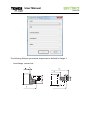
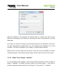
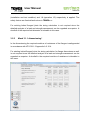
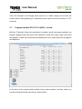
3.2
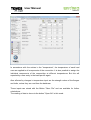
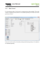
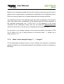
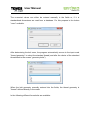
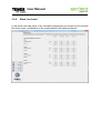
TEMESfl.cal input window – general information
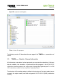
The user interface of the TEMESfl.cal – software is arranged in four areas:
•
•
•
•
Presets (1)
Selection of input masks (2)
Input fields of the selected input masks (3)
File management (4).
2
1
3
4
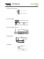
In the upper part of the left panel (area 1), the geometric designs of the flanges, the
bolts, the expansion sleeves and the seal of the selected method are defined:
Calculation methods:
At the moment KTA 3211.2 (Standard), KTA 3211.2
(MMC) and EN 1591 are available.
TEMES User Manual
Seite 12
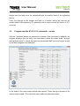
The following list shows all the parameters of the implemented methods of
calculation. The selections in the program parameters depend on the selected
method:
-
-
Flange type 1:
Loose flange conical neck
Loose flange with cylindrical neck
Loose flange cylindrical 1
Loose flange cylindrical 2
Hubbed threaded flange
Weld with conical neck
Weld-neck flange, conical shell 1
Weld-neck flange, conical shell 2
Weld-neck flange, conical shell 3
Slip-on-welding flange with neck
Weld-on plate flange
Weld-neck flange, cylindrical shell
Flange conical shell 1
Flange conical shell 2
Flange- spherical shell 1
Flange- spherical shell 2
Flange face 1:
type A (flat face)
type B (raised face)
type C (tongue)
type D (groove)
type E (spigot)
type F (recess)
type G (O-ring spigot)
type H (O- ring groove)
type I (RTJ-groove)
type J (chamfer)
(only KTA 3211.2 (KHS), EN 1591)
(only KTA 3211.2 (KHS)
(only EN 1591)
(only EN 1591)
(only EN 1591)
(only KTA 3211.2)
(only EN 1591)
(only EN 1591)
(only EN 1591)
(only EN 1591)
(only EN 1591)
(only EN 1591)
(only EN 1591)
(only EN 1591)
(only EN 1591)
TEMES User Manual
Seite 13
- flange type 2:
Same like flange type 1
additional:
symmetrical flange
blank flange
blank flange 1
blank flange 2
-
Flange face 2:
Like flange 1: flange face 2
-
Type of bolts:
screw
anti fatigue bolt
stud bolt
stud metal end
(only KTA 3211.2)
(only EN 1591)
(only EN 1591)
(only KTA 3211.2 )
-
Extension sleeve:
yes
no
-
Type of gasket:
Flat gasket (Form FF)
Type IBC- flat gasket
Non-metallic flat gasket (Form TG)
Non-metallic flat gasket (Form SR)
Rubber gasket with inserts
Sheet gasket with inner eyelet
Spiral wound gasket
Sheet gasket with PTFE- envelop
Metallic gasket with flat or corrugated profile (type SC)
Metallic gasket with flat or corrugated profile (type CR)
RTJ- gasket (oval type)
RTJ- gasket (octogonal type)
Kammprofile gasket
Metal jacketed gasket with layers
TEMES User Manual
Seite 14
In the header of the user interface (area 2) the tabs representing various input masks
are displayed. Tabs that are not required according to the preselections made in
area 1 are not displayed. If you miss a tab, please check preselections.
In the central region (region 3) of the user interface are the specific Input fields.
These tabs include drawings which illustrating the required data.
In all input masks there is the possibility to save the input data by clicking the button
"save record“ and selecting a drive, a folder and a file name. The stored data can be
read via the button “open data“ after selecting a drive, a folder and a file name.
Some of these input tabs are always available, while others are only displayed if the
corresponding preset value is selected. The tabs, which are always present, include:
-
general: In this tab can be entered general information for the flange calculation;
load: In this tab the temperature and pressure loads can be defined which will be
included in the calculation. Similarly, external loads can be defined;
flange 1: Depending on the type of flange appear different tabs to define the
flange geometry;
raised faces: Here the geometric dimension of the raised faces of the flanges
cam be entered;
bolts: Depending on the type of bolt different screens for defining the geometry of
the bolt will appear;
thread: Tab for entering the thread dimensions;
gasket geometry: Entering the gasket dimensions;
material of gasket: Tab for entering the required gasket characteristics;
flange 1 material: Entering the strength characteristics of the material for flange
1;
material of bolts: Entering the strength characteristics of the material for the
bolts;
assembly: Defining the assembly parameters.
Furthermore, additional tabs can be displayed, which shall also be completed:
-
Flange 2: If the geometries of the two flanges differ, these can be entered
separately.
TEMES User Manual
Seite 15
-
-
-
Flange 2 material: If the materials of the two flanges differ, these can be entered
separately.
Loose flange 1 material: is for flange 1 the type “loose flange” selected and the
material of the loose flange differs from stub/flare, these can be entered
separately.
Loose flange 2 material: is for flange 2 the type “loose flange” selected and the
material of the loose flange differs from stub/flare, these can be entered
separately.
Shell 1 material: Entering the strength characteristics of the material for shell 1
(only EN 1591).
Shell 2 material: Entering the strength characteristics of the material for shell 2
(only EN 1591).
Extension sleeve geometry: In these selection must be entered the geometry of
the expansion sleeves.
Extension sleeve material: In these selection must be entered the material of
the expansion sleeves.
In the lower left region of the window (area 4) several buttons are arranged to give
access to the following functions:
-
version: contains information about the installed versions of each TEMESfl.cal component ,
TEMES User Manual
Seite 16
-
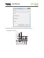
new: a new, empty file is created,
remark: a remark window opens to document important information about the
present calculation,
TEMES User Manual
Seite 17
-
calculation: the calculation can be started as soon as you have entered all
information,
TEMES User Manual
Seite 18
-
Save file: save file before a calculation starts,
TEMES User Manual
Seite 19
-
Open file: open an existing file,
-
Close: closes the program.
The following section 3.3 describes the main page of the TEMESfl.cal - presentation of
results.
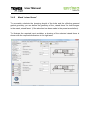
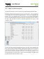
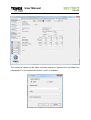
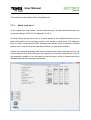
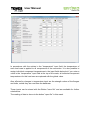
3.3
TEMESfl.cal – Results - General information
With the button “calculation“ in the input mask you can start the calculation. If all input
data is available, the calculation is performed and the program in the KTA 3211.2
calculation modules jumps to the output mask "strength and tightness proof" or in EN
1591 calculation module to the output tab "assembly value".
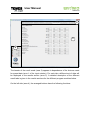
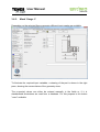
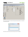
The structure of the results masks is similar to the structure of the input masks (as an
example, the output mask "proof bolt and gasket" of KTA 3211.2 (KHS) calculation
module).
TEMES User Manual
Seite 20
2
3
4
The header of the result mask (area 2) appears in dependence of the choices made
for preset data (area 1 of the input window). For each tab a different set of data will
be displayed in the results section (area 3). A detailed description of the different
result tabs is given in the results sections for the different program modules below.
On the left side (area 4), the arranged buttons have the following functions:
TEMES User Manual
Seite 21
-
remark: enter additional information about the current calculation (it is also
possible to print this information),
TEMES User Manual
Seite 22
-
save result: Saves the entire file, including the input values, calculation results
and the selected assembly requirements,
TEMES User Manual
Seite 23
-
print: With this button, the calculation data is sent to the configured default printer
or another printer installed. The scope (input, result) can be selected. If a PDF
writer is installed on the PC, the calculation can be saved as a pdf-file.
-
input mask: back to the input mask to modify input values or to change the
calculation method,
-
Close: Button, to close the software TEMESfl.cal or to change the calculation
method.
In the following chapters the different input masks will be described in detail in the
context of the chosen calculation method.
TEMES User Manual
Seite 24
3.4
Program module KTA 3211.2 (KHS) – user interface
This chapter describes the input masks of the program module KTA 3211.2 (KHS) in
detail.
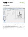
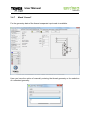
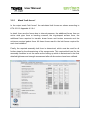
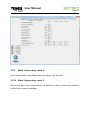
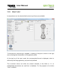
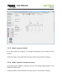
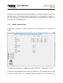
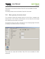
3.4.1
Mask “general“
In the mask „general“ you can enter information about the calculation which are seen
on the printout.
There are four panels for entering customer data, the name of the editor and the
auditor can be entered as well as the revision of the calculation. For a unique
assignment of the calculation to a flanged connection, a plant identifier, identification
code and a nomenclature (description) of the flange can be entered as alpha numeric
data.
TEMES User Manual
Seite 25
The logo of the customer you are making the calculation for must be in *.wmf-format
added in the installation folder of your TEMESfl.cal installation (e.g. D:\TEMES flcal
7.xx\logo.wmf).
For optimal viewing and logo quality, we recommend an aspect ratio of 1:3.
This logo is then automatically added to the calculation printout.
These inputs can be stored with the button "save file" and are available for further
calculations.
With the button "open file" you can fill in all input fields on this mask with predefined
values.
TEMES User Manual
Seite 26
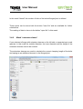
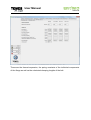
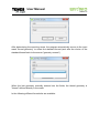
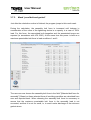
3.4.2
Mask “load “
In the mask "load" four load cases can be specified:
- assembly (assembly conditions, unpressurized, bolting torque)
- test condition (leak test)
- Operation 1 (eg normal operation)
- Operation 2 (eg operation with design conditions)
For each of the four load cases the loads temperature, internal pressure, external
axial force, shear force, external bending moment and torsional moment can be
defined. In the "transmission of shear forces" is specified whether these are
transmitted via interlocking or by friction.
In accordance with the entries in the "temperature" input field, the temperature of
each load case is applied to all components of the connection. It is also possible to
assign individual component temperatures in the input fields below but if you enter a
TEMES User Manual
Seite 27
value in the “temperature” input field at the top of the mask, all individual component
temperatures for this load case are replaced with the global value.
Also affected by changes in temperature input are the strength values of the flanges
and bolts, unless they are read from the database.
These inputs can be stored with the Button "save file" and are available for further
calculations.
The reading of data is done via the button "open file" in this mask.
TEMES User Manual
Seite 28
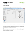
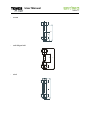
3.4.3
Mask “flange 1“
Depending on the selected flange geometry different input masks are available.
To illustrate the required input variables, a drawing of the part is displayed in the right
area, showing the nomenclature of the geometry sizes.
The numerical values can either be entered manually in the fields, or – if the
dimensions are defined in a standard – they can be read from a database. For this
purpose you find the button "code".
TEMES User Manual
Seite 29
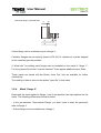
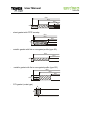
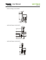
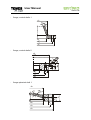
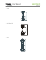
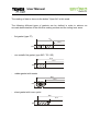
The following different geometrical shapes can be defined for flange 1:
loose flange, conical hub
i
SR
d2
d1
SF
dF
-
hL
hA
dL
hF
-
dt
TEMES User Manual
Seite 30
-
loose flange, cylindrical hub
d2
di
SR
hF
r
hl
dL
d1
dt
-
dF
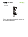
weld-neck flange, conical shell
R
A
i
F
F
dL
t
F
weld-neck flange, cylindrical shell
SR
di
hF
-
dt
dF
dL
TEMES User Manual
Seite 31
A blind flange can be modelled only as flange 2.
Container flanges are not explicitly listed in KTA 3211.2, therefore it must be adapted
to the model as good as possible.
A “blind hole” for welding neck flanges can be modelled on the mask of "flange 1".
For this purpose "blind hole" must be selected. With that selection additional input
fields will appear.
These inputs can stored with the Button "save file" and are available for further
calculations.
The reading of data is done via the button "open file" in this mask.
3.4.4
Mask “flange 2“
Essentially the input masks for flange 1 and 2 are identical and the input options are
the same. Following differences should be noted:
-
With the preselection "symmetrical flanges" you don’t need to enter the flange
geometry data for flange 2;
A blind hole can be modelled only in flange 1;
A blind flange must be modelled as flange 2.
TEMES User Manual
Seite 32
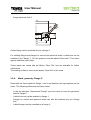
3.4.5
Mask “raised faces“
To accurately calculate the clamping length of the bolts and the effective pressed
gasket geometry you can define the geometry of the „raised faces“ for both flanges
in the mask „raised faces“ (if the selection has been made in the preset area before).
To illustrate the required input variables, a drawing of the selected raised faces is
shown with the required dimensions in the right area.
TEMES User Manual
Seite 33
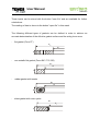
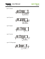
The following raised faces geometries are available:
-
type A (flat face)
-
type B (raised face)
f1
Ø d1
-
type C (tongue)
f2
f5
Øw
Øx
-
type D (groove)
f3
f1
Øz
Øy
Ø d1
-
type E (spigot)
f2
Øx
TEMES User Manual
Seite 34
-
type F (recess)
f3
f1
Øy
Ø d1
-
type G (O-Ring spigot)
f2
f1
-
Øw
Ø d1
type H (O-Ring groove)
R
f4
-
type I (RTJ- groove)
-
type J (chamfer)
f3
Øz
Øy
TEMES User Manual
Seite 35
After you have selected "symmetrical flange" in the dialog box "flange 2" and chosen
a raised face for this flange, the opposite side is automatically set to the raised face
that fits to flange 1. If this is not desired, an individual input must be done for
"flange 2".
Also, the gasket surfaces can be stored with the button "save record” and are
available for further calculations again. The reading of this data is done via the button
"open data" on the same mask.
On a blind flange it is important to ensure the correct entering of the raised face,
because the flange thickness of the central portion of the flange must be considered.
An additional input of a raised face (Form B) would mean in this case a too large
clamping length of the bolt. It is therefore recommended to select the raised face
“type A”.
TEMES User Manual
Seite 36
3.4.6
Mask “bolts“
Depending on the selected type of bolt various input masks are available:
To illustrate the required input variables, a drawing of the part is shown in the right
area, showing the nomenclature of the geometry sizes.
At the top line of the input mask, the recommended thread is displayed, which is
defined by the flange geometry previously defined.
The numerical values can either be entered manually in the fields or – if the
dimensions are defined in a standard – they can be read from a database. For this
purpose the button "code" is available.
TEMES User Manual
Seite 37
After determining the bolt, the program automatically moves to the input mask
"thread geometry" to select the standard thread (and after the choice of the standard
thread back to the screen "geometry screws").
When the bolt geometry is entered manually into the fields, the thread geometry is
defined directly in the mask.
TEMES User Manual
Seite 38
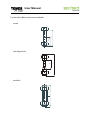
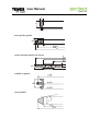
For the bolts different forms are available:
screw
-
anti fatigue bolt
-
stud bolt
l
ds
ls
lg
ls
-
TEMES User Manual
Seite 39
-
stud metal end
The input variables in the input mask "bolts" can be stored with the button „save
record“ and are available for further calculations again. The reading of data is done
via the button "open data" on the screen
TEMES User Manual
Seite 40
3.4.7
Mask “thread“
For the geometry data of the thread a separate input mask is available.
Here you have the option of manually entering the thread geometry or the selection
of a standard geometry.
TEMES User Manual
Seite 41
In this mask "thread" the number of bolts of the bolted flanged joint is defined.
These inputs can be stored with the button "save file" and are available for further
calculations.
The reading of data is done via the button "open file" in this mask.
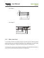
3.4.8
Mask “extension sleeve“
If you selected a flange with extension sleeves on the left side, a separate input mask
appears. In this mask the outside diameter, the inner diameter and the height of the
extension sleeves need to be entered.
The extension sleeves are used to calculate the correct clamping length of the bolts
and spring as an additional element in the flanged joint.
TEMES User Manual
Seite 42
These inputs can be stored with the button "save file" and are available for further
calculations.
The reading of data is done via the button "open file" in this mask.
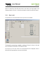
3.4.9
Mask “gasket geometry“
Depending on the selected flange geometry different input masks are available:
To illustrate the required input variables, a drawing of the gasket is shown in the right
area, showing the nomenclature of the dimensions:
The different gasket parameters can either be entered manually or, – if the
dimensions are defined in a standard – they can be read from a database. For this
purpose the button "code" is available.
TEMES User Manual
Seite 43
These inputs can be stored with the button "save file" and are available for further
calculations.
The reading of data is done via the button "open file" in this mask.
The following different types of gaskets can be defined in order to achieve an
accurate determination of the effective gasket surface and the acting lever arms:
-
flat gasket (Form FF)
da
di
h
-
non-metallic flat gasket (Form IBC / TG / SR)
da
di
h
-
rubber gasket with inserts
da
di
h
-
sheet gasket with inner eyelet
da
di
h
TEMES User Manual
Seite 44
-
spiral wound gasket
d3
d2
d1
d0
h
-
sheet gasket with PTFE envelop
d3
d2
d1
h
-
metallic gasket with flat or corrugated profile (type SC)
da
di
h
-
metallic gasket with flat or corrugated profile (type CR)
d3
d2
d1
h
-
RTJ-gasket (ovale type)
A
B
P
TEMES User Manual
Seite 45
-
RTJ-gasket (octogonal type)
A
H
P
C
-
kammprofile gasket
h
Ø d1
Ø d2
Ø d3
-
metall cased gasket with layers
d3
d2
d1
d0
h
-
welded lip gasket
-
lense gasket
TEMES User Manual
Seite 46
3.4.10
Mask “gasket material“
In the input mask "gasket material" the gasket characteristics are entered to DIN
28090-1.
Standard data are not available for the gasket characteristics or no longer reflect the
state of the art.
Gasket characteristics given from the manufacturers can be stored with the button
"save file" and are available for further calculations.
The reading of data is done via the button "open file" in this mask.
The gasket characteristics σVU/L and σBU/L which define the minimum required gasket
stress during assembly and during operation shall be specified depending on the
required tightness class.
In the software TEMESfl.cal the values for σBU/L are entered in the input field
"minimum gasket stress" for the test condition and load cond. 1/2.
TEMES User Manual
Seite 47
For the assembly condition the minimum gasket stress that is required to obtain the
target σBU/L during operation is entered in this field, not the minimum gasket stress
σVU/L.
The modulus of elasticity of the gasket is dependent on the previously applied
maximum gasket stress, from which the gasket is unloaded again.
In a first approximation, therefore, the modulus of elasticity of the gasket should be
determined from the minimum surface pressure that is required for σBU/L. If the first
calculation run reveals that a much higher gasket stress can be applied during
assembly, the modulus of elasticity should be adjusted and another calculation run
should be performed.
The creep of gasket Δ hD indicates the creeping of the gasket for the applied gasket
stress and temperature.
Thermal expansion coefficients are also not available for the gasket materials. The
default value is 10 • 10-6 1/K. As the gasket height normally is small compared to the
thickness of the flange ring this approximation is acceptable.
The coefficient of friction for the gasket material is required to calculate the additional
axial force needed to transmit shear forces and torsion moments. If no test results
are available the coefficient of friction can be defined according to KTA 3211.2 as
follows:
-
0.05 for gasket PTFE-based,
0.1 for graphite gaskets,
0.15 with metallic pads with a smooth surface and
0.25 with uncoated fiber based gaskets.
The safety coefficient used in the dimensioning calculation is set to 1.2.
TEMES User Manual
Seite 48
3.4.11
Mask “fl. 1 material“
In the input mask "fl. 1 material", the strength characteristics of the material used for
flange 1 or the stub/flare of a loose flange can be entered. At the same time can you
can choose the material for the other flange (flange 2, loose flange 1 / 2) if they are
made of a different one. Therefore you must click the corresponding check box
"separate material input of:" in the input mask.
The values can be entered manually or imported into the fields from a database. For
this purpose the "code" button is available.
TEMES User Manual
Seite 49
After the selection of the material via material name or number, the code can be
defined in a dialog box, and finally you can select the form of manufacture in a third
dialog box.
As long as you make no changes to this selected data from the database, the values
are also automatically updated when you are changing the temperature of a load
condition. This does not happen if you modify or enter the data manually.
Manual inputs can be stored with the button "save file" and are available for further
calculations again. The reading of data is done via the "open file" also on this mask.
3.4.12
Mask “loose flange 1 material“
For the material of loose flange 1, there are the same functions as for the material of
flange 1 available. To enable this input mask for the loose flange 1 you need to
activate „Separate material input for loose flange 1" in the mask “fl. 1 material“.
TEMES User Manual
Seite 50
3.4.13
Mask “fl. 2 material“
For the material of flange 2 there are the same functions as for the material of flange
1 available. To enable this input mask for flange 2, you need to activate „Separate
material input flange 2" in the mask “fl. 1 material“.
3.4.14
Mask “loose flange 2 material“
For the material of loose flange 2, there are the same functions as for the material of
flange 1 available. To enable this input mask for the loose flange 2, you need to
activate „Separate material input loose flange 2" in the mask “fl. 1 material“.
TEMES User Manual
Seite 51
3.4.15
Mask “material of bolts“
In the input mask "material of bolts" the strength characteristics of the material can be
entered.
It offers the same functionality like in the input mask “fl. 1 material” for the material of
flange 1.
3.4.16
Mask “material of extension sleeve“
In the input mask "material of extension sleeve", the strength characteristics of the
material can be entered.
It offers the same functionality like the input mask of the material of flange 1.
TEMES User Manual
Seite 52
3.4.17
Mask “assembly“
The last input mask contains the information that is necessary for the calculation of
the assembly requirements specifications, such as tightening device, scatter band of
the tightening and friction coefficients.
The tightening device can be selected from a drop down list. The associated
scattering values used to calculate the bolt force are provided in Annex C of
EN 1591-1.
Additional tightening devices with other scatter values can be stored as user records
with "save file" and are available for further calculations via the button "open file".
In the draft rule change proposal of KTA 3211.2 it is mentioned that the tightness
proof must be provided with the average computational bolt force, so that the
negative dispersion value ε1- can be set to "zero". The strength analysis of the
TEMES User Manual
Seite 53
flanges and the bolts must be considered with the scatter band of the tightening
device.
Verify the strength of the flanges and bolts is to exhibit, taking into account the
scatter band of the tightening. For assembly with a torque wrench the factor of "0.2"
is proven.
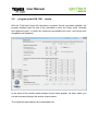
3.5
Program module KTA 3211.2 (standard) – results
With the "calculate" button the calculation is started. If all input data is available, the
program displays after the end of the calculation routine the output mask "strength
and tightness proof" in which the maximum permissible bolt force and torque as well
as the bolt elongation are displayed.
In the head of the result mask multiple tabs appear. These tabs give access to the
various output masks. The individual result masks are described below.
TEMES User Manual
Seite 54
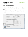
3.5.1
Mask “bolt forces“
In the output mask "bolt forces" the calculated bolt forces are shown according to
KTA 3211.2 Appendix A 2.9.4
In detail, there are the forces due to internal pressure, the additional forces from an
active axial pipe force or bending moment, the ring-shaped surface force, the
additional force required to transfer shear forces and torsion moments and the
minimum required gasket force. All these forces result in the bolt forces required for
each load condition.
Finally, the required assembly bolt force is determined, which must be used for all
further steps for the dimensioning of the components. This required bolt load for the
assembly condition is not the same as the bolting-up which is determined in the final
detailed tightness and strength assessment after all dimensions have been defined.
TEMES User Manual
Seite 55
For existing bolted flanged joints the sizing calculation is not required since the
detailed analysis of a leak and strength assessment can be regarded as superior. In
this case, the estimated assembly bolt force from the sizing calculation can be used
as initial value for the detailed proof.
3.5.2
Mask “dimensioning of bolts“
In the mask "dimensioning of bolts" the results for the dimensioning of the bolt are
shown:
The required bolt diameter is safeguarded according to KTA 3211.2 Appendix A
2.9.4.3.
To determine the allowable stress of the bolt material a safety factor of 1.1 (assembly
and test condition) and 1.5 (load cond. 1/2) respectively is applied for the
dimensioning of screw and studs. For all other types of bolts a safety factor of 1.3
TEMES User Manual
Seite 56
(installation and test condition) and 1.8 (operation 1/2) respectively is applied. The
safety factors are fixed default values in TEMESfl.cal.
For existing bolted flanged joints the sizing calculation is not required since the
detailed analysis of a leak and strength assessment can be regarded as superior. A
shortfall of the required bolt diameter is tolerable in this case.
3.5.3
Mask “fl. 1 dimensioning“
In the dimensioning the required modulus of resistance of the flanges is safeguarded
in accordance with KTA 3211.2 Appendix A 2.10.4.
For existing bolted flanged joints the sizing calculation for flange dimensions as well
is not required since the detailed analysis of a leak and strength assessment can be
regarded as superior. A shortfall in the required modulus of resistance is tolerable in
this case.
TEMES User Manual
Seite 57
For flanges with cylindrical neck the sections A-A (transition flange face to neck) and
C-C (in flange face) are evaluated. For flanges with conical neck the section B-B
(transition between neck and pipe) is evaluated as well. For loose flange joints the
loose flange itself is evaluated additionally.
For this purpose a modification to KTA 3211.2 is applied. The starting point of the
load transmission from the loose flange to the collar / raised edge is moved to the
outer edge of the collar / raised edge, reducing the lever arm to a value of a = aD. In a
strict approach to KTA 3211.2 the loose flanges are overloaded at relatively low
forces. FE analyses confirm this approach.
TEMES User Manual
Seite 58
3.5.4
Mask “fl. 2 dimensioning “
In the dimensioning of flange 2 the required modulus of resistance is safeguarded
according to KTA 3211.2 Appendix A 2.10.4. Apart from that the blind flange is
safeguarded according to KTA 3211.2 Appendix A 2.7.3.2.
For blind flanges the required thickness is safeguarded in the middle part of the
flange.
TEMES User Manual
Seite 59
3.5.5
Mask “proof bolt and gasket“
Just after the calculation routine is finished, the program displays this result mask.
During the calculation the assembly bolt force is increased until – under consideration
of the scatter due to the selected tightening device – one of the components has
reached 100% of its allowable stress. For this force, the associated bolt elongation
and the associated tightening torque are reported (in accordance with VDI 2230). At
the same time this force is held as a maximum permissible bolt force in load
conditions 1 and 2.
The user can now choose the assembly bolt force in the field "chosen assembly bolt
force" under the tab “assembly presetting”. Based on the selected force all results are
recalculated and reported. When choosing the assembly bolt force it is necessary to
ensure that the maximum allowable bolt force for the assembly condition is not
exceeded and that it is not too small in order to avoid unloading of the gasket down
to gasket stresses below the minimum value.
TEMES User Manual
Seite 60
Based on the “chosen assembly bolt force” the minimum and maximum bolt force or
gasket stress is determined under consideration of the scatter band of the tightening
device. The minimum gasket force and gasket stress respectively is used for the
tightness proof. The maximum bolt force and gasket force respectively is used for
stress analysis.
With the forces determined for assembly conditions the forces for all subsequent load
conditions are calculated. Therefore stiffness and thermal expansion of the individual
components are considered according to KTA 3211.2 2.10.6 Appendix A. The
minimum forces are used for the tightness proof and the maximum forces are used
for stress analysis.
In the detailed stress analysis for the bolts a safety factor of 1.1 is applied according
to KTA 3211.2 table 6.7-2 (no. 5: “… considering the tensioning condition”).
TEMES User Manual
Seite 61
3.5.6
Mask „stress analysis flange 1“
For the determined maximum forces in each condition the required moduli of
resistance are recalculated and safeguarded against the existing moduli of resistance
of the flanges.
For flanges with cylindrical neck the sections A-A (transition flange face to neck) and
C-C (in flange face) are evaluated. For flanges with conical neck the section B-B
(transition between neck and pipe) is evaluated as well. For loose flange joints the
loose flange itself is evaluated additionally.
For flanges at the tension protection during the detailed analysis according to KTA
3211.2 2.10-1 Table A ("considering the tension state ..." No. 4) always use a safety
facor of 1.1.
At small sizes (diameter ratio dF / di> 2) still takes a requirement for tension
reduction by a factor Φ, which is included in the software TEMESfl.cal
TEMES User Manual
Seite 62
If flange 1 is designed with a blind hole, the required depth is calculated according to
KTA 3211.2 Appendix A 2.9.4.4.2. There the stripping strength of the bolt thread, the
stripping strength of blind hole thread and adherence to a tried and tested criteria is
checked. Failure to meet any requirement of this limiting criterion is explicitly shown.
3.5.7
Mask “stress analysis flange 2“
The tension protection of flange 2 is the same lilke the protection of flange 1.
A special feature represents only the blind flange, which is regarded like the
dimensioning acc. to KTA 3211.2 Appendix A 2.7.3.2.
3.5.8
Mask “Intermediary result 1“
To make the calculation for the user easier to understand, various intermediate
results for flange 1 are shwon, such as the Φ- factor, or lever arms ort he distance of
their centres.
With the help of these intermediate results, it should be possible to verify individual
calculation steps. These intermediate results are also displayed on the printout of the
calculation.
TEMES User Manual
Seite 63
3.5.9
Mask “Intermediary result 2“
In this output mask, intermediate results for flange 2 are reported.
3.5.10
Mask “Intermediary result 3“
Also in this issue mask interim results are reported in order to make the calculation
for the user to easier understand.
TEMES User Manual
Seite 64
These are the thermal expansion, the spring constants of the individual components
of the flange as well as the calculated clamping lengths of the bolt.
TEMES User Manual
Seite 65
3.6.
Program module KTA 3211.2 (MMC) – user interface
This chapter describes the data input screens of the program module KTA 3211.2
(MMC).
3.6.1.
Mask “general“
In the mask "general" information can be saved for the calculation, and are also
displayed on the printout.
There are four panels for entering customer data, the name of the editor and the
auditor can be entered as the revision of the calculation. For uniquely assignment of
the calculation to a flange connection, a number of plant, plant identification and a
description of the flange can be entered.
TEMES User Manual
Seite 66
The logo of the customer for which you are making the calculation must be in *.wmfformat added in the installation folder of your "Temes.flcal.".
(D: \ TEMES flcal 7.0 \ logo.wmf)
For optimal viewing and logo quality, we recommend you an aspect ratio of 1:3.
This logo is then automatically added to the calculation printout.
These inputs can stored with the Button "Save File" and are available for further
calculations.
The reading of data is done via the button "Open file" in this mask.
3.6.2.
Mask “load“
In the mask "loads" are four load cases specified:
- assembly (assembly conditions, unpressurized, torque)
- test condition (leak test)
- Operation 1 (eg normal operation)
- Operation 2 (eg operation with design conditions)
For each of the four load cases the loads temperature, internal pressure, external
axial force, shear force, external bending moment and torsion moment can be
defined. In the "transmission of shear forces" is specified whether these are
transmitted via interlocking or by friction.
TEMES User Manual
Seite 67
In accordance with the entries in the "temperature", the temperature of each load
case are applied to all components of the connection. It is also possible to assign the
individual components of the composition at different temperatures. But this will
repealed by a new entry in the load-specific again.
Also affected by changes in temperature input are the strength values of the flanges
and bolts, unless they are read from the database.
These inputs can stored with the Button "Save File" and are available for further
calculations.
The reading of data is done via the button "Open file" in this mask.
TEMES User Manual
Seite 68
3.6.3.
Mask “flange 1“
Depending on the selected flange geometry different input masks are available.
To illustrate the required input variables, a drawing of the part is shown in the right
pane, showing the nomenclature of the geometry sizes..
The numerical values can either be entered manually in the fields or, if it is
standardized dimensions are read from a database. For this purpose is the button
"norm" available.
TEMES User Manual
Seite 69
Following different geometrical shapes can be defined for flange 1:
weld-neck flange, conical shell
R
A
i
F
F
-
dL
t
F
TEMES User Manual
Seite 70
-
weld-neck flange, cylindrical shell
SR
hF
di
dt
dL
dF
A blind flange can be modeled only as a flange 2.
Container flanges are not explicitly listed in KTA 3211.2, therefore it must be adapted
to the model as good as possible.
A “blind hole” for welding neck flanges can be modelled on the mask of "flange 1".
For this purpose "blind hole" must be selected. There appear additional input fields.
These inputs can stored with the Button "save File" and are available for further
calculations.
The reading of data is done via the button "open file" in this mask.
3.6.4.
Mask “flange 2“
Essentially the input masks for flange 1 and 2 are identical; the input options are the
same. The following differences should be noted:
- In the pre-selection "Symmetrical Flange" you don’t need to enter the geometric
data for flange 2
- A blind flange must be modelled as a flange 2.
TEMES User Manual
Seite 71
3.6.5.
Mask “raised faces“
To accurately calculate the clamping length of the bolts and the effective pressed
gasket geometry you can define the geometry of the „raised faces“ for both flanges
in the mask „raised faces“ (if earlier the selection made in the dialog boxes).
To illustrate the required input variables, a drawing of the selected raised faices is
shown with the required geometric quantities in the right area.
.
TEMES User Manual
Seite 72
The following raised faces geometries are available:
-
type A (flat face)
-
type B (raised face)
f1
Ø d1
-
TEMES User Manual
Seite 73
-
type C (tongue)
f2
f5
Øw
Øx
-
type D (groove)
f3
f1
Øz
Øy
Ø d1
-
type E (spigot)
f2
Øx
-
type F (recess)
f3
f1
Øy
Ø d1
-
type G (O-Ring spigot)
f1
f2
Øw
Ø d1
TEMES User Manual
Seite 74
-
type H (O-Ring groove)
R
f4
f3
Øz
Øy
After you select "symmetrical flange" in the dialog box "flange 2" and choosed a
raised face for this flange, the opposite side automatically select the the raised face
that fits to flange 1. If this is not desired, an individual input must be done for "flange
2"
Also, the sealing surfaces can stored with the button "save record” and are available
for further calculations again. The reading of this data is done via the button "open
data" on the same screen.
On a blind flange it is to ensure the correct entering of the raised face, because of the
flange thickness of the central portion of the flange must be considered. An additional
input of a raised face (Form B) would mean in this case a too large clamping length
of the bolt. It is therefore advisable to select the raised face type A.
TEMES User Manual
Seite 75
3.6.6.
Mask “bolts“
In dependence on the selected bolt various input forms are available.
To illustrate the required input variables, a drawing of the part is shown in the right
area, showing the nomenclature of the geometry sizes.
At the top line of the input mask, the recommended thread is displayed, which is
defined by the flange geometry you previously defined.
The numerical values can either be entered manually in the fields or, if it is
standardized dimensions are read from a database. For this purpose is the button
"norm" available.
TEMES User Manual
Seite 76
After determining the mounting screw, the program automatically moves to the input
mask "thread geometry" to select the standard thread (and after the choice of the
standard thread back to the screen "geometry screws").
When the bolt geometry manually entered into the fields, the thread geometry is
"thread" defined directly in the mask.
In the following different forms bolts are available:
TEMES User Manual
Seite 77
screw
-
anti-fatigue bolt
-
stud
l
ds
ls
lg
ls
-
TEMES User Manual
Seite 78
-
stud metal end
The input variables in the input mask "bolts geometry" can stored with the button
„save record“ and are available for further calculations again. The reading of data is
done via the button "open data" on the screen
TEMES User Manual
Seite 79
3.6.7.
Mask “thread“
For the geometry data of the thread is a separate input mask available. This mask
"thread" is skipped and the selection of a standard geometry for screws in the "bolts
geometry is shown."
Here you have the option of manually entering the thread geometry or the selection
of a standard geometry.
TEMES User Manual
Seite 80
In this screen, the number of bolts of the flange is defined.
TEMES User Manual
Seite 81
These inputs can stored with the Button "Save File" and are available for further
calculations.
The reading of data is done via the button "Open file" in this mask.
3.6.8.
Mask “geometry of extension sleeve“
If you selected a flange with extension sleeves on the left side, a separate entry
screen appears. In this mask the outside diameter, the inner diameter and the height
of the expansion sleeves need to be entered.
The expansion sleeves are used to calculate the correct clamping length of the bolts
and spring as an additional element in the flange.
These inputs can stored with the Button "Save File" and are available for further
calculations.
The reading of data is done via the button "Open file" in this mask.
TEMES User Manual
Seite 82
3.6.9.
Mask “gasket geometry“
Depending on the selected flange geometry different input masks are available:
To illustrate the required input variables, a drawing of the seal is shown in the right
area, showing the nomenclature of the geometry sizes:
The different gasket parameters can either be entered manually in the fields or, if it is
standardized dimensions are read from a database. For this purpose the button
"norm" is available.
These inputs can stored with the Button "Save File" and are available for further
calculations.
The reading of data is done via the button "Open file" in this mask.
TEMES User Manual
Seite 83
In this mask, the input for the diameter of the contact point of the power shunt takes
place.
The following different types of gaskets can be defined in order to achieve an
accurate determination of the effective sealing surface and the acting lever arms:
-
flat gasket (Form FF)
d G2
d G1
eG
-
non-metallic flat gasket (Form IBC / TG / SR)
d G2
d G1
eG
-
rubber gasket with inserts
d G2
d G1
eG
-
sheet gasket with inner eyelet
dG2
d G1
eG
-
spiral wound gasket
TEMES User Manual
Seite 84
d G3
d G2
d G1
dG0
eG
-
sheet gasket with PFTE envelop
d G3
d G2
d G1
eG
-
metallic gasket with flat or corrugated profile (type SC)
d G2
d G1
eG
-
metallic gasket with flat or corrugated profile (type CR)
d G3
d G2
dG1
eG
-
RTJ-gasket (ovale type)
A
B
P
TEMES User Manual
Seite 85
-
RTJ-gasket (octogonal type)
A
H
P
C
-
Kammprofile gasket
eG
Ø d G1
Ø d G2
Ø d G3
-
Metal jacketed gasket with layers
dG3
dG2
d G1
dG0
eG
-
Welded lip gasket
TEMES User Manual
Seite 86
3.6.10. Mask “gasket material“
In the input mask "gasket material" the gasket characteristics are entered to DIN
28090-1.
Standard Data are not available for the gasket characteristics or no longer reflect the
state of the art.
Gasket characteristics given from the manufacturers can stored with the Button
"Save File" and are available for further calculations.
The reading of data is done via the button "Open file" in this mask.
To achieve the leakage in a power shunt connection, a characteristic force is
required, which depends on the geometric relations between the gasket and the
groove in substantially. This force is always related to the gasket face and specified
as required gasket stress σKNS to meet the leakage.
TEMES User Manual
Seite 87
The creep of gasket Δ hD denotes the creeping of the gasket under the applied
strength under temperature.
Thermal expansion coefficients are also not available for the gasket materials. The
default value here, a value of 10 • 10-6 1 / K is attached. The usually small gasket
height compared to the thickness of the flangering, this approximation is acceptable.
The coefficient of friction for the gasket materials that will be needed to calculate the
additional axial force required to shear forces and torsional moments can be
transmitted by friction is, if no test results are available, to use of KTA 3211.2 as
follows:
-
0,05 for gasket PTFE-based,
0,1 for graphit gaskets,
0,15 with metallic pads with a smooth surface and
0,25 with uncoated fiber based gaskets.
The safety coefficient used in the dimensioning calculation is set to 1,2.
3.6.11. Mask “fl. 1 material“
In the input mask "Flange Material 1", the strength characteristics of the material
used for loose flange and flange 1 of the stub/flare can be entered. At the same time
can you can choose the material for the other flange (flange 2, loose flange 1 / 2) if
they are made of a different one. Therefore you must click "separate material input
for ....." in the input mask.
TEMES User Manual
Seite 88
The numerical values can be either manually entered or imported into the fields from
a database. For this purpose the button "norm" is available.
TEMES User Manual
Seite 89
After the selection of the material via material name or number, the code can be
defined in a dialog box, and finally you can select the form of manufacture in a third
dialog box.
As long you made no changes to this selected data from the database, the values
are also automatically updated when you are changing the temperature of a load
condition. This does not happen if you modified or entered the data manually.
Manual inputs can stored with the button "save file" and are available for further
calculations again. The reading of data is done via the "Open file" also on this mask.
3.6.12. Mask “fl. 2 material“
For the material of flange 2, there are the same functions as for the material of flange
1 available. To enable this input mask for the flange 2, you need to activate „separate
material input flange 2" in mask of „flange 1 material“.
TEMES User Manual
Seite 90
3.6.13. Mask “material of bolts“
In the input mask "bolt material", the strength characteristics of the material can be
entered.
It offers the same functionality like in the input screen of the material of flange 1.
3.6.14. Mask “material of extension sleeve“
In the input mask "material of extension sleeve", the strength characteristics of the
material can be entered.
It offers the same functionality like in the input screen of the material of flange 1.
TEMES User Manual
Seite 91
3.6.15. Mask “assembly“
The last input screen contains the information that are necessary for the calculation
of the assembly requirements specifications, such as tightening device, scatter band
of the tightening and friction coefficients.
The dialog box "assembly" are selectable various tightening devices. The associated
scattering values used to calculate the bolt force are provided in Annex C of EN
1591-1.
Additional tightening devices with other scatter values can stored as user records
with "save file" and are available for further calculations via the button "open file".
In the draft rule change proposal of KTA 3211.2 is mentioned, that the tightness proof
must be provided with the average computational bolt force, so that the negative
dispersion value ε1- can be set to "zero". The strength analysis of the flanges and the
bolts must be considered with the scatter band of the tightening device.
TEMES User Manual
Seite 92
Verify the strength of the flanges and screws is to exhibit, taking into account the
scatter band of the tightening. For assembly with a torque wrench the factor of "0.2"
is proven.
3.7.
Program module KTA 3211.2 (KNS) – results
With the "Calculate" button the calculation is started. Are all input data available, the
program displays after the end of the calculation routine the output mask "proof bolt
and gasket" in which the maximum permissible bolt force, and torque bolt elongation
are displayed.
In the head of the results mask multiple choice riders appear, via these riders you
can be accessed through the various output masks.
TEMES User Manual
Seite 93
The individual result tables will be described now:
3.7.1.
Mask “bolt force“
In the output mask "bolt forces" are the dimensioning of the bolt calculated forces are
shown according to KTA 3211.2 Appendix A 2.9.4
In detail, these are the force due to internal pressure, the additional forces from a
pipe acting axial force or bending moment, the annular surface force, the additional
force to shear forces and torsional moments can ablate and the minimum required
gasket force. As a result is the required bolt force for each load condition.
Finally, the required assembly bolt force is determined, which must be used for all
further steps for the dimensioning of the components. But this required bolt load for
the assembly condition is not the same as the bolting-up, which is determined when
detailed tightness and strength assessment.
TEMES User Manual
Seite 94
Principle can be dispensed with sizing calculation for existing compounds, since the
detailed analysis of a leak and strength assessment is to be regarded as superior. In
this case, the estimate assembly bolt force from the sizing calculation is used as a
benchmark for the detailed proof.
3.7.2.
Mask “dimensioning“
In the mask "dimension of bolts" the results of the dimensioning of the bolt are
shown:
The required bolt diameter is hedged according to KTA 3211.2 Appendix A 2.9.4.3.
To determine the allowable stress of the bolt material is in the dimensioning of screw
and studs, a safety factor of 1.1 (assembly and test condition) or 1.5 (load cond. 1/2)
TEMES User Manual
Seite 95
for all other types of bolts a safety factor of 1.3 (installation and test condition) or 1.8
(operation 1/2) applied. These values are stored within the program.
When sizing the required moment of resistance of the flanges is secured in
accordance with KTA 3211.2 Appendix A 2.10.4.
It is considered that there is no need for a sizing calculation for existing compounds,
since the detailed analysis of a leak and strength assessment is to be regarded as
superior. A shortfall of the required bolt diameter is tolerable in this case.
TEMES User Manual
Seite 96
3.7.3.
Mask “proof bolt and gasket“
Just after the calculation routine is finished, the program jumps to this result mask.
During the calculation, the assembly bolt force is increased until leakage in
consideration of the value of the tightening device is a capacity in a case of 100%
load. For this force, the associated bolt elongation and the associated torque are
reported (in accordance with VDI 2230). At the same time this power is held as a
maximum permissible bolt force in load conditions 1 and 2.
The user can now choose the assembly bolt force in the field "[Selected bolt force for
assembly"]. Based on these selected force all resulting quantities are calculated from
new and reported back. When choosing the assembly bolt force its necessary to
assure that the maximum permissible bolt force in the assembly load is not
exceeded, and that it is not too small, ie, to avoid undue discharge of the minimum
gasket stress.
TEMES User Manual
Seite 97
Based on the selected assembly bolt force the minimum and maximum bolt force or
gasket stress is determined by considering the scatter band of the tightening device.
With the minimum gasket force or gasket stress takes the tension protection..
The determined forces in the assembly state are under consideration of the tension
state, that means under considaration of the stiffness and the thermal expansion of
the individual components, acc. to KTA 3211.2 2.10.6 Appendix A, the forces
calculated for the subsequent states. Now you can make the leakproofness test
with the minimum force, and the proof of strength with the maximum force.
For the bolts in the detailed analysis of the tension protection according to KTA
3211.2 Table 6.7-2 (no.:5 "taking account to the tension state ..."), always use a
safety factor of "1.1":
3.7.4.
Mask “stress analysis flange 1”, “… flange 2“
For the determined maximum forces in every condition, the moments of resistance
getting calculated new and protected against the available moments of resistance of
the flange.
TEMES User Manual
Seite 98
TEMES User Manual
Seite 99
For flanges with a cylindrical neck of the section A-A (transition flange face to
approach), and the section C-C (in flange face) is always evaluated, wherein flanges
having a conical neck of the section B-B is considered (transition approach to the
tube). For loose flange connections nor the loose flange itself is secured beyond.
For flanges at the tension protection during the detailed analysis according to KTA
3211.2 2.10-1 Table A ("considering the tension state ..." No. 4) always use a safety
factor of 1.1.
At small sizes (diameter ratio dF / di> 2) still takes a requirement for tension
reduction by a factor Φ, which is included in the software TEMESfl.cal
If flange 1 is designed with a blind hole, the required depth is calculated according to
KTA 3211.2 Appendix A 2.9.4.4.2. There the stripping strength of the bolt thread, the
stripping strength of blind hole thread and adherence to a tried and tested criteria is
checked. Failure to meet any requirement of this limiting criterion is explicitly shown.
The tension protection of flange 2 is the same like the protection of flange 1.
A special feature represents only the blind flange, which is regarded like the
dimensioning acc. To KTA 3211.2 Appendix A 2.7.3.2.
TEMES User Manual
Seite 100
3.8.
Program module EN 1591 – user interface
This chapter describes the input screens of the program module EN 1591:
3.8.1.
Mask “general“
In the mask “general“ you can enter information about the calculation, see screenshot
below.
There are four input fields for customer data, fields for division, name, date and
signature of the editor in the column “calculated:” and the same four fields for the
auditor in the column “checked:” as well as the revision of the calculation. For a
unique assignment of the calculation to a flanged joint, a flange number, plant name,
identification code and a nomenclature (description) of the flange can be entered.
The logo of the customer you are making the calculation for must be in *.wmf-format
added in the installation folder of your TEMESfl.cal installation (e.g. D:\TEMES flcal
7.xx\logo.wmf).
TEMES User Manual
Seite 101
For optimal viewing and logo quality, we recommend an aspect ratio of 1:3.
This logo is then automatically added to the calculation printout.
These inputs can be stored with the button "save file" and are available for further
calculations.
With the button "open file" you can fill in all input fields on this mask with predefined
values.
3.8.2.
Mask “load“
In the mask "load" four load cases are specified:
- assembly (assembly conditions, unpressurized, bolting torque)
- test condition (leak test)
- Operation 1 (e.g. normal operation)
- Operation 2 (e.g. operation with design conditions)
For each of the four load cases the loads temperature, internal pressure, external
axial force and bending moment can be defined. The consideration of shear forces
and torsional moments is not possible in EN 1591-1.
TEMES User Manual
Seite 102
In accordance with the entries in the "temperature" input field, the temperature of
each load case is applied to all components of the connection. It is also possible to
assign individual component temperatures in the input fields below but if you enter a
value in the “temperature” input field at the top of the mask, all individual component
temperatures for this load case are replaced with the global value.
Also affected by changes in temperature input are the strength values of the flanges
and bolts, unless they are read from the database.
These inputs can be stored with the Button "save file" and are available for further
calculations.
The reading of data is done via the button "open file" in this mask.
TEMES User Manual
Seite 103
3.8.3.
Mask “flange 1“
Depending on the selected flange geometry different input masks are available.
To illustrate the required input variables, a drawing of the part is displayed in the right
area, showing the nomenclature of the geometry dimensions.
The numerical values can either be entered manually in the fields, or – if the
dimensions are defined in a standard – they can be read from a database. For this
purpose you find the button "code".
TEMES User Manual
Seite 104
The following different geometrical shapes can be defined for flange 1:
loose flange, conical hub
d6
b
es
d5
d0
d8
d3
d4
e
bF
bl
lH
-
TEMES User Manual
Seite 105
-
Loose flange, cylindrical hub 1
d6
bL
b0
d0
d8
d3
d4
-
bF
d5
es
Loose flange, cylindrical hub 2
d6
b0
d0
d8
d3
d4
d5
e1
hubbed threaded flange
es
e1
d GF2
d5
d0
d8
d3
d4
2*b F
d GF1
bL
-
bF
b
es
TEMES User Manual
Seite 106
-
weld-neck flange, conical shell 1
-
weld-neck flange, conical shell 2
e2
bF
l
es
d5
d0
d3
d4
weld-neck flange, conical shell 3
d1
s
H
1
F
-
d5
2
0
3
4
e2
TEMES User Manual
Seite 107
-
hubbed slip-on welded flange
bF
lH
es
d5
d0
d3
d4
-
e2
weld-on plate flange
bF
es
d5
d0
d3
d4
weld-neck flange, cylindrical shell
d1
lH
eS
bF
-
d5
d0
d3
d4
e2
TEMES User Manual
Seite 108
-
flange, conical shells 1
ds
bF
es
d0
d3
d4
-
flange, conical shells 2
-
flange spherical shell 1
d5
d0
d3
d4
d5
bF
bP
rK
es
ds
TEMES User Manual
Seite 109
-
flange spherical shell 2
ds
bF
d0
d3
d4
es
rk
s
bP
-
d5
A blind flange can be modeled only as a flange 2.
For welding flanges and flanges on conical and spherical shells, a blind hole can be
modeled in the "flange 1". For this purpose, must be labeled "blind hole." Then there
appear additional input fields.
These inputs can stored with the Button "Save File" and are available for further
calculations.
The reading of data is done via the button "Open file" in this mask.
3.8.4.
Mask „geometry Flange 2“
Essentially the input masks for flange 1 and 2 are identical; the input options are the
same. The following differences should be noted:
-
In the pre-selection "Symmetrical Flange" you don’t need to enter the geometric
data for flange 2,
A blind hole can just be modeled in flange 1,
Flanges on conical and spherical shells can also be modeled only as a flange
first,
A blind flange must be modelled as a flange 2.
TEMES User Manual
Seite 110
o blind flange 1
d9
d0
dX
d3
e0
e
eX
o blind flange 2
d5
d4
3.8.5.
Mask „raised faces“
To accurately calculate the clamping length of the bolts and the effective pressed
gasket geometry you can define the geometry of the „raised faces“ for both flanges
in the mask „raised faces“ (if earlier the selection made in the dialog boxes).
To illustrate the required input variables, a drawing of the selected raised faices is
shown with the required geometric quantities in the right area.
TEMES User Manual
Seite 111
The numerical values can either be entered manually in the fields or, if it is
standardized dimensions are read from a database. For this purpose is the button
"norm" available.
The following raised faces geometries are available:
-
-
type A (flat face)
TEMES User Manual
Seite 112
-
type B (raised face)
f1
Ø d1
-
type C (tongue)
f2
Øw
Øx
-
type D (groove)
f3
f1
Øz
Øy
Ø d1
-
type E (spigot)
f2
Øx
-
type F (recess)
f3
f1
Øy
Ø d1
TEMES User Manual
Seite 113
-
type G (O-Ring spigot)
f2
f1
-
Øw
Ø d1
type H (O-Ring groove)
R
f4
-
type I (RTJ- groove)
-
type J (chamfer)
f3
Øz
Øy
After you select "Symmetrical Flange" in the dialog box "flange 2" and choosed a
raised face for this flange, the opposite side automatically select the raised face that
fits to flange 1. If this is not desired, an individual input must be done for "flange 2"
Also, the sealing surfaces can stored with the button "save record and are available
for further calculations again. The reading of this data is done via the button "open
data" on the same screen.
On a blind flange it is to ensure the correct entering of the raised face, because of the
flange thickness of the central portion of the flange must be considered. An additional
TEMES User Manual
Seite 114
input of a raised face (Form B) would mean in this case a too large length of the
clamping lengths of the bolt. It is therefore advisable to select the raised face type A
3.8.6.
Mask „bolts“
In dependence on the selected bolt various input forms are available.
To illustrate the required input variables, a drawing of the part is shown in the right
area, showing the nomenclature of the geometry sizes.
At the top line of the input mask, the recommended thread is displayed, which is
defined by the flange geometry you previously defined.
TEMES User Manual
Seite 115
The numerical values can either be entered manually in the fields or, if it is
standardized dimensions are read from a database. For this purpose is the button
"norm" available.
After determining the bolt norm, the program automatically moves to the input mask
"thread geometry" to select the standard thread (and after the choice of the standard
thread back to the screen "geometry bolts").
When the bolt geometry manually entered into the fields, the thread geometry is
"thread" defined directly in the mask.
In the following different forms bolts are available:
TEMES User Manual
Seite 116
screw
-
anti-fatigue bolt
-
stud
l
ds
ls
lg
ls
-
TEMES User Manual
Seite 117
-
stud metal end
The input variables in the input mask "bolts geometry" can stored with the button
„save record“ and are available for further calculations again. The reading of data is
done via the button "open data" on the screen
3.8.7.
Mask „thread“
For the geometry data of the thread is a separate input mask available. This mask
"thread" is skipped and the selection of a standard geometry for bolts in the "bolts
geometry is shown."
TEMES User Manual
Seite 118
Here you have the option of manually entering the thread geometry or the selection
of a standard geometry.
In this screen, the number of bolts of the flange connection is defined.
TEMES User Manual
Seite 119
These inputs can stored with the Button "Save File" and are available for further
calculations.
The reading of data is done via the button "Open file" in this mask.
3.8.8.
Mask „geometry of extension sleeve“
If you selected a flange with extension sleeves on the left side, a separate entry
screen appears. In this mask the outside diameter, the inner diameter and the height
of the expansion sleeves need to be entered.
The expansion sleeves are used to calculate the correct clamping length of the bolts
and spring as an additional element in the flange.
These inputs can stored with the Button "Save File" and are available for further
calculations.
TEMES User Manual
Seite 120
The reading of data is done via the button "Open file" in this mask.
3.8.9.
Mask „gasket geometry“
Depending on the selected flange geometry different input masks are available:
To illustrate the required input variables, a drawing of the seal is shown in the right
area, showing the nomenclature of the geometry sizes:
The different gasket parameters can either be entered manually in the fields or, if it is
standardized dimensions are read from a database. For this purpose the button
"norm" is available.
These inputs can stored with the Button "save File" and are available for further
calculations.
TEMES User Manual
Seite 121
The reading of data is done via the button "Open file" in this mask.
The following different types of gaskets can be defined in order to achieve an
accurate determination of the effective sealing surface and the acting lever arms:
-
flat gasket (type FF)
d G2
d G1
eG
-
non-metallic flat gasket (type IBC / TG / SR)
d G2
d G1
eG
-
rubber gasket with inserts
d G2
d G1
eG
-
sheet gasket with inner eyelet
dG2
d G1
eG
TEMES User Manual
Seite 122
-
spiral wound gasket
d G3
d G2
d G1
dG0
eG
-
sheet gasket with PTFE envelop
d G3
d G2
d G1
eG
-
metallic gasket with flat or corrugated profile (type SC)
d G2
d G1
eG
-
metallic gasket with flat or corrugated profile (type CR)
d G3
d G2
dG1
eG
-
RTJ-gasket (ovale type)
A
B
P
-
RTJ-gasket (octagonal type)
TEMES User Manual
Seite 123
A
H
P
C
-
kammprofile gasket
eG
Ø d G1
Ø d G2
Ø d G3
-
metal jacketed gasket with layers
dG3
dG2
d G1
dG0
eG
-
welded lip gasket
-
lense gasket
TEMES User Manual
Seite 124
3.8.10. Mask „gasket material“
In the input mask "gasket material" the gasket characteristics are entered to DIN
28090-1.
Standard Data are not available for the gasket characteristics or no longer reflect the
state of the art.
Gasket characteristics given from the manufacturers can stored with the Button
"Save File" and are available for further calculations.
The reading of data is done via the button "Open file" in this mask.
Basically in 1591-1 shall be only use gasket characteristics determined according to
EN 13555. For this, the gasket manufacturer should be contacted.
TEMES User Manual
Seite 125
With the „CustomerDatabank“ you can add gasket characteristics manually to the
database.
Therefore you must open the “CustomerDatabase” in mask „gasket material“. Then
you go to „create data record“. You will find the database in the folder of your
TEMESfl.cal installation.
X:\TEMESflcal8.x\CustomerWerkstoffdatenbank.mdb
After opening the material database, you can record new characteristics with the
button „+“. Here you will be asked in the first mask to specify the type of gasket, the
gasket manufacturer and the gasket material.
In the following input masks you can define gasket characteristics as the minimum
and maximum required gasket stress, the thermal conductivity, the modulus of
elasticity and the PQR value depending on the temperature and the design pressure.
After entering the parameters, click on the "Accept" button and the data is stored in
the "Customer Material Database" and is available for any further calculation.
TEMES User Manual
Seite 126
3.8.11. Mask „flange 1 material“
In the input mask "Flange Material 1", the strength characteristics of the material
used for loose flange and flange 1 of the stub/flare can be entered. At the same time
can you can choose the material for the other flange (flange 2, loose flange 1 / 2) if
they are made of a different one. Therefore you must click "separate material input
for ....." in the input mask.
The values can be either manually entered or imported into the fields from a
database. For this purpose is the "norm" button available.
TEMES User Manual
Seite 127
After the selection of the material via material name or number, the code can be
defined in a dialog box, and finally you can select the form of manufacture in a third
dialog box.
As long you made no changes to this selected data from the database, the values
are also automatically updated when you are changing the temperature of a load
condition. This does not happen if you modified or entered the data manually.
Manual inputs can stored with the button "save file" and are available for further
calculations again. The reading of data is done via the "Open file" also on this mask.
3.8.12. Mask „loose flange 1 material“
For the material of loose flange 1, there are the same functions as for the material of
flange 1 available. To enable this input mask for the loose flange 1 you need to
activate „Separate material input for loose flange 1" in mask of „flange 1 material“.
TEMES User Manual
Seite 128
3.8.13. Mask „shell 1 material“
For the material of shell 1, the same functions as for the material of flange 1 are
available. To enable this input mask for shell 1, you need to enable "Separate input
material for shell 1" in mask of „material for flange 1“.
3.8.14. Mask „flange 2 material“
For the material of flange 2, there are the same functions as for the material of flange
1 available. To enable this input mask for the flange 2, you need to activate
„Separate material input flange 2" in mask of „flange 1 material“.
TEMES User Manual
Seite 129
3.8.15. Mask „loose flange 2 material“
For the material of loose flange 2, there are the same functions as for the material of
flange 1 available. To enable this input mask for the loose flange 2, you need to
activate „Separate material input loose flange 2" in mask of „flange 1 material“.
3.8.16. Mask „shell 2 material“
For the material of shell 2, the same functions as for the material of flange 1 are
available. To enable this input mask for shell 2, you need to enable "Separate input
material for shell 2" in mask of „material for flange 1“.
3.8.17. Mask „material of bolts“
In the input mask "bolt material", the strength characteristics of the material can be
entered.
It offers the same functionality like in the input screen of the material of flange 1.
3.6.16. Mask „material of extension sleeve“
In the input mask "material of extension sleeve", the strength characteristics of the
material can be entered.
It offers the same functionality like in the input screen of the material of flange 1.
3.8.18. Mask „assembly“
The last input screen contains the information that are necessary for the calculation
of the assembly requirements specifications, such as tightening device, scatter band
of the tightening and friction coefficients.
TEMES User Manual
Seite 130
The dialog box "assembly" are selectable various tightening devices. The associated
scattering values used to calculate the bolt force are provided in Annex C of EN
1591-1.
Additional tightening devices with other scatter values can stored as user records
with "save file" and are available for further calculations via the button "Open file" .
TEMES User Manual
Seite 131
3.9.
program modul EN 1591 - results
With the "Calculate" button the calculation is started. Are all input data available, the
program displays after the end of the calculation routine the output mask "strength
and tightness proof" in which the maximum permissible bolt force, and torque bolt
elongation are displayed.
In the head of the results mask multiple choice riders appear, via these riders you
can be accessed through the various output masks.
The individual result tables will be described now:
TEMES User Manual
Seite 132
3.9.1.
Mask „axial compliance“
In the mask „axial compliance“ you can see the effective gasket geometry, which
results from the flange rotation.
Also in this screen you can see the elasticity’s of the individual components, which
are needed to determine the compliances between the various loads. These axial
compliances under the loads gasket force, axial force of the media pressure and
external force are also given.
TEMES User Manual
Seite 133
3.9.2.
Mask „limits“
In the mask „limits“ there are given the minimum required forces to reach the
tightness requirements. Out of this results from each load condition, you can
calculate backwards the assembly bolt force you need to select, so that you don’t
drop below the minimum required gasket stress.
TEMES User Manual
Seite 134
3.9.3.
Mask „assembly presetting“
In this screen, first the required assembly bolt force to maintain the tightness
requirements and the maximum force to meet the strength requirements are
reported. The user can choose the assembly bolt force in “chosen assembly bolt
force”.
Then the corresponding torque and the bolt elongation are shown as default for the
assembly of these selected forces. Also the bolt force, the gasket force and the
gasket stress are reported for all loads, in each case taking into account the scatter
band of tightening.
TEMES User Manual
Seite 135
3.9.4.
Mask „load ratio“
In this mask, the load ratios of the individual components are shown for the selected
bolt force under consideration of the scatter band of the tightening device.
TEMES User Manual
Seite 136
Appendix
A.1. principles Norm KTA 3211.2
refer to:
KTA 3211.2
Draft rule change proposal
Version March 2003
A.2. priniciples Norm EN 1591
refer to:
EN 1591
Version Februar 2013
A.3. Rules and Standards
The calculation Software TEMES fl.cal accesses on a variety of standards:
- A.3.1 geometry standards
A.3.1.1 gaskets
A.3.1.2 flanges
A.3.1.3 bolts
- A.3.2 material standards
Below those are listed in a table:
TEMES User Manual
Seite 137
A.3.1.1 Standards for the gasket geometry
Standard
EN 1514-1:1997 Form FF
DIN 2690:1966
Typ
Flat gasket DIN flanges PN1-PN40
DIN 2691:1971
Flat gasket DIN flanges PN10-PN160
DIN 2692:1966
Flat gasket DIN flanges PN10-PN100 mit Vor- und Rücksprung
DIN 2697
EN 1514-1:1997 Form IBC
EN 1514-1:1997 Form TG
EN 1514-1:1997 Form SR
EN 1514-2:2005
Groove gasket
EN 1514-3:1997
Sheet gasket with PTFE envelop
EN 1514-4:1997
Metallic gasket with flat or corrugated profile
EN 1514-6:2003
EN 1514-7:2004 Form C/O oder C/IO
EN 1514-7:2004 Form SC oder C/I
DIN EN 125606:2004
Werknorm 104 für
DIN Flansche
Werknorm 188 für
DIN Flansche
Werknorm 101 für
DIN Flansche
Werknorm 145 für
DIN Flansche
WN-41-32 für
Wellringdichtung
WD12 (Rev. 1)
Kammprofile gasket
Full Face Gasket
Flat gasket
Flat gasket tongue / groove
Flat gasket male-/female
Spiral Wound gasket
Metallic gasket
Metallic gasket
Kammprofile gasket
Werknorm 104 für DIN flanges
Werknorm 188 für DIN flanges
Werknorm 101 für DIN flanges
Werknorm 145 für DIN flanges
WN-41-32 für Wellringdichtung WD12 (Rev. 1)
TEMES User Manual
Seite 138
A.3.1.2 Standards for the flange geometry
Standard
DIN 2527:1972
DIN 2532:1976
DIN 2533:1976
DIN 2534:1967
DIN 2535:1967
DIN 2543:1977
DIN 2544:1977
DIN 2545:1977
DIN 2546:1969
DIN 2548:1969
DIN 2549:1969
DIN 2550:1969
DIN 2551:1969
DIN 2566:1975
DIN 2568
DIN 2569
DIN 2573:1975
DIN 2576:1975
DIN 2627:1975
DIN 2628:1975
DIN 2629:1975
DIN 2630:1975
DIN 2631:1975
DIN 2632:1975
DIN 2633:1975
DIN 2634:1975
DIN 2635:1975
DIN 2636:1975
DIN 2637:1975
DIN 2638:1975
DIN 2652
DIN 2653
DIN 2655
DIN 2656
DIN 2673:1962
DIN 2674:1974
DIN 2675:1979
DIN 2676:1978
DIN 28115:2003
DIN 28117:1990
DIN 86029:1987
Typ
Blank flange
weld-neck flange
weld-neck flange
weld-neck flange
weld-neck flange
Cast steel flanges
Cast steel flanges
Cast steel flanges
Cast steel flanges
Cast steel flanges
Cast steel flanges
Cast steel flanges
Cast steel flanges
Threaded flange with neck
Threaded flange with neck
Threaded flange with neck
Weld-on plate flange
Weld-on plate flange
weld-neck flange
weld-neck flange
weld-neck flange
weld-neck flange
weld-neck flange
weld-neck flange
weld-neck flange
weld-neck flange
weld-neck flange
weld-neck flange
weld-neck flange
weld-neck flange
Loose flange, plain collars
Loose flange, plain collars
Loose flange, plain collars
Lose Flansche, plain collars
Loose flange with welding end
Loose flange with welding end
Loose flange with welding end
Loose flange with welding end
Flange outlets
Block flange
Welding flange with neck
TEMES User Manual
Seite 139
A.3.1.2 Standards for the flange geometry
DIN 86030:1987
EN 1092-1:2008
EN 1092-1:2008
EN 1092-1:2008
EN 1092-1:2008
EN 1092-1:2008
EN 1092-1:2008
EN 1092-1:2008
EN 1092-1:2008
EN 1092-1:2008
Typ
Welding flange with neck
Typ 01 flat welding flange
Typ 05 blank flange
Typ 11 weld-neck flange
Typ 12 hubbed slip-on weleded flange
Typ 13 hubbed threaded flange
Typ 21
Typen 02 und 32 Loose flange, plain collars
Typen 02 und 33 Loose flange for beaded pipes
Typen 02 und 35 Loose flange with welded ring
EN 1092-1:2008
Typen 02 und 36 Loose flange with long neck
EN 1092-1:2008
EN 1092-1:2008
EN 1092-2:1997
EN 1092-2:1997
EN 1092-2:1997
prEN 1092-1:1994
prEN 1092-1:2005
prEN 1092-1:2005
prEN 1092-1:2005
prEN 1092-1:2005
Typen 02 und 37 Loose flange für Pressbördel
Typen 04 und 34 Loose flange for welded necks
Typ 21 ductile cast iron (DG)
Typ 21 gray cast iron (GG)
Typ 21 malleable iron (TG)
Steel flange
Typ 01 welding plain flange
Typ 05 blank flange
Typ 11 weld-neck flange
Typen 02 und 35 Loose flange with welded ring
prEN 1092-1:2005
Typen 02 und 36 Loose flange with long neck
prEN 1092-1:2005
prEN 1092-1:2005
prEN 1092-2:1993
prEN 1092-3:1994
prEN 1092-4:1995
Typen 02 und 37 Loose flange für Pressbördel
Typen 04 und 34 loose flange for welded necks
Cast iron flanges
Flanges (copper alloy and compoiste materials)
Flanges (aluminium alloy)
Standard
TEMES User Manual
Seite 140
A.3.1.2 Standards for the flange face geometry
Standard DIN 2512:1975
DIN 2513:1966
DIN 2514:1975
DIN 2527:1972
DIN 2532:1976
DIN 2533:1976
DIN 2534:1967
DIN 2535:1967
DIN 2543:1977
DIN 2544:1977
DIN 2545:1977
DIN 2546:1969
DIN 2548:1969
DIN 2549:1969
DIN 2550:1969
DIN 2551:1969
DIN 2566:1975
DIN 2627:1975
DIN 2628:1975
DIN 2629:1975
DIN 2630:1975
DIN 2631:1975
DIN 2632:1975
DIN 2633:1975
DIN 2634:1975
DIN 2635:1975
DIN 2636:1975
DIN 2637:1975
DIN 2638:1975
DIN 28115:2003
EN 1092-1:2008
prEN 1092-1:2005
Typ Tongue / groobe
Male / female
Male / female
Blank flanges – nominal oressure 6 bis 100
Cast iron flanges, nominal pressure 10
Cast iron flanges, nominal pressure 16
Cast iron flanges, nominal pressure 25
Cast iron flanges, nominal pressure 40
Cast steel flanges, nominal pressure 16
Cast steel flanges, nominal pressure 25
Cast steel flanges, nominal pressure 40
Cast steel flanges, nominal pressure 64
Cast steel flanges, nominal pressure 160
Cast steel flanges, nominal pressure 250
Cast steel flanges, nominal pressure 320
Cast steel flanges, nominal pressure 400
Hubbed threaded flange PN 6, 10, 16, 25, 40
Weld-neck flanges, nominal pressure 400
Weld-neck flanges, nominal pressure 250
Weld-neck flanges, nominal pressure 320
Weld-neck flanges, nominal pressure 1 und 2.5
Weld-neck flanges, nominal pressure 6
Weld-neck flanges, nominal pressure 10
Weld-neck flanges, nominal pressure 16
Weld-neck flanges, nominal pressure 25
Weld-neck flanges, nominal pressure 40
Weld-neck flanges, nominal pressure 64
Weld-neck flanges, nominal pressure 100
Weld-neck flanges, nominal pressure 160
Flange connector, nominal pressure 10
Round steel flanges
Round steel flanges
TEMES User Manual
Seite 141
A.3.1.3 Standards for the bolt geometry
Typ
Anti-fatigue bolt
Anti-fatigue bolt
Anti-fatigue bolt
Anti-fatigue bolt
Anti-fatigue bolt
Anti-fatigue bolt
Anti-fatigue bolt
Anti-fatigue bolt
Anti-fatigue bolt
Anti-fatigue bolt
Stud bolt
screw
screw
screw with shaft
screw with shaft
screw
screw
screw
Standard
DIN 2510:1971, Bl. 3, Form K
DIN 2510:1971, Bl. 3, Form KU
DIN 2510:1971, Bl. 3, Form L
DIN 2510:1971, Bl. 3, Form Z
DIN 2510:1971, Bl. 4, Form G
DIN 2510:1971, Bl. 4, Form H
DIN 2510:1971, Bl. 4, Form P
DIN 2510:1971, Bl. 4, Form Q
DIN 2510:1971, Bl. 4, Form R
DIN 2510:1971, Bl. 4, Form S
DIN 2509:1970
DIN 931:1970
DIN 933:1970
EN ISO 4014:2001, Produktklasse A
EN ISO 4014:2001, Produktklasse B
DIN 938:1995
DIN 939:1995
DIN 940:1995
A.3.1.3 Standards for the thread geometry
Typ
Standard
Metrical thread with large match
DIN 2510:1971, Bl. 2
Metrical ISO-thread regular thread
DIN 13:1986
A.3.1.3 Standards for the extension sleeve geometry
Standard
DIN 126:1990
DIN 2510:1971 - Form D
DIN 2510:1971 - Form E
A.3.1.3 Standards for the nut geometry
Standard
ASME B18.2.2:2010
DIN 2510:1971, Bl. 5
EN ISO 4032:2000
TEMES User Manual
Seite 142
A.3.2 material standards
Standard
material
AD W3/2
AD W3/2
AD W3/2
AD W3/2
AD W3/2
AD W3/2
AD W3/2
AD W3/2:2000
AD W3/2:2000
AD W3/2:2000
AD W3/2:2000
AD W3/2:2000
AD W3/2:2000
DIN 1691:1985
DIN 1691:1985
DIN 1691:1985
DIN 1691:1985
DIN 1691:1985
DIN 17100
DIN 17100
DIN 17100
DIN 17100
DIN 17100 ADW13:1980
DIN 17103:1989
DIN 17103:1989
DIN 17155:1983
DIN 17155:1983
DIN 17155:1983
DIN 17155:1983
DIN 17155:1983
DIN 17155:1983
DIN 17155:1983
DIN 17155:1983
DIN 17173:1985
DIN 17173:1985
DIN 17175:1979
DIN 17175:1979
DIN 17175:1979
DIN 17175:1979
DIN 17175:1979
GG-25
GGG-35.3
GGG-40 (0.7040)
GGG-40.3
GGG-50 (0.7050)
GGG-60 (0.7060)
GGG-70 (0.7070)
EN-GJS-350-22
EN-GJS-400-15
EN-GJS-400-18
EN-GJS-500-3
EN-GJS-600-3
EN-GJS-700-2
GG-15
GG-20
GG-25
GG-30
GG-35
RSt 37-2 (1.0038)
ST 37.3 (1.0116)
St 37-2 (1.0037)
USt 37-2 (1.0036)
St 52-3 (1.0570)
StE 355 (1.0562)
WStE 355 (1.0565)
10CrMo9-10 (1.7380)
13CrMo4-4 (1.7335)
15Mo3 (1.5415)
17Mn4 (1.0481)
19Mn6 (1.0473)
H I (1.0345)
H II (1.0425)
UH I (1.0348)
TTSt 35 N (1.0356)
TTSt 35 V (1.0356)
10CrMo9-10 (1.7380)
13CrMo4-4 (1.7335)
14MoV6-3 (1.7715)
15Mo3 (1.5415)
17Mn4 (1.0481)
TEMES User Manual
Seite 143
A.3.2 material standards
Standard
DIN 17175:1979
DIN 17175:1979
DIN 17175:1979
DIN 17175:1979
DIN 17177:1979
DIN 17177:1979
DIN 17177:1979
DIN 17240
DIN 17240
DIN 17240
DIN 17240
DIN 17240
DIN 17240
DIN 17240
DIN 17240:1959
DIN 17240:1976
DIN 17240:1976
DIN 17240:1976
DIN 17240:1976
DIN 17243:1979
DIN 17243:1979
DIN 17243:1979
DIN 17243:1979
DIN 17243:1979
DIN 17243:1979
DIN 17243:1979
DIN 17243:1979
DIN 17243:1987
DIN 17440:1985
DIN 17440:1985
DIN 17440:1985
DIN 17440:1985
DIN 17440:1985
DIN 17440:1985
DIN 17440:1985
DIN 17440:1985
DIN 17440:1985
DIN 17440:1985
DIN 17440:1985
DIN 17440:1985
material
19Mn5 (1.0482)
St 35.8 (1.0305)
St 45.8 (1.0405)
X20CrMoV12-1 (1.4922)
15Mo3 (1.5415)
St 37.8 (1.0315)
St 42.8 (1.0498)
40CrMo5 (1.7711)
C 35 (1.0501)
Ck 35 (1.1181)
Cq 35 (1.1172)
NiCr20TiAl (2.4952)
X19CrMoVNbN11-1 (1.4913)
X8CrNiMoBNb16-16 (1.4986)
24 CrMoV 5 5 (1.7733)
21CrMoV5-7 (1.7709)
24CrMo5 (1.7258)
34CrNiMo6S (1.6589)
X22CrMoV12-1 (1.4923)
10CrMo9-10 (1.7380)
14MoV6-3 (1.7715)
15Mo3 (1.5415)
17Mn4 (1.0481)
20Mn5 N (1.1133)
20Mn5 V (1.1133)
C 22.8 (1.0460)
X20CrMoV12-1 (1.4922)
13CrMo4-4 (1.7335)
X10Cr13 (1.4006)
X15Cr13 (1.4024)
X2CrNi19-11 (1.4306)
X2CrNiMo17-13-2 (1.4404)
X2CrNiMo18-14-3 (1.4435)
X2CrNiMo18-16-4 (1.4438)
X2CrNiMoN17-12-2 (1.4406)
X2CrNiMoN17-13-3 (1.4429)
X2CrNiMoN17-13-5 (1.4439)
X2CrNiN18-10 (1.4311)
X5CrNi18-10 (1.4301)
X5CrNi18-12 (1.4303)
TEMES User Manual
Seite 144
A.3.2 material standards
Standard
DIN 17440:1985
DIN 17440:1985
DIN 17440:1985
DIN 17440:1985
DIN 17440:1985
DIN 17440:1996
DIN 17440:1996
DIN 17440:1996
DIN 17440:1996
DIN 17440:1996
DIN 17440:1996
DIN 17441:1997
DIN 17441:1997
DIN 17441:1997
DIN 17445:1984
DIN 17445:1984
DIN 17445:1984
DIN 17445:1984
DIN 17445:1984
DIN 17445:1984
DIN 17445:1984
DIN 17445:1984
DIN 17445:1984
DIN 17457:1985
DIN 17457:1985
DIN 17457:1985
DIN 17458:1985
DIN 17458:1985
DIN 17458:1985
DIN 17458:1985
DIN 2528
DIN 2528
DIN EN 10025 & AD W13:1994
DIN EN 10025 & AD W13:1994
DIN EN 10025 & AD W13:1994
DIN EN 10025 & AD W13:1994
DIN EN 10025 ADW1:1994
DIN EN 10025 ADW1:1994
DIN EN 10028-2:1993
DIN EN 10028-2:1993
material
X5CrNiMo17-12-2 (1.4401)
X5CrNiMo17-13-3 (1.4436)
X6Cr13 (1.4000)
X6CrAl13 (1.4002)
X6CrNiTi18-10 (1.4541)
X17CrNi16-2 (1.4057, X20CrNi17-2)
X20Cr13 (1.4021)
X6CrNiMoNb17-12-2 (1.4580)
X6CrNiMoTi17-12-2 (1.4571)
X6CrNiNb18-10 (1.4550)
X6CrNiTi18-10 (1.4541)
X6CrNiMoTi17-12-2 (1.4571)
X6CrNiNb18-10 (1.4550)
X6CrNiTi18-10 (1.4541)
GX20Cr14 (1.4027)
GX22CrNi17 (1.4059)
GX3CrNiMoN17-13-5 (1.4439)
GX5CrNi13-4 (1.4313)
GX5CrNiMoNb18-10 (1.4581)
GX5CrNiNb18-9S (1.4552)
GX6CrNi18-9 (1.4308)
GX6CrNiMo18-10 (1.4408)
GX8CrNi13 (1.4008)
X6CrNiMoTi17-12-2 (1.4571)
X6CrNiNb18-10 (1.4550)
X6CrNiTi18-10 (1.4541)
X6CrNiMoNb17-12-2 (1.4580)
X6CrNiMoTi17-12-2 (1.4571)
X6CrNiNb18-10 (1.4550)
X6CrNiTi18-10 (1.4541)
15Mo3 (1.5415)
C 22.8 (1.0460)
S235J2G4 (1.0117)
S235JRG1 (1.0116)
S235JRG2 (1.0038)
S355J2G4 (1.0577)
S235J2G3 (1.0116, St37.3)
S235JRG2 (1.0038, RSt 37-2)
10CrMo9-10 (1.7380)
13CrMo4-5 (1.7335, 13CrMo4-4)
TEMES User Manual
Seite 145
A.3.2 material standards
Standard
DIN EN 10028-2:1993
DIN EN 10028-2:2003
DIN EN 10028-2:2003
DIN EN 10028-2:2003
DIN EN 10028-2:2003
DIN EN 10028-2:2003
DIN EN 10028-2:2003
DIN EN 10028-2:2003
DIN EN 10028-2:2003
DIN EN 10028-2:2003
DIN EN 10028-2:2003
DIN EN 10028-2:2003
DIN EN 10028-2:2003
DIN EN 10028-2:2003
DIN EN 10028-2:2003
DIN EN 10028-2:2003
DIN EN 10028-2:2003
DIN EN 10028-2:2003
DIN EN 10028-2:2003
DIN EN 10028-2:2003
DIN EN 10028-2:2003
DIN EN 10028-2:2003
DIN EN 10028-2:2009
DIN EN 10028-2:2009
DIN EN 10028-2:2009
DIN EN 10028-2:2009
DIN EN 10028-2:2009
DIN EN 10028-2:2009
DIN EN 10028-2:2009
DIN EN 10028-2:2009
DIN EN 10028-2:2009
DIN EN 10028-2:2009
DIN EN 10028-2:2009
DIN EN 10028-2:2009
DIN EN 10028-2:2009
DIN EN 10028-2:2009
DIN EN 10028-2:2009
DIN EN 10028-2:2009
DIN EN 10028-2:2009
DIN EN 10028-3:1993
material
16Mo3 (1.5415, 15Mo3)
10CrMo9-10 (1.7380)
12CrMo9-10 (1.7375)
12CrMoV12-10 +NT (1.7767)
12CrMoV12-10 +QT (1.7767)
13CrMo4-5 (1.7335)
13CrMoSi5-5 +NT (1.7336)
13CrMoSi5-5 +QT (1.7336)
13CrMoV9-10 +NT (1.7703)
13CrMoV9-10 +QT (1.7703)
15NiCuMoNb5-6-4 (1.6368)
16Mo3 (1.5415)
18MnMo4-5 (1.5414)
20MnMoNi4-5 (1.6311)
P235GH (1.0345)
P265GH (1.0425)
P265GH (1.0425, H II)
P295GH (1.0481)
P355GH (1.0473)
X10CrMoVNb9-1 (1.4903)
X12CrMo5 +NT (1.7362)
X12CrMo5 +QT (1.7362)
10CrMo9-10 (1.7380)
12CrMo9-10 (1.7375)
12CrMoV12-10 (1.7767)
13CrMo4-5 (1.7335)
13CrMoSi5-5 + NT (1.7336 + NT)
13CrMoSi5-5 + QT (1.7336 + QT)
13CrMoV9-10 (1.7703)
15NiCuMoNb5-6-4 (1.6368)
16Mo3 (1.5415)
18MnMo4-5 (1.5414)
20MnMoNi4-5 (1.6311)
P235GH (1.0345)
P265GH (1.0425)
P295GH (1.0481)
P355GH (1.0473)
X10CrMoVNb9-1 (1.4903)
X12CrMo5 (1.7362)
P275NH (1.0487, WStE 285)
TEMES User Manual
Seite 146
A.3.2 material standards
Standard
DIN EN 10028-3:1993
DIN EN 10028-3:1993
DIN EN 10028-3:2003
DIN EN 10028-3:2003
DIN EN 10028-3:2003
DIN EN 10028-3:2003
DIN EN 10028-3:2003
DIN EN 10028-3:2003
DIN EN 10028-3:2003
DIN EN 10028-3:2003
DIN EN 10028-3:2003
DIN EN 10028-3:2003
DIN EN 10028-3:2009
DIN EN 10028-3:2009
DIN EN 10028-3:2009
DIN EN 10028-3:2009
DIN EN 10028-3:2009
DIN EN 10028-3:2009
DIN EN 10028-3:2009
DIN EN 10028-3:2009
DIN EN 10028-3:2009
DIN EN 10028-3:2009
DIN EN 10028-4:2003
DIN EN 10028-4:2003
DIN EN 10028-4:2003
DIN EN 10028-4:2003
DIN EN 10028-4:2003
DIN EN 10028-4:2003
DIN EN 10028-4:2003
DIN EN 10028-4:2003
DIN EN 10028-4:2003
DIN EN 10028-4:2009
DIN EN 10028-4:2009
DIN EN 10028-4:2009
DIN EN 10028-4:2009
DIN EN 10028-4:2009
DIN EN 10028-4:2009
DIN EN 10028-4:2009
DIN EN 10028-4:2009
DIN EN 10028-4:2009
material
P355N (1.0562, StE355)
P355NH (1.0565 WStE 355)
P275NH (1.0487)
P275NL1 (1.0488)
P275NL2 (1.1104)
P355N (1.0562)
P355NH (1.0565)
P355NL1 (1.0566)
P355NL1 (1.8915)
P355NL2 (1.1106)
P460NH (1.8935)
P460NL2 (1.8918)
P275NH (1.0487)
P275NL1 (1.0488)
P275NL2 (1.1104)
P355N (1.0562)
P355NH (1.0565)
P355NL1 (1.0566)
P355NL2 (1.1106)
P460NH (1.8935)
P460NL1 (1.8915)
P460NL2 (1.8918)
11MnNi5-3 (1.6212)
12Ni14 (1.5637)
13MnNi6-3 (1.6217)
15NiMn6 (1.6228)
X12Ni5 (1.5680)
X7Ni9 (1.5663)
X8Ni9 +NT640 (1.5662)
X8Ni9 +QT640 (1.5662)
X8Ni9 +QT680 (1.5662)
11MnNi5-3 (1.6212)
12Ni14 (1.5637)
13MnNi6-3 (1.6217)
15NiMn6 (1.6228)
X12Ni5 (1.5680)
X7Ni9 (1.5663)
X8Ni9 +NT640 (1.5662)
X8Ni9 +QT640 (1.5662)
X8Ni9 +QT680 (1.5662)
TEMES User Manual
Seite 147
A.3.2 material standards
Standard
DIN EN 10028-5:2009
DIN EN 10028-5:2009
DIN EN 10028-5:2009
DIN EN 10028-5:2009
DIN EN 10028-5:2009
DIN EN 10028-5:2009
DIN EN 10028-5:2009
DIN EN 10028-5:2009
DIN EN 10028-5:2009
DIN EN 10028-7:2000
DIN EN 10028-7:2000
DIN EN 10028-7:2000
DIN EN 10028-7:2000
DIN EN 10028-7:2000
DIN EN 10028-7:2000
DIN EN 10028-7:2000
DIN EN 10028-7:2000
DIN EN 10028-7:2000
DIN EN 10028-7:2000
DIN EN 10028-7:2000
DIN EN 10028-7:2000
DIN EN 10028-7:2000
DIN EN 10028-7:2000
DIN EN 10028-7:2000
DIN EN 10028-7:2000
DIN EN 10028-7:2000
DIN EN 10028-7:2000
DIN EN 10028-7:2000
DIN EN 10028-7:2000
DIN EN 10028-7:2000
DIN EN 10028-7:2000
DIN EN 10028-7:2000
DIN EN 10028-7:2000
DIN EN 10028-7:2000
DIN EN 10028-7:2000
DIN EN 10028-7:2000
DIN EN 10028-7:2000
DIN EN 10028-7:2000
DIN EN 10028-7:2000
DIN EN 10028-7:2000
material
P355M (1.8821)
P355ML1 (1.8832)
P355ML2 (1.8833)
P420M (1.8824)
P420ML1 (1.8835)
P420ML2 (1.8828)
P460M (1.8826)
P460ML1 (1.8837)
P460ML2 (1.8831)
X1CrNi25-21 (1.4335)
X1CrNiMoCuN20-18-7 (1.4547)
X1CrNiMoCuN25-20-7 (1.4529)
X1CrNiMoCuN25-25-5 (1.4537)
X1CrNiMoN25-22-2 (1.4466)
X1NiCrMoCu25-20-5 (1.4539)
X1NiCrMoCu31-27-4 (1.4563)
X2CrNi18-9 (1.4307)
X2CrNi19-11 (1.4306)
X2CrNiMo17-12-2 (1.4404)
X2CrNiMo17-12-3 (1.4432)
X2CrNiMo18-14-3 (1.4435)
X2CrNiMoCuN25-6-3 (1.4507)
X2CrNiMoN17-11-2 (1.4406)
X2CrNiMoN17-13-3 (1.4429)
X2CrNiMoN17-13-5 (1.4439)
X2CrNiMoN18-12-4 (1.4434)
X2CrNiMoN18-15-4 (1.4438)
X2CrNiMoN22-5-3 (1.4462)
X2CrNiMoN25-7-4 (1.4410)
X2CrNiN18-10 (1.4311)
X2CrNiN18-7 (1.4318)
X2CrNiN23-4 (1.4362)
X2NiCrMoCuWN25-7-4 (1.4501)
X3CrNiMo17-13-3 (1.4436)
X3CrNiMoBN17-13-3 (1.4910)
X5CrNi18-10 (1.4301)
X5CrNiMo17-12-2 (1.4401)
X5CrNiN19-9 (1.4315)
X5NiCrAlTi31-20 (1.4958)
X5NiCrAlTi31-20 +RA (1.4958)
TEMES User Manual
Seite 148
A.3.2 material standards
Standard
DIN EN 10028-7:2000
DIN EN 10028-7:2000
DIN EN 10028-7:2000
DIN EN 10028-7:2000
DIN EN 10028-7:2000
DIN EN 10028-7:2000
DIN EN 10028-7:2000
DIN EN 10028-7:2000
DIN EN 10028-7:2000
DIN EN 10028-7:2000
DIN EN 10028-7:2003
DIN EN 10028-7:2008
DIN EN 10028-7:2008
DIN EN 10028-7:2008
DIN EN 10028-7:2008
DIN EN 10028-7:2008
DIN EN 10028-7:2008
DIN EN 10028-7:2008
DIN EN 10028-7:2008
DIN EN 10028-7:2008
DIN EN 10028-7:2008
DIN EN 10028-7:2008
DIN EN 10028-7:2008
DIN EN 10028-7:2008
DIN EN 10028-7:2008
DIN EN 10028-7:2008
DIN EN 10028-7:2008
DIN EN 10028-7:2008
DIN EN 10028-7:2008
DIN EN 10028-7:2008
DIN EN 10028-7:2008
DIN EN 10028-7:2008
DIN EN 10028-7:2008
DIN EN 10028-7:2008
DIN EN 10028-7:2008
DIN EN 10028-7:2008
DIN EN 10028-7:2008
DIN EN 10028-7:2008
DIN EN 10028-7:2008
DIN EN 10028-7:2008
material
X6CrNi18-10 (1.4948)
X6CrNi23-13 (1.4950)
X6CrNi25-20 (1.4951)
X6CrNiMoNb17-12-2 (1.4580)
X6CrNiMoTi17-12-2 (1.4571)
X6CrNiNb18-10 (1.4550)
X6CrNiTi18-10 (1.4541)
X7CrNiTiB18-10 (1.4941)
X8CrNiNb16-13 (1.4961)
X8NiCrAlTi32-21 (1.4959)
X2CrNi18-9 (1.4307)
X1CrNi25-21 (1.4335)
X1CrNiMoCuN20-18-7 (1.4547)
X1CrNiMoCuN25-20-7 (1.4529)
X1CrNiMoCuN25-25-5 (1.4537)
X1CrNiMoN25-22-2 (1.4466)
X1NiCrMoCu25-20-5 (1.4539)
X1NiCrMoCu31-27-4 (1.4563)
X2CrMoTi17-1 (1.4513)
X2CrMoTi18-2 (1.4521)
X2CrNi12 (1.4003)
X2CrNi18-9 (1.4307)
X2CrNi19-11 (1.4306)
X2CrNiMo17-12-2 (1.4404)
X2CrNiMo17-12-3 (1.4432)
X2CrNiMo18-14-3 (1.4435)
X2CrNiMoCuN25-6-3 (1.4507)
X2CrNiMoCuWN25-7-4 (1.4501)
X2CrNiMoN17-11-2 (1.4406)
X2CrNiMoN17-13-3 (1.4429)
X2CrNiMoN17-13-5 (1.4439)
X2CrNiMoN18-12-4 (1.4434)
X2CrNiMoN18-15-4 (1.4438)
X2CrNiMoN22-5-3 (1.4462)
X2CrNiMoN25-7-4 (1.4410)
X2CrNiN18-10 (1.4311)
X2CrNiN18-7 (1.4318)
X2CrNiN23-4 (1.4362)
X2CrTi17 (1.4520)
X2CrTiNb18 (1.4509)
TEMES User Manual
Seite 149
A.3.2 material standards
Standard
DIN EN 10028-7:2008
DIN EN 10028-7:2008
DIN EN 10028-7:2008
DIN EN 10028-7:2008
DIN EN 10028-7:2008
DIN EN 10028-7:2008
DIN EN 10028-7:2008
DIN EN 10028-7:2008
DIN EN 10028-7:2008
DIN EN 10028-7:2008
DIN EN 10028-7:2008
DIN EN 10028-7:2008
DIN EN 10028-7:2008
DIN EN 10028-7:2008
DIN EN 10028-7:2008
DIN EN 10028-7:2008
DIN EN 10028-7:2008
DIN EN 10028-7:2008
DIN EN 10028-7:2008
DIN EN 10028-7:2008
DIN EN 10028-7:2008
DIN EN 10028-7:2008
DIN EN 10083-2:2006
DIN EN 10083-3:2006
DIN EN 10083-3:2006
DIN EN 10088-2:1995
DIN EN 10088-2:2005
DIN EN 10088-3:1995
DIN EN 10088-3:1995
DIN EN 10213-2:1996
DIN EN 10213-2:1996
DIN EN 10213-2:1996
DIN EN 10213-2:1996
DIN EN 10213-2:1996
DIN EN 10213-2:1996
DIN EN 10213-2:1996
DIN EN 10213-2:1996
DIN EN 10213-2:1996
DIN EN 10213-2:1996
DIN EN 10213-2:1996
material
X3CrNiMo13-4 (1.4313)
X3CrNiMo17-13-3 (1.4436)
X3CrNiMoBN17-13-3 (1.4910)
X3CrTi17 (1.4510)
X4CrNiMo16-5-1 (1.4418)
X5CrNi18-10 (1.4301)
X5CrNiMo17-12-2 (1.4401)
X5CrNiN19-9 (1.4315)
X5NiCrAlTi31-20 (1.4958)
X5NiCrAlTi31-20 +RA (1.4958)
X6CrMoNb17-1 (1.4526)
X6CrNi18-10 (1.4948)
X6CrNi23-13 (1.4950)
X6CrNi25-20 (1.4951)
X6CrNiMoNb17-12-2 (1.4580)
X6CrNiMoTi17-12-2 (1.4571)
X6CrNiNb18-10 (1.4550)
X6CrNiTi12 (1.4516)
X6CrNiTi18-10 (1.4541)
X6CrNiTiB18-10 (1.4941)
X8CrNiNb16-13 (1.4961)
X8NiCrAlTi32-21 (1.4959)
C35E (1.1181, Ck 35)
34CrNiMo6 (1.6582)
42CrMo4 (1.7225)
X1NiCrMoCu25-20-5 (1.4539)
X1CrNiSi18-15-4 (1.4361)
X17CrNi16-2 (1.4057, X20CrNi17-2)
X5CrNiCuNb16-4 (1.4542)
G12MoCrV5-2 +QT (1.7720)
G15CrMo5 +QT (1.7365)
G17CrMo5-5 +QT (1.7357)
G17CrMo9-10 +QT (1.7379)
G17CrMoV5-10 +QT (1.7706)
G20Mo5 +QT (1.5419)
GP240GH +N (1.0619)
GP240GH +QT (1.0619)
GP240GR +N (1.0621)
GP280GH +N (1.0625)
GP280GH +QT (1.0625)
TEMES User Manual
Seite 150
A.3.2 material standards
Standard
DIN EN 10213-2:1996
DIN EN 10213-2:1996
DIN EN 10213-2:1996
DIN EN 10213-2:1996
DIN EN 10213-2:1996
DIN EN 10213-2:1996
DIN EN 10213-3:1996
DIN EN 10213-3:1996
DIN EN 10213-3:1996
DIN EN 10213-3:1996
DIN EN 10213-3:1996
DIN EN 10213-3:1996
DIN EN 10213-3:1996
DIN EN 10213-3:1996
DIN EN 10213-4:1996
DIN EN 10213-4:1996
DIN EN 10213-4:1996
DIN EN 10213-4:1996
DIN EN 10213-4:1996
DIN EN 10213-4:1996
DIN EN 10213-4:1996
DIN EN 10213-4:1996
DIN EN 10213-4:1996
DIN EN 10213-4:1996
DIN EN 10216-1 & AD W4:2002
DIN EN 10216-1 & AD W4:2002
DIN EN 10216-1 & AD W4:2002
DIN EN 10216-2:2002
DIN EN 10216-2:2002
DIN EN 10216-2:2002
DIN EN 10216-2:2002
DIN EN 10216-2:2002
DIN EN 10216-2:2002
DIN EN 10216-2:2002
DIN EN 10216-2:2002
DIN EN 10216-2:2002
DIN EN 10216-2:2002
DIN EN 10216-2:2002
DIN EN 10216-2:2002
DIN EN 10216-2:2002
material
GS-C 25 (1.0619)
GX23CrMoV12-1 +QT (1.4931)
GX4CrNi13-4 +QT (1.4317)
GX4CrNiMo16-5-1 +QT (1.4405)
GX8CrNi12 +QT1 (1.4107)
GX8CrNi12 +QT2 (1.4107)
G17Mn5 +QT (1.1131)
G17NiCrMo13-6 +QT (1.6781)
G18Mo5 +QT (1.5422)
G20Mn5 +N (1.6220)
G20Mn5 +QT (1.6220)
G9Ni10 +QT (1.5636)
G9Ni14 +QT (1.5638)
GX3CrNi13-4 +QT (1.6982)
GX2CrNi19-11 (1.4309)
GX2CrNiMo19-11-2 (1.4409)
GX2CrNiMoCuN25-6-3-3 (1.4517)
GX2CrNiMoN22-5-3 (1.4470)
GX2CrNiMoN26-7-4 (1.4469)
GX2NiCrMo28-20-2 (1.4458)
GX5CrNi19-10 (1.4308)
GX5CrNiMo19-11-2 (1.4408)
GX5CrNiMoNb19-11-2 (1.4581)
GX5CrNiNb19-11 (1.4552)
P195TR2 (1.0108)
P235TR2 (1.0255)
P265TR2 (1.0259)
10CrMo5-5 (1.7338)
10CrMo9-10 (1.7380)
11CrMo9-10 (1.7383)
13CrMo4-5 (1.7335)
14MoV6-3 (1.7715)
15NiCuMoNb5-6-4 (1.6368)
16Mo3 (1.5415)
20CrMoV13-5-5 (1.7779)
20MnNb6 (1.0471)
25CrMo4 (1.7218)
8MoB5-4 (1.5450)
P195GH (1.0348)
P235GH (1.0345)
TEMES User Manual
Seite 151
A.3.2 material standards
Standard
DIN EN 10216-2:2002
DIN EN 10216-2:2002
DIN EN 10216-2:2002
DIN EN 10216-2:2002
DIN EN 10216-2:2002
DIN EN 10216-2:2002
DIN EN 10216-2:2002
DIN EN 10216-2:2002
DIN EN 10216-2:2004
DIN EN 10216-2:2004
DIN EN 10216-2:2004
DIN EN 10216-2:2004
DIN EN 10216-2:2004
DIN EN 10216-2:2004
DIN EN 10216-2:2004
DIN EN 10216-2:2004
DIN EN 10216-2:2004
DIN EN 10216-2:2004
DIN EN 10216-2:2004
DIN EN 10216-2:2004
DIN EN 10216-2:2004
DIN EN 10216-2:2004
DIN EN 10216-2:2004
DIN EN 10216-2:2004
DIN EN 10216-2:2004
DIN EN 10216-2:2004
DIN EN 10216-2:2004
DIN EN 10216-2:2004
DIN EN 10216-2:2004
DIN EN 10216-2:2007
DIN EN 10216-2:2007
DIN EN 10216-2:2007
DIN EN 10216-2:2007
DIN EN 10216-2:2007
DIN EN 10216-2:2007
DIN EN 10216-2:2007
DIN EN 10216-2:2007
DIN EN 10216-2:2007
DIN EN 10216-2:2007
DIN EN 10216-2:2007
material
P265GH (1.0425)
X10CrMoVNb9-1 (1.4903)
X11CrMo5+I (1.7362+I)
X11CrMo5+NT1 (1.7362+NT1)
X11CrMo5+NT2 (1.7362+NT2)
X11CrMo9-1+I (1.7386+I)
X11CrMo9-1+NT (1.7386+NT)
X20CrMoV11-1 (1.4922)
10CrMo5-5 (1.7338)
10CrMo9-10 (1.7380)
11CrMo9-10 (1.7383)
13CrMo4-5 (1.7335)
14MoV6-3 (1.7715)
15NiCuMoNb5-6-4 (1.6368)
16Mo3 (1.5415)
20CrMoV13-5-5 (1.7779)
20MnNb6 (1.0471)
25CrMo4 (1.7218)
8MoB5-4 (1.5450)
P195GH (1.0348)
P235GH (1.0345)
P265GH (1.0425)
X10CrMoVnb9-1 (1.4903)
X11CrMo5 +I (1.7362)
X11CrMo5 +NT1 (1.7362)
X11CrMo5 +NT2 (1.7362)
X11CrMo9-1 +I (1.7386)
X11CrMo9-1 +NT (1.7386)
X20CrMoV11-1 (1.4922)
10CrMo5-5 (1.7338)
10CrMo9-10 (1.7380)
11CrMo9-10 (1.7383)
13CrMo4-5 (1.7335)
14MoV6-3 (1.7715)
15NiCuMoNb5-6-4 (1.6368)
16Mo3 (1.5415)
20CrMoV13-5-5 (1.7779)
20MnNb6 (1.0471)
25CrMo4 (1.7218)
7CrMoVTiB10-10 (1.7378)
TEMES User Manual
Seite 152
A.3.2 material standards
Standard
DIN EN 10216-2:2007
DIN EN 10216-2:2007
DIN EN 10216-2:2007
DIN EN 10216-2:2007
DIN EN 10216-2:2007
DIN EN 10216-2:2007
DIN EN 10216-2:2007
DIN EN 10216-2:2007
DIN EN 10216-2:2007
DIN EN 10216-2:2007
DIN EN 10216-2:2007
DIN EN 10216-2:2007
DIN EN 10216-2:2007
DIN EN 10216-2:2007
DIN EN 10216-3:2004
DIN EN 10216-3:2004
DIN EN 10216-3:2004
DIN EN 10216-3:2004
DIN EN 10216-3:2004
DIN EN 10216-3:2004
DIN EN 10216-3:2004
DIN EN 10216-3:2004
DIN EN 10216-3:2004
DIN EN 10216-3:2004
DIN EN 10216-3:2004
DIN EN 10216-3:2004
DIN EN 10216-3:2004
DIN EN 10216-3:2004
DIN EN 10216-3:2004
DIN EN 10216-3:2004
DIN EN 10216-3:2004
DIN EN 10216-3:2008
DIN EN 10216-3:2008
DIN EN 10216-3:2008
DIN EN 10216-3:2008
DIN EN 10216-3:2008
DIN EN 10216-3:2008
DIN EN 10216-3:2008
DIN EN 10216-3:2008
DIN EN 10216-3:2008
material
7CrWVMoNb9-6 (1.8201)
8MoB5-4 (1.5450)
P195GH (1.0348)
P235GH (1.0345)
P265GH (1.0425)
X10CrMoVNb9-1 (1.4903)
X10CrWMoVNb9-2 (1.4901)
X11CrMo5+I (1.7362+I)
X11CrMo5+NT1 (1.7362+NT1)
X11CrMo5+NT2 (1.7362+NT2)
X11CrMo9-1+I (1.7386+I)
X11CrMo9-1+NT (1.7386+NT)
X11CrMoWVNb9-1-1 (1.4905)
X20CrMoV11-1 (1.4922)
P275NL1 (1.0488)
P275NL2 (1.1104)
P355N (1.0562)
P355NH (1.0565)
P355NL1 (1.0566)
P355NL2 (1.1106)
P460N (1.8905)
P460NH (1.8935)
P460NL1 (1.8915)
P460NL2 (1.8918)
P620Q (1.8876)
P620QH (1.8877)
P620QL (1.8890)
P690Q (1.8879)
P690QH (1.8880)
P690QL1 (1.8881)
P690QL2 (1.8888)
P275NL1 (1.0488)
P275NL2 (1.1104)
P355N (1.0562)
P355NH (1.0565)
P355NL1 (1.0566)
P355NL2 (1.1106)
P460N (1.8905)
P460NH (1.8935)
P460NL1 (1.8915)
TEMES User Manual
Seite 153
A.3.2 material standards
Standard
DIN EN 10216-3:2008
DIN EN 10216-3:2008
DIN EN 10216-3:2008
DIN EN 10216-3:2008
DIN EN 10216-3:2008
DIN EN 10216-3:2008
DIN EN 10216-3:2008
DIN EN 10216-3:2008
DIN EN 10216-4:2004
DIN EN 10216-4:2004
DIN EN 10216-4:2004
DIN EN 10216-4:2004
DIN EN 10216-4:2004
DIN EN 10216-4:2004
DIN EN 10216-4:2004
DIN EN 10216-4:2004
DIN EN 10216-4:2004
DIN EN 10216-5:2004
DIN EN 10216-5:2004
DIN EN 10216-5:2004
DIN EN 10216-5:2004
DIN EN 10216-5:2004
DIN EN 10216-5:2004
DIN EN 10216-5:2004
DIN EN 10216-5:2004
DIN EN 10216-5:2004
DIN EN 10216-5:2004
DIN EN 10216-5:2004
DIN EN 10216-5:2004
DIN EN 10216-5:2004
DIN EN 10216-5:2004
DIN EN 10216-5:2004
DIN EN 10216-5:2004
DIN EN 10216-5:2004
DIN EN 10216-5:2004
DIN EN 10216-5:2004
DIN EN 10216-5:2004
DIN EN 10216-5:2004
DIN EN 10216-5:2004
DIN EN 10216-5:2004
material
P460NL2 (1.8918)
P620Q (1.8876)
P620QH (1.8877)
P620QL (1.8890)
P690Q (1.8879)
P690QH (1.8880)
P690QL1 (1.8881)
P690QL2 (1.8888)
11MnNi5-3 (1.6212)
12Ni14 (1.5637)
13MnNi6-3 (1.6217)
26CrMo4-2 (1.7219)
P215NL (1.0451)
P255QL (1.0452)
P265NL (1.0453)
X10Ni9 (1.5682)
X12Ni5 (1.5680)
X10CrNiMoMnNbVB15-10-1 (1.4982)
X1CrNi25-21 (1.4335)
X1CrNiMoCuN20-18-7 (1.4547)
X1CrNiMoN25-22-2 (1.4466)
X1NiCrMoCu25-20-5 (1.4539)
X1NiCrMoCu31-27-4 (1.4563)
X1NiCrMoCuN25-20-7 (1.4529)
X2CrNi18-9 (1.4307)
X2CrNi19-11 (1.4306)
X2CrNiMo17-12-2 (1.4404)
X2CrNiMo18-14-3 (1.4435)
X2CrNiMoCuN25-6-3 (1.4507)
X2CrNiMoCuWN25-7-4 (1.4501)
X2CrNiMoN17-13-3 (1.4429)
X2CrNiMoN17-13-5 (1.4439)
X2CrNiMoN22-5-3 (1.4462)
X2CrNiMoN25-7-4 (1.4410)
X2CrNiMoSi18-5-3 (1.4424)
X2CrNiN18-10 (1.4311)
X2CrNiN23-4 (1.4362)
X2NiCrAlTi32-20 (1.4558)
X3CrNiMo17-13-3 (1.4436)
X3CrNiMoBN17-13-3 (1.4910)
TEMES User Manual
Seite 154
A.3.2 material standards
Standard
DIN EN 10216-5:2004
DIN EN 10216-5:2004
DIN EN 10216-5:2004
DIN EN 10216-5:2004
DIN EN 10216-5:2004
DIN EN 10216-5:2004
DIN EN 10216-5:2004
DIN EN 10216-5:2004
DIN EN 10216-5:2004
DIN EN 10216-5:2004
DIN EN 10216-5:2004
DIN EN 10216-5:2004
DIN EN 10216-5:2004
DIN EN 10216-5:2004
DIN EN 10216-5:2004
DIN EN 10216-5:2004
DIN EN 10216-5:2004
DIN EN 10217-1:2005
DIN EN 10217-1:2005
DIN EN 10217-1:2005
DIN EN 10217-1:2005
DIN EN 10217-1:2005
DIN EN 10217-1:2005
DIN EN 10217-2:2005
DIN EN 10217-2:2005
DIN EN 10217-2:2005
DIN EN 10217-2:2005
DIN EN 10217-3:2002
DIN EN 10217-3:2002
DIN EN 10217-3:2002
DIN EN 10217-3:2002
DIN EN 10217-3:2002
DIN EN 10217-3:2002
DIN EN 10217-3:2002
DIN EN 10217-3:2002
DIN EN 10217-3:2002
DIN EN 10217-3:2002
DIN EN 10217-4:2005
DIN EN 10217-4:2005
DIN EN 10217-5:2005
material
X5CrNi18-10 (1.4301)
X5CrNiMo17-12-2 (1.4401)
X5NiCrAlTi31-20 (1.4958)
X5NiCrAlTi31-20 +RA (1.4958)
X6CrNi18-10 (1.4948)
X6CrNiMo17-13-2 (1.4918)
X6CrNiMoNb17-12-2 (1.4580)
X6CrNiMoTi17-12-2 (1.4571)
X6CrNiNb18-10 (1.4550)
X6CrNiTi18-10 (1.4541)
X6CrNiTiB18-10 (1.4941)
X7CrNiNb18-10 (1.4912)
X7CrNiTi18-10 (1.4940)
X8CrNiMoNb16-16 (1.4981)
X8CrNiMoVNb16-13 (1.4988)
X8CrNiNb16-13 (1.4961)
X8NiCrAlTi32-21 (1.4959)
P195TR1 (1.0107)
P195TR2 (1.0108)
P235TR1 (1.0254)
P235TR2 (1.0255)
P265TR1 (1.0258)
P265TR2 (1.0259)
16Mo3 (1.5415)
P195GH (1.0348)
P235GH (1.0345)
P265GH (1.0425)
P275NL1 (1.0488)
P275NL2 (1.1104)
P355N (1.0562)
P355NH (1.0565)
P355NL1 (1.0566)
P355NL2 (1.1106)
P460N (1.8905)
P460NH (1.8935)
P460NL1 (1.8915)
P460NL2 (1.8918)
P215NL (1.0451)
P265NL (1.0453)
16Mo3 (1.5415)
TEMES User Manual
Seite 155
A.3.2 material standards
Standard
DIN EN 10217-5:2005
DIN EN 10217-5:2005
DIN EN 10217-6:2005
DIN EN 10217-6:2005
DIN EN 10217-7:2005
DIN EN 10217-7:2005
DIN EN 10217-7:2005
DIN EN 10217-7:2005
DIN EN 10217-7:2005
DIN EN 10217-7:2005
DIN EN 10217-7:2005
DIN EN 10217-7:2005
DIN EN 10217-7:2005
DIN EN 10217-7:2005
DIN EN 10217-7:2005
DIN EN 10217-7:2005
DIN EN 10217-7:2005
DIN EN 10217-7:2005
DIN EN 10217-7:2005
DIN EN 10217-7:2005
DIN EN 10217-7:2005
DIN EN 10217-7:2005
DIN EN 10217-7:2005
DIN EN 10217-7:2005
DIN EN 10217-7:2005
DIN EN 10217-7:2005
DIN EN 10217-7:2005
DIN EN 10222-2:2000
DIN EN 10222-2:2000
DIN EN 10222-2:2000
DIN EN 10222-2:2000
DIN EN 10222-2:2000
DIN EN 10222-2:2000
DIN EN 10222-2:2000
DIN EN 10222-2:2000
DIN EN 10222-2:2000
DIN EN 10222-2:2000
DIN EN 10222-2:2000
DIN EN 10222-2:2000
DIN EN 10222-2:2000
material
P235GH (1.0345)
P265GH (1.0425)
P215NL (1.0451)
P265NL (1.0453)
X1CrNiMoCuN20-18-7 (1.4547)
X1NiCrMoCu25-20-5 (1.4539)
X1NiCrMoCu31-27-4 (1.4563)
X1NiCrMoCuN25-20-7 (1.4529)
X2CrNi18-9 (1.4307)
X2CrNi19-11 (1.4306)
X2CrNiMo17-12-2 (1.4404)
X2CrNiMo17-12-3 (1.4432)
X2CrNiMo18-14-3 (1.4435)
X2CrNiMoCuWN25-7-4 (1.4501)
X2CrNiMoN17-13-3 (1.4429)
X2CrNiMoN17-13-5 (1.4439)
X2CrNiMoN18-15-4 (1.4438)
X2CrNiMoN22-5-3 (1.4462)
X2CrNiMoN22-7-4 (1.4410)
X2CrNiN18-10 (1.4311)
X2CrNiN23-4 (1.4362)
X3CrNiMo17-13-3 (1.4436)
X5CrNi18-10 (1.4301)
X5CrNiMo17-12-2 (1.4401)
X6CrNiMoTi17-12-2 (1.4571)
X6CrNiNb18-10 (1.4550)
X6CrNiTi18-10 (1.4541)
11CrMo9-10 (1.7383)
13CrMo4-5 (1.7335)
14MoV6-3 (1.7715)
15MnCrMoNiV5-3 (1.6920)
15MnMoV4-5 (1.5402)
16Mo3 (1.5415)
18MnMoNi5-5 (1.6308)
P245GH (1.0352)
P250GH (1.0460)
P280GH (1.0426)
P305GH (1.0436)
P305GH +QT (1.0436)
X10CrMoVNb9-1 (1.4903)
TEMES User Manual
Seite 156
A.3.2 material standards
Standard
DIN EN 10222-2:2000
DIN EN 10222-2:2000
DIN EN 10222-2:2000
DIN EN 10222-3:1999
DIN EN 10222-3:1999
DIN EN 10222-3:1999
DIN EN 10222-3:1999
DIN EN 10222-3:1999
DIN EN 10222-4:2001
DIN EN 10222-4:2001
DIN EN 10222-4:2001
DIN EN 10222-4:2001
DIN EN 10222-4:2001
DIN EN 10222-4:2001
DIN EN 10222-5:2000
DIN EN 10222-5:2000
DIN EN 10222-5:2000
DIN EN 10222-5:2000
DIN EN 10222-5:2000
DIN EN 10222-5:2000
DIN EN 10222-5:2000
DIN EN 10222-5:2000
DIN EN 10222-5:2000
DIN EN 10222-5:2000
DIN EN 10222-5:2000
DIN EN 10222-5:2000
DIN EN 10222-5:2000
DIN EN 10222-5:2000
DIN EN 10222-5:2000
DIN EN 10222-5:2000
DIN EN 10222-5:2000
DIN EN 10222-5:2000
DIN EN 10222-5:2000
DIN EN 10222-5:2000
DIN EN 10222-5:2000
DIN EN 10222-5:2000
DIN EN 10222-5:2000
DIN EN 10222-5:2000
DIN EN 10222-5:2000
DIN EN 10222-5:2000
material
X16CrMo5-1 +A (1.7366)
X16CrMo5-1 +NT (1.7366)
X20CrMoV11-1 (1.4922)
12Ni14 (1.5637)
13MnNi6-3 (1.6217)
15NiMn6 (1.6228)
X12Ni5 (1.5680)
X8Ni9 (1.5662)
P285NH (1.0477)
P285QH (1.0478)
P355NH (1.0565)
P355QH1 (1.0571)
P420NH (1.8932)
P420QH (1.8936)
X1CrNiMoCuN20-18-7 (1.4547)
X1CrNiMoCuN25-20-7 (1.4529)
X1NiCrMoCu25-20-5 (1.4539)
X2CrNi18-9 (1.4307)
X2CrNiCu19-10 (1.4650)
X2CrNiMo17-12-2 (1.4404)
X2CrNiMo17-12-3 (1.4432)
X2CrNiMo18-14-3 (1.4435)
X2CrNiMoN17-11-2 (1.4406)
X2CrNiMoN17-13-3 (1.4429)
X2CrNiMoN17-13-5 (1.4439)
X2CrNiMoN22-5-3 (1.4462)
X2CrNiMoN25-7-4 (1.4410)
X2CrNiN18-10 (1.4311)
X3CrNiMo13-4 (1.4313)
X3CrNiMo17-13-3 (1.4436)
X3CrNiMo18-12-3 (1.4449)
X3CrNiMoBN17-13-3 (1.4910)
X5CrNi18-10 (1.4301)
X5CrNiMo17-12-2 (1.4401)
X6CrNi18-10 (1.4948)
X6CrNiMoTi17-12-2 (1.4571)
X6CrNiNb18-10 (1.4550)
X6CrNiTi18-10 (1.4541)
X6CrNiTiB18-10 (1.4941)
X7CrNiNb18-10 (1.4912)
TEMES User Manual
Seite 157
A.3.2 material standards
Standard
DIN EN 10250-2 & AD W13:1999
DIN EN 10250-2 & AD W13:1999
DIN EN 10250-2 & AD W13:1999
DIN EN 10269:1999
DIN EN 10269:1999
DIN EN 10269:1999
DIN EN 10269:1999
DIN EN 10269:1999
DIN EN 10269:1999
DIN EN 10269:1999
DIN EN 10269:1999
DIN EN 10269:1999
DIN EN 10269:1999
DIN EN 10269:1999
DIN EN 10269:1999
DIN EN 10269:1999
DIN EN 10269:1999
DIN EN 10269:1999
DIN EN 10269:1999
DIN EN 10269:1999
DIN EN 10269:1999
material
S235J2G3 (1.0116)
S235JRG2 (1.0038)
S355J2G3 (1.0570)
19MnB4 +QT(1.5523)
20CrMoVTiB4-10 +QT (1.7729)
20Mn5 +N (1.1133)
21CrMoV5-7 +QT (1.7709)
25CrMo4 +QT (1.7218)
30CrNiMo8 +QT (1.6580)
34CrNiMo6 +QT (1.6582)
35B2 +QT (1.5511)
40CrMoV4-6 +QT (1.7711)
41NiCrMo7-3-2 +QT (1.6563)
42CrMo4 +QT (1.7225)
42CrMo5-6 +QT (1.7233)
C35E +N (1.1181)
C35E +QT (1.1181)
C45E +N (1.1191)
C45E +QT (1.1191)
NiCr15Fe7tiAl +AT +P (2.4669)
NiCr20TiAl +AT +P (2.4952)
DIN EN 10269:1999
X10CrNiMoMnNbVB15-10-1 +AT +WW (1.4982)
DIN EN 10269:1999
DIN EN 10269:1999
DIN EN 10269:1999
DIN EN 10269:1999
DIN EN 10269:1999
DIN EN 10269:1999
DIN EN 10269:1999
DIN EN 10269:1999
DIN EN 10269:1999
DIN EN 10269:1999
DIN EN 10269:1999
DIN EN 10269:1999
DIN EN 10269:1999
DIN EN 10269:1999
DIN EN 10269:1999
DIN EN 10269:1999
DIN EN 10269:1999
DIN EN 10269:1999
X12CrNiMoV12-3 +QT (1.4938)
X12Ni5 +NT (1.5680)
X12Ni5 +QT (1.5680)
X15CrMo5-1 +NT (1.7390)
X15CrMo5-1 +QT (1.7390)
X19CrMoNbVN11-1 +QT (1.4913)
X22CrMoV12-1 +QT1 (1.4923)
X22CrMoV12-1 +QT2 (1.4923)
X2CrNi18-9 +AT (1.4307)
X2CrNi18-9 +C700 (1.4307)
X2CrNi18-9 +C800 (1.4307)
X2CrNiMo17-12-2 +AT (1.4404)
X2CrNiMo17-12-2 +C700 (1.4404)
X2CrNiMo17-12-2 +C800 (1.4404)
X2CrNiMoN17-13-3 +AT (1.4429)
X3CrNiCu18-9-4 +AT (1.4567)
X3CrNiCu18-9-4 +C700 (1.4567)
X3CrNiMoBN17-13-3 +AT (1.4910)
TEMES User Manual
Seite 158
A.3.2 material standards
Standard
DIN EN 10269:1999
DIN EN 10269:1999
DIN EN 10269:1999
DIN EN 10269:1999
DIN EN 10269:1999
DIN EN 10269:1999
DIN EN 10269:1999
DIN EN 10269:1999
DIN EN 10269:1999
DIN EN 10269:1999
DIN EN 10269:1999
DIN EN 10269:1999
DIN EN 10269:1999
DIN EN 10269:1999
DIN EN 10269:1999
DIN EN 10269:2006
DIN EN 10269:2014
DIN EN 10269:2014
DIN EN 10269:2014
DIN EN 10269:2014
DIN EN 10269:2014
DIN EN 10269:2014
DIN EN 10269:2014
DIN EN 10269:2014
DIN EN 10269:2014
DIN EN 10269:2014
DIN EN 10269:2014
DIN EN 10269:2014
DIN EN 10269:2014
DIN EN 10269:2014
DIN EN 10269:2014
DIN EN 10269:2014
DIN EN 10269:2014
DIN EN 10269:2014
DIN EN 10269:2014
DIN EN 10269:2014
DIN EN 10269:2014
DIN EN 10269:2014
DIN EN 10269:2014
DIN EN 10269:2014
material
X4CrNi18-12 +AT (1.4303)
X4CrNi18-12 +C700 (1.4303)
X4CrNi18-12 +C800 (1.4303)
X5CrNi18-10 +AT (1.4301)
X5CrNi18-10 +C700 (1.4301)
X5CrNiMo17-12-2 +AT (1.4401)
X5CrNiMo17-12-2 +C700 (1.4401)
X5CrNiMo17-12-2 +C800 (1.4401)
X6CrNi18-10 +AT (1.4948)
X6CrNiMoB17-12-2 +AT (1.4919)
X6CrNiTiB18-10 +AT (1.4941)
X6NiCrTiMoVB25-15-2 +AT +P (1.4980)
X7CrNiMoBNb16-16 +WW +P (1.4986)
X8Ni9 +NT (1.5662)
X8Ni9 +QT (1.5662)
C35E +QT (1.1181)
20CrMoVTiB4-10 (1.7729)
20Mn5 (1.1133)
20MnB4 (1.5525)
21CrMoV5-7 (1.7709)
23MnB3 (1.5507)
23MnB4 (1.5535)
25CrMo4 (1.7218)
26NiCrMo14-6 (1.6958)
27NiCrMoV15-6 (1.6957)
30CrNiMo8 (1.6580)
34CrNiMo6 (1.6582)
35B2 +QT (1.5511)
40CrMoV4-6 (1.7711)
42CrMo4 (1.7225)
42CrMo5-6 (1.7233)
C35E +N (1.1181)
C35E +QT (1.1181)
C45E +N (1.1191)
C45E +QT (1.1191)
NiCr15Fe7tiAl (2.4669)
NiCr19Fe19Nb5Mo3 (2.4668)
NiCr20TiAl (2.4952)
X10CrNiMoMnNbVB15-10-1 (1.4982)
X12CrNiMoV12-3 (1.4938)
TEMES User Manual
Seite 159
A.3.2 material standards
Standard
DIN EN 10269:2014
DIN EN 10269:2014
DIN EN 10269:2014
DIN EN 10269:2014
DIN EN 10269:2014
DIN EN 10269:2014
DIN EN 10269:2014
DIN EN 10269:2014
DIN EN 10269:2014
DIN EN 10269:2014
DIN EN 10269:2014
DIN EN 10269:2014
DIN EN 10269:2014
DIN EN 10269:2014
DIN EN 10269:2014
DIN EN 10269:2014
DIN EN 10269:2014
DIN EN 10269:2014
DIN EN 10269:2014
DIN EN 10269:2014
DIN EN 10269:2014
DIN EN 10269:2014
DIN EN 10269:2014
DIN EN 10269:2014
DIN EN 10269:2014
DIN EN 10269:2014
DIN EN 10269:2014
DIN EN 10269:2014
DIN EN 10269:2014
DIN EN 10269:2014
DIN EN 10269:2014
DIN EN 10269:2014
DIN EN 10272:2001
DIN EN 10272:2001
DIN EN 10272:2001
DIN EN 10272:2001
DIN EN 10272:2001
DIN EN 10272:2001
DIN EN 10272:2001
DIN EN 10272:2001
material
X12Ni5 (1.5680)
X15CrMo5-1 (1.7390)
X19CrMoNbVN11-1 (1.4913)
X22CrMoV12-1 +QT1 (1.4923)
X22CrMoV12-1 +QT2 (1.4923)
X2CrNi18-9 +AT (1.4307)
X2CrNi18-9 +C700 (1.4307)
X2CrNi18-9 +C800 (1.4307)
X2CrNiMo17-12-2 +AT (1.4404)
X2CrNiMo17-12-2 +C700 (1.4404)
X2CrNiMo17-12-2 +C800 (1.4404)
X2CrNiMoN17-13-3 (1.4429)
X2CrNiN18-10 (1.4311)
X3CrNiCu18-9-4 +AT (1.4567)
X3CrNiCu18-9-4 +C700 (1.4567)
X3CrNiMoBN17-13-3 (1.4910)
X4CrNi18-12 +AT (1.4303)
X4CrNi18-12 +C700 (1.4303)
X4CrNi18-12 +C800 (1.4303)
X5CrNi18-10 +AT (1.4301)
X5CrNi18-10 +C700 (1.4301)
X5CrNiMo17-12-2 +AT (1.4401)
X5CrNiMo17-12-2 +C700 (1.4401)
X5CrNiMo17-12-2 +C800 (1.4401)
X6CrNi18-10 (1.4948)
X6CrNi25-20 (1.4951)
X6CrNiMoB17-12-2 (1.4919)
X6CrNiTiB18-10 (1.4941)
X6NiCrTiMoVB25-15-2 (1.4980)
X7CrNiMoBNb16-16 (1.4986)
X8Ni9 +NT (1.5662)
X8Ni9 +QT (1.5662)
X12Cr13 (1.4006)
X17CrNi16-2 +QT800 (1.4057)
X17CrNi16-2 +QT900 (1.4057)
X1CrNiMoCu25-20-5 (1.4539)
X1CrNiMoCuN20-18-7 (1.4547)
X1NiCrMoCu25-20-5 (1.4539)
X1NiCrMoCu31-27-4 (1.4563)
X1NiCrMoCuN20-18-7 (1.4547)
TEMES User Manual
Seite 160
A.3.2 material standards
Standard
DIN EN 10272:2001
DIN EN 10272:2001
DIN EN 10272:2001
DIN EN 10272:2001
DIN EN 10272:2001
DIN EN 10272:2001
DIN EN 10272:2001
DIN EN 10272:2001
DIN EN 10272:2001
DIN EN 10272:2001
DIN EN 10272:2001
DIN EN 10272:2001
DIN EN 10272:2001
DIN EN 10272:2001
DIN EN 10272:2001
DIN EN 10272:2001
DIN EN 10272:2001
DIN EN 10272:2001
DIN EN 10272:2001
DIN EN 10272:2001
DIN EN 10272:2001
DIN EN 10272:2001
DIN EN 10272:2001
DIN EN 10272:2001
DIN EN 10272:2001
DIN EN 10272:2001
DIN EN 10272:2001
DIN EN 10272:2001
DIN EN 10272:2001
DIN EN 10272:2001
DIN EN 10272:2008
DIN EN 10272:2008
DIN EN 10272:2008
DIN EN 10272:2008
DIN EN 10272:2008
DIN EN 10272:2008
DIN EN 10272:2008
DIN EN 10272:2008
DIN EN 10272:2008
DIN EN 10272:2008
material
X1NiCrMoCuN25-20-7 (1.4529)
X2CrNi12 (1.4003)
X2CrNi18-11 (1.4306)
X2CrNi18-9 (1.4307)
X2CrNi19-11 (1.4306)
X2CrNiMo17-12-2 (1.4404)
X2CrNiMo17-12-3 (1.4432)
X2CrNiMo18-14-3 (1.4435)
X2CrNiMoCuN25-6-3 (1.4507)
X2CrNiMoCuWN25-7-4 (1.4501)
X2CrNiMoN17-11-2 (1.4406)
X2CrNiMoN17-13-3 (1.4429)
X2CrNiMoN17-13-5 (1.4439)
X2CrNiMoN22-5-3 (1.4462)
X2CrNiMoN25-7-4 (1.4410)
X2CrNiN18-10 (1.4311)
X2CrNiN23-4 (1.4362)
X2NiCrMoCuWN25-7-4 (1.4501)
X3CrNiMo13-4 +QT650 (1.4313)
X3CrNiMo13-4 +QT780 (1.4313)
X3CrNiMo13-4 +QT900 (1.4313)
X3CrNiMo17-13-3 (1.4436)
X4CrNiMo16-5-1 +QT760 (1.4418)
X4CrNiMo16-5-1 +QT900 (1.4418)
X5CrNi18-10 (1.4301)
X5CrNiMo17-12-2 (1.4401)
X6CrNiMoNb17-12-2 (1.4580)
X6CrNiMoTi17-12-2 (1.4571)
X6CrNiNb18-10 (1.4550)
X6CrNiTi18-10 (1.4541)
X12Cr13 (1.4006)
X17CrNi16-2 +QT800 (1.4057)
X17CrNi16-2 +QT900 (1.4057)
X1CrNiMoCu25-20-5 (1.4539)
X1NiCrMoCu31-27-4 (1.4563)
X1NiCrMoCuN20-18-7 (1.4547)
X1NiCrMoCuN25-20-7 (1.4529)
X2CrNi12 (1.4003)
X2CrNi18-11 (1.4306)
X2CrNi18-9 (1.4307)
TEMES User Manual
Seite 161
A.3.2 material standards
Standard
DIN EN 10272:2008
DIN EN 10272:2008
DIN EN 10272:2008
DIN EN 10272:2008
DIN EN 10272:2008
DIN EN 10272:2008
DIN EN 10272:2008
DIN EN 10272:2008
DIN EN 10272:2008
DIN EN 10272:2008
DIN EN 10272:2008
DIN EN 10272:2008
DIN EN 10272:2008
DIN EN 10272:2008
DIN EN 10272:2008
DIN EN 10272:2008
DIN EN 10272:2008
DIN EN 10272:2008
DIN EN 10272:2008
DIN EN 10272:2008
DIN EN 10272:2008
DIN EN 10272:2008
DIN EN 10272:2008
DIN EN 10272:2008
DIN EN 10272:2008
DIN EN 10273:2000
DIN EN 10273:2000
DIN EN 10273:2000
DIN EN 10273:2000
DIN EN 10273:2000
DIN EN 10273:2000
DIN EN 10273:2000
DIN EN 10273:2000
DIN EN 10273:2000
DIN EN 10273:2000
DIN EN 10273:2000
DIN EN 10273:2000
DIN EN 10273:2000
DIN EN 10273:2000
DIN EN 10273:2000
material
X2CrNiMo17-12-2 (1.4404)
X2CrNiMo17-12-3 (1.4432)
X2CrNiMo18-14-3 (1.4435)
X2CrNiMoCuN25-6-3 (1.4507)
X2CrNiMoCuWN25-7-4 (1.4501)
X2CrNiMoN17-11-2 (1.4406)
X2CrNiMoN17-13-3 (1.4429)
X2CrNiMoN17-13-5 (1.4439)
X2CrNiMoN22-5-3 (1.4462)
X2CrNiMoN25-7-4 (1.4410)
X2CrNiN18-10 (1.4311)
X2CrNiN23-4 (1.4362)
X3CrNiMo13-4 +QT650 (1.4313)
X3CrNiMo13-4 +QT780 (1.4313)
X3CrNiMo13-4 +QT900 (1.4313)
X3CrNiMo17-13-3 (1.4436)
X4CrNiMo16-5-1 +QT760 (1.4418)
X4CrNiMo16-5-1 +QT900 (1.4418)
X5CrNi18-10 (1.4301)
X5CrNiMo17-12-2 (1.4401)
X6CrNi25-20 (1.4951)
X6CrNiMoNb17-12-2 (1.4580)
X6CrNiMoTi17-12-2 (1.4571)
X6CrNiNb18-10 (1.4550)
X6CrNiTi18-10 (1.4541)
10CrMo9-10 (1.7380)
11CrMo9-10 (1.7383)
13CrMo4-5 (1.7335)
16Mo3 (1.5415)
P235GH (1.0345)
P250GH (1.0460)
P265GH (1.0425)
P275NH (1.0487)
P295GH (1.0481)
P355GH (1.0473)
P355NH (1.0565)
P355QH (1.8867)
P460NH (1.8935)
P460QH (1.8871)
P500QH (1.8874)
TEMES User Manual
Seite 162
A.3.2 material standards
Standard
DIN EN 10273:2000
DIN EN 10273:2008
DIN EN 10273:2008
DIN EN 10273:2008
DIN EN 10273:2008
DIN EN 10273:2008
DIN EN 10273:2008
DIN EN 10273:2008
DIN EN 10273:2008
DIN EN 10273:2008
DIN EN 10273:2008
DIN EN 10273:2008
DIN EN 10273:2008
DIN EN 10273:2008
DIN EN 10273:2008
DIN EN 10273:2008
DIN EN 10273:2008
DIN EN 1561:1997
DIN EN 1561:1997
DIN EN 1561:1997
DIN EN 1561:1997
DIN EN 1561:1997
DIN EN ISO 3506-1:1998
DIN EN ISO 3506-1:1998
DIN EN ISO 3506-1:1998
DIN EN ISO 3506-1:1998
DIN EN ISO 3506-1:1998
DIN EN ISO 3506-1:1998
DIN EN ISO 3506-1:2010-04
DIN EN ISO 3506-1:2010-04
DIN EN ISO 3506-1:2010-04
DIN EN ISO 3506-1:2010-04
DIN EN ISO 3506-1:2010-04
DIN EN ISO 3506-1:2010-04
DIN EN ISO 3506-1:2010-04
DIN EN ISO 3506-1:2010-04
DIN EN ISO 3506-1:2010-04
DIN EN ISO 3506-1:2010-04
DIN EN ISO 3506-1:2010-04
DIN EN ISO 3506-1:2010-04
material
P690QH (1.8880)
10CrMo9-10 (1.7380)
11CrMo9-10 (1.7383)
13CrMo4-5 (1.7335)
16Mo3 (1.5415)
P235GH (1.0345)
P250GH (1.0460)
P265GH (1.0425)
P275NH (1.0487)
P295GH (1.0481)
P355GH (1.0473)
P355NH (1.0565)
P355QH (1.8867)
P460NH (1.8935)
P460QH (1.8871)
P500QH (1.8874)
P690QH (1.8880)
EN-GJL-150
EN-GJL-200
EN-GJL-250
EN-GJL-300
EN-GJL-350
A2-50
A2-70
A2-80
A4-50
A4-70
A4-80
A1-50
A1-70
A1-80
A2-50
A2-70
A2-80
A3-50
A3-70
A3-80
A4-50
A4-70
A4-80
TEMES User Manual
Seite 163
A.3.2 material standards
Standard
DIN EN ISO 3506-1:2010-04
DIN EN ISO 3506-1:2010-04
DIN EN ISO 3506-1:2010-04
DIN EN ISO 3506-1:2010-04
DIN EN ISO 3506-1:2010-04
DIN EN ISO 3506-1:2010-04
DIN EN ISO 3506-1:2010-04
DIN EN ISO 3506-1:2010-04
DIN EN ISO 3506-1:2010-04
DIN EN ISO 3506-1:2010-04
DIN EN ISO 3506-1:2010-04
DIN EN ISO 898
DIN EN ISO 898
DIN EN ISO 898
DIN EN ISO 898
DIN EN ISO 898:1999
EN 10028-5:2003
EN 10028-5:2003
EN 10028-5:2003
EN 10028-5:2003
EN 10028-5:2003
EN 10028-5:2003
EN 10028-5:2003
EN 10028-5:2003
EN 10028-5:2003
KTA 3201.1:1990
KTA 3201.1:1990
KTA 3201.1:1998
KTA 3201.1:1998
KTA 3201.1:1998
KTA 3201.1:1998
KTA 3201.1:1998
KTA 3201.1:1998
KTA 3201.1:1998
KTA 3201.1:1998
KTA 3201.1:1998
KTA 3201.1:1998
KTA 3201.1:1998
KTA 3201.1:1998
KTA 3201.1:1998
material
A5-50
A5-70
A5-80
C1-110
C1-50
C1-70
C3-80
C4-50
C4-70
F1-45
F1-60
10.9
12.9
5.6
8.8
4.6
P355M (1.8821)
P355ML1 (1.8832)
P355ML2 (1.8833)
P420M (1.8824)
P420ML1 (1.8835)
P420ML2 (1.8828)
P460M (1.8826)
P460ML1 (1.8837)
P460ML2 (1.8831)
20NiCrMo14-5 II (1.6772)
X6CrNiTi18-10S (1.4533)
10MnMoNi5-5
20MnMoNi5-5 (1.6310)
21CrMoV5-7 (1.7709)
26NiCrMo14-6 (1.6958)
34CrNiMo6S (1.6589)
8MnMoNi5-5
GS-18NiMoCr3-7 (1.6761)
GS-C 25 S (1.1339)
GX5CrNiNb18-9S (1.4552)
Inconel 600 (2.4816, NiCr 15 Fe)
X2NiCrAlTi32-20 (1.4558)
X5CrNi13-4 (1.4313)
X6CrNiMoTi17-12-2S (1.4579)
TEMES User Manual
Seite 164
A.3.2 material standards
Standard
KTA 3201.1:1998
KTA 3201.1:1998
KTA 3211.1:1991
KTA 3211.1:1991
KTA 3211.1:1991
KTA 3211.1:1991
KTA 3211.1:1991
KTA 3211.1:1991
KTA 3211.1:1991
KTA 3211.1:2000
KTA3211.1:1991
SEW 400
SEW 620:1951
SEW 620:1951
ThyssenKrupp
ThyssenKrupp
VdTÜV 007/3:1984
VdTÜV 12-238 (6.71)
VdTÜV 12-238 (6.71)
VdTÜV 12-238 (6.71)
VdTÜV 12-238 (6.71)
VdTÜV 12-238 (6.71)
VdTÜV 12-238 (6.71)
VdTÜV 12-238 (6.71)
VdTÜV 12-238 (6.71)
VdTÜV 12-238 (6.71)
VdTÜV 277/2:1986
VdTÜV 314
VdTÜV 337:1997
VdTÜV 341:1985
VdTÜV 351/1:1994
VdTÜV 351/1:1994
VdTÜV 353/1:2000
VdTÜV 353/1:2000
VdTÜV 364
VdTÜV 376:1984
VdTÜV 377/1:1986
VdTÜV 377/2:1986
VdTÜV 390:1997
VdTÜV 395/1 - 3
material
X6CrNiNb18-10S (1.4553)
X6CrNiTi18-10S (1.4533)
15NiCuMoNb5 (1.6368)
20MnMoNi5-5 (1.6310)
20NiCrMo14-5 I (1.6772)
20NiCrMo14-5 II (1.6772)
21CrMoV5-7 (1.7709)
C 22.8 S (1.1338)
X8CrNiMoBNb16-16 (1.4986)
15NiCuMoNb5S (1.6369, WB36)
15MnNi6-3 (1.6210)
X20CrMo13 (1.4120)
C 22 (1.0402)
C 35 (1.1181)
X2CrNiMoN22-5-3 (1.4462)
X2CrNiMoN25-7-4 (1.4410)
12 CrMo 19 5 G (1.7362)
Altherm 35 (H I; 1.0345)
Altherm 41 (H II; 1.0425)
Altherm 44 (H IV)
Altherm 44 (H IV)
Altherm 47 (17Mn4; 1.0481)
Altherm 50 (19Mn6; 1.0473)
Altherm 55
Altherm CrMo (13CrMo4-4; 1.7335)
Altherm Mo (15Mo3; 1.5415)
X5 CrMnNiN 18 9 (1.6909)
Altherm NiMoV (1.6918)
20NiCrMo14-5 (1.6772)
GS-45 R
StE 255 (1.0461)
WStE 255 (1.0462)
StE 315 (1.0505)
WStE 315 (1.0506)
C 22.3 (1.0427)
17MnMoV6-4 (1.5403)
15NiCuMoNb5 (1.6368)
15NiCuMoNb5 (1.6368)
26NiCrMo14-6 (1.6958)
X5CrNi13-4 (1.4313)
TEMES User Manual
Seite 165
A.3.2 material standards
Standard
VdTÜV 395/3:1999
VdTÜV 399/1:1996
VdTÜV 399/1:1996
VdTÜV 399/3:1996
VdTÜV 399/3:1996
VdTÜV 400:2007
VdTÜV 401/1:2000
VdTÜV 401/2:1983
VdTÜV 401/3:1983
VdTÜV 401/3:1986
VdTÜV 405:1999
VdTÜV 412:1995
VdTÜV 418:1999
VdTÜV 424:1995
VdTÜV 427/1:2000
VdTÜV 427/2:1981
VdTÜV 427/3:1982
VdTÜV 432/1:1999
VdTÜV 432/2:1999
VdTÜV 432/3
VdTÜV 435/3:1997
VdTÜV 451:2000
VdTÜV 451:2000
VdTÜV 451:2000
VdTÜV 452:1999
VdTÜV 453:1984
VdTÜV 459/2:1983
VdTÜV 459/3:1995
VdTÜV WB 305:2012
VdTÜV WB 395/3:1995
VdTÜV WB 405:1995
VdTÜV WB 427/3:1982
VdTÜV-WB 505
WB 424 RS:1973
WB-091/08/EG2:1999
WB-100/20/B:1999
material
X4CrNi13-4 (1.4313)
A 105 (1.0432)
C 21 (1.0432)
A 105 (1.0432)
C 21 (1.0432)
NiMo16Cr15W (2.4819)
20MnMoNi5-5 (1.6310)
20MnMoNi5-5 (1.6310)
20MnMoNi5-5 (1.6310)
20MnMoNi5-5 (1.6310)
X2CrNiMoN17-13-5 (1.4439)
X10NiCrAlTi32-20 (1.4876)
X2CrNiMoN22-5-3 (1.4462)
NiMo 16 Cr 16 Ti (2.4610)
15MnNi6-3 (1.6210)
15MnNi6-3 (1.6210)
15MnNi6-3 (1.6210)
NiCr 21 Mo (2.4858)
NiCr 21 Mo (2.4858)
NiCr 21 Mo (2.4858)
X5NiCrTi26-15 (1.4980)
X6CrNiMoTi17-12-2S (1.4579)
X6CrNiNb18-10S (1.4553)
X6CrNiTi18-10S (1.4533)
GX5CrNi13-4 (1.4313)
C 22.8 S 1 (1.1338)
15NiCuMoNb5S1 (1.6369, WB36 S1)
15NiCuMoNb5S1 (1.6369, WB36 S1)
NiCr15Fe (2.4816)
X5CrNi13-4 (1.4313)
X2CrNiMoN17-13-5 (1.4439)
15MnNi6-3 (1.6210)
Alloy 59 (2.4605 NiCr23Mo16Al)
22NiMoCr3-7 (1.6751)
GX8CrNi26-7 (1.4347)
34CrNiMo6S (1.6589)