1
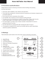
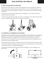
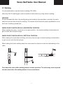
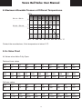
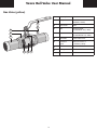
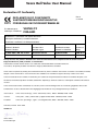
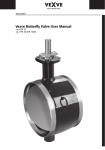
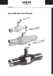
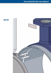
24.11.2008
Vexve Ball Valve User Manual
Vexve Ball Valve User Manual
Table of Contents
1.
General
2.
Precautions and Notifications
3.
Markings
4.
Valve Transportation and Storage
5.
Installations and Welding to the Pipeline
5.1 Welding
6.
Commissioning and Use
7.
Maintenance
7.1 Assembly/Disassembly of Ball Valve Manual Gear
7.1.1 The Adjusting/Assembly of the Manual Gear
7.2 Assembly/Disassembly of Manual and Electric Actuators (Auma)
7.3 Assembly/Disassembly of Pneumatic Actuators
8.
Maximum Allowable Pressure at Different Temperatures
9.
Kv Value Chart
10. Materials
Attachment: DECLARATION OF CONFORMITY
1. General
Vexve Steel Ball Valves (Colour blue)
Vexve fully welded ball valve is designed for clean mediums and to be used in e.g. district heating
pipelines, oil pipelines, and in general at pipeline applications where the water is oxygen-free.
Please consult with the manufacturer on other applicable applications.
The valve body is from pressure equipment steel. The shaft and ball are manufactured from the
stainless steel material. The ball seals are carbonized Teflon (PTFE). The stem sealing is done by
the O-rings. The O-rings are FPM (viton) rubber material. The valve is bi-directionally tight.
The valve opens when turning the manual gear to clockwise. The position indicator line at the
end of the stem shows the the ball’s position versus the stem. When the valve is open the handle
is aligned with pipeline. Also the indicator at the top of the stem is in line with the pipeline.
Vexve Oy is not responsible for the damages caused by unknown subjects or dirtiness. Vexve Oy
is also not responsible for the damages caused by improper handling or delivery.
2
Vexve Ball Valve User Manual
Vexve Stainless Steel Valve (Colour grey)
Vexve fully welded stainless steel ball valve is designed for clean mediums and to be used in
e.g. at the process applications. The valve is applicable e.g. most of the acids or different types
of waters, and e.g. certain calsium, sodium or potassium applications. Please consult with the
manufacturer on the suitability and also on the other applicable applications.
The valve body is from pressure equipment steel (stainless). The shaft and ball are manufactured
from the stainless steel material. The ball seals are carbonized Teflon (PTFE). The stem sealing
is done by the O-rings. The O-rings are FPM (viton) rubber material. The valve is bi-directionally
tight.
The valve opens when turning the manual gear to clockwise. The position indicator line at the
end of the stem shows the ball’s position versus the stem. When the valve is open the handle is
aligned with pipeline. Also the indicator at the top of the stem is in line with the pipeline.
Vexve Oy is not responsible for the damages caused by unknown subjects or dirtiness. Vexve Oy
is also not responsible for the damages caused by improper handling or delivery.
Vexve Gas Valve (Colour yellow)
Vexve fully welded shut-off gas ball valve is designed for natural gas transmission pipelines.
Please consult with the manufacturer, when the valve is used for other medium or applications.
The valve body is from pressure equipment steel. The shaft and ball are manufactured from the
stainless steel material. The ball seals are carbonized Teflon (PTFE). The stem sealing is done by
the O-rings. The O-rings are NBR rubber material. The valve is bi-directionally tight.

The valve opens when turning the manual gear to clockwise. The position indicator line at the
end of the stem shows the ball’s position versus the stem. When the valve is open the handle is
aligned with pipeline. Also the indicator at the top of the stem is in line with the pipeline.

Vexve Oy is not responsible for the damages caused by unknown subjects or dirtiness. Vexve Oy
is also not responsible for the damages caused by improper handling or delivery.
3
Vexve Ball Valve User Manual
2. Precautions and Notifications
Please read and notify the following instructions before handling and operating
the Vexve ball valves:

• Check the valve’s suitability to the medium and application.
• Check that the manufacturer’s informed maximum temperature and pressure ranges are not
exceeded (chapter 8)
• Do not heat the valve unnecessary from outside.
• The installed valve at pipeline can be extremely hot! Be protected!.
• The valve may not be used alone as a pipeline ending fitting. Always after the valve
a blank flange needs to be welded or/and connected to the pipeline end.
• The manual gear or actuator may not been removed or dismantled if the valve is
pressurized or/and it has flow.
• The valve should be un-pressurized when changing the stem O-ring(-s).
• If the pipeline is classified (I-III), check from the seller that the valve’s classification
meets the pipelines classification.
3. Markings
The identification plate locates at the valve body. It has the following information:
1
1. Valve DN size
2. Pressure class
3. Valve Body Material
4. Maximum Allowable Temperature
7. CE-Mark and the number
2
Material:
1,0345
3
T max:
200 ºC
Product no:
5. Valve type
6. Valve DN size
PN 40
DN 50
100050
4
5
6
7
8
9
11
of the notified body
8. Russian Valve Certification
9. Belarus Valve Certification
10.Manufacturer
11.Manufacturing Year
12.Manufacturer’s Internet Site
2006
www.vexve.fi
10
4
12
Vexve Ball Valve User Manual
4. Valve Transportation and Storage
Please check that the valve or its parts are not damaged during the transportation. Please also
check that the content of the delivery (valve types, sizes, etc.) is according to agreement. The
information on the possible damages or deviations in the content must be informed immediately
to Vexve Oy.
Store the valve at clean and dry storage before the installation. Do not remove the flow port
protectors before the installation.
Use lifting ropes when lifting the large size valves. It is forbidden to lift the valve from its actuator
or stem. If needed, please check the valve’s weight from Vexve Oy.
5. Installations and Welding to the Pipeline
The pipelines must be cleaned properly before installing the valves, otherwise the impurities may
damage the valve surfaces. During the cleaning/checking, check also that the is no dirtiness
at valve due the storage or transportation. Check that the valve’s maximum and minimum
temperatures are not exceeded! The maximum operational pressures and temperatures can be
found from the valve identification plate.
Do not remove the manual gear or actuator from the valve. If the manual gear or actuator needs
to be removed during the installation, please follow the actuator manufacturer’s instructions how
to adjust the actuator when reassembled (chapter 7).
To minimise the pressure shocks (in sizes DN 150/6” and bigger); it is recommended to use
bypass valve.
5
Vexve Ball Valve User Manual
5.1 Welding
It is recommended to use the electric welding (TIG, MIG).
Valve size DN 125 and bigger must be welded to the pipeline by using electric welding.
WELDING
Do not overheat the valve. Use cooling during the welding. Use wet fabric to protect the valve
seat from excess heat during the welding. The welder should have the proper qualification to do
this kind of welding procedures.

WHEN VALVE IS INSTALLED IN A HORIZONTAL POSITION:
When welding the valve, it must be in the open position - this avoids welding contamination to
get in touch with the ball surface.
WHEN VALVE IS INSTALLED IN A VERTICAL POSITION:
When making the upper seam welding, the valve must be open to avoid welding contamination
to get in touch with the ball surface.
When making the lower welding seam the valve must be closed to avoid the overheating of the
valve.
Cool down the valve (after welding) before normal operation. The valve may not be opened
or/and closed after the welding before it has cooled down.
6
Vexve Ball Valve User Manual
6. Commissioning and Use
The pipeline needs to be flushed carefully after the valve installation.
Commissioning Test Pressures
The largest allowable testing pressure is 1,1xPN, when the valve is closed.
During the pipeline pressure testing (1,5xPN), the valve needs to be open.
The shut-off valves are designed to be fully open or close. Check that the valve is either in open
or close position against the stopper (by turning the handle 90 degrees).
The valve may not be used alone as a pipeline ending fitting. Always after the valve a blank flange
needs to be welded or/and connected to the pipeline end.
When discharging the pipelines the valve has to be turned into a half-open position in order to
remove all liquid behind the ball. Important when the pipelines are discharged in temperatures
below 0 ºC.
7. Maintenance
The valves do not need extra service at the normal conditions, but to guarantee the good working
of the valves, opening and closing of the valve couple times in a year is highly recommended.
Change of O-rings
If needed, the upper O-ring(-s) of the stem can be replaced without draining the pipelines.
Follow the instructions, when changing the O-ring. Take care of all special circumstances and
when needed, contact the manufacturer. The instructions can be found from the Internet
www.vexve.fi or directly from the manufacturer.
7
Vexve Ball Valve User Manual
7.1 Assembly/Disassembly of Ball Valve Manual Gear
NOTE!
The manual gear or actuator may not been removed or dismantled if the valve is pressurized!

NOTE!
It is recommended to use the special actuator removal tools!

1. Turn the valve to the open position before the gear removal. The valve opens when turned
the gear handle to the counter-wise direction.
2. Turn the hand wheel slightly closed (to the point when the wheel turns easily)
3. Before the gear removal, remove the position indicator plate’s bolts (2), indicator plate (3)
and mark the shaft position to the actuator’s bush.(1).
4. Remove the actuator’s bolts and remove the actuator.
When assembling the manual gear, check that the stem bush adapter is in its original
position. There is no need to set the gear/actuator settings again when assembled to the
original position. If wanted to turn the gear/actuator 180 degrees, then the setting and fine-
tuning needs to be done according to the chapter
5. Install and tighten the bolts of the actuator/gear.
7.1.1 The Adjusting/Assembly of the Manual Gear
1. Turn the valve to the open position
2. Turn the gear to the open position. Clean the shaft (at the gear) and the bush. Crease the
manual gear’s bush (e.g. Spray Vaseline Würth HHS 2000)
3. Install the manual gear so that the hand wheel locates at the preferred position
4. Crease and install the nuts, screws and plates
5. Install the hand wheel to the manual gear
6. Turn the valve to open position.
7. Turn the valve to open position. The exact position will be checked from the valve shaft. The
ball needs to be centred to the seals. If you turn the valve too much open, then the 6. and 7
items need to be done once again.
8. Remove the caps from the stop screws (4).
9. Open and loose the locking screws.
10.Tighten the open position stop screw (7) and lock the screw with the locking screw (5).
11.Turn the ball 90 degrees closed.
12.Tighten the stop position screw (6) and lock the screw with locking screw (5).
8
Vexve Ball Valve User Manual
2
3
1
7
6
5
4
9
Vexve Ball Valve User Manual
7.2 Assembly/Disassembly of Manual and Electric Actuators (Auma)
NOTE
The manual gear or actuator may not been removed or dismantled if the valve is
pressurized!
It is recommended to use the special actuator removal tools!
1. Turn the valve to the open position before the actuator removal by turning the manual
gear’s wheels.
2. Turn the power off (for the actuator)
3. Turn the handle a bit close so that that the valve wheel/spindle turns easily.
4. Before the gear removal, mark the position and place of the bushing (1) against
to the valve and the actuator.
5. Remove the actuator’s bolts and remove the actuator. The bushing (1) will stay at the stem.
6. When assembling the manual gear, check that the stem bush adapter is in its original
position. There is no need to set the gear/actuator settings again when assembled to the
original position. If wanted to turn the gear/actuator 180 degrees, then the setting and fine-
tuning needs to be done according to the chapter “manual gear adjusting”.
7. Install the actuator, and tighten the bolts of the actuator/gear.
Ball Valve Actuator Adjusting (Manual Gear and Electric Actuator (AUMA))
1. Turn the valve to open position
2. Place the bushing to the right level/height. The height needs to be measured from the gear.
Tighten the locking screw (6) with the hexagon key.
3. Turn the gear/actuator to open position, and install the manual gear so that the hand wheel
comes to the preferred direction.
4. Crease, install and tighten the manual gears/actuators bolts.
5. Install the hand wheel to the gear/actuator.
6. Turn the hand wheel couple of turns to open the valves. Remove the limiting bush’s (8)
fastening screws (7) so the bush can turn freely.
7. Turn the valve to the open position. The exact position will be checked from the valve shaft.
The ball needs to be centred to the seals. If you turn the valve too much open,
then the 6. and 7 items need to be done once again.
8. After finding the right open position has been found, turn the limiting bush slightly to
clockwise direction to position where it does not move anymore. Then turn back the bush
app. 1/8 turn. Pull the bush out of its bores (app. 2cm) and install the limiting bush back to its
place so that the holes of the bush are in the line with the gear’s holes.
10
Vexve Ball Valve User Manual
8. After finding the right open position has been found, turn the limiting bush slightly to
clockwise direction to position where it does not move anymore. Then turn back the bush
app. 1/8 turn. Pull the bush out of its bores (app. 2cm) and install the limiting bush back to its
place so that the holes of the bush are in the line with the gear’s holes. AUMA GS 160 and
larger gears the limiting bush does not need to pull out of its bores. In larger valves, the bush
will be tightened directly to the right position with the flanges.
9. Turn the valve closed. Check that the closed positioner/limit is at right position.
10.Turn the power on to the electric actuator and install the limit switches and moment switches
according to the AUMA’s instructions.
2
3
4
5
8
7
6
1
7.3 Assembly/Disassembly of Pneumatic Actuators
NOTE!
The manual gear or actuator may not been removed or dismantled if the valve is pressurized.
It is recommended to use a special tools and equipment (designed for actuator removal) when
disassembling the valve.
Assembly and disassembly will be done according to the actuator manufacturer’s instructions;
and also at the same time following/notifying the maximum torque values.
11
Vexve Ball Valve User Manual
8. Maximum Allowable Pressure at Different Temperatures
MPa
DN 10 – DN 50
PN 40
4
3
DN 65 – DN 600
PN 25
2
1
-30
0 +30 60 90 120 150 180 210 °C
Contact the manufacturer, if the temperature is below 0 ºC.
9. Kv Value Chart
Kv Values when Valve Fully Open:
Reduced bore valves
DN
10
15
20
25
32
40
50
65
80
KV
8
8
14
25
41
65
103
180
290
DN
100
125
150
200
250
300
350
400
500
600
KV
470
830
1150
1750
3200
4600
6600
13300
18700
29800
Full bore valves
DN
15
20
25
32
40
50
65
80
100
KV
14
25
41
65
103
180
290
470
830
DN
125
150
200
250
300
350
400
500
600
KV
1150
1750
3200
4600
9600
13300
18700
30000
65000
12
Vexve Ball Valve User Manual
10. Materials
Steel Valves (blue)
7.
9.
2.
8.
1.
6.
5. 3. 4.
No
Description
Material
1.
Body
Steel, EN 10217-2
P235GH (1.0345)
2.
Stem bush
Steel
3.
Ball
Stainless Steel,
EN X5CrNi18-10 (1.4301)
4.
Stem
Stainless Steel,
EN X5CrNiS18-9 (1.4305)
5.
Ball Seals
Carbonized PTFE
6.
Extension
pipes
Steel, EN 10217-2
P 235GH (1.0345)
7.
Handle
Galvanized Steel
8.
O-ring
FPM
9.
Bush
PTFE
No
Description
Material
1.
Body
Stainless Steel,
EN 10217-7
X2CrNiMo17-12-2 (1.4404)
2.
Stem bush
Stainless Steel,
EN X2CrNiMo17-12-2
3.
Ball
Stainless Steel,
EN X2CrNiMo17-12-2
4.
Stem
Stainless Steel,
EN X2CrNiMo17-12-2
5.
Ball Seals
Carbonized PTFE
6.
Extension
pipes
Stainless Steel,
EN 10217-7
X2CrNiMo17-12-2 (1.4404)
7.
Handle
Stainless Steel
8.
O-ring
FPM
9.
Bush
PTFE
Stainless Steel Valve (grey)
7.
9.
8.
2.
1.
6.
5. 3. 4.
13
Vexve Ball Valve User Manual
Gas Valve (yellow)
7.
9.
2.
8.
1.
6.
5. 3. 4.
14
No
Description
Material
1.
Body
Steel, EN 10217-2
P235GH (1.0345)
2.
Stem bush
Steel
3.
Ball
Stainless Steel,
EN X5CrNi18-10 (1.4301)
4.
Stem
Stainless Steel,
EN X5CrNiS18-9 (1.4305)
5.
Ball Seals
Carbonized PTFE
6.
Extension
pipes
Steel, EN 10217-2
P 235GH (1.0345)
7.
Handle
Galvanized Steel
8.
O-ring
NBR
9.
Bush
PTFE
Vexve Ball Valve User Manual
Declaration Of Conformity
0575
DECLARATION OF CONFORMITY
VAATIMUSTENMUKAISUUSVAKUUTUS
FÖRSÄKRAN OM ÖVERENSSTÄMMELSE
The Manufacturer:
Valmistaja / Tillverkare:
Rev.5
2.1.2008
VEXVE OY
FINLAND
Manufacturer´s certificates and applied directives:
Valmistajan sertifikaatit ja sovelletut direktiivit:
Tillverkarens certifikater och tillämpade direktiv:
Standard / Directive
Notified Body
Certificate no.
Valid
Standardi / Direktiivi
Ilmoitettu laitos
Sertifikaatin numero
Voimassa
Standard / Direktiv
Anmälda organ
Nummer av Certifikat
Giltig
ISO 9001:2000 + EN 729-2:1994
Det Norske Veritas
96-HEL-AQ-208
2009-08-31
PED 97/23/EC Module H
Det Norske Veritas 0575
PED-H-112
2010-10-08
Hereby declares that products detailed below have been manufactured in compliance with the above Pressure
Equipment Directive ( PED ) 97/23/EC, as stated below.
Vakuutamme että alla mainitut tuotteet ovat valmistettu Painelaitedirektiivin 97/23/EY mukaisesti.
Vi försäkrar, att följande produkter har tillverkats enligt Tryckkärlsdirektivet 97/23/EG.
Vexve valves completed by welding are manufactured either by steel or stainless steel. Valves connections are welded, threaded,
flanged or these combinations. Trace documents are available from manufacturer against the body number of the valve.
Vexven hitsaamalla kootut venttiilit on valmistettu, joko teräksestä tai haponkestävästä teräksestä. Venttiilien liitospäät, ovat
hitsattavia, kierteellisiä, laipallisia tai näiden yhdistelmiä. Jäljitettävyys tallenteet saatavissa valmistajalta venttiilin runkonumeroa
vastaan.
Vexve helsvetsade ventiler är tillverkade av stål eller syrafast stål. Anslutningsformer är svetsändar, gängändar, flänsar eller
kombinationer av dessa. Dokumenten finns tillgängliga från tillverkaren mot spårningsnummret på ventilhuset.
The Products:
Vexve ball-, balancing-, control- and butterfly valves, DN32 - DN1000, PN16 - PN40
Tuotteet:
Vexve pallo-, säätö-, jatkuvasäätö- ja läppäventtiilit, DN32 - DN1000, PN16 – PN40
Produkter:
Vexve kul-, injusterings-, regler- och vridspjällventiler, DN32 – DN1000, PN16 – PN40
Vammala, Finland 02.01.2008
VEXVE OY
Janne Vinha
Product Manager
15
Vexve Oy • Pajakatu 11 • 38200 Vammala
Puh. 010 734 0800 • Fax 010 734 0839 • [email protected] • www.vexve.fi