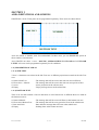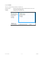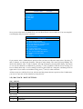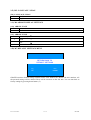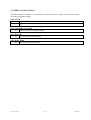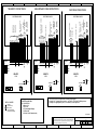
1
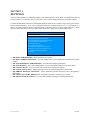
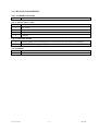
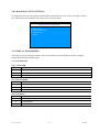
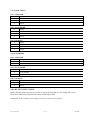
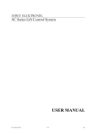
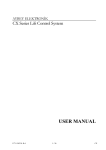
AYBEY ELEKTRONİK GRAFIX Lift Display System USER MANUAL F/7.5.5.02.77 R:0 1 / 12 GRAFIX GRAFIX LIFT DISPLAY SYSTEM USER MANUAL VERSION: 1.00 AYBEY ELEKTRONİK LTD. STI. Factory : Orhanli Mah. Katip Celebi Cad. No:17 Tuzla-Istanbul / Turkey Tel: (90) (216) 394 50 55-56-57 Fax: (90) (216) 394 50 58 Office : Kartal Cad. No:39 Yakacik-Kartal-Istanbul Tel : (90) (0216) 377 08 02 – 309 06 45 Fax : (90) (216) 451 58 68 e-mail: [email protected] www.aybey.com F/7.5.5.02.77 R:0 2 / 12 GRAFIX PREFACE PREFACE.............................................................................................................................................................. 3 SECTION 1 ............................................................................................................................................................ 4 AREA DEFINITIONS AND SCREENS ............................................................................................................. 4 1-A) PROPERTIES OF AREAS..................................................................................................................... 4 1-A-1) SIDE TEXT ...................................................................................................................................... 4 1-A-2) BOTTOM TEXT ............................................................................................................................. 4 1-A-3) NUMBER ......................................................................................................................................... 5 SECTION 2 ............................................................................................................................................................ 6 SETTINGS ............................................................................................................................................................. 6 2-A) M0-MAIN PARAMETERS .................................................................................................................... 7 2-B) M1-DISPLAY TEXT SETTINGS .......................................................................................................... 8 2-C) DISPLAY PARAMETERS ..................................................................................................................... 8 2-C-1) SUBTITLES ..................................................................................................................................... 8 2-C-2) SIDE TEXTS.................................................................................................................................... 9 2-C-3) NUMBERS ....................................................................................................................................... 9 2-D) M3-TEXT INPUT MENU....................................................................................................................... 9 2-E) M4-CLOCK / DATE SETTINGS......................................................................................................... 10 2-F) M5- LANGUAGE / LİSAN ................................................................................................................... 11 2-G) M6-ARROW DISPLAY SETTINGS ................................................................................................... 11 2-H) M7-DEFAULT SETTINGS MENU ..................................................................................................... 11 2-I) SIMULATOR SETTINGS ..................................................................................................................... 12 F/7.5.5.02.77 R:0 3 / 12 GRAFIX SECTION 1 AREA DEFINITIONS AND SCREENS GRAFIX has 3 areas. These parts can be programmed separately. These areas are shown below. SIDE TEXT NUMBER BOTTOM TEXT Areas are named as Number, Side Text and Subtitle. In these areas, you can PROGRAM system to show number, text and arrow. Also GRAFIX can show 3 cases : MOVING, APPROACHING TO FLOOR and AT FLOOR LEVEL. All areas can be programmed separately for all conditions. 1-A) PROPERTIES OF AREAS 1-A-1) SIDE TEXT 7 lines * 9 characters are written in the side Text area. 4 different projections are made in the side Text area: a) General Side Text b) Floors Own Sidetext c) Arrow d) Empty : The message that will be seen in the side text area at all floors. : The message that will be seen in the side text area special to floor. : Arrow projection in the side text area. : Empty message shown at the related line 1-A-2) BOTTOM TEXT There is an area that contains 1 line 24 characters to write bottom text. 4 different shows are made at the bottom text area : a) General Subtitle b) Floors Own Bottom Text c) Date and Clock d) Empty F/7.5.5.02.77 R:0 : The message that will be seen at all floors in the bottom text area. : The message that will be seen (special to floors in the subtitle area. : Date and time message that will seem at the subtitle area : Nothing show at the bottom text area. 4 / 12 GRAFIX 1-A-3) NUMBER There are 3 different display alternative at number area. a) Floor Number b) Arrow c) Empty : Shows the floor number. Single or double characters can be used. : Arrow show at the number area. : Nothing show at the number area. Side Text Area a) Global Side Text b) Floor Text c) Arrow d) Empty Number Area a) Floor Number b) Arrow c) Empty Subtitle Area a) Global Subtitle F/7.5.5.02.77 R:0 b) Subtitle special to floor 5 / 12 c) Time GRAFIX SECTION 2 SETTINGS There are three buttons on GRAFIX module. The buttons that are in the back of GRAFIX are named as ENT (Enter), (↓) (increase) and (↑) (decrease). You can do settings mostly by using this buttons. To enter the GRAFIX menu press ENT button until the menu occurs on the screen. Firstly you will see the sub-menu alternative. You can see GRAFIX menu by clicking direction ((↑) ve (↓)) buttons. To choose an item, click ENT button when the cursor is on that item. If you press ENT button for a short time you enter that menu, but if you press ENT button for a short time you leave that menu. MAIN MENU M0 M1 M2 M3 M4 M5 M6 M7 M8 << MAIN PARAMETERS MAIN SCREEN SETTINGS FLOOR DISPLAY PARAMETERS FLOOR TEXT SETTINGS CLOCK/DATE LANGUAGE/LİSAN ARROW DISPLAY SETTINGS SET TO FACTORY DEFAULTS SIMULATOR SETTINGS EXIT • M0-MAIN PARAMETERS : Main parameters of system. • M1-MAIN SCREEN SETTINGS : You can change texts, service mode and overload texts by this button. • M2-FLOOR DISPLAY PARAMETERS : Text and clock display parameters • M3-FLOOR TEXT : Floor texts and numbers are set by this button and preview can be done. • M4-CLOCK / DATE : You can set the time and set show font by this button. • M5-LANGUAGE / LiSAN : Menu language can be set (Turkish/English) by this button. • M6-ARROW DISPLAY SETTINGS : Arrow animation position and style can be designed by this button. • M7-SET TO FACTORY DEFAULTS : It returns to the fabric settings if you accept. • M8-SIMULATOR SETTINGS: You can reach simulator settings by clicking this button. F/7.5.5.02.77 R:0 6 / 12 GRAFIX 2-A) M0-MAIN PARAMETERS [A0] NUMBER OF FLOORS 1…64 Number of floors in system [A1] CONNECTION TYPE 0 Binary 1 Gray Code 2 7 Segment 3 Counter 4 CAN-Bus [A2] ECONOMY MODE 0 Economy Mode (Turn off backlight if it does not sense any movement for 10 minutes) 1 Normal Mode (No energy saving) [A3] BUZZER 0 Disabled 1 Enabled F/7.5.5.02.77 R:0 7 / 12 GRAFIX 2-B) M1-DISPLAY TEXT SETTINGS By using this menu you can organise Global subtitle, global side text, out of service text and overload text. Global text is not related to floor, they can be seen at all floors. DISPLAY TEXT SETTINGS B0 B1 B3 B4 << SUBTITLE SIDE TEXT OUT OF SERVICE OVERLOAD BACK 2-C) DISPLAY PARAMETERS This menu is used for setting of subtitle, side text and number areas at the floor position, coming to floor position and movement position. 2-C-1) SUBTITLES [C0] AT FLOOR 0 Empty 1 Floor Subtitle 2 Global Subtitle 3 Date / Time [C1] SLOW MODE 0 Empty 1 Floor Subtitle 2 Global Subtitle 3 Date / Time [C2] ON MOVE 0 Empty 1 Floor Subtitle 2 Global Subtitle 3 Date / Time F/7.5.5.02.77 R:0 8 / 12 GRAFIX 2-C-2) SIDE TEXTS [C3] AT FLOOR 0 Empty 1 Floor Side Text 2 Global Side Text 3 Arrow [C4] SLOW MODE 0 Empty 1 Floor Side Text 2 Global Side Text 3 Arrow [C5] ON MOVE 0 Empty 1 Floor Side Text 2 Global Side Text 3 Arrow 2-C-3) NUMBERS [C6] AT FLOOR 0 Empty 1 Floor Number 2 Arrow [C7] SLOW MODE 0 Empty 1 Floor Number 2 Arrow [C8] ON MOVE 0 Empty 1 Floor Number 2 Arrow 2-D) M3-TEXT INPUT MENU Before entering menu of text input, you have to choose the floor that you will change and set text. Enter Floor number by using direction buttons and then press ENT. WARNING: If floor number has one digit, you have to choose the first digit 0. F/7.5.5.02.77 R:0 9 / 12 GRAFIX ENTER TEXT 8.FLOOR D0 SUBTITLE D1 NUMBER D2 SIDE TEXT D3 PREVIEW << BACK Now you are at the menu of related floor, you can choose floors own text and icon. You can setup full screen display and you can see a preview. MAIN MENU M0 MAIN PARAMETERS M1 MAIN SCREEN SETTINGS M2 FLOOR DISPLAY PARAMETERS M3 FLOOR TEXT SETTINGS M4 CLOCK/DATE M5 LANGUAGE/LİSAN M6 ARROW DISPLAY SETTINGS M7 SET TO FACTORY DEFAULTS M8 SIMULATOR SETTINGS << EXIT Which Floor?: 0_ If you want to write a subtitle that is special to floor you have to follow the steps below. By using (↑) and (↓) buttons, we choose the character. Then press enter shortly. The cursor will stop blinking. We choose the character with (↑) and (↓) buttons. Save the character by pressing ENT shortly. Now again we can see the characters of underline by pressing (↑) and (↓) buttons. Until the end of writing, you have to follow these steps. To save settings you have to press ENT for a long time, and than go back to upper menu. If you want to exit without saving, press (↑) and (↓) at the same time. All these steps are valid for floor icon, side text and the pictures that are special to floor. Furthermore, you can see a preview of floor number by using Preview. 2-E) M4-CLOCK / DATE SETTINGS [E0] ADJUST S0 Hour S1 Minute S2 Day S3 Month S4 Year [E1] FONT 0 Monospac821 1 BankGothic F/7.5.5.02.77 R:0 10 / 12 GRAFIX 2-F) M5- LANGUAGE / LİSAN [F0] LANGUAGE / LİSAN 0 Turkish 1 English 2-G) M6-ARROW DISPLAY SETTINGS [G0] ARROW STATE 0 Animated 1 Static [G1] ARROW STYLE 0 Classical Style 1 2 3 Star Classical Arrow Hand 2-H) M7-DEFAULT SETTINGS MENU ARE YOU SURE RETURN BACK TO DEFAULT SETTINGS NO YES UP DOWN GRAFIX returns to default settings with this menu. Floor numbers are shown with 0-63 numbers. All the personal settings will be deleted. There will be an arrow on the side title. You can turn back to factory settings by pressing down button (↓). F/7.5.5.02.77 R:0 11 / 12 GRAFIX 2-I) SIMULATOR SETTINGS GRAFIX includes a simulator to see the settings without connecting a board. The parameters below are used for simulator settings. [H0] STATE 0 Off 1 On [H1] NUMBER OF FLOORS 1…64 Number of floors in simulator mode. [H2] MOTION 1…99 Active time of movement signal [H3] WAIT TIME 1…99 Active time of waiting at floor. F/7.5.5.02.77 R:0 12 / 12 GRAFIX GRAY/BINARY CODE CONNECTIONS BOARD SUPPLY D 100 1000 (12V DC) EMERGENCY LAMP 0V +12V SIGNAL LAMP OUTPUTS SAYICI VE LİMİT ŞALTER ÇIKIŞLARI BOARD SUPPLY 100 1000 0V +12V 12 31 32 39 35 SIGNAL LAMP OUTPUTS (12V DC) EMERGENCY LAMP CONTROL PANEL M0 817 818 G0 / B0 G1 / B1 G2 / B2 G3 / B3 G4 / B4 G5 / B5 FAST MOTION INPUT GRAY/BINARY CODE OUTPUTS BOARD SUPPLY + - (12V DC) EMERGENCY LAMP 0V +12V SIGNAL LAMP OUTPUTS A B C D E F G 2G (-) 2BC (1) 2A (2) 12 31 32 39 35 DIGITAL DISPLAY OUTPUTS CONTROL PANEL 12 31 32 39 35 CONTROL PANEL D COUNTER CONNECTIONS FAST MOTION INPUT 7 SEGMENT CONNECTIONS COM3 COM3 SIGNAL LAMPS 12 (Busy) 31 (Down Arrow) 32 (Up Arrow) 35 (Over Load Lamp) 39 (Out of Service Lamp) + Set coding type related connection inputs M0- MAIN PARAMETERS A1- CONNECTION 0- Binary Code 1- Gray Code 2- 7 Segment (Digital Display) 3- Counter (M0) 4- Can Bus (Serial Communication) COM3 V+ GND CL CH I1 I2 I3 I4 12 31 32 35 39 M0 817 818 V+ GND CL CH GRAFIX LCD LCD BUZZER BUZZER CONTRAST CONTRAST - COM2 GRAFIX BUZZER ENT COM1 COM3 LCD B +COM1 COM2 COM3 GRAFIX A COM2 12V DC COM1 12V DC M0 M1 M2 M3 M4 M5 I1 I2 I3 I4 12 31 32 35 39 V+ GND CL CH A B C D E F G 12V DC COM1 COM2 - COM3 COMMONS + COM2 +- - COM1 COMMONS + COM1 COM2 - +- + COMMONS (-) C 1X 2X 12 31 32 35 39 C ENT - + B CONTRAST - ENT + Set COM1, COM2, COM3 dip-switches according to input signals. Example-1 : If 7 segment inputs are minus (-) set to plus (+) COM1 and COM2 dip-switches. Example-2 : If signal inputs are plus (+) set to minus (-) COM-3 dip-switch. A F/ 7.05.05.02.19 This document is a sample for applications. All information contained in these materials are subject to change by Aybey Elektronik without notice. Aybey Elektronik assumes no responsibility for any damage, liability, or other loss rising from these inaccuracies or errors. GRAFIX GLCD CONNECTION DIAGRAM AYBEY ELEKTRONİK SERIES GRAFIX DRW. M. AKKUŞ PROJ. GLCD001 APPRV. M. AYBEY REV. DATE 00 12 JAN 12