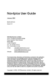
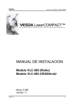
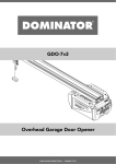
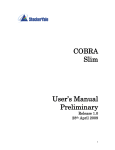
1
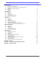
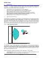
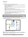
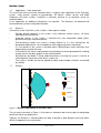
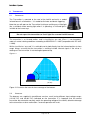
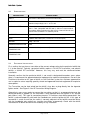
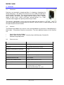
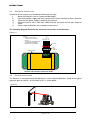
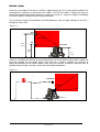
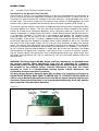
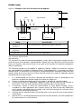
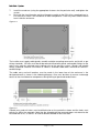
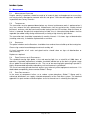
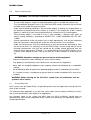
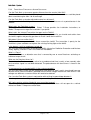
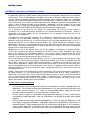
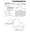
Fork-Alert System
User Manual
Fork-Alert™ System
Copyright Global 7 Group Pty Ltd 2006-2014. All rights reserved.
Reproduction, transfer, distribution or storage of part or all of the contents in this document in any form without the prior written consent of Global 7 Group Pty Ltd is
prohibited.
Fork-AlertTM is a registered trademark of Imatek Group Pty Ltd. Global 7 Group Pty Ltd is the exclusive worldwide manufacturer of Fork Alert™ systems.
Global 7 Group Pty Ltd operates a policy of continuous development. Global 7 Group Pty Ltd reserves the right to make changes and improvements to any of the
products described in this document without prior notice.
Global 7 Group Pty Ltd assumes no responsibility for any errors that may appear in this document, nor does it make expressed or implied warranty of any kind with
regard to this material, including, but not limited to, the implied warranties of merchantability and fitness for a particular purpose.
Global 7 Group Pty Ltd shall not be liable for incidental or consequential damages in connection with, or arising out of the furnishing, performance, or use of this
document and the material it describes.
The availability of particular accessories may vary by region.
Fork-Alert™ System
1. INTRODUCTION
1.1
1.2
1.3
1.5
1.6
1.7
BASIC OPERATING PRINCIPLE
APPLICATION - AUTOMATED PEDESTRIAN W ARNING SYSTEM
BENEFITS
APPLICATIONS – DOOR AUTOMATION
BENEFITS
EXAMPLE
2. TRANSMITTER
2.1
2.2
2.3
2.4
2.5
OPERATION
VERSIONS
SPECIFICATIONS
ELECTRICAL INSTALLATION
PHYSICAL INSTALLATION
3. RECEIVER
3.1
3.2
3.3
3.4
3.5
3.6
3.7
OPERATION
VERSION
SPECIFICATIONS
ELECTRICAL INSTALLATION
PHYSICAL INSTALLATION
INTERNAL TIMER FUNCTION AND ADJUSTMENT
INTERNAL RECEIVER DETECTION RANGE ADJUSTMENT
4. ZONE CONTROLLER
4.1
4.2
4.3
4.4
4.5
OPERATION
VERSIONS
SPECIFICATIONS
ELECTRICAL INSTALLATION
PHYSICAL INSTALLATION
5 MAINTENANCE
5.1
5.2
5.3
5.4
5.5
5.6
5.7
5.8
5.9
5.10
MAINTENANCE OVERVIEW
TRANSMITTER
RECEIVERS
ZONE CONTROLLER & PERIPHERALS
PART REPLACEMENT
TROUBLESHOOTING
OPERATIONAL AND MAINTENANCE PRECAUTIONS
SAFETY PRECAUTIONS
SYSTEM SIGN-OFF
FORK-ALERT FREQUENTLY ASKED QUESTIONS
1
1
1
2
3
3
3
4
4
4
5
5
6
7
7
7
7
8
8
10
11
13
13
13
13
14
16
18
18
18
18
18
18
19
20
22
22
23
APPENDIX 1 -SPARES
24
APPENDIX 2- LIMITATIONS AND CONDITIONS OF SALE
25
APPENDIX 3 – SIGN OFF SHEET
26
Fork-Alert™ System
1.
INTRODUCTION
Fork-Alert is a Vehicle Proximity Detection System that utilises patented SweepscanTM
technology. Its unique combination of the following features provides many benefits in
comparison with alternative vehicle sensor technologies:
•
•
•
•
•
•
•
Wide 10metre/32’10” radius detection zone (early triggering)
360° omni directional triggering (detection from any angle/orientation)
Specific triggering range (accurate and consistent detection zone)
Definable detection zone (controlling triggering to the immediate environment)
Does not make use of Radio Frequency technology (not subject to interference)
Indoor and outdoor functionality (suitable to most environments)
Modular design for easy installation (low cost, low impact)
1.1
BASIC OPERATING PRINCIPLE
The principle of the SweepscanTM technology is the remote detection of a coded infrared signal
from a transmitter attached to a forklift or other vehicle. The signal sensor, called a Receiver, has
an accurately adjustable range and a wide detection zone which is easily configured for specific
applications. The Transmitter, which is designed for most types of forklifts or other vehicle,
transmits the invisible signal 360° around the forklift or other vehicle ensuring that the forklift or
other vehicle will be detected regardless of its orientation or direction relative to any Receiver.
Figure 1.1 Basic Operating Principle
Rotating IR Signal
Detection Zone
TRANSMITTER
(Beacon)
RECEIVER
(sensor)
1.2
APPLICATION - AUTOMATED PEDESTRIAN W ARNING SYSTEM
The Fork-Alert system’s major application is to warn pedestrians of the presence of forklifts or
other vehicle. It can be used to supplement existing safety measures by providing an additional
automatic warning for pedestrians when a piece of mobile plant (i.e., forklift) is within a specified
location. For example, where a machine might be approaching a doorway or blind corner and is
obscured from the pedestrian’s view.
Global 7 Group offers additional components for this application. These include:
•
•
A Zone Controller to power the Receivers and switch mains power to wiring devices, and
Warning Devices such as warning lights and audible alarms.
Page 1 of 28
Fork-Alert™ System
1.3
BENEFITS
Benefits of the Fork-Alert system for warning pedestrians include:
•
Improves Occupational Health and Safety through earlier and more visible notification to
pedestrians of approaching vehicles.
•
Supplements normal driver warnings with automatic early warning systems around blind
corners, through doorways, etc.
•
Visible warning systems overcome the problems associated with noisy factories or busy
warehouses.
•
Reduces the risk of pedestrian death or injury.
•
Reduces the likelihood of operations being disrupted by an accident.
•
Predictable range and coverage that can extend as far as necessary through a chained receiver
system.
•
Line of sight characteristics of infrared, allowing system to adapt to specific site layout.
•
Range remains unaffected by nearby metal plant or equipment (unlike radio frequency
systems) provided the infrared beams have line of sight.
•
Straightforward and quick to install (by any authorized electrical contractor).
•
Modular for future expansion.
Note: Global 7 Group Pty Ltd supplies the Fork-Alert system on the sole basis that the
user fully understands it is intended to supplement, rather than replace, industry safety
procedures and regulations applying to the use of forklifts or other mobile plant.
1.4
EXAMPLE (Refer to Figure 1.2 Example Application to warn pedestrians)
The following site layout schematic details the locations of the components needed to install the
Fork-Alert system at a blind corner.
Figure 1.2 Example Application to warn pedestrians
Typically, the receivers are mounted on one side of a doorway or blind spot to detect an
approaching forklift or other vehicle. Warning devices are placed in strategic positions to
effectively warn pedestrians of the approaching hazard.
Page 2 of 28
Fork-Alert™ System
1.5
Applications – Door Automation
The use of Fork-Alert to activate automatic doors is another major application of the Fork-Alert
system. With features superior to ground-loops, PE Beams, motion sensors and Radio
Frequency (RF) base systems, Fork-Alert is extremely effective as an activation sensor for
automatic doors.
In this application no additional components are required.
interfaced directly to the existing door controller.
1.6
The Receivers are powered and
BENEFITS
The benefits of the Fork-Alert system used as a Door opener include:•
Provides greater efficiency as the system is fully automatic (always active); no action
required by the forklift driver
•
Improved security as the system is activated only from designated mobile plants,
preventing entry by unwanted vehicles.
•
Environmentally friendly, the system is energy efficient as it is only activated by the
designated mobile plants, not susceptible to false triggering by other movements.
•
It is site specific as the system is activated within a defined zone, which eliminates false
triggering from outside the zone.
•
A 10 metre/32’10” radius range provides early detection of the designated forklift, allowing
enough time for the door to open for the entering forklift.
•
Activated only by Global 7 Group coded transmitters ensuring the system is immune to
radio frequency interference from drives, motors etc.
•
The system is flexible and can be applied to indoor and/or outdoor situations un-affected
by sunlight.
1.7
EXAMPLE
LEGEND
IR RECEIVER RANGE
INFRARED RECEIVER
FORKLIFT
AUTOMATIC
DOOR
TRANSMITTER
PEDESTRIAN
WALKWAY
PEDESTRIAN
Figure 1.3 Example Application to activate a door
The site layout schematic in Figure 1.3 illustrates an automatic door that will open for designated
forklifts but not for any pedestrians.
Typically, the Receiver is mounted above the door to provide a wide detection zone that allows
forklifts to approach from any direction.
Page 3 of 28
Fork-Alert™ System
2.
2.1
TRANSMITTER
OPERATION
The Transmitter is mounted to the roof of the forklift and emits a coded
infrared beam in all directions. It is coded to eliminate accidental triggering.
Note that you will not see the Transmitter flashing or emitting any visible light
like a standard visible warning light when it is operating, as infrared light is
invisible to the human eye.
Do not expect the transmitter to ‘flash’ light like a normal forklift beacon.
The transmitter is an infrared emitter, and is classified as eye safe (Class 1- non-hazardous)
under all normal viewing conditions according to AS/NZS 2211.1:1997 (compatible with IEC 8251:1993).
Whilst classified as “eye safe” it is advisable not to look directly into the Infrared emitter at close
range. Always assume that the transmitter is emitting invisible infrared signals if the mirror is
rotating or if the transmitter is not rotating but powered up.
Figure 2.1
60°
Up to 10 metres
(32’10”)
Figure 2.1 illustrates the transmission coverage of the beacon.
2.2
VERSIONS
The beacons are supplied in two different versions, each having different input voltage ranges
(12-24V DC, and 36-48V DC) indicated on the transmitter. It is important that the correct
transmitter be selected to correctly match the operating voltage of the forklift, otherwise damage
to the transmitter or other malfunction / incorrect operation will result.
Page 4 of 28
Fork-Alert™ System
2.3
SPECIFICATIONS
DESCRIPTION
SPECIFICATION
INPUT
DC12/24V or DC36/48V (check transmitter label)
OUTPUT
Infrared Emission Peak Wavelength, λ=870nm
Nominal Output Angle, θtx = -15º to +45º
OPTICAL SAFETY
Class 1 (Non-hazardous) infrared emitter according to AS/NZS
2211.1:1997 (compatible with IEC 825.1). Observe recommended
precautions during maintenance with covers removed. Do not stare
into the infrared emitters or stationary mirror.
CURRENT
Approximately 0.25A
SIZE
130Wx175Hx130D (mm) / 5’4”W x 6’11”H x5’4”D (inch)
WEIGHT
500g / 1lbs 2oz
INGRESS PROTECTION
IP66
OPERATING
TEMPERATURE
0° to 45° Celsius (32° to 113° F)
STORAGE
TEMPERATURE
0° to 45° Celsius (32° to 113° F)
2.4
ELECTRICAL INSTALLATION
First, confirm that you have a transmitter of the correct voltage rating for the particular forklift that
it is to be fitted to. Typically, gas/petrol forklifts require a 12-24V DC transmitter, and electric
forklifts a 36-48V DC transmitter. However, this may vary and must be confirmed before
installation.
Secondly, confirm that the particular forklift is not used in designated hazardous areas where
there is a requirement for approved electrical equipment for explosive atmospheres. Do not fit the
Fork-Alert transmitter to this type of forklift, as the Fork-Alert system has not been approved for
use in explosive areas requiring specially tested and approved electrical equipment for explosive
atmospheres.
The Transmitter can be hard wired into the forklift’s fuse box, or plug directly into the cigarette
lighter socket. See Figure 2.2 for IR Transmitter Wiring Diagram.
Alternatively, many users prefer to connect the transmitter so that it is un-powered whenever the
forklift park brake is applied (i.e. the transmitter is only powered when the ignition is on, and the
park brake is off). This type of connection prevents a Fork-Alert alarm being generated if the
forklift is parked temporarily with both the handbrake on and the ignition left on. If this type of
connection is used, ensure that the switch is correctly adjusted so the forklift cannot be driven
with the handbrake only partially on (and the transmitter un-powered). Check with the forklift
manufacturer or dealer to confirm the suitability of any installation.
Page 5 of 28
Fork-Alert™ System
WARNING: If the transmitter is wired with reverse polarity the rotating
mechanism will still spin, but the red status light will not be on. Do not operate
the transmitter if wired incorrectly – ensure that the red status light is on
Figure 2.2
2.5
PHYSICAL INSTALLATION
The transmitter must be mounted on the roof of the forklift with no objects blocking the line-ofsight to the receiver. This may require an extension pole for the transmitter. The transmitter is
available with magnetic base mount, pole mount or screw mount. Transmitter shape and profile
may vary between models.
Figure 2.3 Beacon Mounting (Screw Mount)
120°
7mm
130mm
5Nm
( 5”1”)
The belt drive that rotates the transmitter mirror must be set according to the supply voltage as
per the following diagram. Always turn the transmitter off before changing the belt or belt settings.
Figure 2.4
24 V DC
12, 36, 48 V DC
Page 6 of 28
Fork-Alert™ System
3.
RECEIVER
3.1
OPERATION
Receivers are mounted in strategic positions (i.e. doorways) throughout the
factory/warehouse, and detect the presence of the coded Infrared beam
from the forklift Transmitter. They are connected to either a Zone Controller,
which converts the forklift-sense trigger from the receiver into a suitable
output to drive sirens, alarms and other warning devices, or a Door
Controller which triggers the opening and closing of a door.
The receiver is designed in such a way that the output from the receiver is ‘fail-safe’. That is, in
the event of power being removed from the receiver, receiver failure or cable damage, the unit
will report the presence of a forklift.
3.2
VERSION
The Receiver described in this manual is the current production version which is identifiable by its
black colour. (The previous Receivers were white.) The main additional features of this Receiver
are:
•
•
•
Internal timer for the ‘off-delay’
Relay Output selection switch - Normally Open (NO)/Normally Closed (NC)
Detection range adjustment
3.3
SPECIFICATIONS
DESCRIPTION
SPECIFICATIONS
INPUT
DC24V @ 72mA
OUTPUT
NC (Normally Closed relay contact)
POWER CONSUMPTION (No load)
1.73W
SIZE
130W x 175H x 130D (mm) / 5’4”W x 6’11”H x5’4”D
(inch)
WEIGHT
550g/1lb 2oz including adjustable mount.
INGRESS PROTECTION
Hose resistant
OPERATING TEMPERATURE
0° to 45° Celsius (32° to 113° F)
STORAGE TEMPERATURE
0° to 45° Celsius (32° to 113° F)
SENSITIVITY
Nominal detection range 0 – 10m / 0-33’
Peak Wavelength, λp = 870nm
Nominal Detection Angle, θrx = ±75º
Page 7 of 28
Fork-Alert™ System
3.4
ELECTRICAL INSTALLATION
Installation of the receiver is performed by following these steps:
i)
Mount the Receiver case at a recommended height.
ii)
Connect the power supply and relay contacts to the Zone Controller or Door Controller.
iii)
Check that the power supply is powering the Receiver.
iv)
Stimulate receiver with a Fork-Alert coded infrared, and check for the relay output to
switch.
v)
Check range of detection with a coded infrared source.
The following diagram illustrates the electrical connections to the Receiver:
+24V
0V, GND
RXb
NOTES
• CABLE TYPE: 4 CORE
SHIELDED 16/0.20 (S2352 /
HCG304)
• 0V AND SHIELDING WIRE ARE
CONNECTED TOGETHER
(BOOT-LACED TOGETHER).
RXa
Figure 3.1
BOOTLACE
4 WAY
PHOENIX
CONNECTOR
BRASS SHIELD
RECEIVER CABLE INTERNAL CONNECTOR WIRING
3.5
PHYSICAL INSTALLATION
The Receiver is mounted around the doorway or area of required detection, aimed at the typical
approach path of a forklift. An illustration of this is shown below.
Figure 3.2
Page 8 of 28
Fork-Alert™ System
Generally, the height of the roof of a forklift is approximately 2m (6’8”) and recommendations for
mounting the IR receivers are based on this height. If the IR Transmitter is fitted to the roof of a
forklift with a height significantly greater or smaller than 2m (6’8”) , adjust the heights accordingly
or contact Global 7 Group for further recommendations.
The IR receiver can be mounted above or beside doorways, from a height starting at 2.8m (9’11”)
through to 4.8m (15’9”).
Figure 3.3
MAX
IR RECEIVER
MIN
4.8 m
IR BEACON
(15’9”)
2.8m
(9’2”)
2.0 m
(2’7”ft)
If there is a need for the receiver to be mounted at the rear of the forklift and the driver’s body and
head will occlude the transmitter signal, there may be a need to relocate the receivers to
guarantee detection of the forklift. Ideally more than one receiver should be used per zone to
provide alternate angles and thus increase the likelihood of detection.
Figure 3.4
IR RECEIVER
IR BEACON
Page 9 of 28
Fork-Alert™ System
3.6
INTERNAL TIMER FUNCTION AND ADJUSTMENT
Introduction to the Receiver Timer Function
From Version 5 receivers are incorporated with an internal trim potentiometer for adjustment of
the ‘on’ time for the one-shot output timer included in the receiver circuitry. In earlier versions of
Fork-Alert, this timing function was included in the Zone Controller, using adjustable timer relays
for each zone. The current system uses the receiver timer function instead to perform the same
function, with no timers required in the current version of the Zone Controller (PCB Version 1).
The receiver typically receives short pulses of modulated infrared signal from a rotating Fork-Alert
transmitter beacon as it rotates. The ‘one shot’ timer function has been included in the receiver
circuitry to change these intermittent detections into a continuous output for a preset time. The
receiver incorporates an output signal relay which is factory default normally closed when there is
a ‘no detection’ condition. This relay out is connected to and operates the respective Zone
Controller zone relay via two wires in the 4 core shielded cable between the receiver and the
Zone Controller. From version 7 a switch is added to select relay output for Normally Close (NC)
or Normally Open (NO) for Sweepscan Systems where a Zone Controller is not in use. The other
two wires of the 4 core cable supply 24V DC from the Zone Controller to power the receiver
circuit. The receiver timer adjustment sets the length of time that the respective Zone Controller
zone relay and output warning device will be held in the detected or ‘on’ condition. If the timer is
set to 3 seconds and the receiver detects a single brief pulse from the transmitter, the output
warning devices will operate for 3 seconds. If the receiver timer is set to 3 (or several) seconds,
and the receiver detects the brief pulses from a rotating beacon which stays within range, then
the output warning devices will stay on continuously, until the transmitter beacon leaves the
detection zone.
WARNING: The Relay Output (NC/NO), Range and Timer adjustments are provided inside
the receiver housing. Those adjustments must only be undertaken by competent,
authorised persons having a thorough understanding of this manual and the operation of
the elements of the complete system. Incorrect adjustments may affect the correct
operation or result in a non-operational warning system. Careful adjustments and
confirmation of correct operation is essential.
The Relay Output Switch on Normally Open (NO) condition is for standalone or Sweepscan
System where Normally Open signal is required only. In a Fork-Alert System when the
switch is set to Normally Open position the receiver do not operate correctly with the Zone
Controller. Please ensure the switch is set to factory default Normally Close (NC) position
when used with a Fork-Alert Zone Controller.
Figure 3.5
Note: Components and colour may vary.
Page 10 of 28
Fork-Alert™ System
Referring to the figure 3.5, the timer adjustment procedure is as follows:
•
•
•
•
•
•
•
•
•
•
•
•
•
3.7
Follow any local site procedures.
Turn the mains power to the controller off. There are dangerous voltages inside the
controller - take extreme care to avoid contacting any components or live parts. Place an
appropriate sign on the controller to warn others away if necessary.
Without interfering with the Receiver case mounting position, remove the six cover screws
on the receiver and lift the face plate and receiver module clear of the enclosure body.
Locate the timer adjustment pot with the receiver board oriented as shown above. Do not
disturb the two range adjustments to the right of the timer adjuster.
The timer is factory set to approximately 2-3 seconds. Using a small screwdriver, carefully
adjust the timer to the desired delay (holding the board as shown in the diagram, anticlockwise is shorter ‘on’ time, clockwise is longer ‘on’ time). There are guide marks shown
for 0, 5 and 10 seconds (maximum).
Do not adjust the timer to less than 1 second or the output warning device may respond
directly to the pulse from the transmitter as it rotates. In this case, rather than being
continuously ‘on’ (as required) for the time the transmitter is in detection range, the output
device may pulse on and off during the detection time.
Carefully check that the green plug is fully inserted in its socket, and that the earthing lead
is connected to the spade terminal on the lower case.
Carefully refit the receiver board and face plate assembly back into the lower enclosure.
Refit and tighten the six cover retaining screws to ensure that dust and water can not
enter the enclosure.
Check the receiver adjustable mount is in the correct position. If the mount has been
moved, readjust and test the correct triggering operation of the receiver.
Switch the controller back to ‘on’.
Test the operation of the system and check that the timing delay for the respective
receiver zone is correct.
Remove the ‘out of service’ sign/s and advise the appropriate site personnel that the
system is operational.
INTERNAL RECEIVER DETECTION RANGE ADJUSTMENT
Warning: This adjustment should only be undertaken by competent technicians
authorised to maintain the Fork-Alert system, and who have adequate knowledge of the
system and this manual to undertake this work safely. This adjustment requires that 24V
DC power (normally supplied via cable from the controller or from another appropriate test
source) to the receiver is maintained during the receiver adjustment procedure. Incorrect
adjustment and testing of the detection range may cause the system to not detect the
presence of a transmitter correctly, and therefore all care shall be taken to ensure that
these adjustments are made and confirmed correctly.
Figure 3.6
Page 11 of 28
Fork-Alert™ System
Referring to figure 3.6
•
•
•
•
•
•
•
•
•
•
•
Follow all local site procedures.
In this case, 24V power from the controller to the receiver will need to be maintained.
Carefully remove the 6 receiver face-plate retaining screws, being fully aware that the
receiver is still energised by 24V from the controller through the connecting cable. Do not
twist or pull on the internal cable connector, or short the terminals to the case etc.
Locate a powered transmitter beacon at a suitable height and at the maximum range that
the receiver is to be set to away from the receiver. Ensure that the beacon to be used to
trigger the receiver has a clean lens and is in working order, by testing it with other
receivers. If in any doubt, use a new beacon.
The Range is factory pre-set to ~10 meters, increase from this range is not recommended.
Over range may result in false triggering and incorrect operation of the system. If
adjustment is necessary, the range setting should be adjusted in the location that the device
will be used in (i.e. outdoors in daylight, or indoors). If a receiver range is set up for a
particular range indoors, and then the receiver is mounted outdoors, the effective range
may be less, or vice versa. Using a small bladed screwdriver, carefully turn trimmer VR2 to
your desired range setting, as a rough guide - 5 to 8 meters is a good choice.
If further adjustment is required, use trimmer VR1 to fine-tune your range. Again using a
small-bladed screwdriver, adjust the Variable Range Adjustment VR1 as shown in figure 3.6
to the point where the detection is just at the point of being on and off with slight movements
of the adjustment. When this point is determined, move the adjustment ever so slightly
further clockwise to ensure reliable triggering by the beacon at this maximum range. The
maximum triggering range is then set. The receiver should trigger at all beacon distances
equal to or less than the set maximum range setting.
Conduct a final check of the receiver plug (fully inserted into the socket) and the receiver
case earthing connector (correctly fitted to the spade lug welded to the lower receiver case).
Carefully replace the receiver and face-plate assembly into the lower receiver case, and
refit and tighten the six cover retaining screws.
Ensure that the angle of the receiver is set correctly for that receiver location
Test the range setting is correct for that receiver by checking the maximum triggering range
with the beacon from various angles.
When correct operation of the system is confirmed, re-instate the system to service, remove
the ‘out of service’ signs, and advise the appropriate site personnel that the system is
operational.
Page 12 of 28
Fork-Alert™ System
4.
ZONE CONTROLLER
The Zone Controller is used primarily when the system is utilised
as a warning system. It is an isolated switching device combined
with an onboard power supply. When triggered by the receivers,
the Zone Controller’s relays activate and switch mains voltages
to screw terminal outputs within the enclosure. These outputs are
used to power warning systems such as alarms, flashing lights,
etc.
4.1
OPERATION
The Zone Controller serves the following purposes:
•
Supplies 24VDC to each external receiver.
•
Contains 24VDC relay coil outputs switched by NO (Normally Open) contacts from the
receivers. When the receiver is powered up its internal output contact is closed; when a
forklift is detected the contact opens and triggers the Zone Controller’s relay. This design
operates as a fail-safe feature: if the cable between the Zone Controller and a Receiver is
cut or damaged, the warning alarms will activate.
•
Contains relay contacts that switch mains voltages to the output terminals for powering
lights, sirens and other devices.
4.2 VERSIONS
The Zone Controller described in this manual is the current production version which is readily
identifiable by the printed circuit board layout and identification details which follow. This is the
second general production version of the Zone Controller, and differs from the first in several
ways:
•
The current version of the Zone Controller does not contain internal output relay timers.
•
The current version is based on a printed circuit board design; the first version was handwired.
•
The current version requires the use of the Revision 5 or higher receivers which have the
zone output timing function, and timer adjustments included in the receiver. The receiver
timer adjustment allows the on time of the zone-specific relay output of the Zone Controller
to be extended. This means that a momentary trigger pulse at the receiver produces a
continuous output from the Zone Controller; a forklift’s Transmitter will create a timed,
adjustable output from a warning light, siren, etc.
•
The current version’s specifications have important differences compared to the older
version.
4.3
SPECIFICATIONS
DESCRIPTION
SPECIFICATIONS
INPUT
AC 100 – 240V~ 47-63Hz
OUTPUT
DC24V @ 0.625A (to power receivers only).
AC 100 – 240V~ 47-63Hz 3A (for powering warning lights, sirens etc)
POWER CONSUMPTION (No
Load)
<1W
SIZE
200 x 300 x 100 (mm) / 7’10” x 11’10” x 3’11” (inch)
WEIGHT
4.0 kg / 8lb13oz
INGRESS PROTECTION
IP-64 HOSE PROOF
OPERATING TEMPERATURE
0° to 45° Celsius (32° to 113° F)
Page 13 of 28
Fork-Alert™ System
STORAGE TEMPERATURE
4.4
-15° to 60° Celsius (5° to 108° F)
ELECTRICAL INSTALLATION
The Zone Controller requires a 100VAC - 240VAC mains supply which powers an internal 24VDC
power supply for the IR receivers. The zone controller also contains relays that switch the 100
VAC - 240VAC in order to power the external sirens and beacons.
The maximum current ratings for these outputs are as follows:
•
100-240V AC maximum total output current: 3A
•
24 V DC absolute maximum total output current: 0.625A. Note that each external receiver
draws 0.072A (72 mA). The maximum number of receivers that should be driven by this
controller is six (6). The total current draw from the 24V output for 6 receivers is 6 x 0.072
= 0.432 A.
Receivers can be daisy-chained without the need for cable to run from each receiver back to the
controller. This is simply a matter of connecting the receiver supply lines in parallel and the relay
lines in series. However, the Zone Controller is only capable of supplying a total of six receivers
maximum.
NOTE: Do not connect more than six Receivers to one Zone Controller.
Figure 4.1 Zone Controller Illustration
+V GND
1A 2AG
C0768-1
3-CH Mains Switching Zone Controller
© Amskan
PANEL LED
F4 1A
LD1
LD2
24VDC
0.63A
POWER SUPPLY
LD3
F3 1A
LD – ON – No forklift
LD – OFF – Forklift Detected
JP – ON – 1 RX Per Zone
JP – OFF – 2 RX Per Zone
JP2
JP3
ZONE 1
ZONE 2
ZONE 3
RXa RXb RXA RXB
RXa RXb RXA RXB
RXa RXb RXA RXB
+24 0V +24 0V
+24 0V +24 0V
+24 0V +24 0V
F2 1A
Page 14 of 28
ZONE 1
ZONE 2
ZONE 3
AOUTN
A
A
N
OUT
N
OUT
F1 3A
JP1
A IN N
Fork-Alert™ System
Please refer to Figure 4.1
NAME
DESCRIPTION
Terminal - A (INPUT) 100 – 250VAC ACTIVE Mains Input
Terminal - N (INPUT) 100 – 250VAC NEUTRAL Mains Input
Terminal –
EARTH CHASSIS
Terminal that has a wire link to the base plate for earthing. (Not shown)
Terminal –
PANEL LED
Supply to external “Power-On” Status LED. Can be set to output 24VDC, or
dropped via series resistor to operate a LED. Default is to drive a 1.7V LED
with 20mA.
Fuse - F1
3A, 2AG Fuse for Mains supply
Receivers:
Please refer to figures 4.1, 4.2 and 4.3. The following is for Zone 1 only:
NAME
DESCRIPTION
Terminal - +24
+ 24VDC Supply for IR Receiver
Terminal - 0V
0VDC Supply for IR Receiver
Terminal - Rxa
Relay connection for IR Receiver
Terminal - RXb
Relay connection for IR Receiver
Jumper - JP1
ON – when a single receiver is connected to Zone 1
OFF – allows connection of an additional IR Receiver to Zone 1.
LED - LD1
ON – Indicates Zone 1 has power, but is not triggering.
OFF – Indicates Zone 1 is active and triggering.
Assuming there is power on the board
FUSE - 1A-2AG
1A, 2AG Fuse for 24VDC supply to all IR Receivers
Figure 4.2 Example of the Zone Controller Electrical Schematic:
AC MAINS
ACTIVE
RELAY
+24V
DC
IR RECEIVER
N
A
0V
RXb
+24
RXa
ZONE
EARTH
AC MAINS
NEUTRAL
MAINS EARTH
(CHASSIS)
WARNING LIGHT
Page 15 of 28
Fork-Alert™ System
Figure 4.3 Example of the Zone Controller wiring diagram
A
INPUT
ZONE CONTROLLER
ZONE 1
RXa
RXb
RXA
N
RXB
ZONE 1
+24
0V
4-Core
Shielded
16/0.20
+24
0V
A
N
EARTH (ON CHASSIS OF ZONE
CONTROLLER.
SHIELD IS CONNECTED TO
EARTH TAB ON CHASSIS
A
RXa +24 RXb 0V
IR RECEIVER
N
E
WARNING LIGHT
NAME
DESCRIPTION
Terminal - A
(OUTPUT)
Active terminal that is supplied when forklift is detected.
Terminal - N
(OUTPUT)
Neutral terminal.
FUSE - F2
1A, 2AG Fuse for mains output Zone 1
4.5 PHYSICAL INSTALLATION
Wall Mounting
The enclosure must be wall-mounted by adequate screws, bolts or dyna-bolts through the base
of the enclosure at the locations specified below: Special care must be taken to ensure that the
holes are correctly sited and not closer to any part of the electrical or electronic components
within the enclosure.
The mounting method must be capable of supporting 150 kgs / 330lbs11oz (minimum), and the
four mounting bolts or dynabolts should each have a shaft thread which is a minimum of 6.35mm
diameter (0.28”). A flat washer of a minimum of 15mm/0.59”diameter should be used on each bolt
thread, mating on the inner face of the Zone Controller enclosure in order to adequately spread
the load on the rear metal surface.
1.
2.
3.
4.
5.
6.
It is recommended that the Zone Controller be mounted as close as practicable to the
Receivers to reduce the need for longer than necessary cable runs.
Choose a suitable dry location where mains power is available or can be provided.
Ensure that the wall can adequately support the load, and that there are no electrical or
other cables in the wall at the positions that the mounting holes are to be drilled.
If necessary, remove or move the circuit breaker or circuit board assembly using a
screwdriver or other appropriate tool. Carefully release the DIN rail lock tabs holding the
circuit breaker and board mount assembly, from the DIN mounting rail and move these
away from the mounting hole positions.
Carefully drill the required number of mounting holes in the rear of the case at the locations
shown below.
Use the case as a marking template and mark the wall hole locations in the desired position.
Ensure that the case is true and level.
Page 16 of 28
Fork-Alert™ System
7.
8.
Install the enclosure (using the appropriate fasteners for the particular wall), and tighten the
screws.
Re-install the circuit breaker and circuit board assembly to the DIN rail by snapping them in.
Ensure that no swarf is on the boards or other components. Clean any loose swarf material
from inside the enclosure.
Figure 4.4
The installer must supply cable glands, conduit and other mounting accessories and install as per
wiring standards. All holes must be de-burred and affixed with glands and conduit fittings for the
mains entry and the switched mains-cabling exits to the warning systems. Glands and conduit
fittings should be sized for a minimum of 14mm/½” diameter cable and a minimum of 16mm/⅔”
conduit fittings.
The cable entry and exit locations must be made in the lower face of the enclosure in the
designated zone as shown in the following diagram. Care must be taken to ensure no damage
occurs to the circuit board or components during drilling of gland and conduit holes.
Figure 4.5
Conduit entry and exit holes must be drilled to be on the centreline shown and the holes must
entirely lie within the rectangle. Note that the allowable drilling rectangle does not extend to the
left-hand end as far, as there is an internal bracket welded on the inner face.
Page 17 of 28
Fork-Alert™ System
5
5.1
MAINTENANCE
MAINTENANCE OVERVIEW
Regular monthly inspections should be made of all external plant and equipment to ensure they
are not physically damaged or covered with dirt and grime. Office based equipment should be
inspected at least every 3 months.
5.2
TRANSMITTER
The transmitter must be powered down before any internal maintenance work is performed on it
(e.g. lens removal for belt replacement). Maintenance shall be carried out by suitably trained
personnel, and care shall be exercised to avoid staring into the LED emitters when the cover or
mirror is removed. Despite their output being invisible, the six infrared emitting diodes shall be
regarded (for added safety during maintenance) as being a high intensity light source.
The transmitter belt should be inspected at 3 monthly intervals. If it shows signs of deterioration
(cracking, wear etc), it should be replaced with a new one.
5.3
RECEIVERS
The optical windows on the Receivers should be clean and not have a build-up of dust and grime.
Clean using a water-based detergent and wash and dry off.
A visual inspection of all seals and gland entries should show no signs of deterioration or
moisture entry.
Replace as required.
5.4
ZONE CONTROLLER & PERIPHERALS
The standard warning light globe, in the red warning light, has a rated life of 2000 hours of
operation. A periodic replacement schedule should be worked out on the basis of typical usage
versus globe life and implemented on site. The use of two warning lights operating in parallel is
highly recommended to provide redundancy until maintenance is performed.
The use of non-water based chemical washes may adversely affect equipment enclosures. If in
doubt about compatibility, please contact Global 7 Group.
5.5
PART REPLACEMENT
In the event of component failure, or to reduce system downtime, Global 7 Group and its
authorised distributors can supply selected components of the Fork-Alert system. The attached
appendix lists part numbers and descriptions to assist the end user in selecting the right part.
Page 18 of 28
Fork-Alert™ System
5.6
TROUBLESHOOTING
The Global 7 Group Fork-Alert System has been designed to be as rugged as possible. Integral
to this design is the low rate of equipment failure. The following table illustrates the more common
situations.
SYMPTOM
ACTION
Warning light/Output device does
not operate when forklift is within
receiver zone (i.e. within 10m)
Ensure the vehicle is fitted with a Fork-Alert Transmitter beacon
(blue) and that the (Red LED is on and mirror is rotating at two
revolutions per second).
Ensure the Transmitter beacon mounted on the vehicle is of the
correct voltage for that vehicle. I.e. 12/24 version for a 12 or 24V
vehicle (typically Internal Combustion) and 36/48V version for 36 or
48V vehicle (typically Battery Electric).
Other voltages will require a custom transmitter
Determine that there is a clear line-of-sight from the transmitter to
the receiver.
Ensure that the receiver has power (Red LED is lit on front).
Check that the green LED on the receiver activates when the forklift
is within range (if it does there is most likely a problem in the output
device or the connection to the zone controller).
Check that the relevant red LED within the zone controller matching
that particular zone is on prior to the forklift being in the area. The
LED should then flicker off when the forklift is detected. (Remove
Zone Controller Lid to do this)
If the output device is a warning light, check that the globe is not
blown.
Check the fuses adjacent to the relays in the zone controller and
replace if blown. (Remove Zone Controller Lid to do this)
No LED’s are lit on the receiver
Check to see if the Zone Controller has power (Red LED on front
should be lit)
Check the wiring within the Zone Controller. If more than one
receiver is connected to that zone check that the jumper JP is
removed for the specific zone. Removal of one of the receivers from
the terminal block may help to debug the problem.
Check that the Red LED within the Zone Controller matching that
particular zone is on prior to the forklift being in the area. The LED
should then flicker off when the forklift is detected.
Both LED’s on the receiver are lit
or flickering without the Forklift
being nearby
Check that the receiver input cable wires are in the correct
sequence in the 4 pin phoenix connector. Reversing of the order of
these wires causes this symptom. Also check that the correct
jumper setting within the Zone Controller matches the configuration
of receivers. I.e. Jumper removed if more than one receiver
connected to a zone. There is a very remote possibility that the
Jumper connector is damaged. Swap it with another zone to
determine if this is the case
Zone Controller red LED is not lit
Check there is mains power to the Zone Controller
Remove Zone Controller cover and check circuit breaker, isolate
power and check output fuses.
Check the 1A fuse in the top RH corner of the Zone Controller. If a
multimeter is available check that there is 24V across this fuse.
Page 19 of 28
Fork-Alert™ System
SYMPTOM
System does not
expected range
ACTION
operate
at
The system is designed to operate outdoors at around 10m/32’10”
and indoors at around 15m/49’3”ft
If range is too short check the potentiometer in the receiver
(removal of front cover is necessary) and adjust clockwise as
necessary. NOTE if wound too far it may cause unwanted triggering
due to sunlight interference.
Check that the Transmitter beacons are operating at two revolutions
per second and that the lens and mirror are clean.
Check that the receiver is still pointing in the appropriate direction
and is not misaligned.
Output device (warning light) is
activating without forklift in area
Check each receiver within that zone and ensure that the cable to it
has not been damaged. Check each Receiver to see if the Red LED
indicates it has power.
If more than one receiver connected to each zone check the wiring
is correct. Check Jumper settings. If necessary remove additional
receivers and have only one connected to determine if this is the
problem.
Ensure that the potentiometer within the Receiver is not wound to
maximum and the receiver is not outdoors.
Ensure receiver and Zone Controller are properly grounded as per
installation manual.
(From Version 7 receiver)
5.7
Ensure receiver Output Select switch is set to Normally Close (NC)
OPERATIONAL AND MAINTENANCE PRECAUTIONS
The following operational and maintenance precautions (as well as the limitations and Conditions
of Sale in Appendix 2) must be followed.
1.
2.
Electrical safety warning for the mains-powered Zone Controller and warning systems:
•
The appliance is not intended for use by young children or infirm persons without
supervision.
•
Young children should be supervised to ensure they do not play with the appliance.
•
Where the Zone Controller is powered through a flexible supply cord, the Zone
Controller is classified as having a Type Y attachment according to AS/NZS
3350.1:2002 (IEC60335-1:1991, MOD). If the power supply cord becomes damaged, it
must be replaced by the manufacturer, the manufacturer’s service agent, or a similarly
qualified person in order to avoid a hazard.
The infrared transmitter is a Class 1 non-hazardous infrared emitter according to AS/NZS
2211.1:1997 (compatible with IEC 825-1:1993). It is considered eye safe when viewed
under all normal operating conditions, however the following maintenance instructions must
be observed:
•
The transmitter emits a bright infrared rotating beam that is invisible to the human eye.
It is not possible to tell if the infrared emitters are functioning correctly by looking at
them. They will always appear to be off, but may in fact be on. It is considered best
practice, and safest, to always assume the emitters are operating until it can be clearly
ascertained that the device is unpowered.
•
The infrared beam is emitted by six solid-state infrared LEDs located in the centre of
the transmitter turntable, beneath the revolving mirror assembly. The LEDs emit
upwards and are reflected by the mirror surface.
Page 20 of 28
Fork-Alert™ System
•
3.
Under normal operating conditions the transmitter emits a vertical fan-shaped beam
onto the mirror that rotates through 360 degrees. If the beam was visible it would
appear as a brief flash each time the mirror rotated past the viewing point.
•
Internal maintenance of the transmitter, such as belt replacement shall only be
conducted when transmitter is powered down, so the infrared source is shut down.
Refer to section 7.2.3 for correct belt installation instructions.
•
Under no circumstances should any maintenance, or other, personnel be permitted to
stare into the transmitter mirror at close range if the mirror is stationary, or into the
infrared emitters with the mirror removed. These precautions will prevent any potential
eye hazard. Maintenance should only be performed by suitably trained personnel who
are aware of these requirements.
•
Ensure that any beacons no longer in a serviceable condition are disposed of properly and
safely.
The Zone Controller and attached cabling operate at mains voltage which is inherently
dangerous and can cause serious injury or death if strict electrical safety precautions are
not observed at all times. The circuit board and wiring inside the Zone Controller enclosure
carry mains voltages as well as 24VDC.
WARNING: Isolate the power before performing any work on the Fork-Alert system.
4.
5.
6.
7.
8.
9.
Only competent staff having adequate knowledge of the Fork-Alert system’s proper
operations should carry out maintenance and adjustment of the system.
All vehicles expected to be operating in a Fork-Alert zone must be fitted with a Fork-Alert
transmitter.
Dust, dirt, grease, paint, etc, must not be permitted to build up on the transmitter’s lens or
the front of the receivers. The frequency of inspections and cleaning routines will vary
depending on local conditions, but a regular maintenance procedure should be established.
Always ensure materials, pallets, trucks or new installations do not obscure the beam path
from the forklift’s transmitter to the receiver/s.
Replace damaged system components immediately. A continuous monitoring program to
rapidly detect and rectify system malfunctions that may prevent proper detection of a
forklift’s presence should be implemented when Fork-Alert is commissioned. Forklift drivers
should be a core part of this program as they can readily check alarms are being triggered
correctly through each zone. Forklift operators should be instructed to take immediate
action if any problems with the system.
If the system is taken out of service or a malfunction identified, a sign should be attached
nearby immediately.
Forklift drivers should be instructed to make the following checks daily during their shifts to
ensure the Fork-Alert system is functioning correctly:
•
Range Check – Ensure the transmitter and receivers have a consistent range of
activation. Although sunlight and synthetic light may marginally affect the detection
range of the system, any significant change in range should be reported to the
appropriate maintenance department or Global 7 Group.
•
Alarm Check – Ensure that the alarms or doors are triggered every time a forklift
approaches the receiver.
•
Belt Check – Ensure the Transmitter’s reflective mirror is rotating beneath the lens
cover. If the mirror is not rotating the drive belt may need replacing. Contact Global 7
Group or your nearest distributor for replacement belts.
Page 21 of 28
Fork-Alert™ System
5.8
SAFETY PRECAUTIONS
WARNING: The Fork-Alert transmitter is a Class 1 infrared emitter
•
•
•
•
•
•
The transmitter outputs a “bright” infrared rotating beam which is invisible to the human eye.
The infrared beam originates from six (6) solid state IRED emitters located in the transmitter
turntable centre, under the revolving mirror.
Under normal operating conditions, the transmitter outputs a rotating ‘fan-shaped’ beam in
the direction of the polished mirror surface, as it rotates. If this output was visible, it would
appear as a brief flash each time the polished mirror surface passes the viewing point.
The transmitter output is classified as Class 1 (non-hazardous - optically safe) under all
normal viewing conditions, according to AS/NZS 2211.1:1997 (compatible with IEC 8251:1993).
Internal maintenance of the transmitter (such as belt replacement) shall only be conducted
when the transmitter is de-energised, so that the infrared source is first shut down.
Under no circumstances shall any maintenance or other personnel be permitted to stare
into the mirror face if it is stationary, or into the IRED emitters at close range with the mirror
removed. Maintenance shall only be carried out by suitably trained personnel who are
aware of these requirements. Warning – it is not possible to tell if the IRED emitters are on
or off by simply looking at them. They do not emit any visible indication at all that they are
‘on’.
WARNING: Hazardous voltages are present in parts of this equipment.
•
Incorrect installation or repair methods can cause injury or death.
•
Only properly trained technical staff should install and maintain this equipment.
•
Never work on energised equipment unless properly trained and authorised by a responsible
authority.
•
Do not attempt to adjust or repair mains-powered equipment while it is powered if you are alone.
•
It is essential to have a trained person present who can render immediate aid in case of an
accident.
WARNING: Before turning off the Fork-Alert system warn all pedestrians that the
system is not in service.
5.9
SYSTEM SIGN-OFF
Each system must be signed off by a responsible person from the organisation having the ForkAlert system installed.
The attached sheet (appendix 3) can be used (extra copies can be made) to identify the areas
and system specifications and signed off as appropriate.
Any changes made to the system that differ from the initial installation should have an
accompanying sign-off form completed and/or should be checked by the appropriate Global 7
Group representative.
Page 22 of 28
Fork-Alert™ System
5.10
FORK-ALERT FREQUENTLY ASKED QUESTIONS
Can the Fork-Alert system cover greater distance than the nominal 10m/33ft?
Yes, the receivers can be “chained” to give greater coverage, i.e. three receivers could be placed
down a corridor to give 30m / 98.4ft coverage.
Can the Fork-Alert system be adjusted to cover less distance?
Yes, the receiver’s sensitivity can be wound down to shorter distances via a potentiometer in the
receiver.
Who installs the Fork-Alert system?
Electricians can install the system. Global 7 Group provides the installation instructions, or
Global 7 Group can arrange the installation if you prefer.
Who installs the Infrared Transmitter that goes on the Forklift?
Electricians can install the units, however if you lease your forklifts you should seek advice from
the forklift supplier and possibly get them to install it onto their machines.
Why doesn’t the transmitter flash?
The transmitter sweeps an invisible beam around the forklift. The transmitter is purely for the
Fork-Alert system and does not replace the existing flashing light on the forklift.
Is the beacon “safe” for employees to look at?
Yes, the Fork-Alert has been tested by ARPANSA (Australian Radiation Protection and Nuclear
Safety Agency) to AS2211 and is classified non-hazardous.
What is a Zone?
A zone is defined as a detection area that is covered by one or more Receivers activating an
individual output circuit.
What are the Receiver timers for?
These allow the Receivers to stay active for a predetermined time (usually a few seconds) after
the transmitter signal has not been detected. The potentiometer for these timers is found in the
receiver.
If I move premises or change forklifts is the system moveable?
Yes, the Fork-Alert system can be relocated to new premises and is easily transferred from one
forklift or other vehicle to another, provided the transmitter voltage matches the new vehicle. If the
voltages are different a new transmitter will need to be ordered.
Can I use the Fork-Alert system in conjunction with existing In-ground loop detectors?
Yes the system can be easily integrated into your existing door automation system.
Will it only work for vehicles fitted with your transmitter beacon?
Yes, it acts as a low-level security system in that automated doors will not open for a vehicle
without an Global 7 Group transmitter fitted.
Page 23 of 28
Fork-Alert™ System
Appendix 1 -Spares
Part No.
Description
Picture
FA-RBB-9-1
ForkAlert Transmitter Beacon – Blue.
For Gas/Petrol Forklifts. 12VDC/24VDC
FA-RBB-6-1
For Electric Forklifts
FA-MBB-6-1
Magnetic Base for Transmitter beacon
FA-RC-1-1
ForkAlert Receivers
Includes multi angle mount.
FA-HHA-32-1
Hand Held Activator
FA-PFS-31-1
LED Pictorial Forklift Sign – Steel enclosure
FA-PFS-31-2
240V version
FA-MSC-22-1
Message Sign CORFLUTE
FA-MSC-22-1
Message Signs POLY
FA-WLR-17-1
(Red)
FA-WLA-17-2
(Amber)
FA-WLG-17-3
(green)
Warning Light.
High intensity 240V rotating beacon
FA-WSR-18-1
Roshni Siren,240VAC, User Programmable Tones
Volume Control
S2789
Halogen Globe for Warning Light
FA-BBAS-40-1
Replacement base kit for Beacon
(note: replacement of base unit requires some soldering.)
FAS-BLTF-33-1
Replacement Belts for Transmitter Beacon - FLAT
FAS-BLTR-34-1
Replacement Belts for Transmitter Beacon – ROUND
(older models)
36VDC/48VDC
Page 24 of 28
Fork-Alert™ System
APPENDIX 2- LIMITATIONS AND CONDITIONS OF SALE
Global 7 Group supplies this equipment on the sole basis that the user fully understands that it is intended
to supplement rather than replace industry safety procedures and regulations applying to the use of forklifts
or other plant. The user acknowledges and agrees that as with all electronic equipment of this nature, it
may be subject to possible malfunction through improper system operation, power loss, inadequate
maintenance, accidental damage or component system malfunction. It therefore remains the responsibility
of the purchaser to ensure that in case of possible malfunction, adequate alternative safety procedures are
always in place to prevent possible injury or damage. Additionally, the client accepts that the system
operates on line of sight transmission between the plant transmitter and the receivers, and that total
occlusion or covering of the path by other objects can prevent the warning being given.
It is a condition of sale that the user accepts full responsibility for ensuring that the system is
satisfactory for its intended purpose according to the specific operational environment. Global 7
Group does not accept liability for any consequential loss or damage arising from the use or
application of this equipment.
The detection range coverage implied by this document is approximate only and only after full
installation can the operational coverage of the Fork-Alert system be determined. The effective
detection range may decrease by a small percentage as the transmitter equipment ages, as this is a
typical characteristic of the infrared transmitter diodes. This should not present a problem in most
applications, however it is recommended that the range should be checked every 3 months to check
for this effect, and the transmitter beacon should be replaced if the range is found to be unsatisfactory
compared to its original performance.
Modifications to any of the forklifts and/or the site (eg addition of equipment or erection of walls,
shelves etc) may adversely affect the performance of the Fork-Alert system, principally if the signal
paths to the receivers are inadvertently blocked. Care must be taken not to block the line-of-site
between the forklift beacons and the receivers (e.g. by moving or stationary objects like trucks, walls,
materials, or by accidentally painting over the receivers etc.)
Users must be aware that the transmitter beacon is a Class 1 (non-hazardous) infrared emitter, which
is safe under all normal viewing conditions according to AS/NZS 2211.1:1997 (compatible with IEC
825-1:1993). Note that the infrared output of the beacon is invisible to the human eye, however it
should still be regarded as a bright “light” source when viewed from an unusually close distance (eg if
work is being performed on or inside the beacon itself). Hence it is important that the beacon supply is
switched off before any internal maintenance work is conducted with the lens cover removed (eg for
belt replacement etc.).
Global 7 Group offers and recommends system configurations with increased component redundancy
for critical locations. It is the responsibility of users to decide what level of safety redundancy is
required for any hazard zone. These increased redundancy features include system enhancements
such as battery-based uninterruptible power supplies to overcome mains supply failure, the use of
dual receivers, dual beacons and dual warning lights in critical locations, etc. Please discuss these
options with Global 7 Group or your local distributor.
It is the client’s responsibility to:
•
•
•
Ensure that the system configuration and level of redundancy installed is appropriate for the
application. This includes the possible consideration of 2 or more transmitters per plant item,
2 or more chained receivers in a zone, an uninterruptible power supply for the zone
controller and warning lights, the use of dual warning lights, etc.
Ensure that any system is inspected for proper operation regularly (as well as continuously
monitored by forklift operators), and any malfunctions are picked up quickly and rectified
properly.
Be fully aware that the output warning light globe has a finite life (typically 2000 hours), and
that regular inspection procedures and globe replacement preventative maintenance is
required. Global 7 Group recommends the use of two red warning lights in all installations,
so that if one globe fails in operation, the other will still provide a warning signal until the
blown globe is replaced. An out of service sign must be placed on the lamp immediately if
Page 25 of 28
Fork-Alert™ System
•
the Fork-Alert system is not operating for any reason. Ensure that the warning light
operating voltage matches the Zone Controller supply voltage.
Put in place procedures to continuously ensure that all vehicles that will travel through
every Fork-Alert detection zone on the site will be equipped with a Fork-Alert transmitter
beacon. This is required to enable each vehicle to trigger the alarms. Unequipped vehicles
will not sound the warning alarm, and therefore whenever it is required that an unequipped
vehicle pass through the zone, adequate alternative safety precautions must be taken to
adequately warn pedestrians of the hazard.
Warning: Unless the detection zone is extended by using extra receivers spaced further out
(refer below), the standard one-receiver Fork-Alert system is designed for use with mobile plant
moving at less than 10 kmph / 6.21mph This upper limit is recommended based on the
distance that the forklift will travel during one complete rotation of the emitter beam / mirror. As
the beacon mirror rotates at approximately 100 rpm (1.7 revs per second), then if the mobile plant
item (eg forklift) is moving at 10 kmph / 6.21mph it can theoretically move 1.6m/5.25ft (the
extreme case is the time the plant moves during one full mirror rotation time) into the 15m/49.2ft
detection zone before the alarm is triggered. If the distance the plant can move into the
detection zone with one receiver (before triggering the alarm) is too great for any particular
application, then the plant upper speed limit in the area shall be reduced accordingly, or the use
of a ‘chain’ of two or more detectors (receivers) be employed (see below).
Note that the system alarm will be triggered rapidly once the emitter beam sweeps over the
receiver, and a timer in the Receiver will extend the alarm ‘on’ time to several seconds, even if
the triggering beam sweeps over the receiver only once momentarily (for milliseconds). Note that
if it is necessary to have a full 15m/49.2ft warning zone at any particular location where the
forklifts are moving at higher speeds, then two or more (up to 6 as required) receivers can be
‘chained’ in series on one zone controller channel (zone) to extend the range of the detection
zone. In this case, the additional receivers would be placed further away from the first receiver,
so that the detection zone is extended out, and the plant is correspondingly detected earlier.
WARNING – Do not use the Fork-Alert system in hazardous gas or dust
areas where special intrinsically safe or explosion protected electrical
equipment is required to prevent a possible explosion.
The standard Fork-Alert system is not certified for use in hazardous gas or hazardous dust areas,
where explosion protected or intrinsically safe equipment is required. Do not use or allow the
standard Fork-Alert system to be used in any classified hazardous gas or dust area, where
there is an explosion hazard.
Note: General advice or assistance in determining equipment locations or configurations given
by Global 7 Group staff is of a general nature only, and intended to assist users to locate the
items of equipment for satisfactory technical operation. This does not, and is not in any way
whatsoever intended to imply that Global 7 Group accepts responsibility for the final layout or
effectiveness of the installation for any or all operational conditions.
Page 26 of 28
Fork-Alert™ System
APPENDIX 3 – SIGN OFF SHEET
FORK-ALERT CUSTOMER SIGN OFF SHEET
Customer:
Original Global 7
Group Job No:
Address:
Original Job Date:
Installed
Address:
Installer:
Customer
contact name
Areas Being installed:
Name/Description
No. of Transmitters
installed by this
installer:
Installation/Test
Complete:
Position:
Date
Installed
No. of
Controllers
Total No. of Forklifts
equipped with
Transmitters in this site:
No. of
Receivers
12/24 Volt
No. of
warning
lights
Customer
Initials
36/48 Volt
Date:
The customer endorses that they have inspected the installation and tested the operation
of the Fork-Alert system in all areas. The customer also endorses that work carried out is
to the standard required and covers the areas or zones stated above to the customer’s
satisfaction.
Further modifications to the system after this date (other than under warranty conditions)
will be subject to charges.
Customer contact
name:
Customer
Sign off:
Fork-Alert™ System
GLOBAL 7 GROUP
PO BOX 7277
Dandenong, VIC 3175, Australia
PHONE: +61 419 566 749
+61 419 133 973
FAX:
+61 384 566 757
Email: [email protected]
[email protected]