1
EXPLORER 710
User manual
Document number: 98-140012-D
Release date: 4 December 2014
Disclaimer
Any responsibility or liability for loss or damage in connection with the use of this product and the
accompanying documentation is disclaimed by Thrane & Thrane A/S. The information in this manual is
provided for information purposes only, is subject to change without notice and may contain errors or
inaccuracies. Manuals issued by Thrane & Thrane A/S are periodically revised and updated. Anyone
relying on this information should acquire the most current version e.g. from www.cobham.com/satcom,
Service and support, or from the distributor. Thrane & Thrane A/S is not responsible for the content or
accuracy of any translations or reproductions, in whole or in part, of this manual from any other source.
In the event of any discrepancies, the English version shall be the governing text.
Thrane & Thrane A/S is trading as Cobham SATCOM.
Copyright
© 2014 Thrane & Thrane A/S. All rights reserved.
Trademark acknowledgements
•
Inmarsat is a registered trademark of the International Maritime Satellite Organisation (IMSO) and
is licensed by IMSO to Inmarsat Limited and Inmarsat Ventures plc.
•
Other product and company names mentioned in this manual may be trademarks or trade names of
their respective owners.
98-140012-D
ii
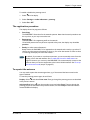
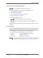
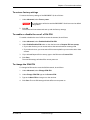
Safety summary
1
The following general safety precautions must be observed during all phases of operation, service
and repair of this equipment. Failure to comply with these precautions or with specific warnings
elsewhere in this manual violates safety standards of design, manufacture and intended use of the
equipment. Cobham SATCOM assumes no liability for the customer's failure to comply with these
requirements.
Do not operate in an explosive atmosphere
Do not operate the equipment in the presence of flammable gases or fumes. Operation of any
electrical equipment in such an environment constitutes a definite safety hazard.
Keep away from live circuits
Operating personnel must not remove equipment covers. Component replacement and internal
adjustment must be made by qualified maintenance personnel. Do not replace components with
the power cable connected. Under certain conditions, dangerous voltages may exist even with the
power cable removed. To avoid injuries, always disconnect power and discharge circuits before
touching them.
Do not service alone
Do not attempt internal service or adjustments unless another person, capable of rendering first aid
resuscitation, is present.
Do not substitute parts or modify equipment
Because of the danger of introducing additional hazards, do not substitute parts or perform any
unauthorized modification to the equipment.
Keep away from antenna front
This device emits radio frequency energy when switched on. To avoid
injury, keep a minimum safety distance of 1 m from the antenna front
when the EXPLORER 710 is on.
For information on the safety distance from the transceiver (WLAN), see
the FCC/IC Radiation Exposure statement on the next page.
Garder à l'écart de l'avant de l'antenne
Le présent appareil émet des radiofréquences lors de son utilisation. Afin d'éviter tout risque pour la
santé, une distance minimale de 1 m est nécessaire entre l'utilisateur et l'avant de l'EXPLORER 710.
Pour plus d'informations à propos de la distance de sécurité avec l'appareil (WLAN), veuillez
consulter Déclaration de l’IC sur l'exposition aux radiations sur la page suivante.
Only use approved batteries from Cobham SATCOM
Use of non approved batteries may result in explosion, fire, electrical shock or injury.
Observe marked areas
Under extreme heat conditions do not touch areas of the EXPLORER 710
that are marked with this symbol, as it may result in injury.
The terminal has been designed for full usability meaning that there are
no restrictions to which interfaces can be used simultaneously. This
means that you can use all the interfaces at once at any temperature
98-140012-D
iii
within -25 to 55 °C. Be aware that the terminal will get very hot when it is operated at 55 °C with all
interfaces active and it is therefore marked with a heating label.
FCC/IC Radiation Exposure statement
WLAN: Transceiver Unit (when separated from the Antenna Unit):
This equipment complies with FCC and IC radiation exposure limits for an uncontrolled environment. This
equipment should be installed and operated at a distance greater than 20 centimeters (8 inches) between
the transceiver unit and yourself or any bystander to comply with the Radiation Exposure Requirements.
Déclaration de l’IC sur l'exposition aux radiations
WLAN: L'émetteur-récepteur (quand séparé de l'antenne) :
Le présent appareil est conforme aux limites de l’IC sur l'exposition aux rayonnements établies pour un
environnement non-contrôlé. Le présent appareil doit être installé et utilisé à une distance minimum de
20 centimètres (8 pouces) entre l'émetteur-récepteur et l'utilisateur ou tout autre individu pour être
conforme à la réglementation en matière d'exposition radiologique.
Safety note from battery supplier
Korean text:
전지
경고 : 발열 , 화재 , 폭발등의 위험을 수반할 수 있으니 다음 사항을 지켜주시기 바랍니다 .
•
화기에 가까이 하지 말 것
•
분해 , 압착 , 관통 등의 행위를 하지 말 것
•
높은 곳에서 떨어뜨리는 등 비정상적 충격을 주지 말 것
•
전지 단자에 목걸이 , 동전 , 열쇠 , 시계 등 금속 제품이 닿지 않도록 주의할 것 ( 휴대컴퓨
터용 전지가 아닌 경우 생략 가능 )
•
60°C 이상의 고온에 노출하지 말 것
휴대 기기 , 제조업체가 보증한 리튬 2 차전지 사용할 것
English translation:
Battery
Warning: Hazards such as high temperature, fire or explosion can happen. To avoid such hazards, observe
the following directions and recommendations.
•
Keep away from fire.
•
Do not disassemble, break or penetrate the battery.
•
Do not drop the battery.
•
Do not touch the terminals of the battery with conductive materials such as coins, keys, watches etc.
•
Do not expose the battery to temperatures above 60 C.
•
Only use Li-Ion batteries that are approved by the manufacturer.
98-140012-D
iv
Antenna safety instructions
Antenna safety instructions
2
Use only manufacturer supplied antennas.
Antenna minimum safe distance: 1 m
Antenna gain
Directional, with maximum gain of 14.6 dB with reference to isotropic.
The Federal Communications Commission has adopted a safety standard for human
exposure to RF (Radio Frequency) energy which is below the OSHA (Occupational Safety
and Health Act) limits.
Antenna mounting
The antenna supplied by the manufacturer must be located such that during radio
transmission, no person or persons can come closer than the above indicated minimum
safe distance to the front face of the antenna, i.e. 1 m.
L'antenne fournie par le fabricant doit être placée de telle sorte que, durant les
transmissions radio, personne ni aucun groupe de personnes ne puisse s'approcher à une
distance inférieur à la distance de sécurité minimal indiquée ci-dessus, c.-à-d., 1 m.
To comply with current FCC RF Exposure limits, the antenna must be installed at or
exceeding the minimum safe distance shown above, and in accordance with the
requirements of the antenna manufacturer or supplier.
Antenna substitution
Do not use any other antenna than the models supplied or recommended by the
manufacturer. You may be exposing people to excess radio frequency radiation. You
may contact the manufacturer for further instructions.
Radiation warning
WARNING! Maintain a separation distance of at least 1 m from the front
face of the antenna to a person.
You, as the qualified end-user of this radio device, must control the exposure conditions
of bystanders to ensure the minimum separation distance (above) is maintained
between the antenna and nearby persons, for satisfying RF Exposure compliance. The
operation of this transmitter must satisfy the requirements of General Population/
Uncontrolled Environment. Only use the terminal when persons are at least the
minimum distance from the front face of the antenna.
98-140012-D
v
About this manual
About this manual
3
Intended readers
This manual is a user manual for the EXPLORER 710. The manual is intended for anyone
who is using or intends to use the EXPLORER 710. No specific skills are required to
operate the EXPLORER 710. However, it is important that you observe all safety
requirements listed in the Safety summary in the beginning of this manual, and
operate the EXPLORER 710 according to the guidelines in this manual.
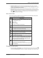
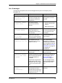
Related documents
The following documents are related to this manual and to the EXPLORER 710 system.
Title and description
Document
number
EXPLORER 710 Getting Started, English
98-139653
EXPLORER 710 Getting Started, Deutsch (German)
98-140216
EXPLORER 710 Getting Started, Français (French)
98-140217
EXPLORER 710 Getting Started, Español (Spanish)
98-140218
EXPLORER 710 Getting Started, Русский (Russian)
98-140219
EXPLORER 710 Getting Started, 中文 (Chinese)
98-140220
EXPLORER 710 Getting Started, 日本語 (Japanese)
98-140221
Typography
In this manual, typography is used as indicated below:
Bold is used for the following purposes:
•
To emphasize words.
Example: “Do not touch the antenna front during pointing”.
•
To indicate what the user should select in the user interface.
Example: “Select Control panel > LAN and click Enable”.
Italic is used to emphasize the paragraph title in cross-references.
Example: “For further information, see Connecting Cables on page...”.
98-140012-D
vi
Table of Contents
Chapter 1 Introduction to EXPLORER 710
General description .................................................................................................................. 1
Features and interfaces of the EXPLORER 710 ............................................. 2
Your EXPLORER 710 terminal ......................................................................................... 4
Chapter 2 To get started
To unpack and assemble the EXPLORER 710 .................................................. 8
Cable connections ...................................................................................................................13
To start up the EXPLORER 710 ....................................................................................15
To connect to the WLAN interface .........................................................................19
To connect to the LAN interface ..............................................................................20
To connect your phone to the EXPLORER 710 ............................................21
To make the first call or data session ..................................................................25
Fixed antenna installation ...............................................................................................28
Chapter 3 To use the EXPLORER 710
User interfaces ............................................................................................................................29
Data connection with computer, smartphone or tablet ....................31
Phone connection ....................................................................................................................38
To charge your smartphone or tablet ..................................................................40
To see alerts ..................................................................................................................................41
Terminal settings in display ...........................................................................................41
To see properties of the EXPLORER 710 in the display ......................42
Tracking .............................................................................................................................................42
Chapter 4 To use the web interface
The EXPLORER Connect app ..........................................................................................44
The web interface ....................................................................................................................44
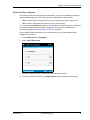
To enter the SIM PIN in the web interface ...................................................47
To point the antenna (BGAN) .......................................................................................48
To control data connections from web interface .....................................49
98-140012-D
vii
Table of Contents
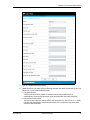
Status information ..................................................................................................................51
The Control panel ....................................................................................................................51
To use the logs ............................................................................................................................52
Battery status information .............................................................................................53
To set up the interfaces ....................................................................................................54
To manage IP handsets or smartphones ...........................................................58
Support features .......................................................................................................................59
Terminal settings ......................................................................................................................62
To set up your data connection packages .......................................................67
Multiple data connections ..............................................................................................69
To set up tracking ....................................................................................................................74
Advanced settings ...................................................................................................................76
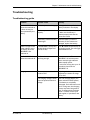
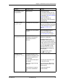
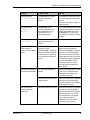
Chapter 5 Maintenance and troubleshooting
To get support .............................................................................................................................89
Software update ........................................................................................................................90
Maintenance .................................................................................................................................92
Troubleshooting ........................................................................................................................95
Log files ...........................................................................................................................................106
App. A
Technical specifications
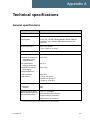
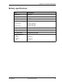
General specifications ......................................................................................................107
Battery specifications .......................................................................................................108
Interfaces specifications ...............................................................................................109
Detachable BGAN antenna specifications ....................................................114
Satellite coverage .................................................................................................................115
App. B
Conformity
General .............................................................................................................................................116
CE (R&TTE) ...................................................................................................................................116
IC ..........................................................................................................................................................116
FCC ......................................................................................................................................................117
98-140012-D
viii
Table of Contents
Glossary
...................................................................................................................................................................119
Index
...................................................................................................................................................................123
98-140012-D
ix
Chapter 1
Introduction to EXPLORER 710
1
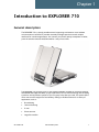
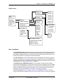
General description
The EXPLORER 710 is a handy portable terminal supporting simultaneous voice and data
communication over BGAN. It provides versatility and high speed access with multiple
interfaces for countless applications. Just connect your phone, laptop, smartphone or tablet,
point the antenna towards the BGAN satellite - and you are online.
The EXPLORER 710 provides access to the highest bandwidth available on the BGAN network.
With BGAN HDR (High Data Rate) you get a portfolio of four channel streaming rates including
symmetric and asymmetric options so you only pay for the data you need. The system offers
multi-user as well as single-user functionality, making it a flexible solution for a variety of
applications, such as:
•
Broadcasting
•
Internet browsing
•
E-mail
•
Phone services
•
Large file transfers
98-140012-D
General description
1
Chapter 1: Introduction to EXPLORER 710
•
Video conference and Streaming
•
VPN (Virtual Private Network) access to corporate servers
The EXPLORER 710 can withstand severe environmental conditions such as humidity, dust,
extreme weather and changing temperatures. It is small in size and fits easily into a backpack
or similar. With the detachable antenna it is well suited for temporary camps or fixed
installations.
Features and interfaces of the EXPLORER 710
Features
Full duplex, single or multi-user, standard data up to 492 kbps
Support for streaming data at 32, 64, 128, 176, 256 kbps, HDR (asymmetric or symmetric)
and BGAN X-Stream
Standard LAN w. PoE, WLAN, ISDN and Phone ports and USB Host interface
Detachable antenna with integrated transceiver stand and transceiver-to-antenna range up
to 100 m/328 ft.
Built-in DHCP/NAT wireless router
Solar panel direct interface
Support for battery hot swap
10-32 VDC input
100-240 VAC power adapter
Built-in web interface allowing you to manage your calls and customize the terminal to your
specific needs, using a smartphone, computer or tablet.
Support for the EXPLORER Connect smartphone app allowing you to use your phone as a
satellite phone and to access the settings of the terminal.
Advanced network management
Point-to-Point Protocol over Ethernet (PPPoE)
Built-in PBX and SIP server managing voice communication
Remote management and remote access
Multilingual user interface (English, French, German, Russian, Spanish, Chinese, Japanese)
CE, FCC, GMPCS and IC certified
98-140012-D
Features and interfaces of the EXPLORER 710
2
Chapter 1: Introduction to EXPLORER 710
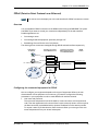
Overview of interfaces
The EXPLORER 710 provides a number of interfaces for connection of various types of
computers, phones and other equipment.
Smartphone
Tablet
WLAN
LAN
ISDN or
Phone
To get started on page 8 describes how to use each of the available interfaces.
To minimize power consumption
The EXPLORER 710 is designed for minimum power consumption. This means that functions
that are not currently used will automatically go into a “sleep mode” to minimize the power
consumption. In addition to this automatic sleep mode function, you can disable each of the
interfaces if they are not currently used. Note, however, that you will not be able to use these
interfaces until you enable them again. For information on how to enable/disable interfaces,
see To enable or disable an interface on page 30.
98-140012-D
Features and interfaces of the EXPLORER 710
3
Chapter 1: Introduction to EXPLORER 710
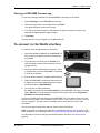
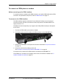
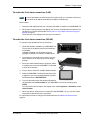
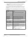
Your EXPLORER 710 terminal
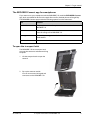
Overview
The EXPLORER 710 is a compact unit comprising a transceiver with a detachable antenna,
compass, display and keypad, all in one unit.
Transport lock
Antenna
for BGAN
and GNSS
Antenna for
Wireless LAN
Display and
keypad
Battery
98-140012-D
SIM card
(behind the battery)
Your EXPLORER 710 terminal
Compass
Connectors
4
Chapter 1: Introduction to EXPLORER 710
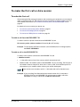
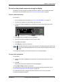
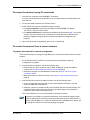
Display and keypad
The EXPLORER 710 has a display and keypad providing quick access to important functions and
simple setup, and for displaying status.
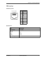
3
4
2
9
5
6
7
1
8
1. Menu: Opens the display menu. For a menu overview, see next page.
2. Connect: Allows you to start a data connection.
3. Signal strength: Shows the signal strength of the satellite connection and whether the
connection is global beam (G), regional beam (R) or narrow beam (N). Press OK to see the
GNSS position.
4. Interfaces on/off: Allows you to switch the interfaces on or off. Disabled interfaces are
crossed out.
5. Warning: Shows if there are alerts. Press OK to see the alerts.
6. Battery status: Shows remaining time for the internal battery and the external battery (if
connected).
7. Keypad for navigation: Allows you to move between the available options (arrow keys) and
select them (OK).
8. Status indicator: Shows status of the EXPLORER 710. For information on functions, see
Status indicator on page 101.
9. Status text: Shows the current status of the EXPLORER 710 and the network connection.
For example, the text may show the status during start-up (see The registration procedure
on page 18).
To navigate the display functions
•
To highlight one of the icons, use the arrow buttons.
•
To move around between the icons, use the arrow buttons.
•
To select menu items, functions or values, press the OK key.
98-140012-D
Your EXPLORER 710 terminal
5
Chapter 1: Introduction to EXPLORER 710
Display menu
%ULJKWQHVV
7LPHRXW
([LW
3RLQWQRZ
6HWWLQJV
3URSHUWLHV
+HOSGHVN
$OHUWV
3RLQWLQJ
'LVSOD\
$XGLRLQGLFDWLRQ
3RZHUXSPRGH
/DQJXDJH
,3DGGUHVV
+DUGZDUH
6RIWZDUH
&RQIRUPLW\
,0(,
$XWRPDWLF
0DQXDO
(QJOLVK
)UDQoDLV
'HXWVFK
Ɋɭɫɫɤɢɣ
(VSDxRO
୰ᩥ
᪥ᮏㄒ
/HYHO
/HYHO
/HYHO
/HYHO
/HYHO
/HYHO
/HYHO
VHFRQGV
VHFRQGV
PLQXWH
PLQXWHV
PLQXWHV
2Q
2II
8QLWVHULDOQXPEHU
$QWHQQDVHULDOQXPEHU
0$&IRU/$1
0$&IRU:/$1
User interfaces
The keypad and display described in the previous section are used for pointing the antenna,
starting and stopping data sessions, enabling or disabling interfaces and for displaying status
and changing simple parameters. To obtain full access to all features and for ease-of-use, you
should use a computer or smartphone and the web interface.
The web interface is a built-in web interface for easy configuration and daily use. The web
interface is accessed from a computer, smartphone or tablet connected to the EXPLORER 710,
using an Internet browser. No installation of software is needed. For further information on the
web interface, see To use the web interface on page 43.
A smartphone app, EXPLORER Connect, is also available. The app includes a satellite
phone function that enables you to make calls to and from your smartphone over the satellite
network using the EXPLORER 710 terminal. It also includes the complete feature set from the
built-in web interface of the terminal, allowing you to set up and use the terminal with your
smartphone. See The EXPLORER Connect app for smartphones on page 9.
With AT commands you can configure and control the EXPLORER 710 from a computer
using a Telnet session. For details see To access the terminal using AT commands on page 36.
98-140012-D
Your EXPLORER 710 terminal
6
Chapter 1: Introduction to EXPLORER 710
Antenna
The white part of the EXPLORER 710, including the support bracket, is the detachable antenna
module. The antenna module comprises a GNSS (Global Navigation Satellite System) antenna
and a BGAN antenna.
A Wireless LAN antenna is located on the transceiver unit.
Compass
The EXPLORER 710 also provides a compass to help positioning the antenna. For further
information on how to use the compass, see To point the antenna on page 16.
Battery
The EXPLORER 710 comes with a rechargeable battery, which is easily inserted. The battery is
automatically recharged when power is applied to the EXPLORER 710. The Status indicator
shows that the battery is charging. See Status indicator on page 101.
Time between recharging depends on the use. The display shows estimated time left for the
battery.
SIM card
The EXPLORER 710 requires a SIM card to go online. Without a SIM card you can still configure
the terminal and you may be able to make emergency calls if the network allows it, but you
cannot make normal calls nor access the internet.
SIM lock: The supplier may have locked the SIM card to a specific provider. For further
information, contact your supplier.
98-140012-D
Your EXPLORER 710 terminal
7
Chapter 2
To get started
2
This chapter describes:
•
To unpack and assemble the EXPLORER 710
•
Cable connections
•
To start up the EXPLORER 710
•
To connect to the WLAN interface
•
To connect to the LAN interface
•
To connect your phone to the EXPLORER 710
•
To make the first call or data session
•
Fixed antenna installation
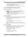
To unpack and assemble the EXPLORER 710
Initial inspection
Inspect the shipping carton immediately upon receipt for evidence of damage during
transport. If the shipping carton is severely damaged or water stained, request that the carrier's
agent be present when opening the carton. Save the carton packing material for future use.
WARNING! To avoid electric shock, do not apply power to the system if there is
any sign of shipping damage to any part of the front or rear panel or the outer
cover. Read the safety summary at the front of this manual before installing or
operating the system.
After unpacking the system, inspect it thoroughly for hidden damage and loose components or
fittings. If the contents are incomplete, if there is mechanical damage or defect, or if the
system does not work properly, notify your dealer.
What’s in the delivery
The following items are included in the delivery:
•
EXPLORER 710 terminal including transceiver, antenna and antenna cable
•
Battery pack
•
AC/DC adapter
•
Getting started kit including:
• Ethernet/ISDN cable, 2 m screened
• Getting started booklet
98-140012-D
To unpack and assemble the EXPLORER 710
8
Chapter 2: To get started
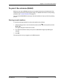
The EXPLORER Connect app for smartphones
If you want to use your smartphone with the EXPLORER 710, install the EXPLORER Connect
app, which is available for iPhone at the Apple Store and for Android phones at Google Play.
The EXPLORER Connect app provides the following options from the main menu:
Tile
Function
Satellite Phone
Use your phone as a satellite phone when connected to the
EXPLORER 710
Terminal Access
Start and stop data connections and
access all settings of the EXPLORER 710
Pointing
Activate the pointing process for the EXPLORER 710 towards the
BGAN satellite
Dashboard
See the terminal and connection status
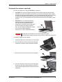
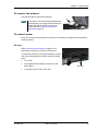
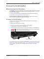
To open the transport latch
The EXPLORER 710 has a transport latch,
securing the transceiver and antenna during
transport.
1. Lift the transport latch to open the
terminal.
2. Flip up the antenna module.
You can now access the keypad and
connectors on the EXPLORER 710.
98-140012-D
To unpack and assemble the EXPLORER 710
9
Chapter 2: To get started
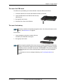
To detach the antenna (optional)
You have two options for using the EXPLORER 710 antenna:
•
Attached. You can go through the pointing process with the antenna and transceiver
attached as one unit. This means you have to move the entire terminal in order to point
the antenna towards the BGAN satellite. If you choose this option, make sure you connect
all cables including the short antenna cable, and enter the PIN, before pointing the
antenna. If not, you may accidently move the antenna when you connect cables or enter
the PIN.
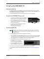
•
Detached. You can detach the antenna
module and use it as a separate antenna.
With the antenna separated from the
transceiver, it is easier to use the transceiver
without accidently moving the antenna.
Also, you can choose the optimum location
for the antenna while keeping the
transceiver in a more comfortable location.
Important
Antenna
Transceiver
Do not place the transceiver in front of the antenna module!
The antenna emits radio frequency energy, which can affect the transceiver.
To detach the antenna, do as follows:
1. Locate the slide locks on the bottom of the terminal.
2. Press and slide the locks outwards while lifting the
transceiver to release it from the antenna bracket.
3. Remove the transceiver from the antenna bracket.
4. To move the antenna and transceiver further apart,
disconnect the short antenna cable and connect a
longer antenna cable between the antenna and the
transceiver.
98-140012-D
To unpack and assemble the EXPLORER 710
10
Chapter 2: To get started
To insert the SIM card
The SIM card is provided by your Airtime Provider. Insert the SIM card as follows:
1. Locate the SIM slot on the same side where the battery is inserted.
2. Insert the SIM card into the SIM slot with the chip
side facing up.
3. Press gently until it clicks.
4. Slide the lock in front of the SIM slot.
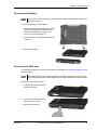
To insert the battery
Note
The battery should not be partially charged too often. For further information on the
battery, see Maintenance on page 92.
Do as follows:
1. Insert the battery so that the connector fits into
the battery slot, indicated in the figure.
2. Press gently until it locks.
Note
Before using the terminal the first time: to ensure accurate information on the battery
capacity you should fully charge, then fully discharge the battery, and finally recharge
the battery while it is inserted in the terminal. The EXPLORER 710 can be used during
the discharging process, but the remaining battery capacity may not be displayed
correctly.
For information on how to recharge the battery, see To recharge batteries on
page 92
98-140012-D
To unpack and assemble the EXPLORER 710
11
Chapter 2: To get started
To remove the battery
Note
For protection of the transceiver, always leave the battery inserted. Only remove the
battery to replace it.
To remove the battery, do as follows:
1. If the transceiver and antenna are attached,
open the transport latch and detach the
antenna as described in To detach the
antenna (optional) on page 10.
2. On the transceiver, open the battery latches
as shown.
3. Remove the battery.
To remove the SIM card
To remove the SIM card, first remove the battery as described in To remove the battery in the
previous section.
Note
When the SIM card is removed you cannot make calls or data sessions, but you can
still use the display menu system and the built-in web interface to set up the terminal.
Remove the SIM card as follows:
1. Slide the lock aside to open the
SIM slot as shown.
2. Gently press the SIM card and
let it pop out of the slot.
3. Remove the SIM card.
98-140012-D
To unpack and assemble the EXPLORER 710
12
Chapter 2: To get started
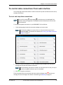
Cable connections
Connectors
The connector panel is placed on the side of the EXPLORER 710 and has the following
connectors:
External battery
DC in
Phone
LAN2
LAN1 ISDN
(PoE)
•
1 Ext battery connector for connecting an extra EXPLORER 710 battery.
See To connect an extra, external EXPLORER 710 battery on page 93.
•
1 DC power input connector for 10 - 32 VDC.
See To connect power on page 14.
•
1 Phone connector.
See To connect an analogue phone on page 23.
•
2 LAN connectors, one with PoE.
See To connect to the LAN interface on page 20 and
To connect a phone using LAN or WLAN on page 21.
•
1 ISDN connector.
See To connect an ISDN phone or modem on page 24.
Apart from the connectors in the connector panel, there is:
•
•
98-140012-D
1 USB (Host) connector placed next
to the Power button.
The USB (Host) connector is primarily
used for charging phones or tablets
(up to 2 A) and for recovery update of
software.
See To charge your smartphone or
tablet on page 40 and
To update software with USB on
page 90.
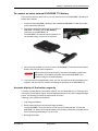
Antenna
USB (Host)
1 antenna connector for connecting the antenna module of the EXPLORER 710.
See the next section.
Cable connections
13
Chapter 2: To get started
To connect the antenna
The antenna cable is connected at delivery.
Note
If you want to use the antenna separated from
the transceiver, use a longer antenna cable and
remove the transceiver from the antenna
bracket. See the To detach the antenna
(optional) on page 10.
To connect power
When you connect external power to the DC input, the battery is charged while maintaining
normal operation.
DC input
Refer to Technical specifications on page 107 for
specifications and pin-out for the DC Power input.
To power the terminal or to charge the battery, connect
one of the following external power sources to the DC
input:
•
10-32 VDC
•
The supplied AC/DC adapter connected to 100240 V Mains
•
A solar panel (min. 65 W, 10-32 VDC)
98-140012-D
Cable connections
DC input
14
Chapter 2: To get started
To start up the EXPLORER 710
Automatic power up
The default behaviour of the EXPLORER 710 is to power up automatically when you connect
external power. If you wish, you can change this power up mode, so that the EXPLORER 710 is
only powered if the Power button is pressed.
For further information on power up mode, see Automatic power up on page 41.
To switch the EXPLORER 710 on or off
1. Slide and hold the power button until the Status
indicator lights up. This may take some seconds.
2. When the Status indicator flashes slowly or is
constant green, and the display shows Ready, the
terminal is ready for use.
3. To switch off, hold the power button until the
Status indicator flashes yellow.
This may take some seconds.
To enter the SIM PIN
Note
You may not need a SIM PIN for your terminal. If you are asked for a PIN and you
select Cancel, you cannot communicate on the BGAN network, but you can access
all terminal settings.
To enter the SIM PIN using the display and keypad, do as follows:
1. When the display shows Enter PIN?, highlight the text using the arrow keys and press OK.
If you select Cancel, the startup procedure is continued, but you will not be able to make
calls or data sessions over the satellite network. See the previous section.
2. Press or a number of times until the first digit is correct.
3. Press OK to go to the next digit.
The previous digit is indicated by a *.
4. After pressing OK to enter the last
digit, press OK again to apply the PIN.
For an overview of the display and keypad, see Display and keypad on page 5.
For information on how to enter the PIN in the web interface, see To enter the SIM PIN on
page 47.
98-140012-D
To start up the EXPLORER 710
15
Chapter 2: To get started
To point the antenna
Note
You can choose to cancel pointing. In this case you cannot communicate on the
BGAN network, but you can access all terminal settings.
Before pointing
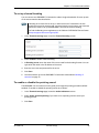
Before pointing the antenna you can use the coverage map below to find your approximate
location in relation to the satellites. Then you can use the compass to find the pointing
direction to the closest satellite.
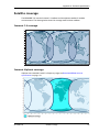
The 3 Inmarsat satellites are positioned above the equator, at the centre of each “footprint”.
90°
80°
70°
60°
50°
40°
30°
20°
10°
0°
10°
20°
30°
40°
50°
60°
70°
80°
90°
180°
98-140012-D
160°
140°
120°
100°
80°
60°
40°
20°
0°
20°
To start up the EXPLORER 710
40°
60°
80°
100°
120°
140°
160°
180°
16
Chapter 2: To get started
To point the antenna
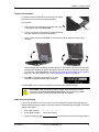
To obtain optimum bandwidth and operating time, adjust
the position of the antenna with great precision.
Do as follows:
1. If the terminal is not already in pointing mode, select
in the display and select Point now.
Compass
2. Use the compass to locate the approximate direction
from the antenna front face to the satellite.
3. Slowly rotate and tilt the EXPLORER 710 antenna to find the highest possible signal
strength.
Use the display and the pointing sound to guide you. Remember that the more accurately
the terminal is aligned, the better throughput and lower power consumption you will get!
You may also use the EXPLORER Connect app, see Pointing in EXPLORER Connect app on
page 19, or the web interface, see To point the antenna (BGAN) on page 48.
4. Press OK on the display keypad when you have
obtained the highest possible signal strength.
The EXPLORER 710 now starts to establish a connection to the BGAN network.
CAUTION! After accepting the signal strength, keep the minimum safety
distance of 1 m from the antenna front face. The antenna may radiate
microwave power as soon as the signal strength is accepted.
Audio assisted pointing
You can set up whether or not you want a sound to indicate the signal level during pointing
(Audio assisted pointing), to help you find the maximum obtainable signal strength. The sound
pattern is as follows:
•
Poor signal strength:
•
•
Good signal strength:
•••••••••••••••••••
•
Optimum signal strength:
98-140012-D
•
•
•
(continuous sound instead of single “beeps”)
To start up the EXPLORER 710
17
Chapter 2: To get started
To enable or disable the pointing sound:
1. Select in the display.
2. Select Settings > Audio indication > pointing.
3. Select On or Off.
The registration procedure
The display shows the progress as follows:
•
Searching:
The EXPLORER 710 searches for the network operator. Note that the search procedure can
be very short, so you may not see this text.
•
Registering:
The EXPLORER 710 is registering itself on the network.
If the GNSS position has not yet been acquired at this point, the display may show No
position.
•
Ready (or other status information):
Ready means the EXPLORER 710 is registered on the network and is ready to go online. If
there is any other status information to show, e.g. if a call or data session is active or there
is a warning, the display will show that instead.
Note
By default, if you want to use a data connection, you must manually start it from the
display or from the web interface. See To make the first call or data session on
page 25. However, you can set up the EXPLORER 710 to automatically connect to the
Internet when you connect equipment to the LAN or WLAN interface. See To set up
the connection mode (step 4. on page 65).
To repoint the antenna
You may need to point the antenna again later, e.g. if the terminal has been moved or the
signal is blocked.
To start the pointing process again, do as follows:
Display: Select and select Point now. Then go through the pointing process as described
in the previous section.
web interface: Select from the top right corner and select Start. Then go through the
pointing process as described in the previous section, but click Accept in the web interface
instead of OK in the display.
98-140012-D
To start up the EXPLORER 710
18
Chapter 2: To get started
Pointing in EXPLORER Connect app
To start the pointing procedure from the EXPLORER Connect app, do as follows:
1. Select Pointing from the EXPLORER Connect app.
2. If the pointing process is not already started, tap Start.
The signal strength is shown on the screen.
3. Turn and tilt the antenna slowly as described in the previous sections until you have
obtained the highest possible signal strength.
4. Tap Accept.
The terminal will now try to register on the BGAN network.
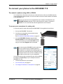
To connect to the WLAN interface
To connect to the WLAN interface, do as follows:
1. Check that WLAN is enabled in your EXPLORER 710.
The top line of the display shows which interfaces
are enabled.
2. If your device is not close to the EXPLORER 710,
turn the WLAN antenna of the transceiver into an
upright position.
3. Place your WLAN-enabled device (computer, tablet
or smartphone) close to the EXPLORER 710, but not
in front of the antenna.
4. On your device, search for available WLAN networks.
5. Select the EXPLORER 710 WLAN access point when
it appears in your list of available wireless networks.
The default name is EXPLORER710.
6. You may have to enter a password.
By default, the password is the serial number of your EXPLORER 710 and the encoding
type is WPA2. You can find the serial number in the display menu under Properties >
Hardware > Unit serial number.
Your device should now be connected to the EXPLORER 710. If you want to connect to the
Internet, you must start a data connection, see To start or stop a data connection using the
display on page 27. The status text in the display shows when there is an active data
connection.
You are now ready to browse the Internet, check e-mails, send files etc.
Calls: If you want to use WLAN to make calls over the BGAN network, you must have a SIP
client installed on your smartphone. See To connect a phone using LAN or WLAN on page 21.
For information on how to configure the WLAN interface, see WLAN interface setup on
page 54.
98-140012-D
To connect to the WLAN interface
19
Chapter 2: To get started
To connect to the LAN interface
Before connecting to the LAN interface
The EXPLORER 710 has two LAN connectors. If more than one LAN or WLAN user is connected
to the EXPLORER 710, the terminal should be in Router mode (default). Refer to To set up the
connection mode on page 63.
To connect to the LAN interface, use a shielded cable mounted with an RJ-45 connector.
For specifications, refer to LAN interface, 2-port on page 112.
For the LAN interface to work without any further setup, the computer must be set up to
obtain an IP address and a DNS server address automatically.
To connect to the LAN interface
This section does not describe configuration of the LAN interface. For information on
configuration, see on page 53.
To connect to the LAN interface, do as follows:
1. Connect the LAN cable to the network interface of your computer.
A suitable cable is provided with your EXPLORER 710.
2. Connect the other end of the cable to one of the LAN connectors on the EXPLORER 710.
Important
The ISDN interface and the LAN interface use the same connector type. Be
careful not to connect to the wrong interface.
LAN#1 and LAN#2
Your computer should now be connected to the EXPLORER 710. If you want to connect to the
Internet, you must start a data connection, see To start or stop a data connection using the
display on page 27. The status text in the display shows when there is an active data
connection.
98-140012-D
To connect to the LAN interface
20
Chapter 2: To get started
To connect your phone to the EXPLORER 710
To connect a phone using LAN or WLAN
Your smartphone or IP phone can be set up to make and receive calls over the BGAN network,
using the terminal’s phone number. You can also make local calls to other handsets connected
to the EXPLORER 710.
Note
Make sure your phone has an integrated SIP client. Cobham SATCOM offers the
EXPLORER Connect app with a built-in SIP client that is ready to use with the
EXPLORER 710. You can also find other SIP applications on the Internet.
To connect your smartphone for making calls
To use your phone to make calls through the EXPLORER 710 using WLAN, do as follows:
1. Start up the EXPLORER 710 terminal.
2. Connect your smartphone to the wireless access
point of the EXPLORER 710.
See To connect to the WLAN interface on page 19.
3. Start the EXPLORER Connect app and select
Satellite Phone (or start another SIP application).
If it is the first time you use the EXPLORER Connect
app, you must select Register when prompted.
Note
If you are using the EXPLORER Connect app for the
first time, make sure that “Enable Reception of
Incoming Calls” is selected in the settings page. This is
to prevent your smartphone from closing the WLAN
connection when not in use. This is necessary in order
to be able to receive calls on your smartphone.
You should now be ready to make and receive calls over BGAN.
For details on initial setup of your smartphone and the
EXPLORER 710, see
•
The documentation for your handset
•
First time SIP setup on page 22
•
To manage IP handsets or smartphones on page 58
98-140012-D
To connect your phone to the EXPLORER 710
21
Chapter 2: To get started
To connect a wired IP handset for making calls
Note
Make sure your IP handset complies with PoE class 2 (7 W).
For details on initial setup of your IP handset and the EXPLORER 710, see
•
The documentation for your handset
•
First time SIP setup on page 22
•
To manage IP handsets or smartphones on page 58
To connect a wired IP handset, do as follows:
1. Start up the EXPLORER 710 terminal.
Note
Make sure PoE is enabled in the terminal. See on page 53.
2. Connect the LAN cable between the IP handset and the connector LAN #1 on the
EXPLORER 710.
When the IP handset is powered and ready, you should now be able to make and receive calls
over BGAN.
First time SIP setup
If you do not have the EXPLORER Connect app and it is the first time you connect your phone
to the LAN or WLAN interface for making calls, you must first set up the SIP server details in
your smartphone. For information how, see the user documentation for your smartphone and
for the SIP application. You may be asked to enter some of the following details:
•
SIP server address and port: Default address: 192.168.0.1, Port: 5060
•
User name:
Local no. in EXPLORER 710 (0501 to 0516)
•
Password:
Default same as user name
•
Codec priority:
Highest priority codec type: G.711
Note
98-140012-D
The user name and password must match the IP handset settings in the web interface
of the EXPLORER 710. See To manage IP handsets or smartphones on page 58.
To connect your phone to the EXPLORER 710
22
Chapter 2: To get started
To connect an analogue phone
Before connecting to the Phone interface
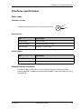
To connect a phone to the Phone connector, you need an analog telephone cable with an RJ11 connector. For specifications and pin-out, refer to Phone interface on page 110.
To connect to the Phone interface
Do as follows:
1. Connect the cable to your phone.
2. Connect the other end of the cable to the Phone connector on the EXPLORER 710.
3. Power up the EXPLORER 710 and point the antenna as described in To point the antenna
on page 16.
4. Check the connection by making a phone call.
See To make or receive a phone call with EXPLORER 710 on page 38.
If connection fails, check that the interface is enabled in the EXPLORER 710. If the analogue
phone icon is crossed out in the display main screen, the interface is disabled. See To enable or
disable an interface on page 30.
98-140012-D
To connect your phone to the EXPLORER 710
23
Chapter 2: To get started
To connect an ISDN phone or modem
Before connecting to the ISDN interface
To connect a phone or modem to the ISDN connector, you need an ISDN cable with an ISDN
connector. For specifications and pin-out, refer to ISDN interface on page 111.
To connect to the ISDN interface
The ISDN interface supports connection of up to 4 devices. However, if you are going to
connect more than one device, the devices must be self-powered. The ISDN interface can
supply maximum 1 W.
The BGAN Core network presently only supports one 64 kbps ISDN channel per subscription.
Do as follows:
1. Connect the ISDN cable to your phone or modem.
2. Connect the other end of the cable to the ISDN connector on the EXPLORER 710.
3. Power up the EXPLORER 710 and point the antenna as described in To point the antenna
on page 16.
4. Check the connection by making a phone call.
See To make or receive a phone call with EXPLORER 710 on page 38.
If connection fails, check that the ISDN interface is enabled in the EXPLORER 710.
If the ISDN icon is crossed out in the display main screen, the interface is disabled. See To
enable or disable an interface on page 30.
98-140012-D
To connect your phone to the EXPLORER 710
24
Chapter 2: To get started
To make the first call or data session
To make the first call
After entering the PIN, pointing the antenna and connecting your equipment, you are ready to
make or receive the first call. The following sections provide a short guide to making calls. For
more detailed information, see To make or receive a phone call with EXPLORER 710 on
page 38.
For details on how to connect your phone, see
•
To connect a phone using LAN or WLAN on page 21
•
To connect an analogue phone on page 23
•
To connect an ISDN phone or modem on page 24
To make a call from the EXPLORER 710
To make a call from a phone connected to the EXPLORER 710, dial
00 <country code> <phone number> followed by # or off-hook key.
Example: To call Cobham SATCOM in Denmark (+45 39558800) from an analogue phone,
dial 00 45 39558800 #
To make a call to the EXPLORER 710
To make a call to a phone connected to the EXPLORER 710, dial
+ <Mobile number>
•
+ is the prefix used in front of the country code for international calls.
•
Mobile number: The mobile number of the EXPLORER 710 you are calling. The first part of
the mobile number is always 870, which is the “country code” for the BGAN system. For
information on your mobile numbers, refer to your airtime subscription.
Note
There are two voice numbers, one for 3.1 kHz audio and one for Standard voice.
Example: If you are calling from Denmark and the mobile number for 3.1 kHz audio is
870782112345 on your EXPLORER 710, and you want to make a call to the
EXPLORER 710 using 3.1 kHz audio, dial 00 870 782112345.
98-140012-D
To make the first call or data session
25
Chapter 2: To get started
To make the first data connection (LAN)
Note
For the LAN interface to work without any further setup, your computer must be set
up to obtain an IP address and DNS server address automatically.
Do as follows:
1. Connect a LAN cable between your computer and LAN#1 or LAN#2 on the EXPLORER 710.
2. When power up and pointing is completed, you can start a Standard data connection from
the display or from the web interface. See To start or stop a data connection using the
display on page 27.
The status text in the display shows the active connection.
To make the first data connection (WLAN)
To connect to the WLAN interface, do as follows:
1. Check that WLAN is enabled in your EXPLORER 710.
The top line of the display shows which interfaces
are enabled.
If WLAN is disabled, use the keypad arrows to
highlight the WLAN icon and OK to enable WLAN.
2. If your device is not close to the terminal, turn the
WLAN antenna of the transceiver into an upright
position.
3. Place your WLAN-enabled device (computer, tablet
or smartphone) close to the EXPLORER 710, but not
in front of the antenna.
4. On your device, search for available WLAN networks.
5. Select the EXPLORER 710 WLAN access point when
it appears in your list of available wireless networks.
The default name is EXPLORER710.
6. If you are prompted, enter the password. By default,
the password is the serial number of your EXPLORER 710 and the encoding type is
WPA2.
You can find the serial number in the display menu under Properties > Hardware > Unit
serial number.
7. When your device shows that it is connected to the EXPLORER 710, you can start a data
connection as described in the next section.
For information on how to configure the WLAN interface, see WLAN interface setup on
page 54.
98-140012-D
To make the first call or data session
26
Chapter 2: To get started
To start or stop a data connection using the display
By default, you must manually start data connections. However, you can enable automatic
activation in the web interface. See To set up the connection mode on page 63.
To start a data connection
Do as follows:
1. Start up the terminal as described in To start up the EXPLORER 710 on page 15.
2. Connect your equipment to the interface you want to use.
3. Use the arrow keys to highlight the connection icon in the bottom left corner of the
display.
4. Push OK to see the available connection packages.
5. Go to the connection package you want to start or stop.
6. Push OK on the keypad.
7. Push OK again to start the connection.
Note
It may take some time to start up the connection. The display shows the status while
the connection is being established. If the connection fails, the display shows an error
message.
You should now be able to access the Internet from you connected device.
To stop a data connection
Do as follows:
8. Use the arrow keys to highlight the connection icon in the bottom left corner of the
display.
9. Push OK.
The running connection is displayed with Stop highlighted.
10. Push OK on Stop to stop the connection.
For information on how to start and stop data connections with the web interface, see To
control data connections from web interface on page 49.
For information on how to configure the data connections, see To set up your data
connection packages on page 67.
98-140012-D
To make the first call or data session
27
Chapter 2: To get started
Fixed antenna installation
You can keep the EXPLORER 710 antenna in a fixed position, using the Pole mount kit for
EXPLORER 710.
Do as follows:
1. Separate the antenna from the transceiver as described in To detach the antenna
(optional) on page 10.
2. Mount the EXPLORER 710 antenna on a pole or a wall, for example using the Pole mount
kit.
3. Connect the antenna cable between the antenna and the transceiver.
4. Start up the EXPLORER 710 and point the antenna as described in To point the antenna on
page 16.
5. Accept the signal strength by pressing OK on the EXPLORER 710 keypad.
6. Fasten the EXPLORER 710 antenna in the pointed position.
You only have to point the antenna once, when you mount it. Using a computer connected to
the EXPLORER 710, you can set up the EXPLORER 710 to skip pointing at power up. Refer to
Pointing at start-up on page 63.
98-140012-D
Fixed antenna installation
28
Chapter 3
To use the EXPLORER 710
3
This chapter describes daily use and basic setup using the display. For information on the web
interface, see To use the web interface on page 43.
This chapter describes:
•
User interfaces
•
Data connection with computer, smartphone or tablet
•
Phone connection
•
To see alerts
•
Terminal settings in display
•
To see properties of the EXPLORER 710 in the display
•
Tracking
User interfaces
The following user interfaces are available when using the EXPLORER 710
•
Phone
•
ISDN
•
LAN
•
WLAN
•
USB (Host)
98-140012-D
User interfaces
29
Chapter 3: To use the EXPLORER 710
To enable or disable an interface
To enable or disable interfaces with the display and keypad
Note
By default, only the LAN interface is enabled. However, you can enable or disable each
of the interfaces independently.
To enable or disable an interface, do as follows:
1. In the top of the display, locate the interface you want to enable or disable.
WLAN ISDN LAN
Phone
USB
2. Use the arrow keys on the keypad to highlight the interface you want to enable or disable.
3. Press OK to toggle between enable and disable.
The interface is greyed and crossed out when disabled.
Note
It may take some seconds to enable an interface. When the icon stops pulsating
and is no longer crossed out, the interface is enabled.
To enable or disable interfaces with the web interface
Note
By default, only the LAN interface is enabled. However, you can enable or disable each
of the interfaces independently.
To enable or disable an interface using the web interface, do as follows:
1. Connect your smartphone, tablet or computer to the EXPLORER 710, using the LAN or
WLAN interface. See:
• To connect to the LAN interface on page 20
• To connect to the WLAN interface on page 19
2. To access the web interface, open your browser and type the IP address of your
EXPLORER 7101 (default IP address: 192.168.0.1).
For further information on the web interface, see To use the web interface on page 43.
1. You find the IP address in the display menu system by entering the menu and selecting
Properties > IP address.
98-140012-D
User interfaces
30
Chapter 3: To use the EXPLORER 710
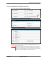
3. When the web interface opens, click ?(Control panel) from the bottom right corner of the
page.
4. Locate the tile with the interface you want to enable or disable.
• ?means the interface is disabled.
• ?means the interface is enabled.
5. To enable or disable the interface, click the tile and select or clear Enable.
6. Click Save.
Note
It may take some seconds to enable the interface. When the icon changes to the
enabled icon shown in step 4. above, the interface is enabled.
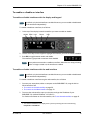
Data connection with computer, smartphone or tablet
Overview
The following interfaces are available for connecting computers, smartphones or tablets:
•
WLAN
•
LAN
To choose an interface for data connection
The following table shows some characteristics of each interface to help you choose the right
interface for your application. For information on how to connect your equipent, see To
connect to the WLAN interface on page 19 and To connect to the LAN interface on page 20.
Interface
Power
consumption
WLAN
High
LAN
High
Amount of setup
Range
Some setup necessary on
your WLAN device and in
the web interface of the
EXPLORER 710
Wireless connection.
None (or very little)
Up to 100 m of cable
Up to 100 m depending on the
transmitter in the computer and
on the transmission conditions.
Router function
The terminal has a router function which routes traffic between the local network connected
to the terminal and up to 11 BGAN network connections (also called PDP contexts on the
BGAN network).
The router contains NAT (Network Address Translation) which allows sharing of a public IP
address between a number of local network users.
98-140012-D
Data connection with computer, smartphone or tablet
31
Chapter 3: To use the EXPLORER 710
Standard or Streaming data
The BGAN network supports different classes of data connection to the Internet. The main
classes are Standard data and Streaming data.
•
Using a Standard data connection, several users can share the data connection
simultaneously. This type of connection is ideal for TCP/IP traffic such as e-mail, file
transfer, and Internet and intranet access.
The user pays for the amount of data sent and received.
•
Using a Streaming data connection, you get an exclusive, high-priority connection,
ensuring seamless transfer of data. This type of connection is ideal for time critical
applications like live video over IP.
The user pays for the duration of the connection (per minute charge).
To start or stop a data connection
By default, you must manually start data connections. However, you can enable automatic
activation in the web interface. See To set up the connection mode on page 63.
Display: For information on how to start and stop data connections using the display, see To
start or stop a data connection using the display on page 27.
Web interface: For information on how to start and stop data connections with the web
interface, see To control data connections from web interface on page 49.
Configuration: For information on how to configure the data connections, see To set up
your data connection packages on page 67.
Bonding of terminals
You can connect two EXPLORER 710 terminals to obtain a higher bandwidth. This is useful for
UDP connections such as video and audio transmissions.
Note
A bonding server must first be set up, in order receive and “reassemble” the two
signals into one at the receiving end. You must know the server name, user name and
password in order to set up the EXPLORER 710 terminals used for bonding.
You find the Bonding server application in the Cobham SATCOM Self Service Center
at http://esupport.thrane.com/?group=SSC.
Do as follows:
1. Configure the bonding settings on both terminals as described in To set up channel
bonding on page 66. Make sure bonding is enabled for both terminals.
2. Make sure both terminals are in Router mode (see To set up the connection mode on
page 63).
3. Connect a LAN cable between the two terminals, using the LAN connectors.
4. Switch on one of the two EXPLORER 710 terminals.
5. After about 20 seconds, switch on the other EXPLORER 710 terminal.
98-140012-D
Data connection with computer, smartphone or tablet
32
Chapter 3: To use the EXPLORER 710
The two terminals will now find each other and decide which terminal is “master” and
which one is “slave”.
6. When the two terminals are ready, the display on the slave terminal reads Bonding slave
mode. The master terminal automatically enables bonding connection packages in the
display and in the web interface.
Note
When you are using the bonding function, you can only start data connections
from the master terminal.
7. Connect your user equipment to the master terminal.
8. From the master terminal, start the bonding connection package you want to use.
For details, see To start or stop a data connection on page 32 or To control data
connections from web interface on page 49.
When the display of the master terminal shows that the bonding connection package is
running, you can start transmission from your connected equipment.
Note
The MTU (Maximum Transmission Unit) for bonding connections is 1400 Bytes. The
connected equipment (video codecs etc.) must be set up to match this.
If, at a later stage, you want to use the “slave” terminal without the bonding function, you must
disconnect the two terminals and switch the “slave” terminal off and on again.
98-140012-D
Data connection with computer, smartphone or tablet
33
Chapter 3: To use the EXPLORER 710
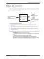
PPPoE (Point-to-Point Protocol over Ethernet)
Note
You cannot see in the display nor in the web interface if a PPPoE connection is active!
Overview
You can establish a PPPoE connection to the BGAN network using the EXPLORER 710 system.
Use PPPoE if you want to control your connection independently of the web interface.
Possible applications are:
•
Connecting a router
•
Connecting broadcast equipment, optionally through a PC
•
Establishing a Picocell for the use of cell phones
The drawing shows connections managed through PPPoE and web interface respectively.
Applications
for PPPoE
Assigning connection
(PDP context) to go out
on the BGAN network
Handling connection
to the BGAN terminal
BGAN
nework
PPPoE
connection
Router
PPPoE
connection
PC and/or broadcast equipment
PDP Context, up to 11
PPPoE
connection
BGAN terminal
Built-in
web
interface
Pico cell
User PC 1 User PC 2
H
IP
d
t
Configuring the connected equipment for PPPoE
How to configure your equipment depends on the type of equipment. Refer to the user
documentation of the equipment. As a minimum, you need to configure the following
parameters in your equipment in order to make PPPoE work with the terminal:
•
98-140012-D
User name and password.
The user name and password can be left blank (or insert user name: void and password:
void). Then the registration on the Access Point is most commonly done in such a way that
the data connection is established with a dynamic IP address from the airtime provider.
To request a static IP (if subscribed to) from the Access Point you must type in the user
name and password from your airtime subscription.
Data connection with computer, smartphone or tablet
34
Chapter 3: To use the EXPLORER 710
Note for MAC OS: User name and password are required. Use user name void and
password void. This works for some ISPs. Contact your airtime provider for further
information.
•
For setups that have a check box for “Enable LCP extensions”, deselect this.
No further configuration is needed to make a Standard IP data connection to the Internet.
See the table below for information on how to configure specific services for your PPPoE
connection.
If you need a certain service, for example a Streaming class, you must type in a specified text
string when asked for a service name. The following table shows the service names supported
by the terminal.
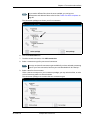
Text to type in the Service
Function
Name field
(Blank)
Initiates a Primary Standard Data connection (default)
XBB:BACKGROUND
Initiates a Primary Standard Data connection (same as blank)
XBB:STREAM32K
Initiates a Primary Streaming 32 kbps connection
XBB:STREAM64K
Initiates a Primary Streaming 64 kbps connection
XBB:STREAM128K
Initiates a Primary Streaming 128 kbps connection
XBB:STREAM176K
Initiates a Primary Streaming 176 kbps connection
XBB:STREAM256K
Initiates a Primary Streaming 256 kbps connection
XBB:X-STREAM
Initiates a Primary X-Stream connection
(from a minimum of 384 kbps up to approximately 450 kbps)
XBB:HDR_STREAM416K
Initiates a Primary Streaming 416 kbps (½HDR) connection
XBB:HDR_STREAM896K
Initiates a Primary Streaming 896 kbps (HDR) connection
XBB:HDR_STREAM416K_64K
Initiates a Primary Streaming 416 kbps (½HDR) upload and
64 kbps download connection
XBB:HDR_STREAM896K_64K
Initiates a Primary Streaming 896 kbps (HDR) upload and
64 kbps download connection
XBB:<AT String>
This allows the PPPoE clients to enter a full AT context
activation string.
Examples:
XBB:AT+CGDCONT=1,ip,”bgan.inmarsat.com”
XBB:AT+CGEQREQ=1,1,64,64,64,64
98-140012-D
Data connection with computer, smartphone or tablet
35
Chapter 3: To use the EXPLORER 710
To access the terminal using AT commands
1. Connect your computer to the EXPLORER 710 terminal.
You may connect directly to the terminal or use a remote connection as described in the
next sections.
2. On the connected computer, start a Telnet session.
3. Select TCP/IP and type in the IP address and port number.
• For local connection, use the local IP address of the EXPLORER 710 (default
192.168.0.1) and port number 5454.
• For remote connection, use the external IP address of the terminal (step 3. in the next
section). The port number for AT commands is normally 5454 but is defined in the
Remote management page under AT commands (see Remote management on
page 82).
4. When the connection is established, type in your AT commands.
To access the terminal from a remote location
To prepare the terminal for remote management
There are three steps you must go through before you can access the terminal from a remote
location:
1. Set up the terminal for control from a remote location as described in Remote
management on page 82.
2. Activate a data connection in one of the following ways:
• Remote start of a data connection with an SMS, see Remote access with SMS on
page 83 and To activate a data connection with an SMS below.
• Automatic activation of a Standard data connection, see step 4. in To set up the
connection mode.
• Manual activation of a data connection, see To start or stop a data connection on
page 32.
3. Note the terminal’s external IP address, found in one of the following ways:
• If you are using SMS activation and you have selected SMS confirmation, you will
receive an SMS with the IP address.
• Otherwise, connect a computer locally to the terminal and start the web interface. The
external IP address of the terminal is shown in the startup page in the tile with the
connection you started in the previous step.
This is the IP address you must use afterwards to access the terminal.
Note
98-140012-D
If Static IP is included in your airtime subscription, we recommend using this static
public IP address for the terminal in order to provide easy access to the terminal. To
use the static IP address, you must set the APN source to SIM default. For details, see
To change the APN for a connection package on page 68.
Data connection with computer, smartphone or tablet
36
Chapter 3: To use the EXPLORER 710
To activate a data connection with an SMS
To be able to activate a data connection on the terminal from a remote location, the terminal
must be set up as described in Remote access with SMS on page 83.
Send an SMS to the mobile number of the terminal. The text in the activation SMS must have
the following format for activating and deactivating a connection:
•
ACTIVATE <name of network user group >:<name of profile> <password>
•
DEACTIVATE <name of network user group>:<name of profile> <password>
• <name of network user group>: default group
• <name of profile> standard (presently, only standard is supported)
• <password> Defined in the web interface under Advanced > Remote management.
Example: To activate a connection for remote management with the standard data
connection and password=1234567890, send an SMS to the terminal with the
text: ACTIVATE default:standard 1234567890
If you have selected SMS confirmation, you receive a response including the IP address to use
when you access the terminal from a remote location (see the next two sections).
Example: A confirmation SMS after sending an activation SMS may look like this:
Activation: Succeeded,. IP 161.30.181.31
Remote access with the web interface
Note
The web interface may take a long time to load the pages if your Internet connection
speed is slow.
After preparing the terminal as described in the previous sections, do as follows to access it:
1. Make sure your remote computer has access to the Internet.
2. On the remote computer, open your web browser.
3. In the address bar of your browser, enter the IP address of the terminal followed by a colon
and the port number
http://<ip address>:<incoming port>.
• <ip address> is the address from step 3. in the previous page
• <incoming port> is the port you defined in Remote management on page 82
Example: If the IP address of the terminal is 161.30.180.12 and the incoming port number
defined in the Remote management page in the web interface is 8080, enter
http://161.30.180.12:8080.
You should now be connected to the built-in web interface of the terminal.
Remote access with AT commands
After preparing the terminal for remote management as described in the previous sections,
access the terminal as described in To access the terminal using AT commands on page 36.
98-140012-D
Data connection with computer, smartphone or tablet
37
Chapter 3: To use the EXPLORER 710
Phone connection
Call types
Definition
The phone connection can be either a Standard voice connection or a 3.1 kHz audio
connection.
•
For outgoing calls, the call type is Standard voice by default.
You can change the call type for your call to 3.1 kHz audio by dialling 2* before the
number.
•
For incoming calls, you can set up in the web interface which call types you want to receive
on the Phone, ISDN or LAN/WLAN interface (IP handset). Only the call types selected for
an interface are received on that interface (by default, all call types are accepted).
When receiving calls, the mobile number determines which call type is used. In your airtime
subscription you have one number for 3.1 kHz audio and one number for Standard voice.
Remember that the call is only received on an interface if the call type used is selected for that
interface.
For information on how to set up the call types in the web interface, see Phone interface
setup on page 56.
To make or receive a phone call with EXPLORER 710
Smartphone, analogue phone, ISDN phone or IP handset
First connect your phone to the relevant interface. For further information, see:
•
Smartphone: To connect your smartphone for making calls on page 21
•
Analogue phone: To connect an analogue phone on page 23
•
ISDN phone: To connect an ISDN phone or modem on page 24
•
IP handset: To connect a wired IP handset for making calls on page 22
To make a call from the EXPLORER 710
•
To make a call, dial
00 <country code> <phone number> followed by # or off-hook key.
Example: To call Cobham SATCOM in Denmark (+45 39558800),
dial 00 45 39558800 #
If there was an error establishing the connection, the web interface and the display of the
EXPLORER 710 show an error message.
98-140012-D
Phone connection
38
Chapter 3: To use the EXPLORER 710
To receive a call
By default, all devices connected to the EXPLORER 710 will ring when one of the mobile
numbers is called. Note however, that this depends on the call type settings. See Call types on
page 38.
Information on missed calls is stored in the call log. You can see the call log in the web
interface (Control panel ? > Logs > Call log).
To make a call to the EXPLORER 710
To make a call to a phone connected to the EXPLORER 710, dial + <Mobile number>
•
+ is the prefix used in front of the country code for international calls. This is 00 when
calling from countries in Europe and from many other countries.
•
Mobile number. The first part of the mobile number is always 870, which is the “country
code” for the BGAN system. For information on the mobile numbers, refer to your airtime
subscription.
Note
98-140012-D
There are two mobile numbers, one for 3.1 kHz audio and one for Standard
voice.
Phone connection
39
Chapter 3: To use the EXPLORER 710
Local numbers and special functions
Overview
There are a number of local numbers and dialing functions available in the EXPLORER 710.
The following list shows the allocated local numbers and special-purpose numbers for the
EXPLORER 710.
Number
Function
00 followed by one of the numbers Short dial phone numbers in phone book.
1-199 and # or off-hook key
0300 followed by # or off-hook key Local call to analog phone.
0400 followed by # or off-hook key Local call broadcast to all ISDN phones.
0 followed by one of the numbers
401-404 and # or off-hook key
Local call to one ISDN phone.
0 followed by one of the numbers
501-516 and # or off-hook key
Local call to one IP handset.
0900 followed by # or off-hook key Local call broadcast to all handsets.
Apart from the numbers above, the EXPLORER 710 uses the following dialing prefixes:
•
1* before the phone number will force the connection to use Standard voice.
•
2* before the phone number will force the connection to use 3.1 kHz audio.
•
#31# before the phone number will hide the callers phone number to the recipient.
•
*31# before the phone number will show the callers phone number to the recipient where
it would otherwise be hidden, e.g. because the number is an ex-directory number.
To make local phone calls
You can make local calls between phones connected to the EXPLORER 710. For an overview of
the available numbers, see the table in the previous section.
To make a local call, dial <local number> followed by # or off-hook key.
To charge your smartphone or tablet
To charge your smartphone or tablet, connect
it to the USB interface next to the power
button on the EXPLORER 710. The connector is
a standard USB A connector.
Note
98-140012-D
There are two levels of charge current, 0.5 A or 2.0 A. Use the web interface to select
the charge current for your device. See USB interface setup.
To charge your smartphone or tablet
40
Chapter 3: To use the EXPLORER 710
To see alerts
When an event requiring the attention of the user occurs, the display shows a warning icon ?.
To see a list of active alerts in the display, do as follows:
1. From the display menu, select Alerts.
2. Select an alert to see details.
All alerts and other events are logged in the Event log
Terminal settings in display
To adjust the display
To adjust the display brightness and timeout, do as follows:
1. From the display menu, select Settings > Display.
2. Select Brightness and select the wanted level with OK.
3. Select Settings > Display > Timeout.
4. Select the period of time the display light should stay on after the last key is pressed.
Automatic power up
The default behaviour of the EXPLORER 710 is to power up automatically when you connect
external power. If you wish, you can change this power up mode, so that the EXPLORER 710 is
only powered if the Power button is pressed. To switch between automatic and manual power
up of the terminal, do as follows:
1. From the display menu, select Settings > Power up mode.
2. Select Auto or Manual.
• Auto: The EXPLORER 710 powers up automatically when external power is applied
• Manual: The EXPLORER 710 powers up only when the power button is pressed
To change the language in the display
The default language of the display is English. You can change the language to French,
German, Russian, Spanish, Chinese or Japanese.
1. From the display menu, select Settings > Language.
2. Select the language you want.
98-140012-D
To see alerts
41
Chapter 3: To use the EXPLORER 710
To see properties of the EXPLORER 710 in the display
Using the display and keypad, you can see properties of the EXPLORER 710. Do as follows:
1. From the display menu, select Properties.
2. Select IP address to see the local IP address of the EXPLORER 710.
3. Select Hardware to see serial numbers and MAC addresses for the EXPLORER 710.
4. Select Software to see the software version of the EXPLORER 710.
5. Select Conformity to see a list of the standards to which the EXPLORER 710 conforms.
6. Select IMEI to see the IMEI number of the EXPLORER 710.
Tracking
The EXPLORER 710 can be used for tracking purposes. You can set up the terminal to report its
position to a server at certain time intervals.
To use the tracking feature you must either set up a tracking server or get a tracking solution
from your service provider. The EXPLORER 710 must be set up to match this server. For
information how to set up the EXPLORER 710, see To set up tracking on page 74. Once set up
on both sides, the EXPLORER 710 will send position reports to the server as specified.
98-140012-D
To see properties of the EXPLORER 710 in the display
42
Chapter 4
To use the web interface
4
This chapter describes how to use the web interface or the Terminal Access part of the
EXPLORER Connect app to operate, set up and configure your system. It has the following
sections:
•
The EXPLORER Connect app
•
The web interface
•
To enter the SIM PIN in the web interface
•
To point the antenna (BGAN)
•
To control data connections from web interface
•
Status information
•
The Control panel
•
To use the logs
•
Battery status information
•
To set up the interfaces
•
To manage IP handsets or smartphones
•
Support features
•
Terminal settings
•
To set up your data connection packages
•
Multiple data connections
•
To set up tracking
•
Advanced settings
98-140012-D
43
Chapter 4: To use the web interface
The EXPLORER Connect app
If you are using a smartphone to configure
your EXPLORER 710, you can use the
EXPLORER Connect app, which is available for
iPhone (from the Apple Store) and for Android
phones (from Google Play).
For an overview of the functions of the
EXPLORER Connect app, see The EXPLORER
Connect app for smartphones on page 9.
To access the configuration settings, start the
EXPLORER Connect app and select
Terminal Access. From this point you have
access to the same settings as from the web
interface.
The web interface
What is the web interface?
The web interface is built into the terminal and is used for operating, setting up and configuring
the system.
You can access the web interface from a computer, tablet or smartphone with a standard
Internet browser.
To access and navigate the web interface
To access the web interface
To access the web interface, do as follows:
1. Start up the terminal.
For details, see To start up the EXPLORER 710 on page 15.
2. Connect your computer to the terminal.
3. Open your browser and enter the IP address of the terminal in the address bar.
The default IP address of the terminal is 192.168.0.1.
Note
98-140012-D
Some parts of the web interface may not be accessible if the user permissions are
limited. For information on how to set up user permissions, see To set up user
permissions on page 77.
The EXPLORER Connect app
44
Chapter 4: To use the web interface
To change the language
When you have access to the web interface, if you want to display a different language than
English, do as follows:
1. Select the Control panel in the top-right corner.
2. Select Terminal settings.
3. At Language, select a language from the drop-down list and click Save.
You can change the language to French, German, Russian, Spanish, Chinese or Japanese.
Overview of the web interface
When the web interface opens, the title bar shows the name of the product. The example
below shows the Terminal settings page.
Name and icon of current page (on opening page: the name of the product)
Icon bar
Status
section
Breadcrumbs
Contents
section
Icon bar
The web interface consists of the following sections.
•
Name of current page. Tap or click to refresh the page.
•
Icon bars at the top and bottom are present on all pages and hold icons that give access
to status such as battery level and signal level as well as active alerts, when relevant. It also
holds the icon for the Control panel. For explanations of the icons, see the next section,
Icons in the icon bars.
•
Breadcrumbs right below the icon bar show the current location in the menu system and
gives access to the higher levels in the menu.
98-140012-D
The web interface
45
Chapter 4: To use the web interface
•
Contents section shows the contents of the selected page. This section is used for
viewing or changing settings, or for performing actions. On the opening page, this section
is used to start and stop data connections.
•
Status section shows the status of the terminal and the network connection, position
information, ongoing calls and data sessions etc. The Status section is not shown on small
screens. If the screen is small (e.g. on a smartphone), you can show/hide the status by
clicking at the bottom of the page.
Icons in the icon bars
The icon bars are always available at the top and bottom of the web interface. Some of the
icons are permanent while others are temporary.
Icon
Explanation
Power status. The icon changes according to status. Click to
see detailed battery status.
Battery level
Battery charging
No battery. Running on external power.
Signal level of the external network.
WLAN interface. Bright when WLAN is enabled, greyed when
it is disabled. Click to access WLAN settings.
Help. Click to get context-sensitive help for the current page.
Control panel. Click to access the settings.
Startup page where you can start and stop data connections.
Click to go to the startup page.
Status. If the screen is not large enough to show the status
field, this icon appears at the bottom of the page. Click the
icon to see status of the terminal and satellite connection.
Click again to go exit the status page.
An alert is active.
Click the icon to see a list of active alerts.
Note that this icon will remain in the icon bar as long as the
alert is still active.
To navigate the web interface
•
98-140012-D
To access status and settings, tap or click the relevant icon in the icon bar or select ?
to access the Control panel. The status or settings are displayed in the contents section.
The web interface
46
Chapter 4: To use the web interface
•
To see your current location and to move back through the Control Panel
menu, use the breadcrumbs just below the icon bar.
•
To scroll through longer pages, use the scroll bar or swipe.
•
To refresh the current page, press Ctrl+F5 (PC) or Apple+R (Apple) or Cmd+R (Apple).
To enter the SIM PIN in the web interface
Do you need a SIM PIN?
Note
You may not have to enter a SIM PIN to access the terminal. This depends on
whether or not the use of a SIM PIN is enabled on your SIM card.
The administrator can enable and disable the use of a SIM PIN. For details, see To
enable or disable the use of a SIM PIN on page 78.
If a smartphone, tablet or computer is connected when you start up the terminal, you can
access the web interface and enter the SIM PIN here.
To enter the SIM PIN
If your SIM card requires a PIN and the PIN has not yet been entered, you must enter it before
you can make calls or access the Internet. Until you have entered the PIN you cannot access
the satellite network, but you can still configure your terminal.
To enter the PIN, do as follows:
1. Access the web interface.
If the terminal needs a PIN, a popup window tells you to enter PIN.
2. Type in your PIN and click OK.
When the correct PIN is entered, the terminal is ready for pointing. When pointing is
completed and the terminal is registered on the network, you are ready to make calls or access
the Internet.
To cancel the SIM PIN
If you select Cancel when you are asked for a PIN, you can use the web interface as normal,
but you will not be able to access the BGAN network to make calls or data sessions. Only
emergency calls will be possible, and only if the network allows it.
To enter the PIN later, after cancelling the first time, do as follows:
1. From the icon bar at the top, click .
The alert list opens.
2. Click Resolve next to Enter PIN for BGAN.
3. Type in your PIN and click OK.
98-140012-D
To enter the SIM PIN in the web interface
47
Chapter 4: To use the web interface
To point the antenna (BGAN)
Before you can use the BGAN network, you must point the antenna in the direction of the
satellite and find the best possible signal strength. For detailed information on the pointing
procedure, see To point the antenna on page 16.
You can use the EXPLORER Connect app or the web interface to help you with the pointing
process.
Pointing in web interface
To start the pointing procedure from the web interface, do as follows:
1. If the pointing process is not automatically started, select (Control panel) and then
Point now.
The signal strength is shown on the screen.
2. Turn and tilt the antenna slowly until you have obtained the highest possible signal
strength.
3. Click OK.
The terminal will now try to register on the BGAN network.
98-140012-D
To point the antenna (BGAN)
48
Chapter 4: To use the web interface
To control data connections from web interface
The startup page of the web interface is used to start and stop data connections and to set up
the data connections.
To start and stop data connections
Note
The icons for starting and stopping connections are only displayed if the
terminal is ready and registered on the BGAN network. Otherwise you cannot start
data connections.
To start and stop data connections on your EXPLORER 710, do as follows:
1. In the opening page, locate the connection package you want to start.
Note
A connection package can consist of one or more connection types or two
bonded EXPLORER 710 channels. For details, see To set up your data connection
packages on page 67.
2. Click to start the connection. If more connections are included in the connection
package, this will start all included connections.
Note
Once a Streaming connection is started, the connection will run until you stop it.
You will be charged for the time you are connected.
3. Click to stop the connection.
If the connection fails, the connection tile shows a red exclamation mark and an error
message. The error message is also shown in the data log, see Data log on page 52.
98-140012-D
To control data connections from web interface
49
Chapter 4: To use the web interface
When a connection is active, the icon turns green and the tile for the active connection shows:
•
IP address: The IP address that has been assigned by the service provider to this session.
•
Transferred data: For Standard data, the tile shows the total amount of transmitted and
received data since the connection was established.
•
Connection duration: For Streaming data, the tile shows the total time the connection has
been active.
•
Bit rate: For Streaming connections, the tile shows the fixed bit rate.
• For the Streaming classes with a guaranteed bit rate, the tile shows the guaranteed bit
rate.
• For the Streaming classes with a dynamic bit rate (BGAN X-Stream and HDR), the tile
shows the currently available bit rate. Note, however, that the bit rate is adjusted
according to the traffic on the connection. It takes approximately 15 seconds for the bit
rate to be updated after traffic has started on the connection.
Default data connection types
By default, the following connections are available:
Name
Type of connection
Standard data
Several users can share the data connection. This type
of connection is ideal for TCP/IP traffic such as e-mail,
file transfer, and Internet/intranet access.
The user pays for the amount of data sent and
received.
Streaming data
The following Streaming classes are
available:
32, 64, 128, 176 or 256 Streaming
BGAN X-Stream
An exclusive, high-priority connection, ensuring
seamless transfer of data. This type of connection is
ideal for time critical applications like live video over
IP.
The user pays for the duration of the connection.
HDR Full Symmetric
HDR Half Symmetric
HDR Full Asymmetric
(64 kbps download, Full HDR upload)
HDR Half Asymmetric
(64 kbps download, Half HDR upload) “Double-channels” available when two EXPLORER 710
2 x HDR Full Symmetric (bonding)
terminals are bonded.
2 x HDR Half Symmetric (bonding)
You can use these connections as they are or build your own connection packages. The
EXPLORER 710 also offers a bonding function, where you can connect two EXPLORER 710
terminals to double the bandwidth. For set up of the connection packages, see the section To
set up your data connection packages on page 67.
98-140012-D
To control data connections from web interface
50
Chapter 4: To use the web interface
Status information
If the window is large enough, it shows a status field at the bottom of the page or in the right
side of the page. If not, click to show the status page. Click again to return to the
previous page.
The Control panel
The Control panel is used for accessing the settings and functions of your EXPLORER 710.
To open the Control panel, click from the bottom right corner of the web interface.
98-140012-D
Status information
51
Chapter 4: To use the web interface
To use the logs
To access the logs
To access the Logs, select and select Logs from the menu. The Logs page contains:
•
Call log: A list of all incoming, outgoing and missed calls since the log was last cleared.
•
Data log: A list of all data sessions since the log was last cleared.
•
Total counters: Totals for each type of service since the log was last cleared.
Date and time is the international UTC time, received from the satellite.
Call log
The Call log shows:
•
Outgoing calls shows the start time, receiving end phone number, duration, type
(Standard voice or 3.1 kHz audio) and, if Call charges have been entered, estimated charge
of each outgoing call.
•
Received calls shows the start time, calling phone number, duration and type (Standard
voice or 3.1 kHz audio) of each incoming call.
•
Missed calls shows the start time, calling phone number and type (Standard voice or
3.1 kHz audio) of each incoming call that was not received.
The Call log also shows the termination cause of each call.
You can clear the Call log under Control Panel > Advanced > Clear logs (requires
Administrator password).
Data log
The Data log shows:
•
Standard data shows data usage (bytes), date and time and estimated charge of each
Standard data session (if Call charges have been entered).
•
Streaming data shows the duration and type (such as 64 kbps, 128 kbps), date and time
and estimated charge of each Streaming data session (if Call charges have been entered).
The Data log also shows the termination cause of each data session.
You can clear the Data log under Control Panel > Advanced > Clear logs (requires
Administrator password).
98-140012-D
To use the logs
52
Chapter 4: To use the web interface
Total counters
The total counters show:
•
Call session totals shows the total duration (hh:mm:ss) for each call type since the log
was last cleared. It also shows the estimated call charge for each call type (if Call charges
have been entered).
•
Data session totals shows totals for each data connection type since the log was last
cleared. For Standard data the totals are shown as amount of data transferred (kB) and for
Streaming connections the totals are shown in duration (hh:mm:ss). It also shows the
estimated charge for each data type (if Call charges have been entered).
You can clear the Total counters under Control Panel > Advanced > Clear total
counters (requires Administrator password).
Battery status information
To view the status of the internal and external (if any) battery, do one of the following:
•
Click the battery symbol from the icon bar at the top of the page, or
•
from the Control panel , select Battery.
The Battery page shows the charging status (Charging or Not charging), the charge level in
percent and the estimated remaining usage time.
Note
The estimated remaining usage time can vary significantly, depending on usage. The
remaining time will be shorter if the terminal is used a heavily (more interfaces in use
and more calls and data sessions active).
For more information on the EXPLORER 710 batteries, see
•
To insert the battery on page 11
•
Normal use of the battery on page 92
•
To recharge batteries on page 92
•
To connect an extra, external EXPLORER 710 battery on page 93
•
Accurate display of the battery capacity on page 93
98-140012-D
Battery status information
53
Chapter 4: To use the web interface
To set up the interfaces
LAN interface setup
The terminal has two LAN connectors. LAN#1 is with PoE (Power over Ethernet).
To configure the LAN interface, do as follows:
1. In the Control panel , click the LAN tile.
2. To enable the LAN interface, select Enable.
Note
•
•
It may take some seconds to enable the interface.
on the LAN tile means the interface is disabled.
on the LAN tile means the interface is enabled.
3. To enable Power over Ethernet (PoE) on LAN#1, select Enable next to Power over
Ethernet.
PoE is used e.g. for powering IP handsets. If you are not using PoE, you can save power by
disabling PoE.
For a description of how to set up the LAN network parameters, see To set up the
connection mode on page 63.
WLAN interface setup
Note
The Internet settings entered in the Terminal settings page also apply for the WLAN
interface. See Internet and LAN connection modes on page 63.
To configure the WLAN interface, do as follows:
1. In the Control panel , click the WLAN tile.
2. To enable the WLAN interface, select Enable.
Note
•
•
It may take some seconds to enable the interface.
on the WLAN tile means the interface is disabled.
on the WLAN tile means the interface is enabled.
3. Next to Region, select the region you are located in.
Note
In some countries, the use of WLAN is not allowed. Before continuing, make sure
WLAN is allowed and licensed in the country where you intend to use it.
4. Select the Channel number used for communication on the WLAN interface.
5. Select Broadcast SSID to show your WLAN access point to other users.
If you clear the box, your WLAN access point is hidden.
98-140012-D
To set up the interfaces
54
Chapter 4: To use the web interface
6. Type in the SSID.
The SSID is a max. 32 character text identifying the wireless local area network. All wireless
devices on a WLAN must use the same SSID in order to communicate with each other. The
default SSID is EXPLORER710.
7. Select the Security standard. You may select one of the following encryption standards:
• None (no encryption is applied)
• WEP-40/64
• WEP-104/128
• WPA-TKIP
• WPA2-AES (selected by default)
8. Next to Key type, select Hexadecimal or Text.
The encryption key must normally be a hexadecimal code. However, if you are using WPATKIP or WPA2-AES encryption (default) you can choose to use a text string, which may be
easier to memorize.
9. Type in the Encryption key for the selected Security standard (not applicable if security
mode = None). The default encryption key is the serial number of the EXPLORER 710.
You can find the serial number under Control panel > Support > About or on the label
on the EXPLORER 710.
10. Click Save.
Port forwarding
Note
Make the port forwarding configuration before starting the data session.
Port forwarding enables you to set up a server connected to the terminal while the terminal is
in Router mode. Without port forwarding it would not be possible to contact the server from
the Internet. We recommend using a static public IP address for the terminal in order to
provide easy access to the terminal. To use the static IP address, it must be included in your
subscription and you must set the APN source to SIM default. For details, see To change the
APN for a connection package on page 68.
The following example shows how to allow Internet access to a mail server (smtp) connected
to the terminal.
The mail server in this example has the IP address 192.168.0.100.
1. From the Control panel , select Port forwarding.
2. Select Forward port to add a new port forwarding.
3. Select Active to activate the port forwarding.
4. Type in the Incoming port start and the Incoming port end.
This is the range of port numbers on the EXPLORER 710 for which incoming traffic to the
EXPLORER 710 will be forwarded.
5. Type in the Destination IP address, which in this example is the IP address of the mail
server: 192.168.0.100.
98-140012-D
To set up the interfaces
55
Chapter 4: To use the web interface
This is the IP address to which the incoming traffic is forwarded.
6. Type in the Destination port start and the Destination port end.
This is the range of port numbers, in this example on the mail server, to which the
incoming traffic will be forwarded.
7. Click Save.
When you have activated a data connection, you can now access the mail server from the
Internet, using the external IP address of the terminal. You can see the external IP address in
the tile with the data connection you have started. For information on how to activate your
data connection, see To start and stop data connections on page 49.
Phone interface setup
To configure the Phone interface, do as follows:
1. In the Control panel , click the Phone tile.
2. To enable the Phone interface, select Enable.
Note
•
•
It may take some seconds to enable the interface.
on the Phone tile means the interface is disabled.
on the Phone tile means the interface is enabled.
3. Set the call type for incoming calls.
You can select Standard voice or 3.1 kHz audio or both.
• If you select both, any device connected to the Phone interface will react (ring) on
incoming calls.
• If you select e.g. Standard voice, the Phone interface will only react on calls made to the
Standard voice phone number.
4. Select the Preferred outgoing call type.
The selected type will be used by default, if possible, for any outgoing call.
5. Click Save.
98-140012-D
To set up the interfaces
56
Chapter 4: To use the web interface
ISDN interface setup
To configure the ISDN interface, do as follows:
1. In the Control panel , click the ISDN tile.
2. Click the ISDN number you want to change settings for.
3. To enable the ISDN interface, select Enable (all ISDN devices).
Note
•
•
It may take some seconds to enable the interface.
on the ISDN tile means the interface is disabled.
on the ISDN tile means the interface is enabled.
4. Set the call type for incoming calls.
You can select Standard voice, 3.1 kHz audio, UDI and/or RDI.
An incoming call to the ISDN interface will only make the connected device ring if the call
type used for the call is selected here.
5. Click Save.
USB interface setup
Note that the USB interface is a Host interface, primarily used for charging devices such as
tablets or smartphones and for recovery software upload.
To configure the USB interface, do as follows:
1. In the Control panel , click the USB tile.
2. To enable the USB interface, select Enable.
Note
•
•
It may take some seconds to enable the interface.
on the USB tile means the interface is disabled.
on the USB tile means the interface is enabled.
3. Select the Charge current.
Select 0.5 A or 2.0 A, depending on the specifications for the device you are going to
connect.
4. Click Save.
98-140012-D
To set up the interfaces
57
Chapter 4: To use the web interface
To manage IP handsets or smartphones
Overview
This section describes how to manage smartphones and IP handsets connected to the
EXPLORER 710.
The terminal supports connection of up to 16 phones through the LAN WLAN interface. Each
phone must have a local number in the range 0501 to 0516 as well as a unique password. For
details, see the next section.
For details on SIP settings and how to connect your phone to the LAN or WLAN interface, see
To connect a phone using LAN or WLAN on page 21.
To manage IP handsets or smartphones in your EXPLORER 710
Do as follows:
1. Connect your smartphone to the WLAN interface of the terminal or your IP handset to the
LAN#1 interface . For details, see To connect a phone using LAN or WLAN on page 21.
2. In the web interface, select (Control panel) > IP handsets.
3. Click the tile for the handset number you want to manage.
4. Select Enable to enable the handset.
Note
•
•
It may take some seconds to enable the handset.
on the tile for your handset means the handset is disabled.
on the tile for your handset means the handset is enabled.
5. To change the Password, simply type in the new number.
6. Set the call type for incoming calls.
You can select Standard voice or 3.1 kHz audio or both.
• If you select both, the handset will react (ring) on incoming calls.
• If you select e.g. Standard voice, the handset will only react on calls made to the
Standard voice phone number.
7. Select the Preferred outgoing call type.
The selected type will be used by default, if possible, for any outgoing call from this
handset.
8. Click Save.
9. In the smartphone or IP handset, enter the local number and the password you just
entered in the EXPLORER 710. See the documentation for your handset for details.
Note
The user name is also the local number for the handset.
The handset remains in the list after disconnecting. When the handset is connected again, it is
automatically recognized and ready for use, if enabled.
98-140012-D
To manage IP handsets or smartphones
58
Chapter 4: To use the web interface
Support features
To open the Support page, select (Control panel) > Support.
To view the Alerts
When an alert is registered, the web interface shows a warning icon in the icon bar as long
as the alert is active. The Alerts list only shows alerts that are currently active.
To view the alerts, click from the icon bar at the top of the web interface, or select Alerts
from the Support page.
To view the Event log
The Event log shows events that occurred in the past and are no longer active. It includes
events of informational character describing normal phases of operation for the terminal, and
also alerts that have appeared in the Alerts list.
To view the event log, select Event log from the Support page.
To create a diagnostics report
The diagnostic report contains relevant information for troubleshooting. When contacting
your supplier for support, please enclose this file. To generate a diagnostic report, do as follows:
1. From the Support page, click Diagnostics report.
2. Click Generate report.
Note
It may take a few minutes to generate the report.
3. Select Download report.
4. Choose a location for the file and save it.
98-140012-D
Support features
59
Chapter 4: To use the web interface
To update software
Important
If the battery power is 25% or less you must connect DC power to the terminal
before starting the software update. Once connected, do not remove DC power
until the software update is completed.
To update the software in the EXPLORER 710, do as follows:
1. Download the new software or acquire the software from Cobham SATCOM and save it on
your computer.
2. Open the web interface and enter the Control panel .
3. Click Support > Update software.
4. Click Update software...
5. Browse to the new software version and click Open. The software file has the extension
“.tiif”.
Note
The update procedure takes some minutes to complete. During the software
update, the Status LED is flashing blue.
6. The terminal reboots and you should now get a message that the software installation was
successful.
7. Click OK.
8. Press Ctrl+F5 to make sure the information in the web interface is updated.
You can check the software version under Control panel > Support > About.
If, for some reason, you cannot upload software using the web interface, you can also use the
USB interface. For details, see To update software with USB on page 90.
To view extended status
To see the Extended status page, select Support > Extended status.
To view updated information on the Extended status page, click the icon in the top left
corner to refresh the page.
The Extended Status page shows information such as IAI-2 status, IMSI number and IMEI
number.
98-140012-D
Support features
60
Chapter 4: To use the web interface
To reset the administrator password
If you have forgotten the administrator password, do as follows:
1. Contact your supplier for a reset code.
Report the serial number and IMEI number of the terminal.
You can find the serial number and IMEI number in the display on the terminal by selecting
the menu and then Properties.
2. After receiving the reset code from your supplier, select Reset password from the
Support page.
3. Type in the reset code obtained from your supplier and click Reset.
4. The password is disabled.
You now have access to all settings. If you want to use a password, enable the password as
described in To enable the administrator password on page 76.
About
The About page shows the Serial number and software version of your EXPLORER 710
and legal information. It also shows your Help desk information, if it has been entered under
Advanced > Help desk.
To access the About page, select Support > About.
98-140012-D
Support features
61
Chapter 4: To use the web interface
Terminal settings
To configure the terminal settings, select (Control panel) > Terminal settings.
98-140012-D
Terminal settings
62
Chapter 4: To use the web interface
Power-up mode with external power
You can set the terminal to automatically power up when external power is applied.
1. In the Terminal settings page, locate Power-up mode when using external power.
2. Select Automatic or Manual.
• Automatic means the terminal powers up automatically when external power is applied.
• Manual means you must use the power switch to power the terminal.
3. Click Save.
Pointing at start-up
1. In the Terminal settings page, locate Pointing mode at start-up.
2. Select Automatic or Manual.
• If the EXPLORER 710 is moved around between each power up, select Manual from the
drop-down list. With this setting, the terminal will go through the pointing procedure
every time the terminal is powered.
• If the EXPLORER 710 antenna is placed in a fixed position and the signal strength is
sufficient, select Automatic to make the EXPLORER 710 automatically register on the
satellite network when the terminal is powered.
3. Click Save.
To set up the connection mode
Internet and LAN connection modes
In the web interface you can set up the Internet connection mode and the IP addressing
between the EXPLORER 710 and devices connected to the EXPLORER 710. The EXPLORER 710
has a built-in DHCP server which can be used to dynamically assign IP addresses to devices
connected to the EXPLORER 710.
The drawing in the next page shows examples of the IP addressing in router mode (default
setup) and modem mode.
98-140012-D
Terminal settings
63
Chapter 4: To use the web interface
5RXWHUPRGH
'HIDXOWVHWXSH[DPSOH
7HUPLQDO
'HYLFH
'HYLFH
Q
DVVLJQHGE\WKH
WHUPLQDOYLD'+&3
P
DVVLJQHGE\WKH
WHUPLQDOYLD'+&3
'+&3
1$7
%*$1QHWZRUN
'+&3VHUYHU
DVVLJQHGE\WKH%*$1
QHWZRUNYLD'+&3
Q
0RGHPPRGHQRFRQQHFWLRQWRWKH%*$1QHWZRUN
([DPSOH
7HUPLQDO
'+&3
%*$1QHWZRUN
'HYLFH
'+&3VHUYHU
Q
DVVLJQHGE\WKH
WHUPLQDOYLD'+&3
/RFDO,3DGGUHVV
Q
0RGHPPRGHZLWKDFWLYHFRQQHFWLRQWRWKH%*$1QHWZRUN
([DPSOH
,3DGGUHVVWRDFFHVVWKHWHUPLQDO¶VZHE
LQWHUIDFH
DVVLJQHGE\WKH%*$1QHWZRUNYLD'+&3
7HUPLQDO
'HYLFH
%*$1QHWZRUN
'+&3VHUYHU
Q
DVVLJQHGE\WKH%*$1
QHWZRUNYLD'+&3
To set up the connection mode of the EXPLORER 710, do as follows:
1. From the Terminal settings page, locate Connection.
2. At Internet connection mode, select Modem mode or Router mode. Router mode
is the default setting and is recommended for most purposes.
• Select Router mode if one or more computers are connected and the EXPLORER 710
should act as a router. When Router mode is selected, the EXPLORER 710 uses the builtin NAT module for making the necessary address translations.
• Select Modem mode if only one computer is connected, and the EXPLORER 710
should act as a modem, or more than one computer is connected using an external
router. 1
Note
Do not connect more than one computer in Modem mode, unless you have an
external router.
1. Note that in modem mode the local IP address is assigned by the external network (see drawing
in the beginning of this section), so when the terminal is connected to the external network you
cannot access the web interface with the usual local IP address. When the external network
is disconnected, the local IP address falls back to the address mentioned in step 3. (next step).
98-140012-D
Terminal settings
64
Chapter 4: To use the web interface
3. Under Local IP address, type in a new IP address if you want to change the Local IP
address of the terminal. This is the address used to access the web interface. The default IP
address is 192.168.0.1.
Note
If the EXPLORER 710 is in modem mode and connected to the BGAN network
(see previous step), you cannot use this address to access the web
interface, because the network dynamically assigns the IP address for the
EXPLORER 710.
So to access the web interface in modem mode, you must do one of the
following:
•
Access the web interface when there is no data connection on the BGAN
network
•
Check the IP address of your connected equipment and add 1 to the last
number. This is the IP address to access the web interface. (See the drawing
in the previous page).
4. To enable automatic activation of your data connection, select Automatic activation.
• When you select automatic activation and connect to the LAN or WLAN interface, the
data connection is automatically established as soon as the EXPLORER 710 and its BGAN
connection are ready.
Note
You are charged for the data transferred. You may want to disable automatic
updates in your LAN or WLAN device to avoid unnecessary charges.
• When you disable automatic activation (default), you can control the data connection
manually from the startup page .
5. Under DHCP, select DHCP Enabled (recommended for most purposes).
• If you select DHCP Enabled, the terminal assigns dynamic IP addresses to devices
connected to the terminal.
• If disable DHCP, you need to set up a static IP address in the connected device.
6. If you want to change the Network mask for the local network of the terminal, type in
the new network mask. The default network mask is 255.255.255.0.
7. Under DHCP range start and DHCP range end, type in the range of IP addresses that
should be assigned to locally connected equipment.
8. Click Save.
98-140012-D
Terminal settings
65
Chapter 4: To use the web interface
To set up channel bonding
You can connect two EXPLORER 710 terminals to obtain a higher bandwidth. First set up each
of the two terminals as described below.
Note
A bonding server must first be set up, in order receive and “reassemble” the two
signals into one at the receiving end. You must know the server name, user name and
password in order to set up the EXPLORER 710 terminals used for bonding.
You find the Bonding server application in the Cobham SATCOM Self Service Center
at http://esupport.thrane.com/?group=SSC.
1. In the Terminal settings page, locate the Channel bonding section.
2. Select Enable to enable channel bonding.
3. At Bonding server, enter the name of the server used for the bonding function. You can
type either the name or the IP address of the server.
4. Enter the user name and password for the server.
5. Click Save.
6. Connect and start up the two EXPLORER 710 terminals as described in Bonding of
terminals on page 32.
To enable or disable the pointing sound
The EXPLORER 710 can make a sound to guide you through the pointing procedure (default
enabled). To enable or disable the pointing sound, do as follows:
1. In the Terminal settings page, locate the Audio indication section.
2. Select Audio assisted pointing if you want to use a pointing sound to assist your
pointing process.
3. Click Save.
98-140012-D
Terminal settings
66
Chapter 4: To use the web interface
To select the GNSS type
To select which navigation system to use with your EXPLORER 710, do as follows:
1. In the Terminal settings page, locate the GNSS section.
2. Select GPS or GLONASS.
3. Click Save.
Note
It may take some minutes for the EXPLORER 710 to change the navigation system.
To select the language
The default language of the web interface is English. You can change the language to French,
German, Russian, Spanish, Chinese or Japanese.
To change the language, do as follows:
1. In the Terminal settings page, locate the Language section.
2. Select a language from the list and click Save.
To set up your data connection packages
Connection packages
If you want to be able to
Do as follows
Run one connection at a time
from the startup page.
This is the default setup, with only one connection in each
connection package.
Start the connection you need from the web interface or
the display.
Use different connection types Add more connections to a connection package and apply
for different types of traffic.
filters to assign different connection types to different
types of traffic. See To create a package with multiple
connections below.
Start all the connections in the package by starting the
package from the web interface or the display.
Extend your bandwidth by
connecting two EXPLORER 710
terminals (bonding).
Set up two EXPLORER 710 terminals as described in To set
up channel bonding on page 66 and Bonding of terminals
on page 32.
Start the bonding connection package from the web
interface or the display (typically named 2 * <connection
type>).
98-140012-D
To set up your data connection packages
67
Chapter 4: To use the web interface
To change the contents of a connection package
To change the contents of a connection package, click in the right side of the tile with the
connection package that you want to change.
If you want to
Do as follows
Change the name of the connection
package
Click Properties, type in the new name and click
Save. The new name is shown on the tile on the
startup page.
Delete a connection package
Click Delete packagea
Note: You cannot delete Standard data.
Remove connections from the
connection package
Click in the tile with the connection you want
to remove.
Add a connection to the package
See Multiple data connections on page 69.
a. If you accidentally delete a connection package, you can either create a new manually, or restore factory
settings. Note, however, that all changes to the configuration will be lost if you restore factory settings.
To change the APN for a connection package
By default a connection package is set to use no IP Header compression and to use the APN
(Access Point Name) from the SIM card. This is suitable for most applications.
Note
It is recommended to leave IP Header compression disabled. This means that the
data packets are transmitted more reliably with less data loss. However, you can select
IP Header compression with the risk of less stability.
If you want to use a different APN, do as follows:
1. Click in the right side of the tile with the connection package that you want to change.
2. Select Parameters.
3. Next to APN, select the source of the APN.
• SIM default (default and recommended setting): The APN is taken from the SIM card.
• Network assigned: The APN is assigned from the network.
• User defined: APNs are provided from the Airtime Provider. Type in the APN next to
User defined name.
4. If your APN uses a password, type in the User name and Password provided from the
Airtime Provider.
5. Click Save.
98-140012-D
To set up your data connection packages
68
Chapter 4: To use the web interface
Multiple data connections
If you want to have different types of connections running at the same time, you can build
connection packages with the connections you want, using filters to determine which traffic
should use which connection type.
&RQQHFWLRQSDFNDJH
7UDIILFIORZ
ILOWHUV
7\SHRIWUDIILFHJ8'37&3
7\SHRI6HUYLFH4XDOLW\RI6HUYLFH
,3DGGUHVV
3RUWQXPEHUV
,3VHFXULW\XVHG,36HF63,
8'3ILOWHU
1RILOWHU
&RQQHFWLRQW\SH
6WUHDPLQJ
&RQQHFWLRQW\SH
6WDQGDUG
6WUHDPLQJ
FRQQHFWLRQ
6WDQGDUG,3
FRQQHFWLRQ
(JYLGHR
VWUHDPLQJ
(JHPDLODQG
ZHEEURZVLQJ
You then have to set up the following:
•
Create a new package. See the next section To create a package with multiple
connections.
•
Add connections to the package.and select a predefined filter for each connection.
•
Optional: Change the APN for the package. See To change the APN for a connection
package on page 68.
Example: You want to be able to send email while making a live video transmission with your
EXPLORER 710:
You build a new package containing 2 connections:
1: A 256 kbps streaming connection (for your video transmission). Select the UDP
filter.
2: A Standard connection (for email etc.). Select “No filter”.
When you have started this connection package, your video input to the
EXPLORER 710 terminal is now automatically routed to the 256 kbps streaming
connection. All other traffic is routed to the Standard data connection.
98-140012-D
Multiple data connections
69
Chapter 4: To use the web interface
To create a package with multiple connections
1. From the startup page, click New connection package.
2. Type a name for the new connection package and click Save.
3. Click Click here to create connections.
4. To add a connection to the connection package, click Add connection and select the
type of connection you want to add.
Important
98-140012-D
The filters are applied in the order they are added. This means that if you
want to have a connection with no filter, it must be the last connection you
add to your connection package. If not, the next filters are ignored, because
“No filter” means all data passes through without filtering.
Multiple data connections
70
Chapter 4: To use the web interface
5. Select a predefined filter for your new connection.
The predefined filters are:
• UDP: Filters traffic using UDP protocol (such as video streaming or Voice over IP).
• TCP: Filters Traffic using TCP protocol (such as web browsing)
• No filter: All data pass through. Use only for the last connection you add to your
package.
The filters are applied in the order in which they were defined. This means that if you have
a connection with no filter as the last connection, all traffic that does not match the first
filters in the list will be passed through on this last connection. For this reason we
recommend a Standard data connection for the “No filter” connection.
98-140012-D
Multiple data connections
71
Chapter 4: To use the web interface
Note
If you need a different filter than the ones available, you can log in as
administrator and add new filters to the list. See Traffic flow filter templates on
page 86.
The connection package now shows your first connection.
6. Click the Connections tile.
7. To add a second connection, click Add connection.
8. Select a connection type for your second connection.
Note
You may not have all connection types available if you have selected a streaming
type for your first connection, because your total bandwidth will be “filled up”.
9. Select a filter for the connection.
If this is the last connection in your connection package, you may select No filter, in order
to let all remaining traffic use this connection
The connection package now contains the two connection types.
98-140012-D
Multiple data connections
72
Chapter 4: To use the web interface
10. Click Save package.
The New connection package is now on the startup page.
When traffic is detected on the LAN or WLAN interface, the filters are used to route the traffic.
E.g. if you connect your video equipment with UDP traffic to the EXPLORER 710, your video
transmission will use the connection that has UDP in the filter settings (128 Streaming in the
example above).
98-140012-D
Multiple data connections
73
Chapter 4: To use the web interface
To set up tracking
You can set up the EXPLORER 710 to report to a server at certain time intervals. To set up
tracking, do as follows:
1. From the Control panel , select Tracking.
2. To enable tracking of the EXPLORER 710, select Enable tracking.
3. At Tracking and HDR, select Share HDR connection or Disable HDR connection.
When tracking is enabled, you cannot use a full HDR or BGAN X-Stream connection, so you
must select one of these two options:
• Share HDR connection: When Tracking is enabled and a HDR connection is started,
the terminal will use part of the HDR bandwidth for tracking.
• Disable HDR connection: As long as Tracking is enabled, you cannot start a HDR
connection.
4. Select the Report type.
98-140012-D
To set up tracking
74
Chapter 4: To use the web interface
• Compressed. Only latitude and longitude are reported.
• Extended. Apart from latitude and longitude, heading and altitude are also included.
• ECEF. The same information as Extended, but position and speed data are 3D (ECEF
coordinates).
5. Under Server connection, type in the following details:
• Host: The IP address of the server that the EXPLORER 710 will report to.
• Server port: Port number on the server. Default number is 7474.
• Client port: Port number on the EXPLORER 710. Default number is 7475.
• Encryption key: A supplied 128 bit key which must match on both the client and
server side.
6. Under APN, select the source of the APN.
• SIM default (recommended): The APN is taken from the SIM card.
• Network assigned: The APN is assigned from the network.
• User defined: APNs are provided from the Airtime Provider. Type in the APN next to
User defined name.
7. Type in the Report interval in hours (h) and minutes (m).
Example: If you type in 1 h 30 m, the EXPLORER 710 will send a report for every 1½
hour.
8. Click Save.
If you have disabled HDR in step 3., you can see the status of the tracking link in the status area
of the web interface. If the status area is not shown, click to see it.
Note
98-140012-D
You can set up whether or not you want to allow the tracking server to control these
settings. See Remote control of tracking on page 84.
To set up tracking
75
Chapter 4: To use the web interface
Advanced settings
First time use
The first time you access the EXPLORER 710 web interface the administrator password is
disabled, so you have access to all settings. If you want to use an administrator password, you
can enable it as described in the next section.
Administrator password
To enable the administrator password
If the administrator password is disabled and you want to protect the advanced settings with a
password, do as follows:
1. From the Control panel , select Advanced.
2. Select Enable admin password.
3. Type in the administrator password you want to use.
4. Repeat the new password on the next line.
5. Click Save.
To disable the administrator password
If you want to disable the administrator password, do as follows:
1. From the Control panel , select Advanced.
2. If you are not already logged in, enter the administrator password and click Login.
3. Select Disable admin password.
All settings are now available without password protection.
To log in
If the administrator password is enabled, the Advanced settings require an administrator
password. To log in as administrator, do as follows:
1. From the Control panel , select Advanced.
If you are not logged in as administrator you are now prompted to log in.
2. Enter the Administrator password.
If you have forgotten the administrator password, you can reset the password. For details,
see To reset the administrator password on page 61. The old user name and password will
apply until you have finished the reset procedure.
3. Click Login.
98-140012-D
Advanced settings
76
Chapter 4: To use the web interface
To change the administrator password
To change the administrator password, do as follows:
1. Log in as administrator
2. Under Advanced, select Change admin password.
3. Type in the Old password.
4. Type in the New password and retype it on the next line.
5. Click Save.
At the next login the new password is required.
To log out as administrator
If you have not entered anything for 30 minutes under Advanced, you are logged out
automatically. To log out manually, click Logout admin in the Advanced page.
To set up user permissions
You can allow or deny users access to certain functions and make these pages read-only. This is
useful if you want to protect the system against unintended changes. Study this screen
thoroughly and decide to which areas of the system you want to give non-administrator users
access. To set up the user permissions, do as follows:
1. Under Advanced, select User permissions.
2. Under Allow users to:, select the settings you want to allow users to access.
3. Under Allow AT commands on:, select LAN/WLAN interface if you want to allow the
use of AT commands.
AT commands are low-level commands used to control modems, in this case the
EXPLORER 710. They are typically used during service and maintenance or when
troubleshooting the terminal.
4. Under Allow user accounts:, select Service user account if you want to enable the
use of a service user account.
5. Click Save.
The settings without a check mark can only be viewed but not changed by the nonadministrator user.
98-140012-D
Advanced settings
77
Chapter 4: To use the web interface
To restore factory settings
To restore the factory settings of the EXPLORER 710, do as follows:
1. Under Advanced, select Factory reset.
Important
All configuration will be lost and the EXPLORER 710 will return to the default
configuration.
2. Click OK.
The terminal will now reboot and start up with the factory settings.
To enable or disable the use of a SIM PIN
To enable or disable the use of a PIN to access the terminal, do as follows:
1. Under Advanced, select Enable/disable SIM PIN.
2. Under Enable/Disable PIN select or clear the box next to Require PIN on startup.
• If you clear the box, you can access and use the terminal without entering a PIN
• If you select the box, you must enter a PIN on startup before you can make calls or data
sessions
3. If you selected Require PIN on startup, type in the PIN next to Current PIN.
4. Click Save.
The new PIN settings will take effect at next power on.
To change the SIM PIN
To change the PIN used to access the BGAN network, do as follows:
1. Under Advanced, select Change SIM PIN.
2. Under Change SIM PIN type in the Current PIN.
3. Type in the New PIN and retype it on the next line.
4. Click Save. The new PIN settings will take effect at next power on.
98-140012-D
Advanced settings
78
Chapter 4: To use the web interface
SIM lock
The SIM lock feature can be used by suppliers to lock your SIM card to a specific provider or
distribution partner. For further information, contact your supplier.
To save or load a configuration
If you need to reuse a configuration in another terminal of the same type and software
version, you can save your current configuration to a file, which can then be loaded into the
other terminal.
Note
Configuration files can only be exchanged between terminals with the same software
version!
To save a configuration to a file
To save the current configuration of your EXPLORER 710 to a file on your computer, do as
follows:
5. In the Advanced page, click Load/save configuration.
6. Click Save configuration.
The configuration file is saved in the EXPLORER 710.
7. Click Download configuration...
The configuration is downloaded from the EXPLORER 710 to the downloads section of
your computer.
To load a configuration from a file
To load a configuration from a file into your EXPLORER 710, do as follows:
1. In the Advanced page, click Load/save configuration.
2. Click Load configuration.
3. Browse to the configuration file and click Open...
The configuration is now loaded into your EXPLORER 710. When the configuration is loaded
successfully, the EXPLORER 710 reboots and starts up with the new configuration.
98-140012-D
Advanced settings
79
Chapter 4: To use the web interface
Link monitoring
You can monitor the external IP connection of the EXPLORER 710 system using the link
monitoring feature. With this feature activated, the terminal will send out ping commands
(ICMP Echo Requests) to a server of your choice.
Note
The data connection must be activated before link monitoring can start. See To start
and stop data connections on page 49.
To set up link monitoring, do as follows:
1. Under Advanced, select Link monitoring.
2. Select Enable Link monitoring.
3. At Ping interval (minutes) select the Interval in minutes between the ping commands.
4. Select the Number of retries before the terminal reboots.
5. Type in the Primary and optionally the Secondary IP address.
This is the IP address of the server(s) to which the terminal will send ping commands.
Note
Use a server that is reliable and that responds to ICMP Echo Requests.
6. Click Save.
When a data session is started, the terminal will start sending ping commands to the Primary IP
address the number of times specified at Number of retries. If no response is received, it will
send the same number of ping commands to the Secondary IP address, if available. If no
response is received here, the terminal will reboot.
Data limits
You can set a limit for the use of data services with the EXPLORER 710 system.
Once the entered limit is reached, the connection is automatically stopped. This is recorded in
the data log. To continue using the data service you must start a new connection by clicking on
the desired connection on the startup page.
Note
If you have enabled automatic activation of the Standard data connection and you
set a data limit for the Standard data connection, automatic activation is disabled.
To set data limits, do as follows:
1. Under Advanced, select Data limits.
2. Select the type of connection you want to limit.
3. Type in the amount of data or time allowed and select the appropriate units.
4. Select Enable.
5. Click Save to save the settings.
98-140012-D
Advanced settings
80
Chapter 4: To use the web interface
Call charges
Note
Cobham SATCOM does not take responsibility for the correctness of the estimated
charges. This calculation is only a rough estimate of the charge, based on the tariff
entered by the user. Also, the Airtime Provider may have different methods of
measuring the airtime used.
If you know the tariff for your subscribed services, you can enter these tariffs in the web
interface and automatically calculate the estimated charges for your calls and data sessions. To
enter the call tariffs, do as follows:
1. Under Advanced, select Call Charges.
2. Select the currency from the Displayed currency drop-down list.
3. Enter the tariff for each of the services.
4. Click Save.
The entered tariffs are used for estimating the charges for calls and data sessions. For
further information, see Call log on page 52.
To clear the logs
To clear the logs of the terminal, do as follows:
1. Under Advanced, click Clear logs.
2. Click OK.
This will clear the call log and the data log.
To reset the total counters
To reset the counters for the time connected, do as follows:
1. Under Advanced, click Reset total counters.
2. Click OK.This will reset the counters under Control panel > Logs > Total counters.
98-140012-D
Advanced settings
81
Chapter 4: To use the web interface
Remote management
You can set up the terminal so that it can be controlled from a remote location.
To set up the terminal for remote management, select Advanced > Remote management
from the Control panel.
98-140012-D
Advanced settings
82
Chapter 4: To use the web interface
Remote access with IP
1. From the Remote management page, select Enable access to web server and/or
Enable access to AT commands.
2. Type in the Incoming port numbers to use for the web server and for AT commands.
The default port numbers are:
• web server: 80
• AT commands: 5454
Note
The port number must be available at your service provider.
3. Under Trusted IP addresses, click Add IP address and type in the IP address of the
device you want to give access to the terminal.
4. To add more IP addresses, click Add IP address again.
Note
To be able to access the terminal you must have an active data connection.
After preparing the terminal and activating the connection you can access the terminal from
one of the trusted IP addresses, using the incoming port defined in the Incoming port field.
• For information on how to prepare the terminal for remote activation of a data
connection, see the next section Remote access with SMS.
• For information on how to access the terminal, see To access the terminal from a
remote location on page 36.
If Static IP is included in your airtime subscription, we recommend using this static public IP
address for the terminal in order to provide easy access to the terminal. To use the static IP
address, it must be included in your airtime subscription and you must set the APN source to
SIM default. For details, see To change the APN for a connection package on page 68.
Remote access with SMS
Note
The terminal must be logged on to the satellite services to receive and accept an SMS.
If the SMS is considered too old or sent before the terminal has been switched on and
has logged on, the SMS will be ignored.
1. From the Remote management page, select whether you want to Enable remote
activation of data sessions.
2. Select whether you want an SMS confirmation for your data activation SMS.
Important
If you want to receive an SMS with the IP address of the terminal after
sending an activation SMS, you must select Send SMS confirmation.
3. Select Enable access to AT commands, if you want to enable the EXPLORER 710 to
receive AT commands via SMS for remote management.
98-140012-D
Advanced settings
83
Chapter 4: To use the web interface
4. Enter the password. It can be up to 32 characters long. The characters 0-9, a-z and A-Z are
allowed. The password is mandatory and must match the password in the SMS. See To
activate a data connection with an SMS on page 37.
5. Enter at least one trusted mobile number from which the terminal accepts an SMS. If no
numbers are entered the feature is disabled automatically. Use the wild card * to accept a
range of trusted numbers. Leave out the prefix before the country code (example: for
“+45” write only “45”)
Mobile number with wild card
Mobile numbers accepted
+453955880*
4539558800 to 4539558809
+45395588*
4539558800 to 4539558899
6. To add more phone numbers, click Add phone number again.
7. Click Save.
For information on how to send an activation SMS, see To activate a data connection with an
SMS on page 37.
Remote control of tracking
When you are using the tracking function of the EXPLORER 710, you can set up the terminal so
that the tracking server can access the EXPLORER 710 e.g. to start or stop tracking or to change
reporting intervals.
To allow the tracking server to control the tracking settings, do as follows:
1. Under Advanced, select Tracking settings.
2. Select Allow remote control of tracking.
3. Click Save.
The EXPLORER terminal will now accept commands from the specified tracking server, for
example to change reporting intervals or start/stop reporting.
To configure data connection types and filters
If the default connection types and filters do not meet your requirements, you can build new
templates for the connection types and/or traffic flow filters to match your needs.
Connection templates
To access the connection templates, do as follows:
1. Under Advanced, select Templates.
2. Select Connections.
3. To delete a connection type, click in the right side of the connection type.
98-140012-D
Advanced settings
84
Chapter 4: To use the web interface
4. To add a new connection type, click Add template and proceed with the next steps.
5. Select an existing Connection template as a basis for your new template.
6. Type in a suitable Name for the connection type.
7. Select the Traffic class.
• Standard is a shared, best-effort connection, used e.g. for email or Internet browsing.
• Streaming is an exclusive, high-priority connection with a guaranteed bit rate.
8. Select the following bit rates:
• Max. bit rate upload is the maximum upload bit rate allowed for this connection type.
• Max. bit rate download is the maximum download bit rate allowed for this
connection type.
• Guaranteed bit rate upload is the guaranteed upload bit rate needed for this
connection type.
• Guaranteed bit rate download is the guaranteed download bit rate needed for this
connection type.
9. In the Transfer delay field, type in the delay in ms. This is the delay from the time data is
received in the terminal until it arrives at the receiving end. You can enter one of the
following values:
• 500 ms (error correction is disabled)
• 4000 ms (error correction is applied)
• 0 ms (error correction determined by network)
10. Click Save.
The new template will now be available for selection when you build your connection
packages.
98-140012-D
Advanced settings
85
Chapter 4: To use the web interface
Traffic flow filter templates
The traffic flow filters are used to filter the data traffic, so you can use different connection
types for different types of traffic. There are two predefined filters, UDP and TCP.
•
UDP is used for traffic using UDP protocol (such as video streaming or Voice over IP)
•
TCP is used for traffic using TCP protocol (such as web browsing).
You can also select No filter. This option is only suitable for the last connection you add to a
connection package, because the filters are applied in the order they are added to the
connection package. See Multiple data connections on page 69.
If the predefined filters do not meet your requirements, you can create additional filter
templates. Do as follows:
1. Under Advanced, select Templates.
2. Select Traffic flow filters.
3. To delete a traffic flow filter, click in the right side of the filter tile.
4. To add a new traffic flow filter, click Add template and proceed with the next steps.
98-140012-D
Advanced settings
86
Chapter 4: To use the web interface
5. Type in a suitable name for the filter.
6. Select the item(s) you want to use for filtering and enter the details for the item(s). You can
select one or more of the following items:
• Use global IP filter.
Traffic to and from the IP address or network (subnet mask) entered here is
automatically routed to the connection type associated with this traffic flow filter.
• Use protocol number filter.
This is the type of protocol that is used for the data traffic. E.g. if this is set to 17 (UDP),
the filter will automatically route UDP data traffic to the connection type associated
with this traffic flow filter.
98-140012-D
Advanced settings
87
Chapter 4: To use the web interface
• Use local port filter.
This is a range of local port numbers on the terminal. The filter will route traffic to and
from any of these port numbers to the connection type associated with this traffic flow
filter.
• Use global port filter.
This is a range of global port numbers on the terminal. The filter will route traffic to and
from any of these port numbers to the connection type associated with this traffic flow
filter.
• Use type of service filter.
Type of Service (TOS) is used to define the Quality of Service. Set this value to a number
between 0 and 255.The filter will route traffic with this Quality of Service to the
connection type associated with this traffic flow filter.
• Use IPsec SPI filter.
IP security. The filter will route traffic using the Security Parameter Index (SPI) stated
here to the connection type associated with this traffic flow filter.
7. Click Save.
The new filter will now be available for selection when you add new connections to a
connection package.
Example: You want a connection package, which allows you to use uninterrupted Voice over
IP while having a Standard data connection for web browsing etc.
1. Create a filter template with
• Protocol=UDP (Use protocol number filter)
• Type of Service = 0xb8 and Type of Service mask = 255 (Use type of service filter)
The UDP protocol is suitable for UDP voice streaming and the TOS value 0xb8 is used by
some linksys Voice over IP adapters.
2. Create a connection package as described in Multiple data connections on page 69.
3. Add a Standard connection with No filter.
4. Add an additional connection, e.g. 32 kbps Streaming with the new filter you created in
step 1.
Help desk
Under Help desk you can enter the contact information you want for your EXPLORER 710. The
Help desk contact information is empty by default. You must provide the contact information,
e.g. the phone number for your Airtime Provider. Do as follows:
1. In the Advanced page, select Help desk.
2. Type in the contact information you want.
3. select Save.
4. The Help desk information is now available from the About page ( (Control panel) >
Support > About).
98-140012-D
Advanced settings
88
Chapter 5
Maintenance and troubleshooting
5
To get support
Contact information
Should your Cobham SATCOM product fail, please contact your dealer or installer, or the
nearest Cobham SATCOM partner. You will find the partner details on
www.cobham.com/satcom where you also find the Cobham SATCOM Self Service Center webportal, which may help you solve the problem.
Your dealer, installer or Cobham SATCOM partner will assist you whether the need is user
training, technical support, arranging on-site repair or sending the product for repair.
Your dealer, installer or Cobham SATCOM partner will also take care of any warranty issue.
To repack for shipment
Should you need to send the product for repair, please read the below information before
packing the product.
The shipping carton has been carefully designed to protect the EXPLORER 710 and its
accessories during shipment. This carton and its associated packing material should be used
when repacking for shipment. Attach a tag indicating the type of service required, return
address, part number and full serial number. Mark the carton FRAGILE to ensure careful
handling.
Note
Correct shipment is the customer’s own responsibility.
If the original shipping carton is not available, the following general instructions should be used
for repacking with commercially available material.
1. Wrap the defective unit in heavy paper or plastic. Attach a tag indicating the type of
service required, return address, part number and full serial number.
2. Use a strong shipping container, e.g. a double walled carton.
3. Protect the front- and rear panel with cardboard and insert a layer of shock-absorbing
material between all surfaces of the equipment and the sides of the container.
4. Seal the shipping container securely.
5. Mark the shipping container FRAGILE to ensure careful handling.
Failure to do so may invalidate the warranty.
98-140012-D
To get support
89
Chapter 5: Maintenance and troubleshooting
Software update
Important
If the battery power is 25% or less you must connect DC power to the terminal
before starting the software update. Once connected, do not remove DC power
until the software update is completed.
To update software using the web interface
For information on how to update software using the web interface, see To update software
on page 60.
To update software with USB
If the web interface is not available, you may also use the USB interface to update the software
from a USB memory stick.
To prepare the USB stick
Do as follows:
1. Download the EXPLORER 710 software image from the Cobham SATCOM support server
to your computer.
2. Insert the USB memory stick into your computer and copy the EXPLORER 710 software
image file to the drive.
3. Rename the file name to "tt3720b.tiif".
4. Remove the USB memory stick from the computer.
To upload the software to the EXPLORER 710
1. On the EXPLORER 710, check in the display that the USB interface is enabled.
2. Insert the USB memory stick with the new software into the EXPLORER 710 USB
connector on the front.
The EXPLORER 710 reads the software image from the USB memory stick and starts the
software update process. The Status LED flashes blue to indicate that the software update
process is ongoing. When the software update is completed, the EXPLORER 710 reboots.
3. Wait for the status LED to become green to indicate the software update process is
completed.
4. Remove the USB memory stick.
5. Power-cycle the EXPLORER 710.
98-140012-D
Software update
90
Chapter 5: Maintenance and troubleshooting
Recovery software update
If the EXPLORER 710 becomes inoperative, a recovery software update may bring it back into
an operational state.
Important
The recovery software update will reset your EXPLORER 710 configuration to
factory default!
To make a recovery software update, do as follows:
1. Prepare the USB stick as described in To prepare the USB stick on page 90.
2. In the display keypad, hold down the "<" and ">" keys while powering on the EXPLORER 710.
The EXPLORER 710 powers up and the display shows: SAFE MODE.
3. Insert the USB memory stick with the new software into the EXPLORER 710 USB
connector on the front.
The EXPLORER 710 reads the software image from the USB memory stick and starts the
software update process. The EXPLORER 710 reboots and when it is powered up the Status
LED flashes blue to indicate that the software update process is ongoing.
4. Wait for the status LED to become steady green to indicate the software update process is
completed.
5. Remove the USB memory stick.
98-140012-D
Software update
91
Chapter 5: Maintenance and troubleshooting
Maintenance
Normal use of the battery
It is recommended not to partially charge/discharge the battery several times in a row. Partial
charging/discharging affects the accuracy of the capacity measurement.
To recharge batteries
One battery inserted
To recharge the battery, connect external power to the DC input of the EXPLORER 710 while
the battery is inserted. For details on how to apply external power, see DC input on page 14.
Two batteries connected
You may connect an extra, external EXPLORER 710 battery for extra capacity. When external
power is applied to the EXPLORER 710, both batteries are charged as follows:
One battery is charged to 80%. Then the other battery is charged to 80%, and finally they are
both charged the last bit up to 100%. This way both batteries are charged in the shortest
possible time.
The display and the web interface of the EXPLORER 710 show battery status such as which
battery is currently charging and the battery level.
Deeply discharged batteries (precharge mode)
Never leave the battery fully discharged for a longer period of time. If the battery is not to be
used for a shorter period of time (1 month), charge the battery to minimum 20 to 30% and
remove it from the EXPLORER 710. If the Battery is stored for more than a month, see Storage
at the end of this section.
If a battery has not been used for a long time and has been discharged below its normal
operation range the EXPLORER 710 will not be able to apply the normal battery charging mode.
In this case an Alert is generated ("Internal/External battery low voltage") and the
EXPLORER 710 will use a precharging mode to recover the battery. The battery status in the
local display and the web interface will show "Precharging". No time estimate or battery
capacity will be indicated. Depending on how deeply discharged the battery is, the precharging
might process for up to 6 hours. After precharging, the EXPORER 710 will proceed with the
normal battery charging.
98-140012-D
Maintenance
92
Chapter 5: Maintenance and troubleshooting
To connect an extra, external EXPLORER 710 battery
If you are not close to a power source, you may want to use an extra EXPLORER 710 battery as
backup. Do as follows:
1. Acquire an extra EXPLORER 710 battery with a dedicated EXPLORER 710 Hot Swap Cable
(part number 403720B-010).
2. Connect the dedicated cable between the external
EXPLORER 710 battery and the Ext. Battery
connector on the EXPLORER 710.
The EXPLORER 710 continues normal operation on
the inserted battery until it runs out of power.
3. When the inserted battery runs out of power, the EXPLORER 710 switches to the external
battery and continues normal operation.
Important
Before removing the empty battery, click/select the battery symbol in the
web interface or the display and make sure that the EXPLORER 710 is
actually running on the external battery.
4. If you have a third charged battery ready, you can now take out the inserted battery and
replace it with the new one, without interrupting the operation of the EXPLORER 710.
Accurate display of the battery capacity
To ensure accurate display of the battery capacity, it is recommended to run a “learning cycle”
at first time use and then at regular intervals (approximately for every 100 recharge/discharge
cycles). The learning cycle must be performed at 20°C-30°C.
A learning cycle is performed as follows:
1. Fully charge the battery.
2. Remove external power and fully discharge the battery:
Use the EXPLORER 710 and/or leave it on until it turns off automatically. This way the
EXPLORER 710 “learns” the complete capacity of the battery. Note that it may take several
hours to discharge the battery if it is not in use.
3. Recharge the battery.
98-140012-D
Maintenance
93
Chapter 5: Maintenance and troubleshooting
Storage
Do not leave the battery inserted in the EXPLORER 710 during storage. If the battery is not to
be used for a longer period of time, do as follows:
1. Fully charge the battery.
2. Remove external power. Then use the EXPLORER 710 or leave it on until the display shows
a battery capacity of approximately 50%.
3. Switch off the EXPLORER 710.
Important
Switch off the EXPLORER 710 before removing the battery!
4. Remove the battery and store it.
In this condition the battery can be stored for approximately 1 year at 20°C to 30°C. After 1
year you must recharge the battery. For further information on storage temperature, see
Battery specifications on page 108.
Disposal of the EXPLORER 710
Old electrical and electronic equipment marked with this symbol can
contain substances hazardous to human beings and the environment.
Never dispose these items together with unsorted municipal waste
(household waste).
In order to protect the environment and ensure the correct recycling of old equipment as well
as the re-utilization of individual components, use either public collection or private collection
by the local supplier of old electrical and electronic equipment marked with this symbol.
Contact the local supplier for information about what type of return system to use.
98-140012-D
Maintenance
94
Chapter 5: Maintenance and troubleshooting
Troubleshooting
Troubleshooting guide
Problem
Possible cause
The EXPLORER 710
cannot be switched on,
or does not stay on
when powered by the
battery.
The battery needs recharging. Recharge the battery. Check the
battery indicator in the display.
The battery is not inserted
properly.
Remedy
Remove the battery and re-insert
it. Make sure the battery is
inserted properly and that the
latches are locked.
The battery contacts are dirty Clean the battery contacts if
or damaged.
necessary. If the contacts are
damaged, replace the battery.
There is no light in the
power indicator nor in
the display when the
EXPLORER 710 is
switched on.
The EXPLORER 710 may be in Press and simultaneously on
Stealth Mode (all lights and
the display keypad. This will toggle
sounds are off).
Stealth Mode on/off.
The EXPLORER 710
cannot be switched off.
The Power button was not
held long enough.
When you switch off the
EXPLORER 710, hold the power
button until the light indicator
flashes rapidly yellow.
In rare cases, it may take up to 10
seconds to switch off the
EXPLORER 710.
Charging error
The temperature is below 0°C Only charge the battery when the
or above 40°C.
temperature is within the range
0°C to 40°C.
The charging voltage is lower Wait until charging begins (the
than the specified minimum Status indicator flashes yellow).
voltage.
If the battery is completely
discharged, and it has been out of
use for a long time, the charging
process may take a long time to
start. If charging does not begin
within 2-3 hours, contact your
local supplier, or purchase a new
battery.
98-140012-D
Troubleshooting
95
Chapter 5: Maintenance and troubleshooting
Problem
Possible cause
Remedy
The EXPLORER 710 is
not operational.
Software error
Restart the terminal.
If the problem persists, you can
make a recovery software upload
as described in Recovery software
update on page 91.
Note: This will reset the
configuration of your terminal to
factory default!
The display shows
Insert SIM.
The display shows
No position fix.
The SIM card is not present.
Remove the battery and insert the
SIM card in the SIM slot according
to the instructions in the section
To insert the SIM card on
page 11.
The SIM card is not inserted
properly.
Remove the SIM card and reinsert it according to the
instructions in the section To
insert the SIM card on page 11.
The EXPLORER 710 is unable
to register on the network,
because the position is
unknown.
Make sure the view to the GNSS
satellites is not blocked.
To obtain position fix, the
EXPLORER 710 should be placed
flat on an even surface pointing
straight upwards, with a clear view
to as much of the sky as possible.
When the EXPLORER 710 has
obtained position fix, you can
point the antenna towards the
BGAN satellite.
To see the position status,
select in the display.
The display shows
Emergency calls
only.
98-140012-D
The BGAN network is only
available for emergency calls.
The reason may be one of
the following:
1) Your Airtime subscription
has expired.
1) Check your subscription with
the Airtime Provider.
2) You are using the wrong
SIM card.
2) Check that your SIM card is
valid for communication on the
BGAN network.
3) No SIM card is inserted.
3) Insert the SIM card
4) You have cancelled the
PIN
4) Enter the PIN
Troubleshooting
96
Chapter 5: Maintenance and troubleshooting
Problem
Possible cause
Remedy
The display shows
Not registered.
The EXPLORER 710 cannot
register on the BGAN
network.
Check that your SIM card is valid
for communication on the BGAN
network.
Check your subscription with the
Airtime Provider.
The display shows
External
control.
The EXPLORER 710 is
currently controlled by an
external application, e.g.
LaunchPad or an AT
command interface.
If you want to use the built-in web
interface or the display, stop the
external application and restart
the EXPLORER 710. Then open
your browser and access the web
interface.
The display shows
SIM locked
The SIM card is locked by the Contact your supplier
supplier e.g. to a specific
provider
The EXPLORER 710
cannot obtain its
position from the GNSS
system.
There is no GNSS signal, or
the signal is weak.
Check the GNSS status in the
display or the web interface.
If the EXPLORER 710 has not
been used recently within the
same location, it can take up
to 10 minutes to obtain the
position.
To help the EXPLORER 710 obtain
position fix, it should be placed
flat on an even surface pointing
straight upwards, with a clear view
to as much of the sky as possible.
When the EXPLORER 710 has
obtained position fix, you can
point the antenna towards the
BGAN satellite.
No signal or weak signal The view to the satellite is
from the BGAN satellite. blocked.
Make sure the EXPLORER 710 has
a clear view to the satellite. Be
aware that window glass may
reduce the signal level.
The antenna is pointed in the Check that the antenna is pointed
wrong direction.
according to the position data.
Adjust the position to the highest
possible signal strength.
Connection to the
Internet cannot be
established.
The signal strength is too low. Check that the antenna is pointed
according to the position data.
Adjust the position to the highest
signal strength you can obtain.
As a rule of thumb, you should
have a a signal strength of
45 dBHz or more to be able to
make a call or data session.
98-140012-D
Troubleshooting
97
Chapter 5: Maintenance and troubleshooting
Problem
Possible cause
Remedy
The web interface
cannot be accessed.
The browser is configured to
use a proxy server.
For Microsoft Internet Explorer,
select Tools > Internet Options
> Connections > LAN Settings
and uncheck Use a proxy server
for your LAN.
You have entered a wrong IP
address.
Check the IP address and re-enter
it. The default IP address is
192.168.0.1
The interface is disabled in
the EXPLORER 710.
Enable the interface by selecting
the Phone interface icon in the
display, or
A Phone connection
cannot be established.
by accessing the web interface
and selecting Control panel >
Phone > Enable.
The cable is not properly
connected.
Connect the cable.
The cable type or connector
type is not correct.
For information on the correct
type of connector, refer to Phone
interface on page 110.
Incoming calls: The call type Make sure the call type used for
used for the call is not
calls to the EXPLORER 710 is
selected in the web interface. selected in the web interface.
Access the web interface and
select Control panel > Phone.
Then select the call type for
incoming calls.
98-140012-D
Troubleshooting
98
Chapter 5: Maintenance and troubleshooting
Problem
Possible cause
Remedy
An ISDN connection
cannot be established.
The ISDN interface is
disabled in the
EXPLORER 710
Enable the interface by selecting
the ISDN interface icon in the
display, or
by accessing the web interface
and selecting Control panel >
ISDN > Enable.
A LAN connection
cannot be established.
The cable is not properly
connected.
Connect the cable.
You have connected to the
LAN interface.
Connect the cable to the interface
marked ISDN.
The cable type or connector
type is not correct.
For information on the correct
type of connector and cable, refer
to ISDN interface on page 111.
Incoming phone calls: The
call type used for the call is
not selected in the web
interface.
Make sure the call type used for
calls to the EXPLORER 710 is
selected in the web interface.
Access the web interface and
select Control panel > ISDN.
Then select the call type for
incoming calls.
The interface is off in the
EXPLORER 710.
Enable the interface by selecting
the LAN interface icon in the
display, or
by accessing the web interface
and selecting Control panel >
LAN > Enable.
98-140012-D
The cable is not properly
connected.
Connect the cable.
The cable type or connector
type is not correct.
For information on the correct
type of connector and cable, refer
to LAN interface, 2-port on
page 112.
You have connected to the
ISDN interface.
Connect the cable to the interface
marked LAN#1 or LAN#2.
Troubleshooting
99
Chapter 5: Maintenance and troubleshooting
Problem
Possible cause
Remedy
A WLAN connection
cannot be established.
The WLAN interface is
disabled in the
EXPLORER 710
Enable the interface by selecting
the WLAN interface icon in the
display, or
by accessing the web interface
and selecting Control panel >
WLAN > Enable.
Your computer or
smartphone is placed too far
away from the
EXPLORER 710.
The USB (Host)
The interface is off in the
interface does not work. EXPLORER 710.
Bring the computer closer to the
EXPLORER 710.
Note that the specified maximum
distance is only valid under ideal
conditions.
Enable the interface by selecting
the USB interface icon in the
display, or
by accessing the web interface
and selecting Control panel >
USB > Enable.
98-140012-D
Troubleshooting
100
Chapter 5: Maintenance and troubleshooting
Status signalling
Means of signalling
The EXPLORER 710 system provides two methods for signalling the status of the system.
•
Status indicator next to the display keypad
•
Messages shown in the display and in the web interface.
Status indicator
The EXPLORER 710 has one light indicator showing status.
Indicator pattern
Meaning
Green flashing rapidly
Starting up
Green flashing slowly
Power on (ready)
Green constant
Power on with DC input
Yellow flashing slowly
Battery charging
Yellow flashing rapidly
Closing down
Yellow constant
Warning (user recoverable)
Red constant
Error. See the display or the web interface.
Blue flashing
Uploading software to the terminal
Off
Power off or Stealth mode
Event messages and status messages
In the display of the EXPLORER 710 you can see status messages and alerts that are currently
active.
When an alert is active, the display shows a warning symbol . Select it to see a list of
currently active alerts.
98-140012-D
Troubleshooting
101
Chapter 5: Maintenance and troubleshooting
List of messages
The following list explains some of the messages that may show in the display of the
EXPLORER 710.
Displayed text
Explanation
Remedy
PoE port is shut
down due to high
temperature
The temperature in the
terminal is too high. PoE is
shut down to reduce the
temperature.
Move the terminal to a
cooler location, or avoid
using PoE.
No antenna. Check
antenna cable.
The terminal cannot
communicate with the
antenna.
1. Check antenna cable
between terminal and
antenna.
2. Reboot the terminal.
Excessive writes to
the flash memory
Wrong APN name or user
name/ password for a
connection which is set to
auto-activate.
Check that the APN name,
user name and password are
set up correctly for your
connections.
Data rate reduction
due to high
temperature
The bit rate of the data
channel is reduced because
the temperature is too high.
Move the terminal to a
cooler location
Antenna - Startup
temperature too low
The temperature in the
antenna is too low for the
system to start up
None. If the ambient
temperature is outside the
specified limits, the antenna
may not be able to start up
properly. Refer to General
specifications on page 107
for temperature
specifications.
Ciphering is off
The network has turned
ciphering off.
Do not transmit data that
requires ciphering.
Connection closed.
Data or time limit
exceeded.
The data connection is closed
because a data limit defined
in the web interface is
exceeded.
Restart the connection e.g.
from the display. See To
start or stop a data
connection on page 32.
The data limit may be set to
avoid unintentional use of
bandwidth, e.g. if you forget
to close a connection after
use.
You can change the data
limits in the web interface
under Advanced > Data
limits.
The terminal failed to
automatically activate a
Standard data connection at
start-up, even though it was
configured to do so.
Wait for the terminal to
reconnect.
Automatic activation
failed.
Reconnecting...
98-140012-D
Troubleshooting
102
Chapter 5: Maintenance and troubleshooting
Displayed text
Explanation
Remedy
Connection failed.
The terminal failed to
establish a connection.
Restart the connection e.g.
from the display. See To
start or stop a data
connection on page 32.
See the Data log for
information on the error.
Connection lost.
The data connection was lost. Restart the connection e.g.
from the display. See To
start or stop a data
connection on page 32.
See the Data log for
information on the error.
Network failure.
There is a problem, with the
network, e.g. congestion.
Try again later.
See the Data log for
information on the error.
If the problem persists,
contact your airtime
provider.
Network failure.
Reconnecting...
There is a problem, with the
network, e.g. congestion.
Wait for the terminal to
reconnect.
The terminal tries to
See the Data log for
reconnect because it is set up information on the error.
for automatic activation.
If the problem persists,
contact your airtime
provider.
Unknown connection
problem.
There is an unknown problem Restart the connection e.g.
with the connection.
from the display. See To
start or stop a data
connection on page 32.
See the Data log for
information on the error.
If the problem persists,
contact your airtime
provider.
98-140012-D
Troubleshooting
103
Chapter 5: Maintenance and troubleshooting
Displayed text
Explanation
Remedy
Not registered to
the network
The terminal is not registered You can only make a
on the satellite network.
connection if the terminal is
registered on the satellite
network.
Make sure that:
•
The SIM card is present.
•
The PIN has been
entered (if used).
•
The terminal is pointed.
See To get started on
page 8 for details.
Temperature too low
(critical)
Low ambient temperature is
causing the performance of
the terminal to be degraded
or halted.
Too low temperature
warning
Low ambient temperature is
causing the performance of
the terminal to be degraded
or halted.
Temperature too high
(critical)
Terminal: Critically high
temperature is causing the
terminal to shut down.
Too high temperature
warning
High ambient temperature is
causing the performance of
the system to be degraded or
halted. If the problem is in
the terminal: The bit rate for
Standard data is reduced.
Move the terminal to a
warmer location. For
information on ambient
temperature limits, see
General specifications on
page 107.
Move the terminal to a
warmer location. For
information on ambient
temperature limits, see
General specifications on
The terminal will assume
radio silence if the problem is page 107.
in the ACM module of the
antenna.
If possible, move the failing
unit to a cooler location. For
information on ambient
temperature limits, see
Antenna: Critically high
General specifications on
temperature is causing the
antenna to stop transmission. page 107.
Contact your supplier if the
problem persists.
Move the terminal to a
cooler location. For
information on ambient
temperature limits, see
General specifications on
page 107.
If the problem is in the
antenna: The bit rate is
reduced.
98-140012-D
Troubleshooting
104
Chapter 5: Maintenance and troubleshooting
Displayed text
Explanation
Remedy
Satellite signal
lost
The system no longer
receives a signal from the
satellite.
Make sure the antenna has a
clear view to the satellite.
SOS calls only
The SIM card is not accepted Enter the PIN and wait for
by the network. Only
network approval. If the
emergency calls are allowed. problem persists, contact
your airtime provider.
Registration for
voice failed
The system has not yet been
allowed to register for voice
services (Circuit Switched).
If the problem persists,
contact your airtime
provider.
Registration for
data failed
The system has not yet been
allowed to register for data
services (Packet Switched).
If the problem persists,
contact your airtime
provider.
Software update
still fails after
several retries
The terminal was unable to
upload new software to the
antenna.
Contact your supplier.
Software update
failed
The terminal was unable to
upload new software to the
antenna.
Reboot the terminal.
Antenna software
could not be loaded
Antenna failed to start up
normally.
Reboot the terminal.
Antenna could not
enter main
application mode
Antenna failed to start up
normally.
Reboot the terminal.
98-140012-D
Troubleshooting
Contact your supplier if the
problem persists.
Contact your supplier if the
problem persists.
Contact your supplier if the
problem persists.
105
Chapter 5: Maintenance and troubleshooting
Log files
Diagnostics report
When contacting Cobham SATCOM for support, please include a diagnostic report.
The diagnostic report contains information relevant for the service personnel during
troubleshooting.
To generate the diagnostic report, access the web interface and select Control panel >
Support > Diagnostics report. Then click Generate report.
Call log and data log
The log holds detailed information on each call or data session to and from the EXPLORER 710,
including date and time, phone numbers, duration, amount of data transferred etc.
Date and time is UTC time, received from the satellite.
For information on how to view the log in the web interface, see To use the logs on page 52.
Event log
The Event log shows events that occurred in the past and are no longer active. It includes
events of informational character describing normal phases of operation for the terminal, and
also alerts that have appeared in the Alerts list.
To view the event log in the web interface, select Event log from the Support page.
98-140012-D
Log files
106
Appendix A
Technical specifications
A
General specifications
Item
Specification
Type
EXPLORER 710, BGAN Class 1 terminal
Max. IP data rate, Rx/Txa
492 kbps/492 kbps (simultaneously)
Streaming data
32, 64, 128, 176 and 256 kbps, BGAN X-Stream, HDR Full
asymmetric and symmetric, HDR Half asymmetric and
symmetric
Physical dimensions
332 x 279 x 54 mm
13.07 x 10.98 x 2.13 inches
Weight
3.5 kg / 7.7 lbs (incl. battery)
Operating temperature
Powered by external DC
(no battery or fully
charged battery)
-25 to 55C
DC operated and
charging the battery
0 to 45C
Powered from battery
(discharging)
-20 to 55C
Storage temperature
Without battery
-40 to 85C
With battery
1 year at -20 to 25C
3 months at -20 to 45C
1 month at -20 to 60C
Water & Dust
Transceiver
Antenna
Supported web browsers
(Others may be supported,
these have been tested.)
IP52
IP66
Safari 5.1.7 and above
Internet Explorer 9.0 and above
Google Chrome 23 and above
Mozilla Firefox 16 and above
a. Performance depends on a wide range of factors and actual usage.
98-140012-D
107
Appendix A: Technical specifications
Battery specifications
Item
Specification
Battery type
Lithium Ion
Voltage
10.95 Volt
Capacity
Typ. 5700 mAh
Time between recharging
Tx time, max
2h30m @ 144 kbps
1h30m @ 492 kbps
Rx time, max
3h30m @ 492 kbps
Charge time
2h. 30 min. charge time
Charge temperature
0 to 45C (in Japan: 10 to 45C)
Min. charge cycles
300 (typically up to 500)
Storage temperature
98-140012-D
1 Month
-20 to 60C
3 Months
-20 to 45C
1 Year
-20 to 25C
Battery specifications
108
Appendix A: Technical specifications
Interfaces specifications
Power input
Connector pin-out
This drawing shows the pin-out for the DC Power connector.
*1'
Specifications
Item
Specification
DC input range
+10 to +32 VDC
Power consumption
up to 65 W depending on usage
Connector type
Power Jack - 2,5 mm Center
AC/DC adapter
Item
Specification
AC input range
100 to 240 VAC, 1.5 A, 47 to 63 Hz
DC output
19 VDC, 65 W
External battery connector
The external battery connector is a custom connector strictly for connecting a Cobham
SATCOM EXPLORER 710 battery with a dedicated EXPLORER 710 Hot Swap Cable (part number
403720B-010).
98-140012-D
Interfaces specifications
109
Appendix A: Technical specifications
Phone interface
Connector pin-out
5-&RQQHFWRU
)HPDOH5HFHSWDFOH
Pin
Function
1
NC
2
Tip
3
Ring
4
NC
Specifications
Item
Specification
Connector type
RJ-11, female
Impedance
180 Ohm + 750 Ohm / 150 nF
Max. cable length
100 m / 80 Ohm
98-140012-D
Interfaces specifications
110
Appendix A: Technical specifications
ISDN interface
Connector pin-out
RJ-45 Connector
Female (Receptacle)
Pin
Function
1
NC
2
NC
3
Rx+
4
Tx+
5
Tx-
6
Rx-
7
NC
8
NC
Specifications
Item
Specification
Connector type
RJ-45, female
Data rate
Voice
4 kbps
Data
64 kbps
Audio
3.1 kHz
Max. cable length
98-140012-D
100 m
Interfaces specifications
111
Appendix A: Technical specifications
LAN interface, 2-port
Connector pin-out
RJ-45 Connector
Female (Receptacle)
Pin
Function
1
Rx+
2
Rx-
3
Tx+
4
NC
5
NC
6
Tx-
7
NC
8
NC
Specifications
Item
Specification
Number of connectors
2
Connector type
RJ-45, female, Auto cross-over MDI/MDI-X
(IEEE 802.3 10/100BaseT)
Standard
ISO/IEC 8877:1992 and
IEEE 802.3 1998 Edition
Max. data rate
10/100 Mbps
Max. cable length
100 m / 328 ft with Cat5 UTP
98-140012-D
Interfaces specifications
112
Appendix A: Technical specifications
WLAN access point
Specifications
Item
Specification
Standard
IEEE 802.11 b/g
Antenna
External rotatable antenna for increased coverage
Frequencies
2.4 GHz ISM band
Max. coverage outdoor
100 m / 328 ft
USB (Host) interface
Connector pin-out
Pin
Function
1
VBUS
2
D-
3
D+
4
GND
Specifications
Item
Specification
Version
USB v2.0 Host
Connector type
Type A
Charge current available
0.5 A or 2.0 A, user selectable
Max. cable length
5 m / 16.4 ft
98-140012-D
Interfaces specifications
113
Appendix A: Technical specifications
Antenna interface on transceiver
Specifications
Item
Specification
Connector type
TNC, female
Max. cable length
Typically up to 100 m depending on the cable type
Max. cable loss
Max 20 dB cable loss at 1.5 to 1.7 GHz
Max 3 dB cable loss at 50 to 60 MHz
Max. DC impedance for
cables
Max. 1.8 Ohm DC resistance.
Detachable BGAN antenna specifications
Item
Specification
Type
Directional patch array, manually adjustable
Polarization
RHCP, Right-hand circular polarization for both tx and rx
Connector type
TNC
Frequencies
Inmarsat I-4
Transmit
Receive
1626,5 MHz - 1660,5 MHz
1525 MHz - 1559 MHz
Inmarsat Alphasat
Transmit
Receive
Extended L-band (XL)a:
1626,5 MHz - 1660,5 MHz and 1668 MHz - 1675 MHz
1518 MHz - 1559 MHz
GNSS
GPS and GLONASS
EIRP
Nominal: 20.0 dBW (EIRP), Class 1
a. Only available within Alphasat coverage. See Inmarsat Alphasat coverage on page 115.
98-140012-D
Detachable BGAN antenna specifications
114
Appendix A: Technical specifications
Satellite coverage
The EXPLORER 710 uses the Inmarsat I-4 satellites and the Alphasat satellite for satellite
communication. The drawings below show the coverage areas for these satellites.
Inmarsat I-4 coverage
90°
80°
70°
60°
50°
40°
30°
20°
10°
0°
10°
20°
30°
40°
50°
60°
70°
80°
90°
180°
160°
140°
120°
100°
80°
60°
40°
20°
0°
20°
40°
60°
80°
100°
120°
140°
160°
180°
Inmarsat Alphasat coverage
Alphasat uses extended L-band. For frequency range, see Detachable BGAN antenna
specifications on page 114.
98-140012-D
Satellite coverage
115
Appendix B
Conformity
B
General
Approvals for the EXPLORER 710 are listed in the display menu of the EXPLORER 710 terminal.
Select and then Properties > Conformity.
CE (R&TTE)
The EXPLORER 710 is CE certified (R&TTE directive) as stated in “Declaration of Conformity
with R&TTE Directive”, enclosed in electronic copy on the next page. The WLAN interface is CE
certified through the manufacturer of the WLAN card.
Use of WLAN:
The WLAN interface requires that the user enters the current country of operation. See WLAN
interface setup on page 54.
For use in the EU, the following restrictions apply:
•
France: Outdoor use must be limited to 10 mW EIRP within the frequency band 2454 MHz
to 2483.5 MHz.
•
Italy: Outdoor use outside own premises require general authorization.
IC
This device complies with Industry Canada licence-exempt RSS standard(s). Operation is
subject to the following two conditions:
(1) this device may not cause interference, and
(2) this device must accept any interference, including interference that may cause undesired
operation of the device.
Le présent appareil est conforme aux CNR d'Industrie Canada applicables aux appareils radio
exempts de licence. L'exploitation est autorisée aux deux conditions suivantes :
(1) l'appareil ne doit pas produire de brouillage, et
(2) l'utilisateur de l'appareil doit accepter tout brouillage radioélectrique subi, même si le
brouillage est susceptible d'en compromettre le fonctionnement.
This Class [B] digital apparatus complies with Canadian ICES-003.
Cet appareil numérique de la classe [B] est conforme à la norme NMB-003 du Canada.
WLAN:
Under Industry Canada regulations, this radio transmitter may only operate using an antenna
of a type and maximum (or lesser) gain approved for the transmitter by Industry Canada. To
reduce potential radio interference to other users, the antenna type and its gain should be so
98-140012-D
116
Appendix B: Conformity
chosen that the equivalent isotropically radiated power (e.i.r.p.) is not more than that necessary
for successful communication.
Conformément à la réglementation d'Industrie Canada, le présent émetteur radio peut
fonctionner avec une antenne d'un type et d'un gain maximal (ou inférieur) approuvé pour
l'émetteur par Industrie Canada. Dans le but de réduire les risques de brouillage radioélectrique
à l'intention des autres utilisateurs, il faut choisir le type d'antenne et son gain de sorte que la
puissance isotrope rayonnée équivalente (p.i.r.e.) ne dépasse pas l'intensité nécessaire à
l'établissement d'une communication satisfaisante.
This radio transmitter (certification number 3913A-APPN551 (Single)) has been approved by
Industry Canada to operate with the antenna types listed below with the maximum permissible
gain and required antenna impedance for each antenna type indicated. Antenna types not
included in this list, having a gain greater than the maximum gain indicated for that type, are
strictly prohibited for use with this device.
Le présent émetteur radio (no. de certification 3913A-APPN551 (Single)) a été approuvé par
Industrie Canada pour fonctionner avec les types d'antenne énumérés ci-dessous et ayant un
gain admissible maximal et l'impédance requise pour chaque type d'antenne. Les types
d'antenne non inclus dans cette liste, ou dont le gain est supérieur au gain maximal indiqué,
sont strictement interdits pour l'exploitation de l'émetteur.
WLAN antenna types approved for use with the EXPLORER 710:
WLAN antenna for EXPLORER 710, part number 88-139591. Max gain: 1.89 dBi / 50 Ohm.
FCC
Note: This equipment has been tested and found to comply with the limits for a Class B digital
device, pursuant to part 15 of the FCC Rules. These limits are designed to provide reasonable
protection against harmful interference in a residential installation. This equipment generates,
uses and can radiate radio frequency energy and, if not installed and used in accordance with
the instructions, may cause harmful interference to radio communications. However, there is
no guarantee that interference will not occur in a particular installation. If this equipment does
cause harmful interference to radio or television reception, which can be determined by
turning the equipment off and on, the user is encouraged to try to correct the interference by
one or more of the following measures:
•
Reorient or relocate the receiving antenna
•
Increase the separation between the equipment and receiver
•
Connect the equipment into an outlet on a circuit different from that to which the receiver
is connected
•
Consult the dealer or an experienced radio/TV technician for help
Part 15.21
Changes or modifications not expressly approved by the party responsible for compliance
could void the user's authority to operate the equipment.
98-140012-D
FCC
117
Glossary
Glossary
A
APN
Access Point Name. The Access Point Name is used by the terminal operator to establish
the connection to the required destination network.
B
BGAN
Broadband Global Area Network. A satellite network based on geostationary satellites,
delivering broadband data and telephony to virtually any part of the earth, with full UMTS
(3G) compatibility. BGAN enables users to access e-mail, corporate networks and the
Internet, transfer files and make telephone calls.
D
DHCP
Dynamic Host Configuration Protocol. A protocol for assigning dynamic IP addresses to
devices on a network. With dynamic addressing, a device can have a different IP address
every time it connects to the network.
F
FCC
Federal Communications Commission. An independent agency of the United States
government. The FCC works towards six goals in the areas of broadband, competition, the
spectrum, the media, public safety and homeland security.
G
GMPCS
Global Mobile Personal Communications Services
GNSS
Global Navigation Satellite System. A navigation satellite system using the GPS, GLONASS,
Galileo or Beidou system.
H
HDR
98-140012-D
High Data Rate. A BGAN service supporting a portfolio of four new streaming rates,
including asymmetric services.
119
Glossary
I
IC
Industry Canada (French: Industrie Canada) is the department of the Government of
Canada with a mandate of fostering a growing, competitive, knowledge-based Canadian
economy.
ICMP
Internet Control Message Protocol. An Internet protocol mostly used for diagnostics.
IMEI
International Mobile Equipment Identity. A unique number identifying your terminal.
IMSI
International Mobile Subscriber Identity. A number used to identify the user of a cellular
network. It is a unique identification associated with all cellular networks.
IMSO
International Maritime Satellite Organisation. An intergovernmental body established to
ensure that Inmarsat continues to meet its public service obligations, including
obligations relating to the GMDSS.
IP
Ingress Protection. An international classification system for the sealing effectiveness of
enclosures of electrical equipment against the intrusion into the equipment of foreign
bodies (i.e. tools, dust, fingers) and moisture. This classification system uses the letters "IP"
IP
Internet Protocol. The method or protocol by which data is sent from one computer to
another on the Internet.
IPsec
Internet Protocol Security. A protocol suite for securing Internet Protocol (IP)
communications by authenticating and encrypting each IP packet of a communication
session.
ISDN
Integrated Services Digital Network. A circuit-switched telephone network system,
designed to allow digital transmission of voice and data over ordinary telephone copper
wires, resulting in higher quality and speed than are available with analog.
L
LAN
Local Area Network. A computer network covering a small physical area, like a home,
office, school or airport. The defining characteristics of LANs, in contrast to wide-area
networks (WANs), include their usually higher data-transfer rates, smaller geographic area,
and lack of a need for leased telecommunication lines.
M
MTU
98-140012-D
In computer networking, the maximum transmission unit (MTU) of a communications
protocol of a layer is the size (in Bytes) of the largest protocol data unit that the layer can
pass onwards.
120
Glossary
N
NAT
Network Address Translation. An Internet standard that enables a local-area network to
use one set of IP addresses for internal traffic and a second set of addresses for external
traffic. A NAT module makes all necessary address translations.
P
PBX
Private Branch Exchange, telephone exchange that serves a particular business or office.
PIN
Personal Identification Number. A code number used to provide access to a system that
has restricted access.
PoE
Power over Ethernet. A standard for combining power supply with transmission of data
over the Ethernet. The source unit "injects" power into the Ethernet cable and the power
is "picked up" at the connected device.
PPPoE
Point-to-Point Protocol over Ethernet. A network protocol for encapsulating Point-toPoint Protocol (PPP) frames inside Ethernet frames. By using PPPoE, users can virtually
"dial" from one machine to another over an Ethernet network, establish a point to point
connection between them and then securely transport data packets over the connection.
R
RF
Radio Frequency. Electromagnetic wave frequencies between 3 kHz and 300 GHz
including the frequencies used for communications signals (radio, television, cell-phone
and satellite transmissions) or radar signals.
S
SIM
Subscriber Identity Module. The SIM provides secure storing of the key identifying a
mobile phone service subscriber but also subscription information, preferences and
storage of text messages.
SIP
Session Initiation Protocol. An application-layer control (signaling) protocol for creating,
modifying, and terminating sessions with one or more participants. Used e.g. for Internet
telephony.
SPI
Security Parameter Index. An identification tag added to the header while using IPsec for
tunneling the IP traffic.
98-140012-D
121
Glossary
U
UDP
User Datagram Protocol. Part of the TCP/IP suite of protocols used for data transferring.
UDP is known as a "stateless" protocol, meaning it doesn’t acknowledge that the packets
being sent have been received. For this reason, the UDP protocol is typically used for
streaming media. While you might see skips in video or hear some fuzz in audio clips, UDP
transmission prevents the playback from stopping completely.
USB
Universal Serial Bus. A specification to establish communication between devices and a
host controller (usually personal computers). USB is intended to replace many varieties of
serial and parallel ports. USB can connect computer peripherals such as mice, keyboards,
digital cameras, printers, personal media players, flash drives, and external hard drives.
UTC
Coordinated Universal Time. The International Atomic Time (TAI) with leap seconds
added at irregular intervals to compensate for the Earth’s slowing rotation. Leap seconds
are used to allow UTC to closely track UT1, which is mean solar time at the Royal
Observatory, Greenwich.
W
WLAN
98-140012-D
Wireless Local Area Network.
122
Index
Index
Numerics
B
2-wire
connect a phone, 23
connector, 110
backup configuration, 79
bandwidth
extend by bonding, 32, 66
battery
capacity display accuracy, 93
charge, 92
discharged, 92
hot-swap, 93
insert, 11
precharge, 92
remove, 12
safety, iv
short description, 7
bonding, 32
set up terminals, 66
brightness in display, 41
A
AC⁄DC adapter specifications, 109
access
remote, 36
access to settings
limit in web interface, 77
access using AT commands, 36
admin password
change, 77
disable, 76
enable, 76
log in, 76
log out, 77
reset, 61
advanced settings, 76
alerts
view in display, 41
view in web interface, 59
Alphasat
coverage area, 115
frequencies, 114
analogue phone
connect, 23
antenna
connect, 14
connector, 114
detach, 10
fixed, 28
point, 16
separate from transceiver, 10
short description, 7
APN
set up for BGAN, 68
AT commands
access with IP, 36
remote access with IP, 37
audio assisted pointing, 17
automatic activation, 65
automatic shut down
connection, 80
98-140012-D
C
call charges
estimating in web interface, 81
call log, 52
calls
make, 38
missed, received, outgoing, 52
total usage, 53
CE compliance, 116
channel bonding, 32
set up terminals, 66
charge
EXPLORER 710 batteries, 92
smartphone or tablet, 40
charges for calls
estimating, 81
clear logs, 81
configuration
copy, 79
IP handsets and smartphones, 58
ISDN, 57
LAN, 54
phone interface, 56
save or load, 79
USB, 57
WLAN, 54
conformity, 116
123
Index
connect a phone
Phone interface, 23
WLAN or LAN, 21
connect interfaces
LAN, 20
WLAN, 19
connect power, 14
connection
automatic shut down, 80
connection packages
multiple connections, 69
connections
multiple, 69
connectors, 13
antenna, 114
DC input, 109
ISDN, 111
LAN, 112
Phone, 110
USB Host, 113
Control panel, 51
coverage area
Alphasat satellite, 115
extended L-band, 115
I-4 satellites, 115
D
data
limits, set, 80
log, 52
Standard, definition, 32
start or stop connection, 27, 32
Streaming definition, 32
total usage, 53
data connections
start and stop in display, 27
start and stop in web interface, 49
DC input
connect, 14
connector, 109
default IP address, 44
delivery contents, 8
detach the antenna, 10
diagnostics report
create, 59
disable interfaces, 30
discharged battery, 92
98-140012-D
display
adjusting brightness, 41
change language, 41
menu overview, 6
navigation, 5
overview, 5
disposal, 94
E
enable interfaces, 30
Ethernet connector, 112
Event log, 59
extended L-band
coverage area, 115
frequencies, 114
F
factory settings
restore, 78
FCC compliance, 116
fixed installation, 28
forward port, 55
frequencies
extended L-band, 114
I-4, 114
G
GNSS
select system, 67
troubleshooting, 97
H
hot-swap EXPLORER 710 batteries, 93
I
I-4
coverage area, 115
frequencies, 114
IAI-2 status, 60
IC compliance, 116
IMEI number, 42, 60
IMSI number, 60
124
Index
included items, 8
indicator, Status LED, 101
initial inspection, 8
insert battery, 11
insert SIM card, 11
interfaces
enable or disable, 30
internet connection mode
setting, 64
IP address
for web interface, 44
local, setting up, 65
IP connection
monitoring, 80
IP handset
connect, 21
manage in the terminal, 58
SIP settings, 22
user name and password, 58
ISDN
configure, 57
connect phone or modem, 24
connector, 111
items included, 8
L
LAN
automatic activation of, 65
configure, 54
connect a computer, 20
connect an IP handset, 22
connectors, 112
language
change in display, 41
change in web interface, 67
latch for transport, 9
LED on front panel, 101
light indicator, 101
limit
allowed kB, 80
allowed time, 80
data, 80
limiting user access, 77
link monitoring, 80
load configuration, 79
log
of calls, 52
of data connections, 52
of events, 59
98-140012-D
log in as administrator, 76
log out as administrator, 77
logs, clear, 81
M
maximum for data, 80
menu in display, 6
modem mode, 64
monitoring the external IP connection, 80
multiple data connections, 69
N
navigation
display, 5
navigation in web interface, 46
P
password
change, 77
disable, 76
enable, 76
log in, 76
log out, 77
reset, 61
smartphone or IP handset, 58
permissions
setting for users, 77
phone
configure, 56
connect to LAN or WLAN, 21
connect to Phone interface, 23
connector, 110
SIP settings, 22
phone call, 38
PIN
changing, 78
enabling or disabling, 78
enter in display, 15
enter in web interface, 47
ping command from the terminal, 80
point the antenna, 16
point the antenna again, 18
pointing
audio assisted, 17
pointing process
restarting, 18
125
Index
port forwarding, 55
position
troubleshooting, 97
power
connecting, 14
Power connector, 109
power supply
AC⁄DC adapter, 109
precharging battery, 92
R
recovery
software, 91
remote management
access using AT commands, 37
access using web interface, 37
activation with SMS, 37
preparation, 36
set up in web interface, 82
remove battery, 12
remove SIM card, 12
repoint the antenna, 18
report
diagnostics, 59
restore factory settings, 78
rights for users
in web interface, 77
router mode, 64
S
safety summary, iii
save configuration, 79
separate antenna form transceiver, 10
settings
in web interface, 51
limit access, 77
restore, 78
SIM card
insert, 11
remove, 12
short description, 7
SIM lock, 97
SIP settings, 22
98-140012-D
smartphone
charge via USB, 40
connect for calls, 21
manage in the terminal, 58
SIP settings, 22
user name and password, 58
SMS
activate data connection, 37
software
recovery, 91
update with USB, 90
update with web interface, 60
view current version, 42
sound during pointing, 17
Standard data
definition, 32
start data connection, 27, 32
Status
view in web interface, 51
status of satellite connection, 60
storage, 94
Streaming data
definition, 32
T
tablet
charge via USB, 40
total usage, 53
tracking the terminal, 42
setup in web interface, 74
transport latch
opening, 9
troubleshooting, 95
troubleshooting guide, 95
typography used in this manual, vi
U
update software, 60
USB, 90
usage
calls and data, 53
USB
charge smartphone or tablet, 40
configure, 57
connector, 113
update software, 90
user name
smartphone or IP handset, 58
126
Index
user permissions
setting up in web interface, 77
W
warning messages, 41, 59
warranty, 89
web interface
accessing, 44
change language, 67
definition, 44
navigating, 46
what’s in the delivery, 8
WLAN
automatic activation of, 65
configure, 54
connect to, 19
98-140012-D
127
98-140012-
www.cobham.com/satcom