1
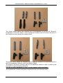
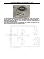
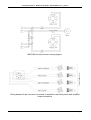
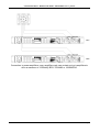
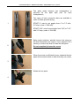
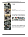
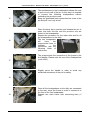
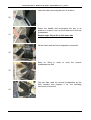
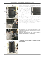
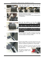
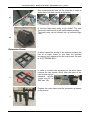
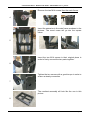
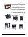
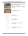
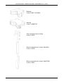
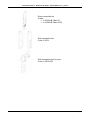
“OUTLINE BUTTERFLY / MANTAS LINE ARRAY”
USER MANUAL
Ver 1.1_07/2013
“OUTLINE BUTTERFLY - MANTAS LINE ARRAY” USER MANUAL Ver 1.0_06/2013
The picture above shows the complete set of accessories to rig the first “Butterfly”
loudspeaker to the main frame, it also includes the shackle used to connect the motor to
the central bar (when used with a single motor).
The picture above shows the complete set of hardware required to connect the frame to
the first loudspeaker: Butterfly (Left) and Mantas (Right).
The shape of the back connection bars for the Mantas is studied in order to obtain a fast
connection of all the following elements.
Use the specified hardware in order to rig the system safely and faster.
The complete set of codes and parts is reported at the end of this document.
Page 2
“OUTLINE BUTTERFLY - MANTAS LINE ARRAY” USER MANUAL Ver 1.0_06/2013
The recommended speaker cables have one end (rack side) with a male 8-pole connector
and two Speakon NL4 (loudspeaker side). Each NL4 drives two butterfly in parallel or
three Mantas using 4-wire cable with one NL4 connector on each side. Please respect the
suggested amplifier configuration
In the diagrams below, we show the wiring diagram from inside the loudspeaker. We also
show the cabling configuration and the amplifier rack
Butterfly BFLY-CDH483 drivers/connector wiring diagram.
Page 3
“OUTLINE BUTTERFLY - MANTAS LINE ARRAY” USER MANUAL Ver 1.0_06/2013
MANTAS drivers/connector wiring diagram.
Wiring between 8-pin connector (mounted on amplifiers rack back panel) and amplifier
output connectors.
Page 4
“OUTLINE BUTTERFLY - MANTAS LINE ARRAY” USER MANUAL Ver 1.0_06/2013
Connection to power amplifiers: every amplifiers rack can contain up to six amplifiers to
drive a maximum of 12 Buttefly BFLY-CDH483 or 18 MANTAS.
Page 5
“OUTLINE BUTTERFLY - MANTAS LINE ARRAY” USER MANUAL Ver 1.0_06/2013
The splay angle between two loudspeakers is
selected via the back bars (two for each
loudspeakers)
Two types of back connection bars are available in
order to obtain precise aiming.
1
START 0°: used to set angles from 0° to 7.5° with
0.5° step. (code: V 530 A/B)
START 0.25°: used to set angles from 0.25° to 7.25°
with 0.5° step. (code: V 554 A/B)
Splay angle selection: partially loosen the screw on
the side connection bar using a 4 mm (approx 5/32”)
hex key in order to be able to rotate the two parts.
2
Do not completely loosen the screw.
When the screw is sufficiently loose, separate the two
parts with the small teeth in order that they can rotate.
3
Rotate the two parts.
4
Page 6
“OUTLINE BUTTERFLY - MANTAS LINE ARRAY” USER MANUAL Ver 1.0_06/2013
5
6
7
Select the desired splay angle according to the
simulation made in OpenArray and fasten the screw
using a small torque. The two parts have to be firmly
coupled.
Don’t use excessive torque to tighten the screw,
use just the force needed in order to have no
mechanical lash (although a very small lash is
admitted). This will facilitate the installation.
It is strongly suggested to prepare all the back
connection bars before starting the connection of the
line array elements.
Based on the data exported from OpenArray, connect
the shackle to the respective hole in the central bar of
the main frame (when using a single motor) or to the
two extreme hanging points marked by the red arrows
(when using two motors).
Check the fastening of each shackle and connect it to
the motor. In order to avoid disturbance from the
motor’s chain bag, use a short steel cable.
The motors and all the accessories used to rig the
line array have to respect the loads stated in the
OpenArray mechanical report for the particular
configuration.
Raise the frame in order to prepare connection of the
first group of loudspeakers.
8
9
Position the first two back connection bars (V568 for
Butterfly, V861 for Mantas): pull the handle to extract
the pin, place the bar and release the handle in order
to set the pin in its normal working position.
Slightly screw the handle in order to avoid any
accidental movement of the pin for safety.
Page 7
“OUTLINE BUTTERFLY - MANTAS LINE ARRAY” USER MANUAL Ver 1.0_06/2013
Frame details:
1 – handle
2 – bar place
3 – bar in the working position
2
1
10
3
11
Move the flight-case with the loudspeaker close to the
rigging structure.
Standard flight-cases can either house three or four
loudspeakers.
Remove the flight-case cover and prepare the pack of
loudspeakers into position to be rigged. Prepare also
all the speaker cables (not shown here) and remove
the side bars from their rest position.
12
Prepare the pairs of back connection bars previously
set for each loudspeaker.
13
14
Connect the frame to the first loudspeaker by means
of the two bars previously connected (point 9).
The image shows the connection of a Butterfly
loudspeaker to the frame (the bar V568 is used).
Page 8
“OUTLINE BUTTERFLY - MANTAS LINE ARRAY” USER MANUAL Ver 1.0_06/2013
15
16
The mechanisms on the loudspeakers allows the user
to pull out only half of the pin. In this way it is possible
to connect the following loudspeakers without
unhooking the previous ones.
Bring the graduated back connection bar close to the
pin and pull it out only a half.
Place the back bar in position and release the pin in
order that both this bar and the previous one are
locked to the loudspeaker.
Repeat this procedure for the other side and for all
the loudspeakers on the dolly.
The last loudspeaker
will
have
two
unconnected bars to
facilitate
the
connection with the
following block of
enclosures.
The image shows the connection of the frame to the
first Mantas. Please note the use of the S-shaped bar
(code V861).
17
Slightly screw the handle in order to avoid any
accidental movement of the pin for safety.
18
19
Once all the loudspeakers on the dolly are connected
to the rear, lower the frame in order to connect it to
the front of the first loudspeaker.
Prepare two main frame side connecting bars (V
556).
Page 9
“OUTLINE BUTTERFLY - MANTAS LINE ARRAY” USER MANUAL Ver 1.0_06/2013
Insert the side connecting bar into its location.
20
Screw the handle and accompany the bar in its
position in order to lock it to the frame and to the first
loudspeaker.
21
Repeat steps 20 and 21 on the other side
Lift the frame and the first loudspeaker connected.
22
Keep on lifting in order to raise the second
loudspeaker as well.
23
One per side: grab the second loudspeaker by the
front handles and prepare it for the following
connection to the front.
24
Page 10
“OUTLINE BUTTERFLY - MANTAS LINE ARRAY” USER MANUAL Ver 1.0_06/2013
Insert the side connection bar into its location.
Slide the safety mechanism upwards, slide inside the
connection bar and release the spring mechanism.
Do not force the insertion of the
side bar for any reason.
When this operation is correct it
does not require any stress and
any physical strain.
Check the actual position of the
safety device before continuing
the other operations
25
There are two types of side connecting bars, the
only difference is the handle. Both are able to be
used.
The image shows both bars. Most recent on the left
and the older one on the right.
26
1
2
27
3
Safety device during the insertion of the side bar.
Slide upwards the device with the fingers and then
insert the side bar. Make sure when the side bar is
completely inserted, the device has to be located
back into its starting position. This will avoid the side
bar from accidentally coming out.
Repeat the previous operations
loudspeakers on the dolly.
28
for
all
the
Repeat all the actions on both sides of the
loudspeaker.
If it is impossible to connect the side bars please
check the angles on the back bars.
Page 11
“OUTLINE BUTTERFLY - MANTAS LINE ARRAY” USER MANUAL Ver 1.0_06/2013
Verify all the connections, the line array should look
like the one in the image on the left.
29
The side connection bar
must be in place like the
image on the right, with the
handle towards the bottom.
In this position the space
between the loudspeakers'
waveguide should be around
2 mm (1/16”).
After lifting the first group of loudspeakers, bring the
second flight case to the flown system.
Connect the back bar hooked to the last flown
loudspeaker to the first loudspeaker on the dolly.
Connect the back of the loudspeakers on the dolly as
shown for the first group of loudspeakers.
30
31
Lift the system and connect the side bars on the
loudspeakers following the same procedure shown for
the previous group.
Repeat the operations from #22 to #31 in order to
complete the installation of the line array.
A six-element line-array ready to be lifted up to the
working position
32
Page 12
“OUTLINE BUTTERFLY - MANTAS LINE ARRAY” USER MANUAL Ver 1.0_06/2013
The same system with the cabling in place. Please
remember to follow the instructions given for the
connection of the loudspeakers
33
Dismantling
The dismantling of the system is basically the inverse of assembly. There are a couple of
points that require special attention in order to avoid damage to some parts.
Before starting the dismantling procedure lower the array to a convenient height.
34
One per side: grab the side handle in order to hold
the loudspeaker once the side bars have been
removed.
With the other hand grab the handle of the side bar,
unlock the safety device by sliding it upwards and
remove the side bar.
Follow the loudspeaker through the vertical position
and repeat steps 34 and 35 for the loudspeakers that
have to stay on the same dolly (three or four).
35
Page 13
“OUTLINE BUTTERFLY - MANTAS LINE ARRAY” USER MANUAL Ver 1.0_06/2013
Lower the entire system in order to put the
loudspeakers on the dolly.
36
37
38
Remove the back bar from the first loudspeaker on
the dolly from the flown system.
Repeat steps 34, 35 and 36 for the remaining blocks
of loudspeakers.
When the last module is on the dolly, before
proceeding with the following steps, please be
sure that the chain connected to the motor is NOT
under tension. Otherwise you must lower the
motor, so that no load is taken by the lifting point.
Don't remove the adjustable bars connected on
the rear of the loudspeakers in order to avoid the
overturning of the frame and the first loudspeaker
of the block.
After checking that the cable connected to the frame
is not in tension, unscrew the handles of the side
connections bars to the frame (V556).
39
Keep the bar parallel to the frame with the aid of the
hand, as shown in the image on the left. In order to
remove it remember to grab the bar, not the handle.
40
If the bar is difficult to remove don’t use force, since
this will result in a much more difficult operation
during this phase.
This handle is designed only
to tighten the screw, not to
pull the bar.
Page 14
“OUTLINE BUTTERFLY - MANTAS LINE ARRAY” USER MANUAL Ver 1.0_06/2013
Any remaining side bars can be removed in order to
place them into their normal rest position.
41
A four-box flight-case ready to be closed. The side
connection bars are all in the rest/transport position.
The back bars can be placed into an external flight
case.
42
Extension Frame
1
2
In some cases the aiming of the system requires the
use of a longer frame. In this case the required
accessory is an extension for the main frame. Its code
is A EXTFRAME-BFLY.
In order to connect the accessory to the main frame
remove the two screws (M14) from the back of the
main frame using a
standard wrench
(metric size 22, or
SAE size 7/8).
Prepare the main frame and the extension as shown
in the picture.
3
Page 15
“OUTLINE BUTTERFLY - MANTAS LINE ARRAY” USER MANUAL Ver 1.0_06/2013
Remove the two M14 screws from the main frame.
4
Insert the extension in the main frame as shown in the
pictures. The round noses will go into the square
tubes.
5
Insert the two M14 screws in their original place in
order to firmly connect the two parts together.
6
Tighten the two screws with a good torque in order to
ensure a steady connection.
7
The resultant assembly will look like the one in this
picture.
8
Page 16
“OUTLINE BUTTERFLY - MANTAS LINE ARRAY” USER MANUAL Ver 1.0_06/2013
9
In case of extreme array up-tilting, the extension can
also be connected to the front of the main frame.
Remove the central bar by removing the two screws
(image on the left). If the application requires the use
with a single motor the central bar has to be
substituted by the specific shorter one (A BAR-254).
In case of up-tilting the extension frame can also be
mounted frontally to the mainframe. To do this you
need to remove the center bar
using the two fixing screws (see sidebar) and replace
it with the appropriate bar for frontal use. (A BAR-254)
Accessories
The rear connection bars, the special bars to connect
the frame to the first loudspeakers and some spare
parts can be stored in an external case. Specific
flight-cases are available upon request. They can
accommodate just the back bars or (as the one
shown in these pictures) they can also include two
frames plus two extensions.
Amplification racks: each rack is able to drive 12
Butterfly or 18 Mantas depending on the amplifier
configuration.
Page 17
“OUTLINE BUTTERFLY - MANTAS LINE ARRAY” USER MANUAL Ver 1.0_06/2013
25 m long cable to connect the amplifier rack with the
loudspeakers (SP2 LKI8-25). Each complete rack will
require three cables like this one.
Alternatively, for fixed installations, it is possible to
use 4-wire cables. Please ask for any specific
requirements.
0.7 m bridge cable for loudspeakers.
Code: A SPK 4X2.5-0.7
Main frame
Code: A MFRAME-BFLY
Extension Frame
Code: A EXTFRAME-BFLY
Short central support bar for frontal extension
Code A BAR-254
Long central support bar for rear extension
Code A BAR-332
Page 18
“OUTLINE BUTTERFLY - MANTAS LINE ARRAY” USER MANUAL Ver 1.0_06/2013
Butterfly
Code: O BFLY-CDH483
Mantas
Code: O MANTAS
Side connection bar to frame
Code: A V556
Rear connection bar to frame (Butterfly)
Code: A V568
Rear connection bar to frame (MANTAS)
Code: A V861
Page 19
“OUTLINE BUTTERFLY - MANTAS LINE ARRAY” USER MANUAL Ver 1.0_06/2013
Rear connection bar
Codes:
• A V530A-B (Start 0°)
• A V554A-B (Start 0.25°)
Side connection bar
Code: A V531
Side connection bar for rope
Code: A V552-553
Page 20
“OUTLINE BUTTERFLY - MANTAS LINE ARRAY” USER MANUAL Ver 1.0_06/2013
Maintenance and control
The equipment and accessories must be regularly tested by expert staff, at least once
every three months. For the structure and the accessories provided (pins, brackets, etc.), a
special register must be used (example shown in Annex N° I). This register must be kept
up to date, writing the result of the inspection and must be signed by the person carrying
out the actual control.
In the event of any “irregularity” occurring, use of the device must be stopped, to enable an
accurate examination to be carried out by expert technicians.
Various types of “irregularities” can occur. This following is just a list to facilitate their
possible identification; it must also be noted that these defects could also occur
simultaneously. The main ones are:
o oxidation and/or corrosion – widespread or limited to an element;
o fatigue cracks or localized deformations;
o buckling/deformation of the structure or elements (for example the ovalization of the
pins’ and pinions’ holes, bending of the brackets, etc.);
o wear (for example of the pins, pinions or contact zones);
o damage of the protective surface treatment, probable sign of an underlying crack;
o deterioration of the safety indications (red area on the rear brackets);
o etc.
The register must always be at the disposal of the authorities responsible for controls.
In particular, the following checks must be carried out for the rigging accessory:
o overall structure and, in particular, the elements’ welding;
o ovalization, deformation and/or cracks in the pinion holes;
o conditions of the fixing pins and pinions.
Removing from use
In the event of even just one of the following list of defects being found in any component
of the array, it must be immediately removed from use:
o cracks in any element of the structure;
o permanent deformations of the load-bearing structures;
o non-compliant results of the checks carried out.
Disposal and scrapping
If any component has to be scrapped for any reason, the disposal must be carried out by
authorized companies, and in compliance with the current regulations regarding this
matter.
Maintenance register
As anticipated in the chapter MAINTENANCE & CONTROL, for every frame and every
element, a special register must be realized, in which the periodical tests the structure and
relative accessories undergo will be noted. An example is shown in Annex N°1.
Page 21
“OUTLINE BUTTERFLY - MANTAS LINE ARRAY” USER MANUAL Ver 1.0_06/2013
Annex 1
FRAME TEST FORM
Model:
Date
Serial N°:
Frame
Frame
holes
Frame
Welding
Year:
Shackles
Rear
brackets
Side
brackets
Other / Notes
Signature
Page 22
“OUTLINE BUTTERFLY - MANTAS LINE ARRAY” USER MANUAL Ver 1.0_06/2013
Annex 2
EXTENSION FRAME TEST FORM
Model:
Date
Serial N°:
Frame
Frame
holes
Frame
Welding
Year:
Shackles
Rear
brackets
Side
brackets
Other / Notes
Signature
Page 23
“OUTLINE BUTTERFLY - MANTAS LINE ARRAY” USER MANUAL Ver 1.0_06/2013
Annex 3
Model:
Date
“Butterfly/Mantas” ELEMENT TEST FORM
Serial N°:
Year:
Side
Side
Side
Rear
Rear
Rear
Side & Rear
Safety
embedded embedded connection embedded embedded Connection
brackets
Devices
Brackets Brackets' Brackets
Brackets Brackets'
Holes
Pins
Notes
Signature
Page 24
“OUTLINE BUTTERFLY - MANTAS LINE ARRAY” USER MANUAL Ver 1.0_06/2013
TECHNICAL REFERENCE STANDARDS
All Butterfly/Mantas Line Array system components are designed and manufactured in conformity
with the following technical standards (where applicable):
Directive 2006/42/CE of 17th May 2006 "Machinery Directive", published in the Official Gazette - issue 331 of
07.12.1998.
Legislative Decree 17 of 27/01/10, “Implementation of Directive 2006/42/CE regarding machinery, and which modifies
directive
95/16/CE regarding lifts (elevators)”;
Legislative Decree 81 of 9/04/08, "Implementation of Art. 1 of law N° 123 of 3/08/07 on the matter of s afeguarding health
and
safety in workplaces” and later amendments regarding the improvement of safety and health of workers in workplaces;
Directive 2006/95/CE, “Low Voltage”;
Directive 2004/108/CE, “Electromagnetic Compatibility”;
Directive 2003/10/CE (Legislative Decree 195/06), "Protection from noise";
Legislative Decree 195 of 10/04/06, “Implementation of Directive 2003/10/CE regarding the exposure of workers to risks
arising
from physical agents (noise)”;
UNI EN ISO 12100 (2010), "Safety for machinery - General principles for design – Risk assessment and risk reduction";
UNI EN 13857 (2008), "Safety of machinery -- Safety distances to prevent hazard zones being reached by upper and
lower limbs";
UNI EN 349 (2008), "Safety of machinery - minimum gaps to avoid crushing of parts of the human body";
UNI EN ISO 13850 (2008), “Safety for machinery - Emergency stop - Principles for design”;
UNI EN 614-1 (2009), "Safety of machinery - Ergonomic design principles - Part 1: Terminology and general principles";
UNI EN 614-2 (2009), " Safety of machinery - Ergonomic design principles - Interaction between machinery design and
work tasks";
UNI EN 894-1 (2009), "Safety of machinery - Ergonomics requirements for the design of displays and control actuators General
principles for human interactions with displays and control actuators";
UNI EN 894-2 (2009), “Safety of machinery - Ergonomics requirements for the design of displays and control actuators –
Displays”;
UNI EN 894-3 (2009), “Safety of machinery - Ergonomics requirements for the design of displays and control actuators –
Control
actuators”;
UNI EN 953 (2009), “Safety of machinery – Guards - General requirements for the design and construction of fixed and
movable
guards”;
UNI EN 981 (2009), “Safety of machinery - Systems of auditory and visual danger and information signals”
UNI EN ISO 13849-1 (2008) "Safety of machinery – Safety-related parts of control systems – Part 1: General principles
for design";
UNI EN ISO 13855 (2010) “Safety of machinery - Positioning of protective equipment with respect to the approach
speeds of parts of
the human body”
UNI EN 1037 (2008), "Safety of machinery – Prevention of unexpected start-up";
UNI EN 1760-2 (2009), "Safety of machinery - Pressure sensitive protective devices - Part 2: General principles for the
design and
testing of pressure sensitive edges”.
UNI EN ISO 4871 (2009) “Acoustics — Declaration and verification of noise emission values of machinery and
equipment”;
CEI EN 60204-1 (2006), (CEI 44-5), "Safety of machinery - Electrical equipment of machines - Part 1: General rules";
CEI EN 60947-1 (2008), (CEI 17-44), "Low-voltage switchgear and control gear - Part 1: General rules";
CEI EN 60446 (2008), (CEI 16-4), "Basic and safety principles for man-machine interface, marking and identification Identification
of conductors by colours or alphanumerics”;
CEI EN 61310-1 (2008), (CEI 44-5), “Safety of machinery - Indication, marking and actuation - Part 1: Requirements for
visual,
acoustic and tactile signals”;
CEI EN 61310-2 (2008), (CEI 44-5), “Safety of machinery - Indication, marking and actuation - Part 2: Requirements for
marking”;
UNI EN 1990 (2006), “Eurocode - General structural design criteria”;
UNI EN 1991-1-1 (2004), “Eurocode 1 – Actions on structures - Part 1-1: General actions – Densities, self-weight and
imposed loads
for buildings”
UNI EN 1993-1-1 (2005), “Eurocode 3 - Design of steel structures – Part 1-1: General rules and rules for buildings”
Page 25