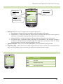
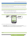
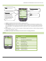
1
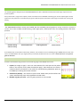
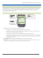
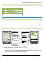
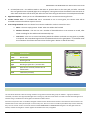
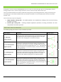
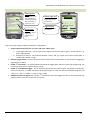
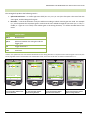
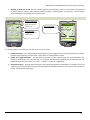
w www.fusionsport.com ADVANCED PROTOCOL GUIDE Version 3.1, February 2011. Please check website for updates PO BOX 56 | 2 Henley Street | Coopers Plains | QLD, 4108 | Australia | PH: (+61 7) 3344 6599 | FAX (+61 7) 3344 5076 SMARTSPEED and SMARTSPEED LITE Advanced Protocol Guide Introduction ___________________________________________________________________________ 2 “TRACK” Protocol Family (SMARTSPEED and SMARTSPEED LITE Systems) __________________________ 2 Standard Timing ________________________________________________________________________ 3 Traffic Light Sprints _____________________________________________________________________ 4 Reactive Mat Start ______________________________________________________________________ 5 Free Timing Mode ______________________________________________________________________ 6 Chute Protocol _________________________________________________________________________ 7 TRACK RETURN (INTERVAL) PROTOCOLS – SMARTSPEED AND SMARTSPEED LITE ____________________ 9 CUTS (SMARTSPEED or hybrid systems only) ________________________________________________ 11 6 Gate Cut (0‐1‐2‐3) ____________________________________________________________________ 14 Reactive Shuttle Drill ___________________________________________________________________ 14 Reactive Shuttle Interval Drill ____________________________________________________________ 16 Reaction Time Cut Drill __________________________________________________________________ 18 Serpentine Drills (SMARTSPEED or hybrid systems only) _______________________________________ 20 GRID DRILLS (4 and 6 gate; SMARTSPEED systems only ________________________________________ 21 LAP DRILLS (SMARTSPEED and SMARTSPEED LITE systems) ____________________________________ 22 Standard Lap Timing ___________________________________________________________________ 22 Lap Interval Drills ______________________________________________________________________ 24 Pro Agility Drill ________________________________________________________________________ 25 PACING – 2 OR 4 gATE (SMARTSPEED ONLY) ________________________________________________ 27 JUMPING TEST FEEDBACK MODE (SMARTSPEED and SMARTSPEED LITE)* ________________________ 29 TAPPING TEST – SMARTSPEED systems only _________________________________________________ 29 FINAL WORD – register your product ______________________________________________________ 31 © 2010 Fusion Sport International 1 SMARTSPEED and SMARTSPEED LITE Advanced Protocol Guide INTRODUCTION The following guide is designed to provide SMARTSPEED users with a detailed overview of the wide range of protocols and protocol options. Each protocol has a range of user options, which are located on the “OPTIONS” tab during your session. Exploring the various options for each protocol is an excellent way to get to know the system and create a wide range of variations for training and testing. “TRACK” PROTOCOL FAMILY (SMARTSPEED AND SMARTSPEED LITE SYSTEMS) The SMARTSPEED software arrives pre‐installed with five standard protocol groups for testing acceleration, speed and reaction time. These include standard timing, traffic light sprint, reactive/mat start, free timing protocol, and chute protocol. Standard Timing and Free Timing Reactive/Mat Start Traffic Light Sprints Chute Protocol Pre‐installed drills are included in each family; however, new variations can be created by going to NEW/Protocol on the main menu. The PDA software has up to 6 gate sprints pre‐installed, however the user can create a NEW PROTOCOL with up to 12 gates on one lane. PROTOCOL SETTINGS Variations of standard timing protocols can be made by going to the NEW/Protocol menu. 1. Layout (see image to right) – users can enter distances for each split into the yellow boxes in the top left corner (when finished hit apply). These distances are used to calculate velocity calculations in the results for standard timing. Additional splits can be added by increasing the number of boxes. 2. Subsessions (details) – the number of sprints each athlete must perform before the system automatically stops. Only applicable in AUTO mode 3. Number of gates per track – up to 12 gates protocols can be created. © 2010 Fusion Sport International 2 SMARTSPEED and SMARTSPEED LITE Advanced Protocol Guide STANDARD TIMING DESCRIPTION Standard timing drills use a start gate, split gates (if desired) and a finish gate. Each lane (track) must have a start and finish gate as the minimum. The user can then select the appropriate number of gates to provide the desired split times. For example, to run a 40 meter sprint with 10 and 20 meter splits, the 4 GATE SPRINTS protocol should be selected. The athlete must run through the gates in order from start to finish. USER OPTIONS Break algorithm control Control the break algorithm Start type Select different start type (Auto/In beam start /Switch mat up) Winner mode Show winner in multiple track after all athletes finish. 1. Start Type: allows the user to configure the start type for the session – a. Auto (default): timing starts when the athlete in each lane breaks the first gate b. Mat/Switch up – timing starts when the athlete lifts their hand/foot OFF the start mat or hand start pad (note – a start pad or switch must be connected to the start gate) c. Mat/Switch down – timing starts when the athlete steps ON to the start mat or starts switch d. In beam/mat start – the athlete stands in the beam, or presses down on the start pad, and after 3 seconds the start gate becomes activated (light turns solid green). Timing starts when the athlete leaves the beam or when their hand comes off the start pad. 2. Algorythm ON/OFF – allows you to turn off SMARTSPEED’s Error Correction Processing function 3. Show Winner – when running multiple lanes, ticking this option will cause the system to show the winner of each subsession by flashing the lights and or sounding the buzzers on the fastest athlete’s lane. © 2010 Fusion Sport International 3 SMARTSPEED and SMARTSPEED LITE Advanced Protocol Guide RESULTS OUPUT ITEM DESCRIPTION Split Individual split results (seconds) Total Individual split results (seconds) Velocity The Velocity for each split in units/second) NOTE: for velocity to be accurate the user must enter the correct distances by creating a NEW PROTOCOL and entering the correct distances in the protocol TRAFFIC LIGHT SPRINTS DESCRIPTION Traffic light sprints involve the athlete starting from a position, without the use of a start gate. Timing is initiated by the system signaling “GO” and the athlete then sprints through to the finish gate. Intermediate “split” gates can also be used. Traffic light sprints are ideal for use in training as they do not require the use of a start gate, and therefore more lanes can be set up for faster throughput. Up to 8 lanes can be used on one PDA, creating a competitive challenge for your athletes. USER OPTIONS Traffic Light Start Control Select different start type (Light/Buzzer) and the random or fixed start delay period Break algorithm control Control the break algorithm 1. The type of reactive start signal (Light, Buzzer or Both) 2. Algorythm ON/OFF – allows you to turn off SMARTSPEED’s Error Correction Processing function © 2010 Fusion Sport International 4 SMARTSPEED and SMARTSPEED LITE Advanced Protocol Guide RESULTS ITEM DESCRIPTION Split Individual split results (seconds) Total Individual split results (seconds) SPECIAL NOTE – SMARTSHOXX INTEGRATION FOR ATHLETICS STARTS Using a SMARTSHOXX sensor attached to the first split gate users can record a highly specific measurement of reaction time for athletics starts. By attaching the SMARTSHOXX sensor to the sprint start blocks, the time from the reactive signal until the first movement/vibration of the sprint blocks will be recorded as the first split. Furthermore, if the athlete performs a false start the system will record an error for the test. REACTIVE MAT START DESCRIPTION Reactive/Mat Start Sprints are a variation of standard timing with the addition of a reaction time measurement on the start gate. This protocol requires the connection of a hand start pad or SMARTJUMP mat to the start gate. The default protocol on your PDA is using 2 gates, however if you wish to add additional gates, simply create a NEW PROTOCOL and select the desired number of gates. USER OPTIONS: Traffic Light Start Control Select different start type (Light/Buzzer) and the random start delay period Break algorithm control Control the break algorithm In addition to the options available for standard timing, the user can configure 3. The type of reactive start signal (Light, Buzzer or Both) 4. The delay between the athlete being set (i.e. being on the start pad for 2 seconds) and the reactive start signal occurring. This delay can either be a set time, or a time range 5. Break algorithm ON/OFF © 2010 Fusion Sport International 5 SMARTSPEED and SMARTSPEED LITE Advanced Protocol Guide RESULTS OUPUT: ITEM DESCRIPTION R.Time Reaction time (seconds) Split Individual split results (seconds) Total Total time (seconds) FREE TIMING MODE DESCRIPTION Free timing provides complete freedom with your test design, as it does not require athletes to run through the gates in a set order. Gates can be passed multiple times, and in any order, depending on the settings you choose. If you are in doubt about how to run a particular test, then begin by using Free Timing Mode – essentially it can be used to time anything. USER OPTIONS Include contact time calculation Record contact time as well when mats are detected. Free Timing standard Select training mode (Free mode / Set number of events / time limit) Start type Select different start type (Auto, In beam, Switch mat down/up, In beam mat start) Test protocell alignment Set trigger directions (Fix/Random) Gate rearm delay Control the photocell rearm period Break algorithm control Control the break algorithm 1. Start Type: allows the user to configure the start type for the session – a. Auto (default): timing starts when the athlete in each lane breaks the first gate b. Mat/Switch up – timing starts when the athlete lifts their hand/foot OFF the start mat or hand start pad (note – a start pad or switch must be connected to the start gate) c. Mat/Switch down – timing starts when the athlete steps ON to the start mat or starts switch © 2010 Fusion Sport International 6 SMARTSPEED and SMARTSPEED LITE Advanced Protocol Guide d. In beam/mat start – the athlete stands in the beam or presses down on the start pad, and after 3 seconds the start gate becomes activated (light turns solid green). Timing starts when the athlete leaves the beam or when their hand comes off the start pad. After the start event the gate will return to normal photocell mode. 2. Algorithm ON/OFF – allows you to turn off SMARTSPEED’s Error Correction Processing function 3. Include Contact Time – if a SMARTJUMP mat is connected to one or more gates, the contact time will be recorded each time the athlete steps on the mat. 4. Free Timing Standard: users can choose from various standards in order to control the test – a. None – the user simply presses “STOP” when the athlete has finished b. Number of events – the user can set a number of desired breaks or mat contacts to record, after which recording for that athlete will automatically stop c. Time Limit – user can set a time limit during which the athlete can break as many gates as possible, as required. The countdown begins when the athlete breaks the first gate (NOTE – in multilane mode the countdown for all lanes will start when the first gate is broken in ANY of the lanes) RESULTS ITEM DESCRIPTION Index Break index Gate Broken gate ID Type Break type (split time / contact time Split/CT Split time in seconds/ contact time in milliseconds Total Total time (seconds) CHUTE PROTOCOL DESCRIPTION The new Chute Protocol is ideal for timing medium to long distance events with groups of athletes. A group of athletes is started by a common start signal (traffic light start or start gun), and then finish chutes are used to record the finishing time of athletes using a combination of finish gates and Smartscan RFID readers. Once the user presses “GO” on the PDA, the lights at the finish line will all flash and make a loud sound to start the event. The athletes then run the event (for example a cross country race, 3km run or even a marathon) and when they come to the finish, they run into a finish “chute”. Each chute consists of two SMARTSPEED or SMARTSPEED LITE gates. The first gate times the athlete, and the second gate is used to register the athlete to the time, using RFID. © 2010 Fusion Sport International 7 SMARTSPEED and SMARTSPEED LITE Advanced Protocol Guide The procedure is therefore ‐ 1. Each athlete selects an available chute to run through to finish 2. After running through to finish, the athletes line up in order in their chute 3. In turn, each athlete swipes their RFID wrist band. If successful, the unit will beep. The athlete’s time and name have then been saved 4. If an athlete tries to swipe in twice the unit will beep again but will ignore the band 5. When all athletes have finished press stop to end the session. All results will be visible in the table tab USER OPTIONS Break algorithm control Control the break algorithm Start type Select different start type (Traffic light start / Gun start when the system detects SMARTGUN) Traffic Light Start Control Select different start type (Light/Buzzer) and the random start delay period Chute management Test and control chutes 1. Break algorithm on/off (as per standard timing) 2. Start type – light, buzzer or both 3. Random start period – set a fixed or random range for the delay between pressing GO, and the gates signaling the start 4. Chute Setting – if you no longer need all chutes, or perhaps one or more chutes is running low on battery power, you can close the chute by pressing red symbol next to the chute. The Chute Settings also display the ID of the gate, and RFID gate in each chute (5 and 7 in this example). SET‐UP NOTES When setting up the Chute protocol, you will require 2 gates per chute, one for timing and one for RFID. During the “test track” phase, go through the chutes in order to register them on the system (gate first, then RFID gate). RESULTS ITEM DESCRIPTION Total Total time (seconds) © 2010 Fusion Sport International 8 SMARTSPEED and SMARTSPEED LITE Advanced Protocol Guide TRACK RETURN (INTERVAL) PROTOCOLS – SMARTSPEED AND SMARTSPEED LITE Track return drills use 2 gates per lane to run automated interval protocols. One example is included pre‐installed in the software, however users can create new protocol with different repetition numbers and work:rest ratios. Unlike Standard Timing drills, Track Return drills allow athlete to run in either direction in the lane; therefore they can run one way, rest, and then return the other way in the next period. PROTOCOL VARIATIONS Users can create new protocols by entering the NEW/Protocol menu and choosing “Track return/Interval Drills” as the parent drill. New protocols can then be created by changing the following settings – 1. Subsessions – the number of repetitions to be completed 2. Period – the total time for each interval, including the sprint, and the remaining recovery period. Athletes must perform one sprint during each period, and have the remainder of the period to rest. IMPORTANT NOTE – FIXED RECOVERY PROTOCOLS Track return protocols used a fixed PERIOD method (i.e. if the period is 30 seconds, and the athlete sprints for 6 seconds, they then have the remaining 24seconds to recover). This method allows SMARTSPEED to run up to 8 lanes at the same time on one PDA, as all lanes can run off the same master countdown clock. Some protocols however, use fixed recovery periods (for example, no matter how long the athlete takes to perform the sprint, they always have 25 seconds rest). If you wish to run a protocol with a fixed recovery period, the best method for this is using FREE TIMING MODE. Set the total test duration (for the whole test) and then the system will record the sprints, and recovery periods. However if running multiple lanes, an assistant will be required to manually time the recovery period in each lane. If you would like more information about this approach please contact [email protected] USER OPTIONS: Break algorithm control Control the break algorithm Customized subsession period Set the period of each repetitions in seconds individually if required © 2010 Fusion Sport International 9 SMARTSPEED and SMARTSPEED LITE Advanced Protocol Guide Several user options are available in Track Return mode – 1. Break algorithm on/off – as per standard timing 2. Manually adjust each period – the length of each period can be individually adjusted, in addition to what you have configured in the protocol. RESULTS OUPUT: ITEM DESCRIPTION Split Individual split results (seconds) Index The number of the repetition amongst the set During the session, the sprint number, most recent time and average time for all sprints is displayed on the results tab (see image, right). © 2010 Fusion Sport International 10 SMARTSPEED and SMARTSPEED LITE Advanced Protocol Guide CUTS (SMARTSPEED OR HYBRID SYSTEMS ONLY) Cutting drills are the first family of SMARTSPEED drills to use reactive sound and/or light signals to challenge agility, decision making, peripheral vision, reactive change of direction, evasion and visual and/or audio reaction time. There are hundreds of different variations possible with cutting drills by manipulating dimensions, setting and coaching rules. The following is an overview of the default drills pre‐installed on the PDA. For more examples, please visit the Fusion Sport members’ area. There are basically 2 types of cutting drills – 1. Single repetition cutting drills – the athlete performs one repetition by starting at the start and running through to the finish 2. Interval type cutting drills – involving multiple repetitions (intervals) of cutting movements for more complicated intermittent protocols. SINGLE REPETITION CUTTING DRILLS The following cutting drill variations are pre‐installed on your PDA ‐ Protocol Name Description 1‐1‐2 Auto Start Timing starts when athlete breaks first gate. As athlete breaks second gate, athlete must react and finish through either the 3rd or 4th gate (pictured as left and right gates in the default example). Sample Layout (4 gates required) 0‐1‐2‐1 Traffic Light Start (4 gates required) 0‐1‐3 Traffic Light Start (4 gates required) 0‐1‐2‐3 Traffic Light Start (6 gates required) Athlete starts a set distance back from first gate. Timing starts with visual and/or audio signal from first gate. As athlete breaks first gate, athlete must react and run through either the 2nd or 3rd gate (pictured as left and right gates in the default example), and then run through the 4th gate to finish. Athlete starts a set distance back from first gate. Timing starts with visual and/or audio signal from first gate. As athlete breaks first gate, athlete must react and run through either the 2nd, 3rd or 4th gate (pictured as left, middle and right gates in the default example). Athlete starts a set distance back from first gate. Timing starts with visual and/or audio signal from first gate. As athlete breaks first gate, athlete must react and run through either the 2nd or 3rd gate (pictured as left and right gates in the default example), and then react again and run through the 4th,5th or 6th gate to finish. © 2010 Fusion Sport International 11 SMARTSPEED and SMARTSPEED LITE Advanced Protocol Guide USER OPTIONS Traffic Light Start Control Select different start type (Light/Buzzer) and the random start delay period (0‐1‐3 and 0‐1‐2‐1 only) Reactive trigger response Control the reactive trigger type (Light/Buzzer or both) Reactive trigger delay Control the reactive trigger delay period (Fix/Random) Trigger direction Set trigger directions (Fix/Random) There are a wide range of options available for cutting drills – 1. Traffic Light Start Control (0‐1‐3, 0‐1‐2‐1 and 0‐1‐2‐3 drills only) – a. Traffic Light Start Type ‐ set the type of start signal to be a green light (“Light”), sound (“Buzzer”), or both (“Light/Buzzer) b. Random Start Period ‐ set the delay between “ready” and “go” signal to be either a fixed value, or random value within a range 2. Reactive Trigger Mode ‐ control the type of reactive signal made to the athlete as they break the trigger gate (Light, Buzzer or Both) 3. Enable 1st Level Delay – set a delay between breaking the trigger gate, and the reactive signal appearing. Can be either a fixed value or random within a range 4. Enable 1st Level Manual Trigger – set the direction (option) for the reactive signal. The default is random (R). Users can choose 0, 1, 2 which will select the respective gate in order that the user walked through the test track (i.e. 0 = left, 1 = middle, 2 = right on a 0‐1‐3 drill) 5. Additional options on 6 gate cut – enable 2nd level delay and manual trigger direction is also available for the 6 gate protocol as there are two levels of reaction. © 2010 Fusion Sport International 12 SMARTSPEED and SMARTSPEED LITE Advanced Protocol Guide RESULTS The cutting drills produce the following results – 1. Split and total times – on traffic light start drills (0‐1‐2‐1, 0‐1‐3, 0‐1‐2‐3) the first split is the time from the start signal, until breaking the first gate 2. Direction – records the direction ran by the athlete according to which reactive gate was used. For example 0, 1, 2 will represent the respective gate in order that the user walked through the test track (i.e. 0 = left, 1 = middle, 2 = right on a 0‐1‐3 drill). If the athlete goes in the wrong direction, “X” will be recorded next to the result. ITEM DESCRIPTION Split 1 Reaction time Split 2 Split time between the start gate and the trigger gate L/R Trigger direction** Total Total time **Note – the system will also record if the athlete went in the wrong direction in response to the reactive signal. In this case, the results page will show a red box where the mistake was made, and in the results the run will be marked with an “x”. 0‐1‐3 Correct Run: athlete went in correct direction 0‐1‐3 Incorrect Run: athlete went in wrong direction 0‐1‐2‐1 Correct Run: athlete went in correct direction 0‐1‐2‐1 Incorrect Run: athlete went in wrong direction © 2010 Fusion Sport International 13 SMARTSPEED and SMARTSPEED LITE Advanced Protocol Guide 6 GATE CUT (0‐1‐2‐3) ADDITIONAL USER OPTIONS Traffic Light Start Control Select different start type (Light/Buzzer) and the random start delay period Reactive trigger response Control the reactive trigger type (Light/Buzzer) Reactive trigger delay (1st level) Control the reactive trigger delay period (Fix/Random) Trigger direction (1st level) Set trigger directions (Fix/Random) Reactive trigger delay (2nd level) Control the reactive trigger delay period (Fix/Random) Trigger direction Set trigger directions (Fix/Random) The 0‐1‐2‐3 drill has similar options to the 4 gate varieties, however is also has an additional level of setting for the second cut – to set the reactive delay, and the direction for the second reactive event. REACTIVE SHUTTLE DRILL DESCRIPTION Originally created for tennis, the Reactive Shuttle Drill is the most basic multiple repetitions cutting drill. The athlete is required to perform a set number of shuttles between a home gate and a range of reactive gates. The default drill is using 6 gates, however new protocols can be configured by the user for fewer gates. Originally a SMARTJUMP mat was connected to the “home” gate for use in tennis; however a normal gate with beam can be used instead. PROCEDURE: 1. The athlete begins by breaking the “home” gate, either by breaking the beam, or by stepping onto the jump mat. 2. The athlete must then run to the gate which lights up (or hit a SMARTSHOXX target) to break the gate and then return to the home gate. 3. The athlete performs repeated shuttles between the home and reactive gates depending on the protocol settings. PROTOCOL SETTINGS: The following terms relate to the configuration of the drill when making new version so the drill using the NEW/PROTOCOL menu Subsessions: the number of shuttles to be performed by each athlete (i.e. the number of out and back movements). The default is 10 subsessions. © 2010 Fusion Sport International 14 SMARTSPEED and SMARTSPEED LITE Advanced Protocol Guide Number of Gates per Track: sets the number of gates you would like to use for the protocol. One gate will be required as the “home” gate, and then add the number of reactive gates. For example, a version with 4 gates would have 1 home gate and 3 reactive gates. USER OPTIONS: Reactive trigger delay Control the reactive trigger delay period (Fix/Random) Trigger direction Set trigger directions (Fix/Random) Gate rearm delay Set gate rearm period The following options are available on the options tab during the session ‐ 1. Enable Cut Delay – set a delay between breaking the “home” trigger gate (or leaving the jump mat), and the reactive signal appearing. Can be either a fixed value or random within a range. 2. Enable Set Trigger Manually – set the direction (option) for the reactive signal for each subsession. The default is random (R). Users can choose 0, 1, 2 etc which will select the respective gate in order that the user walked through the test track (i.e. 0 = left, 1 = middle, 2 = right on a 4 gate drill) 3. Gate Rearm Delay – set how quickly the gate rearms after being broken. The default is 1 second. A user may need to alter the re‐arm delay in some circumstances if the athlete movements are too fast for the system to record. This would be used rarely. © 2010 Fusion Sport International 15 SMARTSPEED and SMARTSPEED LITE Advanced Protocol Guide RESULTS ITEM DESCRIPTION Subsession The number of each shuttle or repetition Split 1 Split time between the reactive gate and back to the “home” gate Split 2 Split time between the reactive gate and back to the “home” gate Gate** The reactive gate which the athlete had to run to/hit Total Total time for each shuttle – the sum of splits 1 and 2 for each shuttle **NOTE: Gate –records the direction ran by the athlete according to which reactive gate was used. For example 1, 2, 3 will represent the respective gate in order that the user walked through the test track from left to right in a 4 gate version (0 is the home gate). REACTIVE SHUTTLE INTERVAL DRILL DESCRIPTION The Reactive Shuttle Interval drill was originally designed for a research project in Squash however is an excellent protocol for many sports. This protocol is unique in that it is the first protocol to trial the “kill time” concept, which due to its popularity will soon be introduced into a range opf other SMARTSPEED protocols. PROCEDURE (5 GATE VARIATION PICTURED) 1. The athlete begins by breaking the “home” gate, either by breaking the beam, or by stepping onto the jump mat. 2. The athlete must then run to the gate which lights up (or hit a SMARTSHOXX target), break the gate and then return to the home gate. The athlete performs as many shuttles as possible between the home and reactive gates during each work period. 3. Red lights will be displayed to signify the rest period between subsessions. 4. The athlete must complete all subsessions © 2010 Fusion Sport International 16 SMARTSPEED and SMARTSPEED LITE Advanced Protocol Guide NEW PROTOCOL SETTINGS: The default drill variation is designed for 5 gates – one ‘home’ gate (either a normal gate or gate with SMARTJUMP mat or SMARTSHOXX sensor attached), and 4 reactive gates. Other variations of the drill can be configured by creating a “new protocol”. The following terms relate to the configuration of the drill when making new version so the drill using the NEW/PROTOCOL menu ‐ Subsessions: the number of work intervals to be performed by each athlete (i.e. the number of work periods). The default is 6 subsessions. Number of Gates per Track: sets the number of gates you would like to use for the protocol. One gate will be required as the “home” gate, and then add the number of reactive gates. For example, a version with 4 gates would have 1 home gate and 3 reactive gates. Work Duration: the duration of each work period (subsession) during which the athlete is active. The default work duration is 30 seconds. USER OPTIONS: Reactive trigger delay Control the reactive trigger delay period (Fix/Random) Gate rearm delay Set gate rearm period Kill time If athlete cannot reach the trigger in the set period then the split will be cancelled Rest duration Break period between subsessions The following options can be set in the ‘options’ tab prior to commencement of the session. 1. Enable Cut Delay: a configurable option that can set a delay between breaking the home gate, and the illumination of the reactive gate. 2. Gate rearm delay (advanced): adjusts how quickly the gate will rearm after being broken 3. Kill Time: a configurable time limit for the athlete to reach each reactive gate after triggering the ‘home’ gate. If the athlete does not reach the reactive gate within the kill time, no result is recorded and the home gate will illuminate green. The athlete must break the home gate to activate the next reactive target. This can be set in the ‘options’ tab prior to commencement of the session. 4. Rest Duration: the duration of the rest period between work intervals. © 2010 Fusion Sport International 17 SMARTSPEED and SMARTSPEED LITE Advanced Protocol Guide RESULTS ITEM DESCRIPTION Subsession The number of each shuttle or repetition Split 1 Split time between the reactive gate and back to the “home” gate Split 2 Split time between the reactive gate and back to the “home” gate Gate** The reactive gate which the athlete had to run to/hit Total Total time for each shuttle – the sum of splits 1 and 2 for each shuttle **NOTE: Gate –records the direction ran by the athlete according to which reactive gate was used. For example 1, 2, 3 will represent the respective gate in order that the user walked through the test track from left to right in a 4 gate version (0 is the home gate). Also NOTE – if a kill time is set for the protocol, no result will be recorded when an athlete does not reach the reactive gate in less than the kill time. REACTION TIME CUT DRILL DESCRIPTION The reaction time cut drill is similar to the reactive shuttle drill, with the addition of a turning measurement at each reactive gate, and the measurement of simple reaction time from the start “home” gate. The athlete may also rest between subsessions. NOTE – for this protocol a SMARTJMP mat must be used at the “home” gate. PROCEDURE 1. On the blue light signal the athlete stands on the “home” gate jump mat. The athlete must then wait for the first reactive signal. 2. Upon receiving the reactive signal, the athlete must then run through the gate which lights up, turn at a marker or line, and return through the same gate, then run back to the “home” gate 3. The athlete then rests and returns to the mat during the red light period and repeats the procedure a number of times depending on the protocol settings. NEW PROTOCOL SETTINGS The following terms relate to the configuration of the drill when making new version so the drill using the NEW/PROTOCOL menu 1. Subsessions: the number of shuttles to be performed by each athlete (i.e. the number of out and back movements). The default is 6 subsessions. 2. Number of Gates per Track: sets the number of gates you would like to use for the protocol. One gate will © 2010 Fusion Sport International 18 SMARTSPEED and SMARTSPEED LITE Advanced Protocol Guide be required as the “home” gate, and then add the number of reactive gates. For example, a version with 4 gates would have 1 home gate and 3 reactive gates. The default drill uses 5 gates. USER OPTIONS: Reactive trigger delay Control the reactive trigger delay period (Fix/Random) Manual Trigger: Set the specific order of gates (default is random; R) Waiting period Break period between subsessions The following options are available on the options tab during the session ‐ 1. Delay Period – set a delay between the “ready” signal, and the illumination of the reactive gates 2. Enable Set Trigger Manually – set the direction (option) for the reactive signal for each subsession. The default is random (R). Users can choose 0, 1, 2 etc which will select the respective gate in order that the user walked through the test track (i.e. 0 = left, 1 = middle, 2 = right on a 4 gate drill) 3. Waiting Period – set the rest period between repetitions, during which the athlete must return to the home jump mat and be ready for the next subsession RESULTS ITEM DESCRIPTION Subsession The number of each shuttle or repetition R.Time The reaction time from when the reactive gate illuminates until the athlete leaves the start mat Split 1 Split time between the reactive gate and back to the “home” gate **NOTE: Gate –records the direction ran by the athlete according to which reactive gate was used. For example 1, 2, 3 will represent the respective gate in order that the user walked through the test track from left to right in a 4 gate version (0 is the home gate). Split 2 Turn time – the time taken to break the reactive gate, turn, and break the reactive gate again. Also NOTE – if the athlete leaves the jump mat prior to the reactive signal, a result of “err” will be recorded for that shuttle, to signify a false start. Split 3 Split time between the reactive gate and back to the “home” gate Gate** The reactive gate which the athlete had to run to/hit Total Total time for each shuttle – the sum of splits 1 and 2 for each shuttle © 2010 Fusion Sport International 19 SMARTSPEED and SMARTSPEED LITE Advanced Protocol Guide SERPENTINE DRILLS (SMARTSPEED OR HYBRID SYSTEMS ONLY) Serpentine Drills are designed to test and train reactions to central visual cues during sprinting and are ideal in all sports where athletes must react to athletes in front of them. As an athlete moves through a course of gates, they must react to central visual cues and change direction or perform specific activities. Serpentine drills begin with the athlete breaking the first gate. Upon breaking the first gate, the second gate will display a colour, to which the player must react, perform a specific activity (e.g. run around a cone) and then run through the second gate. Upon running through each gate, the next gate will be triggered to display a colour, until the athlete has completed all gates. The PDA comes pre‐installed with 2‐6 gate versions of the Serpentine. USER OPTIONS Random choices control Control the number of flash options available in the test Enable Flash Delay Set a fixed or random delay between breaking one gate, and the next gate giving a signal There are two configurable options for Serpentine drills: 1. Random choices: set the number of light options which the system can display (2 = green or red, 3 = green, red or blue, 4 = green, red, blue or all 3 colors) 2. Enable flash delay: set a delay between breaking the trigger gate, and the reactive signal appearing. Can be either a fixed value or random within a range RESULTS ITEM DESCRIPTION Split Individual split time Color Total Color displayed in each split (1=green, 2 = red, 3 = blue, 4 = all) Total time © 2010 Fusion Sport International 20 SMARTSPEED and SMARTSPEED LITE Advanced Protocol Guide GRID DRILLS (4 AND 6 GATE; SMARTSPEED SYSTEMS ONLY DESCRIPTION The patented GRID drills are perhaps the most popular SMARTSPEED drill family. The GRID involves multiple reactive movements and changes of direction to test agility, peripheral vision and skills. GRID drills range from single player challenges to drills involving whole teams. In the grid, a player must react to and chase a designated light colour and either complete as many breaks as possible in a given time, or complete a designated number of breaks as quickly as possible. USER OPTIONS Flash light color signal Different flash color for athletes on the same track Grid Type Select different grid type (Number of breaks/ Time limit) Reactive trigger delay Control the reactive trigger delay period (Fix/Random) Gate rearm delay Set gate rearm period Options for the GRID include: 1. Flash light color signal – shows the colour allocated to the player(s) which they must chase during the drill; 2. Grid Type – select whether the athlete must perform a set number of breaks, or as many breaks as possible in a set time period; 3. Reactive trigger delay – users can set a random or fixed time delay from when one gate is broken, to when the next gate lights up 4. Gate rearm delay – sets the time from break to when the gate will rearm RESULTS ITEM DESCRIPTION Time Individual split time Cum. Time Cumulative split time Total Distance travelled © 2010 Fusion Sport International 21 SMARTSPEED and SMARTSPEED LITE Advanced Protocol Guide LAP DRILLS (SMARTSPEED AND SMARTSPEED LITE SYSTEMS) DESCRIPTION Lap drills are another form of non‐reactive timing drill used for a range of fitness tests. The key characteristic of lap drills is that the athlete always must start and finish at the same gate (therefore completing a lap or laps). The SMARTSPEED software arrives pre‐installed with three standard lap protocols. These include lap interval drill, pro agility drill and standard lap timing. Lap interval drill Pro agility drill Standard lap timing STANDARD LAP TIMING DESCRIPTION Standard lap timing involves starting through a start gate, running through a series of split gates, and back through the start/finish gate. The athlete must repeat this for as many laps as you have defined in your protocol. PROTOCOL VARIATIONS The PDA comes pre‐programmed with a 4 gate lap example, in which the athlete must complete 4 laps (subsessions). Users can create new protocols by entering the NEW/Protocol menu and choosing “Track return/Interval Drills” as the parent drill. New protocols can then be created by changing the following settings – 1. Subsessions – the number of laps to be completed 2. Gates per track – the number of gates in each lane (note the start/finish gate is the same gate) PROCEDURE After pressing GO the system is ready when all lights are green. The athlete then starts when ready, and runs through the gates in order, completing the required number of laps (subsessions). When completed all lights will flash twice in all colours. © 2010 Fusion Sport International 22 SMARTSPEED and SMARTSPEED LITE Advanced Protocol Guide USER OPTIONS Break algorithm control Control the break algorithm Gate rearm delay Controls the photocell rearm period Start type Select different start type (Auto/In beam start /Switch mat up) 1. Start Type: allows the user to configure the start type for the session – a. Auto (default): timing starts when the athlete in each lane breaks the first gate b. Mat/Switch up – timing starts when the athlete lifts their hand/foot OFF the start mat or hand start pad (note – a start pad or switch must be connected to the start gate) c. Mat/Switch down – timing starts when the athlete steps ON to the start mat or starts switch d. In beam/mat start – the athlete stands in the beam, or presses down on the start pad, and after 3 seconds the start gate becomes activated (light turns solid green). Timing starts when the athlete leaves the beam or when their hand comes off the start pad. 2. Algorythm ON/OFF – allows you to turn off SMARTSPEED’s Error Correction Processing function 3. Gate Rearm delay – allows you to control when the gate will rearm after it is broken. This is especially useful when you have multiple runners on he track, but only want to measure the first runner. RESULTS ITEM DESCRIPTION Lap Lap index Split Individual split time Total Lap time/Total Time © 2010 Fusion Sport International 23 SMARTSPEED and SMARTSPEED LITE Advanced Protocol Guide LAP INTERVAL DRILLS DESCRIPTION Lap interval drills involve one gate per track, and require the athlete to perform a set number of intervals by running through the gate to start, out to an object (e.g. marker cone) and back through the gate. The athlete then has the remainder of the period to rest before repeating the procedure for a set number of times. The PDA comes pre‐programmed with an example requiring the athlete to perform 6 shuttles, each on a 30 second time period. PROTOCOL VARIATIONS Users can create new protocols by entering the NEW/Protocol menu and choosing “Track return/Interval Drills” as the parent drill. New protocols can then be created by changing the following settings – 1. Subsessions – the number of repetitions to be completed 2. Period – the total time for each interval, including the sprint, and the remaining recovery period. Athletes must perform one sprint during each period, and have the remainder of the period to rest. OPTIONS Break algorithm control Control the break algorithm Gate rearm delay Controls the photocell rearm period There are two user configurable options when running the protocol – 1. Algorythm ON/OFF – allows you to turn off SMARTSPEED’s Error Correction Processing function 2. Gate Rearm delay – allows you to control when the gate will rearm after it is broken. This is especially useful when you have multiple runners on he track, but only want to measure the first runner. RESULTS © 2010 Fusion Sport International ITEM DESCRIPTION 24 SMARTSPEED and SMARTSPEED LITE Advanced Protocol Guide Split Individual split results (seconds) Index The number of the repetition amongst the set During the session, the sprint number, most recent time and average time for all sprints is displayed on the results tab (see image, left). PRO AGILITY DRILL DESCRIPTION The Pro Agility drill (also known as the 5‐10‐5 shuttle) is a popular test of planned agility used in many sports. Due to its popularity this has been hard‐coded in SMARTSPEED as a standard protocol. The protocol involves one gate per track. The athlete starts at the gate, runs around a marker/cone, back through the gate, around another marker/cone and back through the gate again to finish. USER OPTIONS Mat sensitivity / Alignment test Configure mat sensitivity and check gate alignment. This panel will be enabled only when “In‐ beam switch mat up” is selected. Start type Select different start type (Auto/In beam start /Switch mat up/ In‐beam switch mat up) Gate rearm delay Controls the photocell rearm period Break algorithm control Control the break algorithm 1. Start Type: allows the user to configure the start type for the session – a. Auto (default): timing starts when the athlete in each lane breaks the first gate © 2010 Fusion Sport International 25 SMARTSPEED and SMARTSPEED LITE Advanced Protocol Guide 2. 3. 4. 5. b. Mat/Switch up – timing starts when the athlete lifts their hand/foot OFF the start mat or hand start pad (note – a start pad or switch must be connected to the start gate) c. Mat/Switch down – timing starts when the athlete steps ON to the start mat or starts switch d. In beam/mat start – the athlete stands in the beam, or presses down on the start pad, and after 3 seconds the start gate becomes activated (light turns solid green). Timing starts when the athlete leaves the beam or when their hand comes off the start pad. Algorythm ON/OFF – allows you to turn off SMARTSPEED’s Error Correction Processing function Gate Rearm delay – allows you to control when the gate will rearm after it is broken. This is especially useful when you have multiple runners on he track, but only want to measure the first runner. Mat sensitivity – when using a mat start (with hand start pad or jump mat) the system can be set to ignore a false start signal caused by an athlete making a temporary release on the switch (1% = 10ms) Alignment test – when using a mat start, pressing this button allows you to test the alignment of the photocell in between tests. RESULTS ITEM DESCRIPTION 5‐yd 5‐yard individual split time 10‐yd 10‐yard individual split time Total Lap time/Total Time © 2010 Fusion Sport International 26 SMARTSPEED and SMARTSPEED LITE Advanced Protocol Guide PACING – 2 OR 4 GATE (SMARTSPEED ONLY) DESCRIPTION Pacing is another very unique SMARTSPEED protocol which is suitable for many types of endurance test (e.g. Multistage fitness tests, YoYo tests, incremental tests) and endurance training. The following is only a brief description of the pacing protocol. For a more advanced guide to pacing, please download the tutorial from the Fusion Sport Members website area. The pacing protocol has two modes – RECORD and PLAY. Record mode is similar to standard lap timing (please see previous section), whereby an athlete’s time can be measured and saved as a “pacing tape”. Play mode requires an athlete to run in time with the system according to a pacing tape, and respond to sound and audio signals to ensure they are running at the correct pace. Pacing tapes can also be created or modified in CSV format using a spreadsheet program such as MS Excel. PROTOCOL VARIATIONS The PDA is pre‐programmed with 2 and 4 gate pacing protocols. Users can create new protocols by entering the NEW/Protocol menu and choosing 2 or 4 gate pacing as the parent drill. New protocols can then be created by changing the following settings – 1. Subsessions – the number of laps to be completed 2. Markers per split – you can add intermediate pacing points in between gates for added complexity and information to the athlete. PROCEDURES RECORD MODE To RECORD a tape, set up the protocol, and press the RECORD button. This will then prepare the system for recording. Press READY and GO, and the system is ready to record. The athlete must then complete the protocol by running the required number of laps. When finished, you will be prompted to enter a unique pacing name under which to save the tape. PLAY MODE To PLAY a tape, simply select the tape you would like to play from the dropdown list and press PLAY. The system will provide two warning flashes, and then the pacing tape will begin. © 2010 Fusion Sport International 27 SMARTSPEED and SMARTSPEED LITE Advanced Protocol Guide USER OPTIONS Pacing tape selection Select pacing tape from the list and tap “Play” to run the tape Split status display Display current lap and current split Pacing mode selection .Select pacing mode (Sequential flash/ All flash) Display pacing tape note Display pacing tape note if it is set in the pacing tapes The options tab contains the following controls and options – 1. Pacing Tape selection – select from the tapes you have either recorded or created 2. Pacing mode selection – you can choose whether the pacing signals are played sequentially in order, or whether all gate simply flash and beep for every event (default and recommended) 3. Split status display – displays the lap and sub‐split progress during playback 4. Display pacing tape note – if you have entered in notes when creating your pacing tape, they will be displayed here during playback. RESULTS There are no results as such for pacing. © 2010 Fusion Sport International 28 SMARTSPEED and SMARTSPEED LITE Advanced Protocol Guide JUMPING TEST FEEDBACK MODE (SMARTSPEED AND SMARTSPEED LITE)* *Note – feedback mode is not available on SMARTSPEED LITE systems. DESCRIPTION By connecting a SMARTJUMP contact mat your SMARTSPEED system is transformed into a jump testing and training system. Please refer to the SMARTJUMP user manual on the Fusion Sport website for more information. TAPPING TEST – SMARTSPEED SYSTEMS ONLY DESCRIPTION Tapping tests are a commonly used form or testing for foot speed and coordination. The tests involve athletes “running” as fast as possible in a stationary position, either standing or seated. In the taping tests, a SMARTJUMP mat is used to record the contact and flight times of one foot per mat, and from this calculate a number of variables. The Tapping Test Protocol can also be used to perform popular jump tests measuring how many jumps can be performed in a given time, for the measurement of fatigue. PROTOCOL VARIATIONS Users can configure a range of protocols by manipulating the following variables – 1. Period : the total test time for each test (set in options tab). A default time can be set in the NEW PROTOCOL section, but can also be adjusted in session on the options tab. 2. Sampling Period: determines the sub‐test periods for which variables are calculated. For example, if user sets a sampling period of 5 seconds, summary data will be provided for each 5 seconds segment during the test. PLEASE NOTE – the sampling period must be set when user creates a new protocol (see picture to the right) Smartspeed splits the tapping duration into a number of sampling periods so users are able to study the tapping frequencies, flight time and contact time and the tapping coefficient (tapping frequency/ contact time per second) of athletes over the tapping period. © 2010 Fusion Sport International 29 SMARTSPEED and SMARTSPEED LITE Advanced Protocol Guide USER OPTIONS Period The total time for the test. Mat sensitivity adjustment Adjust mat sensitivity to ignore false signals Sampling Period The entire tapping period will be spitted into standard sampling period and the tapping information will be examined. Sampling period can be configured when user create new tapping sub‐ protocol. Formula Tapping formula used in the test. 1. Period: the total time for the test over which sampling will occur 2. Sampling Period: determines the sub‐test periods for which variables are calculated. For example, if user sets a sampling period of 5 seconds, summary data will be provided for each 5 seconds segment during the test. PLEASE NOTE – the sampling period must be set when user creates a new protocol (see picture to the right) 3. Mat sensitivity –) the system can be set to ignore a false tap signal caused by an athlete making a temporary release on the switch (1% = 10ms) 4. Formula – pressing this button displays the formulae used in the tapping calculations RESULTS ITEM DESCRIPTION Index Sampling index Taps Taps counts in sampling period FT Total flight time FT. avg. Average flight time CT Total contact time CT. avg. Average contact time Tap. Freq. Tapping frequency Tap. Coef. Tapping coefficient © 2010 Fusion Sport International 30 SMARTSPEED and SMARTSPEED LITE Advanced Protocol Guide FINAL WORD – REGISTER YOUR PRODUCT Thank you for choosing Fusion Sport products. A comprehensive range of drill ideas and examples are available through the FUSION SPORT website. Please go to www.fusionsport.com and register for CUSTOMER LEVEL membership access to the members’ area. The Members area contains ‐ Sample drills PDF tutorials, how‐to guides and drill ideas Full user manuals Trouble‐shooting guide Knowledge base/FAQs Software and other downloads The following guide details maintenance procedures for ensuring that your products operate reliably, and that you have the optimal user experience with your system. The staff of Fusion Sport and all of our distributors are dedicated to assisting you to enjoy your system and all of its many benefits. If at any time you require assistance, please do not hesitate to contact your local distributor, or email us for direct support at – [email protected] © 2010 Fusion Sport International 31