1
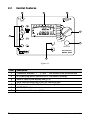
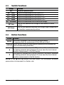
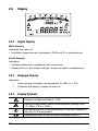
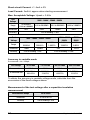
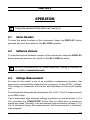
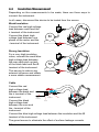
MEGOHMMETER ENGLISH User Manual 6505 Statement of Compliance Chauvin Arnoux®, Inc. d.b.a. AEMC® Instruments certifies that this instrument has been calibrated using standards and instruments traceable to international standards. We guarantee that at the time of shipping your instrument has met its published specifications. An NIST traceable certificate may be requested at the time of purchase, or obtained by returning the instrument to our repair and calibration facility, for a nominal charge. The recommended calibration interval for this instrument is 12 months and begins on the date of receipt by the customer. For recalibration, please use our calibration services. Refer to our repair and calibration section at www.aemc.com. Serial #: _ ________________________________ Catalog #: 2130.18 Model #: 6505 Please fill in the appropriate date as indicated: Date Received: __________________________________ Date Calibration Due: ________________________ Chauvin Arnoux®, Inc. d.b.a AEMC® Instruments www.aemc.com Table of Contents INTRODUCTION...................................................................................... 4 1.1 1.2 1.3 1.4 Symbols.....................................................................................4 Definition of Measurement Categories......................................5 Receiving Your Shipment...........................................................5 Ordering Information..................................................................6 1.4.1 Accessories and Replacement Parts.............................6 PRODUCT FEATURES.............................................................................. 7 2.1 2.2 2.3 2.4 2.5 Description.................................................................................7 Control Features........................................................................8 Switch Functions........................................................................9 Button Functions........................................................................9 Display.....................................................................................10 2.5.1 Digital Display..............................................................10 2.5.2 Bargraph Display.........................................................10 2.5.3 Display Symbols..........................................................10 SPECIFICATIONS.................................................................................. 11 3.1 3.2 3.3 3.4 3.5 3.6 3.7 3.8 3.9 Reference Conditions.............................................................. 11 Voltage..................................................................................... 11 Insulation Resistance............................................................... 11 Capacitance.............................................................................14 Power Supply...........................................................................15 Environmental Specifications...................................................15 Mechanical Specifications.......................................................16 Safety Specifications...............................................................16 Variations in Operating Range.................................................16 OPERATION.......................................................................................... 17 4.1 4.2 4.3 4.4 Serial Number..........................................................................17 Software Version......................................................................17 Voltage Measurement..............................................................17 Insulation Measurement .........................................................18 4.5 PI Measurement......................................................................20 4.5.1 Adjustments of the PI...................................................21 4.6 Adjustment of the Variable Test Voltage..................................22 4.7 Adjustment of the Maximum Test Voltage................................22 4.8 Error Messages.......................................................................23 MAINTENANCE.................................................................................... 24 5.1 Recharging the Battery............................................................24 5.2 Fuse Replacement...................................................................25 5.3 Cleaning...................................................................................25 5.4 Storage....................................................................................25 Repair and Calibration............................................................................26 Technical and Sales Assistance.............................................................26 Limited Warranty....................................................................................27 Warranty Repairs....................................................................................27 CHAPTER 1 INTRODUCTION WARNING This instrument is protected against accidental voltages of not more than 1000V with respect to earth in measurement Category III. The protection provided by the instrument may be compromised if it is used in a way not specified by the manufacturer. • Make no measurements on conductors likely to be connected to a live source. • Comply with the rated voltage and maximum current and the measurement category. • Never exceed the protection limits indicated in the specifications. • Comply with the conditions for use: temperature, humidity, altitude, degree of pollution and place of use. • Do not use the instrument or its accessories if they seem damaged. • Use only the accessories delivered with the unit, compliant with safety standards (IEC 61010-2-031). • Respect the value and type of the fuse (see § 5.2) to avoid damaging the instrument and voiding the warranty. • Set the switch to OFF when the instrument is not in use. • Repairs and metrological verifications must be carried out by approved, qualified personnel. • Wear the appropriate protective gear (insulated boots & gloves). 1.1 Symbols Signifies that the instrument is protected by double or reinforced insulation. CAUTION - Risk of Danger! Indicates a WARNING and that the operator must refer to the user manual for instructions before operating the instrument in all cases where this symbol is marked. Risk of electric shock. The voltage at the parts marked with this symbol may be dangerous. 4 Megohmmeter Model 6505 Ground/Earth Important instructions to read and understand completely Important information to acknowledge Battery Fuse USB socket The CE marking guarantees conformity with European directives and with regulations covering EMC. The trashcan with a line through it means that in the European Union, the product must undergo selective disposal for the recycling of electric and electronic material, in compliance with Directive WEEE 2002/96/EC. 1.2 Definition of Measurement Categories CAT I: For measurements on circuits not directly connected to the AC supply wall outlet such as protected secondaries, signal level, and limited energy circuits. CAT II: For measurements performed on circuits directly connected to the electrical distribution system. Examples are measurements on household appliances or portable tools. CAT III: For measurements performed in the building installation at the distribution level such as on hardwired equipment in fixed installation and circuit breakers. CAT IV: For measurements performed at the primary electrical supply (<1000V) such as on primary overcurrent protection devices, ripple control units, or meters. 1.3 Receiving Your Shipment Upon receiving your shipment, make sure that the contents are consistent with the packing list. Notify your distributor of any missing items. If the equipment appears to be damaged, file a claim immediately with the carrier and notify your distributor at once, giving a detailed description of any damage. Save the damaged packing container to substantiate your claim. Megohmmeter Model 6505 5 1.4 Ordering Information Megohmmeter Model 6505................................................ Cat. #2130.18 Includes small classic tool bag, set of 3 color-coded 6 ft leads [5000V] (red, blue, black), set of 3 color-coded alligator clips 600V CAT IV (red, blue, black), one blue jumper lead for use with guard terminal, fuse 0.1A 380V, rechargeable battery pack (installed), US 115V power cord and user manual. 1.4.1 Accessories and Replacement Parts Replacement - 1 ft jumper lead............................................ Cat. #2119.78 Leads - Set of 3 color-coded 10 ft safety leads [5000V] (red, blue, black) and set of 3 alligator clips 600V CAT IV............................... Cat. #2119.76 Replacement - Set of 3 color-coded 6 ft safety leads [5000V] (red, blue, black)................................................................... Cat. #2119.77 Fuse, set of 5, 0.1A, 380V, 5 x 20, .10kA............................. Cat. #2119.84 Replacement - Small classic tool bag.................................. Cat. #2133.72 Replacement - Safety alligator (red) 600V CAT IV............... Cat. #2140.52 Replacement - Safety alligator (black) 600V CAT IV............ Cat. #2140.53 Replacement - Safety alligator (blue) 600V CAT IV............. Cat. #2140.54 Replacement - 9.6V rechargeable NiMH battery.................. Cat. #2960.21 Replacement - Power Cord 115V US Plug........................... Cat. #5000.14 Order Accessories and Replacement Parts Directly Online Check our Storefront at www.aemc.com/store for availability 6 Megohmmeter Model 6505 CHAPTER 2 PRODUCT FEATURES 2.1 Description The Megohmmeter Model 6505 is a portable instrument housed in a rugged field case and operates on either battery or line power. It performs voltage, insulation, and capacitance measurements. This instrument contributes to the safety of electrical installations and equipment. Features include automatic calculation and presentation of the Dielectric Absorption Ratio (DAR) and Polarization Index (PI). The Model 6505 displays the test voltage, insulation resistance and the leakage current during the test. Capacitance of the sample and discharge voltage present at the test leads is displayed at the conclusion of the test. This Model 6505 is designed with the highest level of built-in safety features. This meter incorporates test inhibit capabilities which will not allow test voltages to be generated if a live sample is detected. The test terminals are recessed to ensure operating safety. Features: • Test voltage combination of 500V, 1000V, 2500V and 5000V • Insulation measurements from 30kΩ to 10TΩ • Adjustable and programmable test voltage (40 to 5100V) • Automatic calculation of DAR and PI values • Direct measurement and display of Capacitance and Leakage Current • Display of resistance, test voltage and run time • Programmable test run times and PI ratio times • Automatic test inhibition if live sample (>25) • Automatic discharge and display of discharge voltage • Large dual-display with time, voltage and measurements shown • Rugged dual wall weatherproof field case • Designed and built to IEC safety standards • EN 61010-1, 1000V CAT III Megohmmeter Model 6505 7 2.2 Control Features 2 4 3 110 - 230V 50/60 Hz 20 VA max CALIBRATION SET V LOCK SET V VAR MΩ 50-5000V 5 MΩ-5000V FF 0.1A 380V - 10kA 5x20mm MΩ-2500V 1 MΩ-1000V G MΩ- 500V DISPLAY OFF 6 START/STOP (>2s:DAR-PI ) 1000V CAT III ( 2500V ) MEGOHMMETER MODEL 6505 7 Figure 2-1 Item 1 8 Description Connection terminals “+”, “G” and “-” and access to the protective fuse 2 AC power plug (direct operation on AC and battery recharge) 3 Back-lit liquid crystal display (see § 2.5) 4 Serial interface male plug (9-pin) for calibration only 5 Rotary selector switch with 8 positions (see § 2.3) 6 START/STOP button 7 Two function buttons (see § 2.4) Megohmmeter Model 6505 2.3 Switch Functions Range OFF Function Instrument powered down MΩ - 500V Insulation measurement at 500V, up to 2TΩ MΩ - 1000V Insulation measurement at 1000V, up to 4TΩ MΩ - 2500V Insulation measurement at 2500V, up to 10TΩ MΩ - 5000V Insulation measurement at 5000V, up to 10TΩ MΩ - 50-5000V Insulation measurement with variable test voltage SET V VAR Sets the user definable test voltage for the variable 50-5000V position SET V LOCK Sets the user definable maximum test voltage output irrespective of the insulation measurement positions 2.4 Button Functions Button Function ON/OFF This button is pressed to start then stop the measurement. A long press starts the measurement of the DAR and of the PI. DISPLAY Before, during or after the measurement, pressing this key displays the various measurement parameters. ▲ This function is available only in the SET positions of the switch. Increases the flashing parameter being displayed. To move about the list of interval insulation measurements, in the R(t) function. ▼ This function is available only in the SET positions of the switch. Decreases the flashing parameter being displayed. To move about the list of interval insulation measurements in the R(t) function. NOTE: If the and buttons are held down, the movement between parameters is increased to a faster rate. Megohmmeter Model 6505 9 2.5 Display 2.5.1 Digital Display Main Display Indicates the value of: • Insulation measurement (resistance, DAR and PI or capacitance). Small Display Indicates: • Voltage measured or applied by the instrument. • Elapsed time or the output voltage, during insulation measurement. 2.5.2 Bargraph Display Indicates: • Active during insulation measurement (0.1MΩ to 1TΩ). • Indicates the battery charge at start-up. 2.5.3 Display Symbols Dangerous voltage generated; V >120V. External voltage present, symbol is activated after pressing START, if V >25VAC ± 3V or > 35VDC. Indicates the duration of the measurement, or the time remaining in the case of a PI measurement. Indicates the battery is low and must be recharged (see § 5.1). 10 Megohmmeter Model 6505 CHAPTER 3 SPECIFICATIONS 3.1 Reference Conditions Influence Quantity Reference Values Temperature Relative humidity Supply voltage Frequency range Capacity in parallel on resistor Electrical field Magnetic field 3.2 23 ± 3°C 45 to 55% RH 9 to 12V DC and 15.3 to 65Hz 0µF nil < 40 A/m Voltage Measurement Range 1.0 to 99.9V Frequency Range* 100 to 999V 1000 to 2500V 2501 to 5100V DC and 15 to 500Hz Resolution 0.1V Accuracy 1% of Reading ± 5cts Input Impedance 1V DC 2V 2V 1% of Reading ± 3cts 750kΩ at 3MΩ depending on measure voltage *Over 500Hz, the small display indicates “- - - -” and the main display gives only an assessment of the peak value of the measured voltage. 3.3 Insulation Resistance Method: Voltage-current method according to EN 61557-2 (ed. 02/97) Nominal Output Voltage: 500, 1000, 2500, 5000VDC (or adjustable from 40 to 5100V) No Adjustment in Variable Mode: 10V from 40 to 1000V 100V from 1000 to 5100V Nominal Current: >1mADC Megohmmeter Model 6505 11 Short-circuit Current: <1.6mA ± 5% Load Current: 3mADC approx when starting measurement Max. Acceptable Voltage: Upeak = 0.4Un Test Voltage 500V - 1000V - 2500V - 5000V Range 10 to 999kΩ 1.000 to 3.999MΩ 4.00 to 39.99MΩ 40.0 to 399.9MΩ 0.400 to 3.999GΩ Resolution 1kΩ 10kΩ 100kΩ 1MΩ Accuracy ±5% of Reading + 3cts Test Voltage 500V - 1000V - 2500V - 5000V Range 4.00 to 39.99GΩ 40.0 to 399.9GΩ Resolution 10MΩ 100MΩ Accuracy ±5% of Reading + 3cts 1000V - 2500V 5000V 2500V 5000V 2.000 to 3.999TΩ 4.00 to 9.99TΩ 0.400 to 1.999TΩ 1GΩ 10GΩ ±15% of Reading + 10cts Accuracy in variable mode R measured = Un / 250pA Test voltage 40 to 160V 170 to 510V 520 to 1500V 1600 to 5100V R measured min 10kΩ 10kΩ 10kΩ 10kΩ R measured max 160.0GΩ to 640.0GΩ 640.0GΩ to 2.040TΩ 2.080TΩ to 6.000TΩ 6.400TΩ to 10.00TΩ To obtain the accuracy in variable voltage mode, calculate from the accuracies of the fixed voltages above. Measurement of the test voltage after a capacitive insulation measurement 12 Measurement Range 25 to 5000V Resolution 0.2% Un or 1ct Accuracy 5% of Reading ± 3cts Megohmmeter Model 6505 Calculation of terms DAR and PI Specified Range 0.02 - 50.00 Resolution 0.01 Accuracy 5% of Reading ± 1ct Typical change curve for test voltages according to load: Range 500V V 600 500 400 300 200 100 0 0.01 0.1 1 MΩ Range 1000V V 1200 1000 800 600 400 200 0 0.1 Megohmmeter Model 6505 1 MΩ 13 Range 2500V V 3000 2500 2000 1500 1000 500 0 0.1 1 10 MΩ Range 5000V V 6000 5000 4000 3000 2000 1000 0 3.4 0.1 1 10 MΩ Capacitance This measurement is made at the end of each insulation measurement, while the circuit is being discharged. 14 Measurement Range 0.001 to 9.999 µF 10.00 to 49.99 µF Resolution 1 nF 10 nF Accuracy 10% of Reading ± 1ct 10% Megohmmeter Model 6505 3.5 Power Supply • Rechargeable battery NiMh (8 x 1.2V / 3.5Ah) • Line Voltage: 85 to 256V / 50-60Hz Minimum Battery Charge Life (per NF EN 61557-2) Test Voltage Nominal Charge Number of Measurements 5s on nominal charge (with 25s pause between each measurement) 500V 500kΩ 6500 1000V 1MΩ 5500 2500V 2.5MΩ 4000 5000V 5MΩ 1500 Average Battery Life: The operating time will be 15 days or 3 weeks, based upon a 10 minute long PI measurement. Recharge Time: Charging must be done between 20 and 30°C 6 hours for 100% capacity (10 hours if the battery is completely drained) 0.5 hours for 10% capacity (charge life: 2 days approximately) NOTE: It is possible to recharge the batteries while performing insulation measurements provided that the values measured are higher than 20MΩ. In this case, the recharging time is higher than 6 hours and depends on the frequency of the measurements. 3.6 Environmental Specifications Operating Range: 14° to 104°F (-10° to 40°C) during recharging of batteries 14° to 131°F (-10° to 55°C) during measurement 10 to 80% RH Storage: -40 to 158°F (-40 to 70°C); 10 to 90% RH Altitude: <2000m Use indoors or outdoors Megohmmeter Model 6505 15 3.7 Mechanical Specifications Case Dimensions: 10.63 x 9.84 x 7.09" (270 x 250 x 180mm) Weight: 9.5 lbs (4.3kg) approx. Mechanical Protection IP 53 per NF EN 60529 (Ed. 92) IK 04 per NF EN 50102 (Ed. 95) 3.8 Safety Specifications Electrical safety according to EN 61010-1 (Ed. 2 for 2001), EN 61557 (Ed. 2005) 1000V CAT III 2500V CAT I Pollution Degree 2 Electromagnetic Compatibility: NF EN 61326-1 (Ed. 97) + A1, industrial environment category 3.9 Variations in Operating Range Influence Influential Quantity Range of Influence Quantity Influenced* Typical Max. Battery Voltage 9V to 12V V MΩ <1ct <1ct 2cts 3cts Temperature -10° to +55°C V MΩ 0.15% R/10°C 0.20% R/10°C 0.3% R/10°C ± 1ct 1% R/10°C ± 1ct Humidity 20 to 80% RH V MΩ (10kΩ to 40GΩ) MΩ (40GΩ to 10TΩ) 0.2% R 0.2% R 3% R 1% R ± 2cts 1% R ± 5cts 15% R ± 5cts Frequency 15 to 500Hz V 0.3% R 0.5% R ± 1ct AC voltage superimposed on test voltage 0% to 20% Vn MΩ 0.1% R / % Vn 0.5% R / % Vn ± 5cts *The terms DAR, PI and the capacity and current leak measurements are included in the quantity “M Ω”. 16 Megohmmeter Model 6505 CHAPTER 4 OPERATION Charge the instrument fully before use (see § 5.1) 4.1 Serial Number To view the serial number of the instrument, keep the DISPLAY button pressed and turn the switch to the MW-500V position. 4.2 Software Version To view the internal software version of the instrument, keep the DISPLAY button pressed and turn the switch to the MW-1000V position. Technical documentation on Ground Resistance Testing is available on our website at www.aemc.com. 4.3 Voltage Measurement As soon as the switch is set to an insulation measurement position, the instrument automatically measures the presence of any AC/DC voltage. This voltage is measured at all times and indicated on the small display unit. The instrument automatically determines AC or DC. The AC measurement is an RMS value. If an excessively high external voltage is present on the terminals (> 0.4 Un), pressing the START/STOP button has no effect and no measurements are made. Similarly, if an excessively high erroneous voltage (> 0.4 Un) is detected during the measurement, the measurement is automatically stopped. Megohmmeter Model 6505 17 4.4 Insulation Measurement Depending on the measurements to be made, there are three ways to connect the instrument. In all cases, disconnect the device to be tested from the source. Weak Insulation Connect the red high-voltage lead between earth and the + terminal of the instrument. Connect the black highvoltage lead between one phase of the motor and the - terminal of the instrument. M - M - + Strong Insulation For a very high insulation value, connect the small blue high-voltage lead between the rear earth pick-up jack of the black lead and the G terminal of the instrument. + G This serves to reduce any external influence and obtain a more stable measurement. Cable Connect the red high-voltage lead between the braid and the + terminal of the instrument. Connect the black high-voltage lead between the core and the - terminal of the instrument. G Exterior Insulation Insulation Core + - Braid Connect the blue high-voltage lead between the insulation and the G terminal of the instrument. The guard serves to eliminate the effect of surface leakage currents. 18 Megohmmeter Model 6505 Once the connections have been made, choose the desired test voltage on the rotary switch. When powered up, the instrument displays the following: • Condition of the battery • Test voltage • Voltage present on the object to be tested • Press the START/STOP button to start the measurement. • During measurements, the instrument will beep every 10 seconds to alert the user that a high voltage is present. • Press the START/STOP button again to stop the measurement. The instrument continues to measure external voltages but the test result remains displayed on the main display unit. To ensure your safety, the instrument will automatically discharge the circuit under test, allow for the voltage displayed to fall back below 25V before disconnecting the leads. Press the DISPLAY button to display: Before the measurement (2 presses) • voltage present on the device to be tested • test voltage • surface leakage current During the measurement (2 presses) • • • • After the measurement (5 presses) Megohmmeter Model 6505 test voltage instantaneous insulation resistance value duration of the measurement current flowing in the resistance being measured • voltage present on the device tested • insulation resistance value just before the measurement was stopped • duration of the measurement • test voltage generated during the measurement • current that flowed in the resistance measured • surface leakage current • capacitance 19 4.5 PI Measurement • Set the switch to one of the insulation measurement positions. MΩ-1000V • Start the measurement by a long press (>2s) on the START/STOP button. The long press is acknowledged by an audible beep. MΩ-1000V • The measurement starts the default duration of 10 min. A countdown displays the time remaining. The measurement stops automatically. Press the DISPLAY button to display: Before the measurement (2 presses) • voltage present on the device to be tested • test voltage • leakage current present During the measurement (4 presses) • • • • • • measurement time remaining instantaneous insulation resistance value test voltage current flowing in the resistance being measured value of PI (available at the end of 10 minutes) value of DAR (available at the end of one minute) After the measurement (6 presses) • • • • test voltage generated during the measurement PI and DAR duration of the measurement insulation resistance value just before the measurement was stopped current that flowed in the resistance measured voltage present on the device being tested capacitance surface leakage current • • • • The values of PI and DAR are calculated as follows: PI = R 10 min / R 1 min (2 values to be recorded during a measurement lasting 10 min)* DAR = R 1 min / R 30 sec (2 values to be recorded during a measurement lasting 1 min) *For the calculation of the PI, the times of 1 and 10 minutes can be modified by the user, if required, for a particular application. See § 4.5.1. 20 Megohmmeter Model 6505 They are especially useful for monitoring the ageing of the insulation of revolving machines or of very long cables. On items of this type, the measurement is initially perturbed by spurious currents (capacitive charging current, dielectric absorption current) that gradually cancel out. To measure the leakage current representative of the insulation accurately, it is therefore necessary to make measurements of long duration. The quality of the insulation is a function of the results found. DAR < 1.25 < 1.6 > 1.6 PI <1 <2 <4 >4 Condition of the Insulation Inadequate or even dangerous Good Excellent 4.5.1 Adjustments of the PI It is possible to modify the PI times to meet specific needs. Reminder: PI = R 10 min / R 1 min The first PI time is 1 min. It can be set to values from 30 sec to 30 min in 30 sec steps. • Press and hold the DISPLAY button and turn the rotary switch to the SET V VAR position. Hold the DISPLAY button until PI_1 appears in the display. • You can change the first PI time (PI_1) using the ▲ and ▼ buttons. • To save changes simply, turn the switch. • The second PI time (PI_2) is 10 min. It can be set to values from PI_1 up to 59 min in 1 min steps. • Press and hold the DISPLAY button and turn the rotary switch to the SET V LOCK position. • You can modify the second PI time using the ▲ and ▼ buttons. • To save changes simply, turn the switch. Megohmmeter Model 6505 21 4.6 SET V VAR Adjustment of the Variable Test Voltage SET V VAR This function makes it possible to use test voltages other than the 4 preset values of 500, 1000, 2500 and 5000. • Set the switch to SET V VAR. • The test voltage flashes. • Change the test voltage using the ▲ and ▼ buttons. MΩ 50-5000V MΩ 50-5000V • Set the switch to MW 50-5000V to make the measurement. • This value is retained in a non-volatile memory. 4.7 Adjustment of the Maximum Test Voltage The user can set a maximum generated voltage to prevent any accidental over-voltage tests being conducted in error. SET V LOCK SET V LOCK • Set the switch to SET V LOCK. • The maximum test voltage flashes and can be adjusted using the ▲ and ▼ buttons. • Turn the switch to an insulation measurement setting to make measurements. • The maximum test voltage value is retained in a non-volatile memory. It will be displayed for a few seconds on selection of an affected range. (e.g. if the maximum voltage is 750V, it will be applied and displayed on all switch settings from 1000V up). 22 Megohmmeter Model 6505 4.8 0.1M Error Messages 1M 10M 100M 1G 10G 100G 1T • Check your connections. The + and - terminal of the instrument may be short-circuited. V 0.1M 1M 10M 100M 1G 10G V • The insulation resistance is too low. 100G 1T • The insulation resistance is outside the measurement range. • Check your connections. One of the terminals of the instrument may be disconnected or the value measured is > 4TΩ. • The voltage present on the terminals is greater than 25VAC or 35Vpeak. VAC VAC • The instrument alerts you but does not prevent making the measurement. • The voltage present on the terminals is too high for a measurement to be made: peak V > 0.4 Un The test voltage, Un, is indicated by the setting of the switch. • Eliminate the voltage and restart the measurement. • Indicates that the protective fuse of the G terminal is defective. • Replace the fuse as indicated in § 5.2. Megohmmeter Model 6505 23 CHAPTER 5 MAINTENANCE Use only factory specified replacement parts. AEMC® will not be held responsible for any accident, incident, or malfunction following a repair done other than by its service center or by an approved repair center. 5.1 Recharging the Battery If the symbol displays, the battery needs to be recharged. Connect the instrument to the 115VAC power cord via the connector (charging starts automatically). • bAt on the small display and chrG on the main display signifies fast charging in progress. • bAt on the small display and chrG flashing on the main display signifies slow charging. • bAt on the small display and FULL on the main display signifies that charging is complete. If the instrument is started up and the battery voltage is >8V, then the normal use of the device is permitted. NOTE: The battery should only be changed by an authorized repair facility recognized by AEMC® Instruments. 24 Megohmmeter Model 6505 5.2 Fuse Replacement If FUSE -G- flashes on the display, the fuse must be replaced, taking all the necessary precautions when opening up the instrument. Make sure that none of the terminals are connected and that the selector switch is set to OFF. • The fuse is located on the left side of the faceplate, indicated by the symbol. • Using a coin or a flathead screwdriver, unscrew the fuse holder and remove the fuse. • Only replace with the type of fuse specified on the label inside the unit’s cover: 0.1A - Fast Acting - 380V, 5x20mm, 10kA NOTE: If after changing the fuse the display still indicates FUSE -G-, the instrument must be returned to the factory for servicing. 5.3 Cleaning Disconnect the instrument from any source of electricity. Use a soft cloth lightly dampened with soapy water. Rinse with a damp cloth and then dry with a dry cloth. Do not use alcohol, solvents or hydrocarbons. 5.4 Storage If the instrument is not used for an extended period of time, it is recommended to charge the instrument every two or three months. Megohmmeter Model 6505 25 Repair and Calibration To ensure that your instrument meets factory specifications, we recommend that it be scheduled back to our factory Service Center at one-year intervals for recalibration, or as required by other standards or internal procedures. For instrument repair and calibration: You must contact our Service Center for a Customer Service Authorization Number (CSA#). This will ensure that when your instrument arrives, it will be tracked and processed promptly. Please write the CSA# on the outside of the shipping container. If the instrument is returned for calibration, we need to know if you want a standard calibration, or a calibration traceable to N.I.S.T. (Includes calibration certificate plus recorded calibration data). Ship To: Chauvin Arnoux®, Inc. d.b.a. AEMC® Instruments 15 Faraday Drive Dover, NH 03820 USA Phone:(800) 945-2362 (Ext. 360) (603) 749-6434 (Ext. 360) Fax: (603) 742-2346 or (603) 749-6309 E-mail:[email protected] (Or contact your authorized distributor) Costs for repair, standard calibration, and calibration traceable to N.I.S.T. are available. NOTE: You must obtain a CSA# before returning any instrument. Technical and Sales Assistance If you are experiencing any technical problems, or require any assistance with the proper operation or application of your instrument, please call, mail, fax or e-mail our technical support team: Chauvin Arnoux®, Inc. d.b.a. AEMC® Instruments 200 Foxborough Boulevard Foxborough, MA 02035 USA Phone:(800) 343-1391 (508) 698-2115 Fax: (508) 698-2118 E-mail:[email protected] www.aemc.com NOTE: Do not ship instruments to our Foxborough, MA address. 26 Megohmmeter Model 6505 Limited Warranty The Megohmmeter Model 6505 is warranted to the owner for a period of one year from the date of original purchase against defects in manufacture. This limited warranty is given by AEMC® Instruments, not by the distributor from whom it was purchased. This warranty is void if the unit has been tampered with, abused or if the defect is related to service not performed by AEMC® Instruments. For full and detailed warranty coverage, please read the Warranty Coverage Information, which is attached to the Warranty Registration Card (if enclosed) or is available at www.aemc.com. Please keep the Warranty Coverage Information with your records. What AEMC® Instruments will do: If a malfunction occurs within the one-year period, you may return the instrument to us for repair, provided we have your warranty registration information on file or a proof of purchase. AEMC® Instruments will, at its option, repair or replace the faulty material. REGISTER ONLINE AT: www.aemc.com Warranty Repairs What you must do to return an Instrument for Warranty Repair: First, request a Customer Service Authorization Number (CSA#) by phone or by fax from our Service Department (see address below), then return the instrument along with the signed CSA Form. Please write the CSA# on the outside of the shipping container. Return the instrument, postage or shipment pre-paid to: Ship To: Chauvin Arnoux®, Inc. d.b.a. AEMC® Instruments 15 Faraday Drive • Dover, NH 03820 USA Phone:(800) 945-2362 (Ext. 360) (603) 749-6434 (Ext. 360) Fax: (603) 742-2346 or (603) 749-6309 E-mail:[email protected] Caution: To protect yourself against in-transit loss, we recommend you insure your returned material. NOTE: You must obtain a CSA# before returning any instrument. Megohmmeter Model 6505 27 Notes: 28 Megohmmeter Model 6505 07/09 99-MAN 100339 v2 Chauvin Arnoux®, Inc. d.b.a. AEMC® Instruments 15 Faraday Drive • Dover, NH 03820 USA • Phone: (603) 749-6434 • Fax: (603) 742-2346 www.aemc.com