1
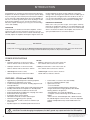
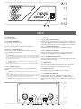
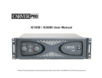
ZR1000 & ZR1600
Power Amplifiers
USER MANUAL
ZR1000 & ZR1600
Power Amplifiers
CAUTION
RISK OF ELECTRIC SHOCK
DO NOT OPEN
CAUTION: TO REDUCE THE RISK OF ELECTRIC SHOCK, DO NOT REMOVE
THE COVER. NO USER SERVICEABLE PARTS INSIDE. REFER SERVICING TO
QUALIFIED PERSONNEL!
EXPLANATION OF
SAFETY SYMBOLS
The exclamation point within an equilateral triangle is intended to alert the user of the presence of
important operating and maintenance (servicing) instructions in the literature accompanying the
appliance.
The lightning flash with the arrowhead symbol within an equilateral triangle is intended to alert the
user to the presence of uninsulated “dangerous voltage” within the products’ enclosure that may
be of sufficient magnitude to constitute a risk of electric shock to persons.
IMPORTANT SAFETY INSTRUCTIONS
1)
2)
3)
4)
5)
6)
7)
8)
9)
10)
11)
12)
13)
Read these instructions.
Keep these instructions.
Heed all warnings.
Follow all instructions.
Do not use this apparatus in or near water.
Clean only with a dry cloth.
Do not block any ventilation openings. Install in accordance with the manufacturer’s instructions.
Do not install near any heat sources such as radiators, heat registers, stoves, or other apparatus that produce heat.
Do not defeat the safety purpose of the polarized or grounding-type plug. A polarized plug has two blades with one wider than the
other. A grounding- type plug has two blades and a third grounding prong. The wide blade or the third prong is provided for your
safety. If the provided plug does not fit into your outlet, consult an electrician for replacement of the obsolete outlet.
Protect the power cord from being walked on or pinched, particularly at plugs, convenience receptacles, and the point where they exit
from the apparatus.
Only use attachments/accessories specified by the manufacturer.
Unplug this apparatus during lightning storms or when unused for long periods of time.
Refer all servicing to qualified service personnel. Servicing is required when the apparatus has been damaged in any way, such as
power supply cord or plug is damaged, liquid has been spilled or objects have fallen into the apparatus, the apparatus has been
exposed to rain or moisture, does not operate normally or has been dropped.
TO REDUCE THE RISK OF FIRE OR ELECTRIC SHOCK, DO NOT EXPOSE THIS APPARATUS TO RAIN OR MOISTURE.
TO PREVENT ELECTRIC SHOCK DO NOT REMOVE TOP OR BOTTOM COVERS.
NO USER SERVICEABLE PARTS INSIDE. REFER SERVICING TO QUALIFIED SERVICE PERSONNEL.
FCC COMPLIANCE NOTICE: This device complies with part 15 of the FCC rules. Operation is subject to the following two conditions: (1)
This device may not cause harmful interference, and (2) this device must accept any interference received, including interference that
may cause undesired operation.
CAUTION: Changes or modifications not expressly approved by the party responsible for compliance could void the user’s authority to
operate the equipment.
NOTE: This equipment has been tested and found to comply with the limits for a Class B digital device, pursuant to part 15 of the
FCC Rules. These limits are designed to provide reasonable protection against harmful interference in a residential installation. This
equipment generates, uses, and can radiate radio frequency energy and, if not installed and used in accordance with the instruction
manual, may cause harmful interference to radio communications. However, there is no guarantee that interference will not occur in a
particular installation. If this equipment does cause harmful interference to radio or television reception, which can be determined by
turning the equipment off and on, the user is encouraged to try to correct the interference by one or more of the following measures:
• Reorient or relocate the receiving antenna.
• Increase the separation between the equipment and receiver.
• Connect the equipment into an outlet on a circuit different from that to which the receiver is connected.
IMPORTANT: ZR Series amplifiers require Class 2 output wiring.
MAGNETIC FIELD
CAUTION! Do not locate sensitive high-gain equipment such as preamplifiers or tape decks directly above or below the unit. Because
this amplifier has a high power density, it has a strong magnetic field, which can induce hum into unshielded devices that are located
nearby. The field is strongest just above and below the unit. If an equipment rack is used, we recommend locating the amplifier(s) in
the bottom of the rack and the preamplifier or other sensitive equipment at the top.
2
TABLE OF CONTENTS
SAFETY INSTRUCTIONS . . . . . . . . . . . . . . . . . . . . . . . . . . . . . . . . . . . . . . . . . . . . . . . . . . . . . . . . . . . . . . . .2
Magnetic Field Warning . . . . . . . . . . . . . . . . . . . . . . . . . . . . . . . . . . . . . . . . . . . . . . . . . . . . . . . . . . .2
FCC Compliance Notice . . . . . . . . . . . . . . . . . . . . . . . . . . . . . . . . . . . . . . . . . . . . . . . . . . . . . . . . . .2
INTRODUCTION . . . . . . . . . . . . . . . . . . . . . . . . . . . . . . . . . . . . . . . . . . . . . . . . . . . . . . . . . . . . . . . . . . . . . . .4
Unpacking . . . . . . . . . . . . . . . . . . . . . . . . . . . . . . . . . . . . . . . . . . . . . . . . . . . . . . . . . . . . . . . . . . . . .4
Important Paperwork . . . . . . . . . . . . . . . . . . . . . . . . . . . . . . . . . . . . . . . . . . . . . . . . . . . . . . . . . . . . .4
POWER SPECIFICATIONS . . . . . . . . . . . . . . . . . . . . . . . . . . . . . . . . . . . . . . . . . . . . . . . . . . . . . . . . . . . . . . .4
FEATURES . . . . . . . . . . . . . . . . . . . . . . . . . . . . . . . . . . . . . . . . . . . . . . . . . . . . . . . . . . . . . . . . . . . . . . . . . . . .4
SPECIFICATIONS . . . . . . . . . . . . . . . . . . . . . . . . . . . . . . . . . . . . . . . . . . . . . . . . . . . . . . . . . . . . . . . . . . . . . .5
EXTERNAL CHASSIS DIMENSIONS . . . . . . . . . . . . . . . . . . . . . . . . . . . . . . . . . . . . . . . . . . . . . . . . . . . . . . .5
EXTERNAL CONTROLS, CONNECTORS, AND STATUS INDICATORS . . . . . . . . . . . . . . . . . . . . . . . . . . . .6
Front Panel. . . . . . . . . . . . . . . . . . . . . . . . . . . . . . . . . . . . . . . . . . . . . . . . . . . . . . . . . . . . . . . . . . . . .6
Rear Panel . . . . . . . . . . . . . . . . . . . . . . . . . . . . . . . . . . . . . . . . . . . . . . . . . . . . . . . . . . . . . . . . . . . . .7
INTERNAL JUMPER SETTINGS . . . . . . . . . . . . . . . . . . . . . . . . . . . . . . . . . . . . . . . . . . . . . . . . . . . . . . . . . . .8
Input Polarity . . . . . . . . . . . . . . . . . . . . . . . . . . . . . . . . . . . . . . . . . . . . . . . . . . . . . . . . . . . . . . . . . . .8
Input Sensitivity . . . . . . . . . . . . . . . . . . . . . . . . . . . . . . . . . . . . . . . . . . . . . . . . . . . . . . . . . . . . . . . . .8
INSTALLATION AND CONNECTIONS. . . . . . . . . . . . . . . . . . . . . . . . . . . . . . . . . . . . . . . . . . . . . . . . . . . . . . .9
Mounting . . . . . . . . . . . . . . . . . . . . . . . . . . . . . . . . . . . . . . . . . . . . . . . . . . . . . . . . . . . . . . . . . . . . . .9
Temperature/Humidity Considerations . . . . . . . . . . . . . . . . . . . . . . . . . . . . . . . . . . . . . . . . . . . . . . .9
AC Power. . . . . . . . . . . . . . . . . . . . . . . . . . . . . . . . . . . . . . . . . . . . . . . . . . . . . . . . . . . . . . . . . . . . . .9
Input Configuration . . . . . . . . . . . . . . . . . . . . . . . . . . . . . . . . . . . . . . . . . . . . . . . . . . . . . . . . . . . . . .9
Balanced and Unbalanced Connections . . . . . . . . . . . . . . . . . . . . . . . . . . . . . . . . . . . . . . . . . . . . . .9
Output Configuration . . . . . . . . . . . . . . . . . . . . . . . . . . . . . . . . . . . . . . . . . . . . . . . . . . . . . . . . . . . .10
Replacing Input Modules. . . . . . . . . . . . . . . . . . . . . . . . . . . . . . . . . . . . . . . . . . . . . . . . . . . . . . . . .10
Sequencing . . . . . . . . . . . . . . . . . . . . . . . . . . . . . . . . . . . . . . . . . . . . . . . . . . . . . . . . . . . . . . . . . . .11
WARRANTY INFORMATION . . . . . . . . . . . . . . . . . . . . . . . . . . . . . . . . . . . . . . . . . . . . . . . . . . . . . . . . . . . . .11
CARE AND SERVICE ASSISTANCE . . . . . . . . . . . . . . . . . . . . . . . . . . . . . . . . . . . . . . . . . . . . . . . . . . . . . . .11
IN CASE OF DIFFICULTY . . . . . . . . . . . . . . . . . . . . . . . . . . . . . . . . . . . . . . . . . . . . . . . . . . . . . . . . . . . . . . .12
3
INTRODUCTION
Congratulations on choosing the Carver Professional ZR Series
Amplifier! The ZR Series amplifiers not only have superior fidelity,
they are among the most efficient professional power amplifiers
on the market. By utilizing digital power processing (DPP®), our
ZR series can deliver generous power levels. By design, the ZR
Series power amplifiers are very accurate and efficient. Your
ZR Series amplifier should give you many years of outstanding
service and reliability.
UNPACKING
Inside the box you will find; one ZR Series Amplifier, one IECtype power cord, two Euro-style input connectors, four selfadhesive rubber feet, and an owner’s manual and warranty card.
Carefully unpack the amplifier and keep the original carton and
packing materials for future moving, shipment or long-term
storage. After opening the box, please check for visible signs of
damage that were not apparent from the outside of the box. If
you encounter what appears to be concealed damage, please
consult your Carver Professional Dealer before installing unit.
IMPORTANT PAPERWORK
Make sure to save your sales receipt. Your receipt is extremely
important to establish the duration of your Limited Warranty and
for insurance purposes. Next, make a note of the serial number,
which is located on the back of the amplifier. Record it in the
space provided below for convenient reference.
Serial Number: ________________________ Purchased at: ________________________________
Date: _____________
Finally, take a moment to fill out the Warranty Registration Card packed with the amplifier and return it to Carver Professional.
This will allow us to keep you informed about new products as they become available.
POWER SPECIFICATIONS
ZR1000
• 225W per channel into 8 ohm stereo loads,
20 Hz to 20 kHz, with less than 0.5% THD+N
ZR1600
• 300W per channel into 8 ohm stereo loads, 20
Hz to 20 kHz, with less than 0.5% THD+N
• 350W per channel into 4 ohm stereo loads,
20 Hz to 20 kHz, with less than 0.5% THD+N
• 600W per channel into 4 ohm stereo loads, 20
Hz to 20 kHz, with less than 0.5% THD+N
• 700W bridged mono into 8 ohms,
20 Hz to 20 kHz with less than 0.5% THD+N
• 1200W bridged mono into 8 ohms, 20 Hz to
20 kHz with less than 0.5% THD+N
FEATURES - ZR1000 and ZR1600
• High Efficiency Spread Spectrum Switching Amplifier
• Variable Speed, Ultra-quiet Fan Cooling
• 7 LED Level Display, Per Channel, Including Signal Present
and Clip Indicators
• 3 LED Status Display: Ready, Protect and Thermal Overload
• Standby LED Indicates the Amplifier is in Standby Mode
• Level Control Defeat Accessible From Front Panel
• Switched 40 Hz/80 Hz (12 dB/Octave Cut) High Pass Filters
• Switched Soft Knee Clip Limiters
• Soft Start In-Rush Current Limiting
• Individual Ground Lifts for Each Channel Input
• Terminals for Sequencing Power (On/Off)
• Input via Neutrik® Combo Connectors and Euro-style
Connectors
• Speaker Outputs via 3 Neutrik® Speakon® Connectors
• Power Switch, 3 Positions: ON, OFF, Standby
• AC Line Cord (Detachable IEC Type)
• Optional Accessories:
- Crossover Module
- Four Input Mixer Module with Zone Assignment
- Single and Dual Zone Paging Modules with Variable
Ducking and Zone Assignments
- Expanded Mic / Line Level Input Module
- Computer Control & Monitoring via iON Media Control
Module
- DSP Control of 28 Band Graphic EQ, 5 Band Parametric
EQ, Variable High & Low Pass Filters, Crossover, Adjustable
Limiting and Adjustable Delay via iON Media DSP Tools
Module
CAUTION: To avoid damaging the equipment, DO NOT ground any output terminal of the ZR amplifier.
4
DPP® is a registered trademark of Tripath Technology, Inc.
Speakon® is a registered trademark of Neutrik, Inc.
Neutrik® is a registered trademark of Neutrik, Inc.
SPECIFICATIONS
PERFORMANCE
THD+N:
IMD (SMPTE):
Dynamic Headroom:
Power Bandwidth:
Frequency Response:
Signal-to-Noise:
Crosstalk:
CMRR:
Slew Rate:
Sensitivity for Rated Power:
(Variable settings via jumpers)
Input Impedance:
Input Overload:
Protection:
Stability:
Duty Cycle:
<0.5% @ rated power (4 ohm), 20-20kHz, 20kHz BW
<0.15% @ rated power (4 ohm), 1kHz
<0.06% @ -10dB referenced to rated power (4 ohm), 1kHz
<0.2%, 60Hz/7kHz, 4:1, 35Vpeak @ 4 ohms
1.5dB
20-20 kHz @ 4 and 8 ohm loads
20-20kHz, +0dB/-1dB
100dB, A-Weighted, referenced to 4 ohm rated power, 22kHz BW
-70dB @1kHz referenced to rated power (4 ohm)
70dB at 1kHz
7V/Sec
0.316Vrms
0.775Vrms(Factory Preset)
1.23Vrms
2.45Vrms
50k balanced
20dBu
Thermal, Short Circuit, Over-current & Over Voltage, self-resetting
Unconditionally stable into reactive loads
Continuous operation at 1/3rd power
POWER REQUIREMENTS
Mains Voltage:
(output power rated at nominal voltage)
Maximum Consumption @ Rated Power (4 ohm), 1kHz sine wave:
ZR1000
ZR1600
100VAC (50-60Hz) ±10%
117VAC (60Hz) ±10%
234VAC (50Hz) ±10%
117VAC (60Hz)
234VAC (50Hz)
950W/10.6Arms
938W/5.35Arms
117VAC (60Hz)
234VAC (50Hz)
1.53kW/17.8Arms
1.48kW/9.09Arms
3.50
5
CLIP
0dB
- 3dB
- 6dB
- 9dB
HIGH
PASS
- 12dB
SIGNAL
40Hz
80Hz
2
3
4
READY
40Hz
80Hz
HIGH
PASS
CLIP
LIMITER
PROTECT
1
0dB
8
8
0dB
THERMAL
5
6
7
8
9 10 11 12
FRONT
1 & 10 – HIGH PASS FILTER SWITCHES
Separate switches on each channel to enable highpass filters. Highpass
filters cut off the lowest frequencies to eliminate rumble and prevent
excess speaker excursion. The filter is enabled when the switch is
pushed in.
THERMAL: Whenever the output section and/or the power transformer exceeds preset
thermal limits, the amp is disabled and will resume once it has cooled.
SIGNAL: Indicates a signal is detected at the input.
–12dB: Indicates the output has reached a level 12dB below rated power.
–9dB: Indicates the output has reached a level 9dB below rated power.
2 & 11 – HIGH PASS FILTER STATUS LEDS
Separate indicators on each channel illustrate the highpass filter status.
The LED is dark when the filter is not engaged. A Red color indicates the
cutoff is set at 40Hz, green indicates the cutoff is set at 80Hz.
–6dB: Indicates the output has reached a level 6dB below rated power.
–3dB: Indicates the output has reached a level 3dB below rated power.
0dB: Indicates the amplifier is producing full output (or slightly below, depending on load
impedance).
3 & 12 – HIGH PASS FILTER CUTOFF FREQUENCY
SELECTOR SWITCHES
Separate switches for each channel select the highpass filter cutoff
frequency. When the switches are out, the cutoff is set at 40Hz. When the
switches are in, the cutoff is set at 80Hz.
CLIP: Indicates the output signal is reaching approximately 1% distortion.
7 – CLIP LIMITER SWITCH
When the switch is “In” the clip limiter is enabled.
5 – LEVEL CONTROL DEFEAT
When the switch is in, the level controls are set to 0dB attenuation no
matter what the position of the knobs.
8 – CLIP LIMITER STATUS LED
Indicates when the clip limiter is enabled.
13 – ‘STANDBY’ LED
Indicates that the amp is in Standby mode. When in Standby mode,
the amplifier is turned “OFF”, but the AC Mains are connected and the
amplifier waits for a DC voltage at the Sequence connector on the rear of
the amp. Once a DC voltage is applied to the Sequence connector, the
amp turns “ON” and begins its start-up diagnostics and upon completion
is ready for use.
4 & 9 – LEVEL CONTROLS
Sets the amount of signal attenuation, down to a maximum of
-100dB.
6 – SIGNAL LEVEL AND DIAGNOSTIC LEDS
An array of indicators that show the operational status of the amplifier
and the signal level.
14 – POWER SWITCH
A three-position switch used to select the power operation mode. In the
center position, power is off. In the up position, power is on. In the down
position, amp is set to standby mode.
PROTECT: Whenever a very low impedance (short circuit) is detected on either of the
outputs, or an over voltage, under voltage or over current situation is detected the amplifier
will protect itself and connected loads by immediately ceasing to drive the output stage.
READY: The amplifier is operational.
SEQUENCE
SEND
RECV
BRIDGED
MONO
CH 2
CH 1
T
ZR1600 ULC 117VAC ~ 50/60Hz 1500W
CH2
MONO CH1
CH2+ Pin 1+
Pin 2+
16A-125VAC
CH2- Pin 1-
Pin 2-
CAUTION
AVIS
CH1+
Pin 1+
RISK OF ELECTRICAL SHOCK
DO NOT OPEN COVER,
AUTHORIZED PERSONNEL
ONLY.
RISQUE DE CHOC ELECTRIQUE
NE PAS OUVRIR CE CARTER,
RESERVE AU PERSONNEL
AUTORISE.
CH1MONO+
MONO-
WARNING
See user’s manual
TO REDUCE THE RISK OF FIRE OR ELECTRICAL SHOCK DO NOT
EXPOSE THIS EQUIPMENT TO RAIN OR MOISTURE
This device complies with part 15 of the FCC rules. Operation is subject to the following
conditions: (1) This device may not cause harmful interference and (2) this device must accept
any interference received, including interference which may cause undesired operation. Complies
with Canadian ICES-003 Class A specifications.
15
6
16
Pin 1Pin 1+ or 2+
Pin 1- or 2-
17
has been removed
–
CH 2
–
+
CH 1
+
BRIDGED
18
19
20
21 22
A Phoenix Gold International Company
ZR1600
STANDBY
13
14
REAR
15 – FUSE CARRIER
Holds the AC mains fuse.
black(-) post
23 & 32 – BALANCED AUDIO INPUTS
Neutrik® Combo connectors which accept male XLR, TS and TRS 1/4´´
phone plugs. By default, XLR pin 2 is hot and Tip is hot. Polarity of the
XLR can be reversed with jumper settings inside the amp. (See page 9)
16 – AC MAINS CONNECTOR
IEC type power cord attaches here.
17 – SEQUENCE CONNECTOR
Used for sequencing power to multiple amps. (See page 11)
24 & 31 - BALANCED AUDIO INPUTS
Euro-type connectors used for balanced or unbalanced signals.
18, 20 & 22 – SPEAKER OUTPUTS
A set of three 4-conductor Neutrik® Speakon® NL4 connectors to
connect the amplifier to the speakers.
25 & 30 – GROUND LIFT SWITCHES
Switches for each channel that disconnect Ground pin of the input
connectors from chassis ground. Used to eliminate ground loop
conditions that cause hum.
18 - CHANNEL TWO provides the output of channel two only, on pins 1+/1-.
20 - BRIDGED MONO uses the output of both channels to create a single channel with twice
the power. The output is provided on both pins 1+/1- and 2+/2- of the Speakon®, allowing
the use of all four conductors to lower the cable resistance. This output should only be used
when the Mono switch is enabled.
22 - CHANNEL ONE actually provides output for channel one AND channel two using a
single 4-conductor cable.
Channel one output is present on pins 1+/1- of the Speakon®, and channel two output is
present on pins 2+/2-.
19 & 21 - SPEAKER OUTPUTS
Two pairs of five-way binding posts to connect the amplifier to the
speakers.
26 & 29 – GROUND LIFT STATUS LEDS
These are separate indicators for each channel which light up when the
Ground Lift switches are enabled.
27 – MONO SWITCH
When the switch is ‘in’, the amp is set to Mono mode. Mono operation
causes the signal connected to the channel Two input to drive both
channels. The channel One input is disabled in Mono mode.
28 – MONO STATUS LED
This indicator will light when the Mono switch is engaged.
19 - CHANNEL TWO provides the output of channel two across the red(+) post and the
black(-) post.
19 & 21 - BRIDGED MONO uses the output of both channels to create a single channel with
twice the power. The output is provided across the CH 2 red(+) post and the CH 1 black(-)
post. This output should only be used when the Mono switch is enabled.
22 - CHANNEL ONE provides the output of channel two across the red(+) post and the
33 – STANDARD INPUT MODULE
This replaceable module handles the input signals. Available upgrade
modules include a 4X2 mixer, single/dual zone paging modules,
an expanded mic / line level input module, a computer control and
monitoring module, and a DSP module with EQ, crossover, limiter, and
delay.
PUSH
PUSH
INPUT
CH 1
INPUT
CH 2
GND
LIFT
23
24
MONO
GND
LIFT
25 26 27 28 29 30
31
32
33
7
INTERNAL JUMPER SETTINGS
NOTE: Resetting any of the jumpers on the input card requires that you remove the
top cover. This operation should be performed by a qualified technician only! Always
disconnect the AC Mains when performing this operation.
To access the internal jumpers, remove the top cover of the amplifier. Locate the input
board as shown below.
INPUT POLARITY
JP101 and JP102 are 6 pin headers that are used to change
the polarity of the balanced input jacks. By default, pin 2 is hot.
Changing both jumpers to the opposite position will make pin
3 hot on that channel. NOTE: Both jumpers on either header
MUST be on the same side.
The illustration below shows how the jumpers are configured to
set either Pin 2 or Pin 3 as the “positive” or “hot” pin on the XLR
connector.
JP101 or JP102 - Input Polarity
XLR Pin 2 Hot
XLR Pin 3 Hot
INPUT SENSITIVITY
JP103 and JP104 are 6 pin headers that are used to adjust the
amplifier’s input sensitivity for a wide variety of source levels.
Each channel can be set to any one of four positions: NOTE:
With no jumper connected, the input sensitivity defaults to
0.775Vrms.
See the illustration below to configure a specific input sensitivity.
The Photo above will show the location of the jumpers on the
input board.
0.316Vrms / -10dBV = Full Output
(Commonly seen in consumer devices with low voltage unbalanced outputs)
0.775Vrms / 0dBu = Full Output
(Most common line-level calibration)
1.23Vrms / +4dBu = Full Output
(Commonly seen in professional audio products with balanced outputs)
2.45Vrms / +10dBu = Full Output
(Devices with large voltage swing, used to drive long line-level paths)
JP103 or JP104 - Sensitivity Adjust
8
0.316V
0.775V
1.23V
2.45V
INSTALLATION & CONNECTIONS
MOUNTING
AC POWER
Mount in a standard 19-inch (48.3 cm) equipment rack.
INPUT CONFIGURATION
Before you begin, make sure your amplifier is disconnected from
the power source, with power switch in the “off” position and all
level controls turned completely down (counter-clockwise).
Connect the supplied AC mains cord to the IEC socket on the
rear panel and to the AC mains, appropriate for your amplifier, to
provide power to the amplifier.
(see figure below)
ZR series amplifiers can be operated in stereo, dual-mono and
bridged mono. Input connections are handled via Neutrik®
Combo connectors as well as Euro-style connectors. Fully
balanced input connections can be configured for pin 2 hot or
pin 3 hot. Ground lift switches are provided for each channel to
remove shield ground from chassis ground. Input sensitivity can
be internally configured to any of four industry standard levels
(see page 7). In stereo mode, a separate signal is required for
each channel. In dual-mono and bridged mono, a single signal
is connected into the channel 2 input. The input board supports
connections via XLR, 1/4 inch TRS or TS phone plugs and Eurostyle connectors.
NOTE: When transporting amplifiers in a rack, it is
recommended to use the rear rack supports.
ENSURE PROPER COOLING
Do not block rear or side intake slots or front exhaust vent.
TEMP. & HUMIDITY CONSIDERATIONS
Normal operation is expected from -20C to +40C ambient at 1/3
rated power into 4 ohms with humidity non-condensing.
Input Connectors
PUSH
PUSH
INPUT
CH 1
INPUT
CH 2
GND
LIFT
MONO
GND
LIFT
BALANCED & UNBALANCED CONNECTIONS
The inputs are designed to handle balanced or unbalanced
signals. When using unbalanced signals, it is recommended
that the cable be shielded two-conductor with the shield tied to
ground at the source. If shielded single conductor cable must be
used, tie the shield to ground at both the source and amplifier
Unbalanced Connections
UNBALANCED CONNECTION
Better Method
input. In most cases, equipment that has unbalanced outputs will
have lower signal level. In these cases, adjust the amplifier’s gain
using the internal jumper settings as described on page 7. Long
runs of unbalanced signals are prone to loss, noise and hum.
Use balanced signals whenever possible.
Balanced Connections
Equivalent Input Schematic - ZR1000/ZR1600 Amplifier
BALANCED CONNECTION
(Polarity and gain jumpers omitted for clarity.)
Not Recommended
Euro-style Connector
-
+
UNBALANCED CONNECTION
BALANCED CONNECTION
Better Method
Neutrik® Combo Connector
Sleeve
Not Recommended
Ring
UNBALANCED CONNECTION
1
2
3
Better Method
1
2
3
Not Recommended
Tip
BALANCED CONNECTION
1
2
3
Ground Lift Switch
(Normally Closed)
1
3
2
9
INSTALLATION & CONNECTIONS
OUTPUT CONFIGURATION
Output connections are handled via 3 female Neutrik®
Speakon® NL4 connectors. In stereo or dual-mono mode, both
channels can be connected via a single four conductor cable
using the Speakon® NL4 in the channel 1 output jack. Channel
1 is connected at Pin1+ and Pin1-, and Channel 2 at Pin2+ and
Pin 2-.
The bridged mono Speakon® jack provides the bridged output
on Pin1+ and Pin1-, or at Pin 2+ and Pin 2-. This allows a
connection to match any loudspeaker configuration.
The channel 2 Speakon® output provides channel 2 output at
Pin 1+ and Pin 1- in both stereo and dual-mono mode.
Speakon® NL4 Pinout
CH2
MONO CH1
CH2+ Pin 1+
Pin 2+
CH2- Pin 1-
Pin 2-
CH1+
Pin 1+
CH1MONO+
MONO-
Pin 1Pin 1+ or 2+
Pin 1- or 2-
As Illustrated in the Figures Above:
Channel 2 Speakon® Connector
Bridged Mono Speakon® Connector
Channel 1 Speakon® Connector
Channel 2 (+) is connected at Pin 1+
Channel 2 (-) is connected at Pin 1-
Positive or Non-Inverted Mono output is connected at Pin 1+
Negative or Inverted Mono output is connected at Pin 1Positive or Non-Inverted Mono output may also be connected at Pin 2+
Negative or Inverted Mono output may also be connected at Pin 2-
Channel
Channel
Channel
Channel
Channel 2 Five-Way Binding Posts
Bridged Mono Five-Way Binding Posts
Channel 1 Five-Way Binding Posts
Channel 2 (+) is connected at the red(+) post
Channel 2 (-) is connected at the black(-) post
Positive Mono output is connected at the CH 2 red(+) post
Negative Mono output is connected at the CH 1 black(-) post
Channel 1 (+) is connected at the red(+) post
Channel 1 (-) is connected at the black(-) post
1
1
2
2
(+) is connected at Pin1+
(-) is connected at Pin 1(+) may be connected at Pin 2+
(-) may be connected at Pin 2-
CAUTION: To avoid damaging the equipment, DO NOT ground any output terminal of the ZR amplifier.
SEQUENCING
For multi-amplifier installations, the sequencing feature limits the
overall inrush current by delaying power up of each amplifier in
the sequence by 1/2 second.
For locally sequenced power up, the power switch on the first
amplifier in the chain will act as the master switch. To power up
the entire rack of amplifiers, you simply turn on the power switch
of the first amplifier. The power switch of the first amplifier
should never be set to “Standby”. All the other amplifiers in the
chain must be set to “Standby,” so they can receive the poweron command from the first amplifier. Locate the Euro-style
connector labeled “Sequence” on the rear panel. Connect a
single conductor from the “SEND,” terminal of the first amplifier
to the “RECV” terminal of the second amplifier in the sequence.
Connect the “SEND” terminal of the second amplifier to the
“RECV” terminal of the third amplifier. Repeat until you reach
the end of the chain.
NOTE: The last amplifier in the series will not have any connections
at the “SEND” terminal and all sequence ground terminals are
connected either by a 16 gauge stranded conductor (minimum) or via
the common chassis ground provide by a rack rail if rack mounted.
Measuring from the sequence ground to a point on the rack rail
there should be no more than 0.5 ohm DC resistance if the sequence
grounds are not directly connected to each other.
For remote sequenced power up, the power switch on all
amplifiers must be set to the “Standby” position. Apply a
fused external 5 - 15Vdc (greater than or equal to 20mA)
supply voltage to the “RECV” terminal via a switch and the “ ”
terminal. Connect the “SEND” terminal to the next amplifier’s
“RECV” terminal as referenced above for a “local sequence
power up”.
_
Send
Send
Send
Rec’v
Send
Rec’v
Rec’v
Send
Rec’v
LOCAL SEQUENCE
Rec’v
Send
Rec’v
10
REMOTE SEQUENCE
+
5-15VDC
Sequence
Connector
INSTALLATION & CONNECTIONS
REPLACING INPUT MODULES
To replace the input module, set the power switch to OFF and
disconnect the AC mains. Locate the input module as shown
in the diagram below. Remove the four sheet metal screws
from the corners of the input module’s front plate. Carefully
disconnect the 20-pin connector from P101. Attach the 20-
pin connector to the new input module. Insert the new input
module, being careful to avoid pinching the internal ribbon
cables between the circuit boards and the metal shielding inside
the amp. Re-attach the four sheet metal screws. Do not remove
the top cover.
Connector P101
Input Module
TROUBLE SHOOTING
If you are having trouble, or suspect a problem with your ZR Series amplifier, try some simple troubleshooting before contacting
an Authorized Carver Professional Dealer, Authorized Carver Professional Service Center or Carver Professional Technical Service.
Below are listed some general problems and items that should be checked in an attempt to resolve the difficulty.
NO SOUND, NO POWER
This is usually an indication of a power supply problem in either
the power line itself or the amplifier’s power supply. Check the
following:
1) ZR Series amplifier’s power is switched off.
2) Line cord is disconnected.
3) Poor fit between the plug and AC receptacle.
4) Power off at AC receptacle (check with tester or lamp).
5) The amplifier is plugged into a switched outlet. Verify that
the outlet is live.
6) ZR Series amplifier’s mains fuse has blown. This amplifier
contains no user serviceable fuses inside the chassis.
POWER ON, LOW OUTPUT OR NO OUTPUT
Low or no output problems are usually signal-source, bad cable
or partial output short circuit related.
1) The input level sensitivity controls are set too low.
2) Move the input connection to another amplifier that you
know is working to verify that it is not a source problem.
3) Check speaker connections. Be sure that there are no small
strands of wire touching similar strands coming from the other
wire in the cable.
4) Make sure the speakers are functioning correctly.
5) If you are using bridged-mono mode, ensure that the Input
and Output configurations are set correctly.
6) Use a voltmeter to determine if the power line voltage is
dropping excessively when the amplifier is driven hard.
7) The thermal breaker in the power transformer has opened.
Allow amplifier to cool and the breaker will reset itself.
PLAYBACK IS MIXED WITH HUM
1) Check or replace the connecting cables, between source
and amplifier’s input.
2) Make sure that each screw terminal connection is tight.
3) Signal cables may have been routed too closely to the AC
cables, power transformers, motors or EMI inducing device.
4) Try connecting another source to the power amplifier inputs.
If the hum stops, the problem lies with the original source
component.
DISTORTION
Distortion is usually caused by excessive loss in the input
controls (the mixer/equalizer/crossover cannot produce enough
output), overdriving resulting in output clipping, or current
limiting caused by excessively low load impedance.
1) Check the setting of the input level sensitivity controls. If
set too high, the preceding piece of equipment may overdrive
the input stage.
2) Check the speaker connections and verify that all screw
connections are tight and that there are no stray strands of wire
to cause short circuits.
11
LIMITED WARRANTY INFORMATION
ZR SERIES POWER AMPLIFIERS: 5 YEARS*
ZR SERIES MODULES AND ACCESSORIES: 1 YEAR
* NOTE: The following warranty is exclusive to the United States and
its possessions and territories. In all other countries please see your
Carver Professional dealer or distributor for the correct warranty
information in your area or locale.
from failure of this product. If your Carver Professional product proves
defective in material or workmanship, the liability of Carver Professional
shall be limited to the repair or replacement, at the option of Carver
Professional, of any defective part.
STATE LAWS MAY DIFFER
WHAT IS COVERED
THIS LIMITED WARRANTY COVERS DEFECTS IN MATERIAL AND
WORKMANSHIP ONLY. This limited Warranty DOES NOT extend to: 1)
damage caused by shipment, 2) damage caused by accident, misuse,
abuse, failure to perform owner maintenance, or operation contrary to
the instructions in the Carver Professional owner’s manual, 3) units on
which the serial number has been defaced, modified or removed and
4) damage resulting from modification or attempted repair by any other
person than authorized by Carver Professional.
WHAT WE WILL PAY FOR
Carver Professional will pay all labor and material expenses for items
covered under this Limited Warranty. See the next section concerning
shipping charges.
Some states do not allow limitations on how long an implied warranty
lasts and/or do not allow the exclusion or limitation of incidental or
consequential damages, so the above limitations may not apply to you.
This warranty gives you specific legal rights, and you may have other
rights, which vary, from state to state.
OTHER IMPORTANT PROVISIONS
Carver Professional reserves the right to make changes in design and
improvements to its products without the responsibility of installing
such changes or improvements on products previously sold by Carver
Professional. We suggest that you attach your purchase receipt to this
Warranty and keep both documents in a safe place. Thank you for your
choice of a Carver Professional Amplifier.
TO OBTAIN WARRANTY SERVICE
In the event your Carver Professional product requires service, contact
your Carver Professional Authorized Dealer / Contractor or contact
Carver Professional (ATTN: Customer Service Dept.) 9300 North
Decatur, Portland, OR 97203, or call Customer Service Department
directly at (503) 978-3343. You will be directed to an Authorized Carver
Professional Service Station or receive instructions to ship the unit to
the factory. Please save the original carton and packing materials in
case shipping is required. Please do not ship parcel post. Include a
complete description of the problem, the associated components and
connections, and a copy of the purchase receipt. Carver Professional
does not pay initial shipping costs. Return shipping costs will be prepaid if repairs were covered by the scope of this warranty.
KEEP SALES RECEIPT
To obtain coverage under this limited warranty, you must retain and
provide your sales receipt. The warranty period begins from the date
of the first consumer purchase from an Authorized Carver Professional
Dealer. Any implied warranties for merchantability and fitness for a
particular purpose required by any state law are limited in duration
to the warranty period of your product. The warranty set forth above
is exclusive and no other, written or oral is expressed or implied.
Carver Professional specifically disclaims the implied warranties and
merchantability and fitness for a particular purpose.
EXCLUSIONS
In no event shall Carver Professional be liable for property damage,
or any other incidental or consequential damages, which may result
CARE & SERVICE ASSISTANCE
CARE
Wipe off the ZR Series Amplifier’s front panel and chassis from time to
time, with a soft, dry cloth. If you have something stubborn to remove,
use a mild dish soap or detergent sparingly applied to a soft cloth. Don’t
use alcohol, ammonia or other strong solvents.
SERVICE ASSISTANCE
We suggest that you read the Limited Warranty completely to fully
understand your warranty/service coverage. Please promptly complete
and return the Warranty registration card. Also, be sure to save the sales
receipt in a safe place. It will be necessary for warranty service. If your
Carver Professional product should require service, you may contact the
Carver Professional Technical Service Department by calling (503) 9783343 or by writing to us at the Factory address found on page 11. We
will then direct you to the nearest in our national network of Authorized
Warranty Service Centers, or give you detailed instructions on how to
return the product to us for prompt action. If you should have questions
or comments, please write to the Factory address shown on page 11,
or contact us via email at [email protected] or at our web site:
www.carverpro.com. Please include the model and serial number of your
Carver Professional product, your complete address and daytime phone
number.
FOR SERVICE OR CUSTOMER SUPPORT INQUIRIES
Carver Professional
Service Department OR Customer Support
9300 North Decatur
Portland, Oregon 97203
SERVICE DEPT
503.9783343
CUSTOMER SUPPORT
503.978.3344
FAX
503.978.3302
EMAIL
[email protected]
www.carverpro.com