1
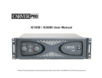
Xi850 / Xi1150 User Manual A Product of Phoenix Gold International, Inc. 9300 North decatur Street Portland, Oregon 97203 Tel: 503.286.9300 Fax: 503.978.3302 www.carverpro.com CAUTION RISK OF ELECTRIC SHOCK DO NOT OPEN ! CAUTION: TO REDUCE THE RISK OF ELECTRIC SHOCK, DO NOT REMOVE THE COVER. NO USER SERVICABLE PARTS INSIDE. REFER SERVICING TO QUALIFIED PERSONNEL! Please read this entire manual, especially the Instructions and Warnings, before operating Explanation of Symbols TO PREVENT ELECTRIC SHOCK DO NOT REMOVE TOP OR BOTTOM COVERS. NO USER SERVICEABLE PARTS INSIDE. REFER SERVICING TO QUALIFIED SERVICE PERSONNEL. The lightning flash with the arrowhead symbol within an equilateral triangle is intended to alert the user to the presence of uninsulated dangerous voltage within the products enclosure that may be of sufficient magnitude to constitute a risk of electric shock to persons. ! FCC COMPLIANCE NOTICE This device complies with part 15 of the FCC rules. Operation is subject to the following two conditions: (1) This device may not cause harmful interference, and (2) this device must accept any interference received, including interference that may cause undesired operation. The exclamation point within an equilateral triangle is intended to alert the user of the presence of important operating and maintenance (servicing) instructions in the literature accompanying the appliance. IMPORTANT SAFETY INSTRUCTIONS CAUTION: Changes or modifications not expressly approved by the party responsible for compliance could void the users authority to operate the equipment. 1) 2) 3) 4) 5) 6) 7) 8) Read these instructions. Keep these instructions. Heed all warnings. Follow all instructions. Do not use this apparatus in or near water. Clean only with a dry cloth. Do not block any ventilation openings. Install in accordance with the manufacturers instructions. Do not install near any heat sources such as radiators, heat registers, stoves, or other apparatus that produce heat. 9) Do not defeat the safety purpose of the polarized or grounding-type plug. A polarized plug has two blades with one wider than the other. A grounding-type plug has two blades and a third grounding prong. The wide blade or the third prong is provided for your safety. If the provided plug does not fit into your outlet, consult an electrician for replacement of the obsolete outlet. 10) Protect the power cord from being walked on or pinched, particularly at plugs, convenience receptacles, and the point where they exit from the apparatus. 11) Only use attachments/accessories specified by the manufacturer. 12) Unplug this apparatus during lightning storms or when unused for long periods of time. 13) Refer all servicing to qualified service personnel. Servicing is required when the apparatus has been damaged in any way, such as power supply cord or plug is damaged, liquid has been spilled or objects have fallen into the apparatus, the apparatus has been exposed to rain or moisture, does not operate normally, or has been dropped. NOTE: This equipment has been tested and found to comply with the limits for a Class B digital device, pursuant to part 15 of the FCC Rules. These limits are designed to provide reasonable protection against harmful interference in a residential installation. This equipment generates, uses, and can radiate radio frequency energy and, if not installed and used in accordance with the instruction manual, may cause harmful interference to radio communications. However, there is no guarantee that interference will not occur in a particular installation. If this equipment does cause harmful interference to radio or television reception, which can be determined by turning the equipment off and on, the user is encouraged to try to correct the interference by one or more of the following measures: Reorient or relocate the receiving antenna. Increase the separation between the equipment and receiver. Connect the equipment into an outlet on a circuit different from that to which the receiver is connected. IMPORTANT Xi850 and Xi1150 amplifiers require Class 2 output wiring. MAGNETIC FIELD CAUTION! Do not locate sensitive high-gain equipment such as preamplifiers or tape decks directly above or below the unit. Because this amplifier has a high power density, it has a strong magnetic field, which can induce hum into unshielded devices that are located nearby. The field is strongest just above and below the unit. If an equipment rack is used, we recommend locating the amplifier(s) in the bottom of the rack and the preamplifier or other sensitive equipment at the top. TO REDUCE THE RISK OF FIRE OR ELECTRIC SHOCK, DO NOT EXPOSE THIS APPARATUS TO RAIN OR MOISTURE. 2 TABLE OF CONTENTS INTRODUCTION Safety Instructions Important Safety instructions FCC Compliance Notice Magnetic Field Warning 2 2 2 2 Congratulations on choosing the Carver Professional Xi Series Amplifier! The Xi Series amplifiers have superior fidelity and the capability to drive low impedances. Our Xi Series can deliver generous power levels, even at 2 Ohm stereo loads. By design, the Xi Series power amplifiers are very accurate and efficient. Your Xi Series amplifier will give you many years of outstanding service and reliability. Table of Contents 3 Unpacking Introduction Unpacking Important Paperwork 3 3 3 Inside the box you will find; one Xi Series Amplifier, four self-adhesive rubber feet, and an owners manual and warranty card. Power Specifications 4 Features 4 Carefully unpack the amplifier and keep the original carton and packing materials for future moving, shipment or long-term storage. After opening the box, please check for visible signs of damage that were not apparent from the outside of the box. If you encounter what appears to be concealed damage, please consult your Carver Professional Dealer before installing unit. Front Panel Controls & Features 5 Important Paperwork Rear Panel Controls & Features 6 Installation Location and General Precautions Mechanical Considerations Rear Support for Road Applications Thermal Considerations AC Power Considerations Magnetic Leakage Considerations Input Wiring Output Wiring Multi-Way Binding Posts Speakon Polarity Bridged Mono Operation Dual Mono Operation DIP Switches Signal Smart 70 Volt Direct Drive 7 7 7 7 7 7 7 7 7 8 8 8 8 8 8 8 9 Make sure to save your sales receipt. Your receipt is extremely important to establish the duration of your Limited Warranty and for insurance purposes. Next, make a note of the serial number, which is located on the back of the amplifier. Record it in the space provided below for convenient reference. Performance Specifications 9 Warranty Information 10 Care and Service Assistance 10 In Case of Difficulty 11 Serial Number:_______________________ Purchased at: __________________________ Date:______________________ Finally, take a moment to fill out the Warranty Registration Card packed with the amplifier and return it to Carver Professional. This will allow us to keep you informed about new products as they become available. 3 CHANNEL 1 CLIP CHANNEL 2 ON SIGNAL POWER THERMAL STANDBY 8 8 PROTECT 0dB Xi850 0dB Xi850 OFF POWER SPECIFICATIONS Xi1150 200W per channel into 8 ohm stereo loads, 20 Hz to 20 kHz, with less than 0.5% THD+N 225W per channel into 8 ohm stereo loads, 20 Hz to 20 kHz, with less than 0.5% THD+N 300W per channel into 4 ohm stereo loads, 20 Hz to 20 kHz, with less than 0.5% THD+N 450W per channel into 4 ohm stereo loads, 20 Hz to 20 kHz, with less than 0.5% THD+N 375W per channel into 2 ohm loads, 1 kHz, with less than 1% THD+N 550W per channel into 2 ohm loads, 1 kHz, with less than 1% THD+N 600W bridged mono into 8 ohms, 20 Hz to 20 kHz with less than 1% THD+N 900W bridged mono into 8 ohms, 20 Hz to 20 kHz with less than 1% THD+N 750W bridged mono into 4 ohms, 1 kHz with less than 1% THD+N 1100W bridged mono into 4 ohms, 1 kHz with less than 1% THD+N FEATURES Stable 2 Ohm operation Variable speed ultra-quiet fan cooling 7 LED level display, per channel, including signal present and clip indicators Power ready, Signal Present, Clip, Protect, Thermal and Standby LED indicators for each channel Level control defeat can be accessed from rear panel Switched 40 Hz / 80 Hz (12 dB/octave cut) High Pass and Low Pass Filters Switched Soft Knee Clip Limiters Soft Start In-Rush Current Limiting Input via 1/4 TRS and XLR connectors Speaker Outputs via Neutrikâ Speakonâ connectors Speaker Outputs via two pairs of Multi-Way binding posts Power Switch, 2 positions: ON, OFF Heavy Duty AC Line Cord Optional Accessories: 70 Volt Line Transformer 4 Front Panel Controls and Features CHANNEL 1 CLIP CHANNEL 2 ON SIGNAL POWER PROTECT 1 THERMAL STANDBY 2 Xi1150 0dB 8 8 0dB 3 OFF 4 5 1 Channel 1 Level Control is a 41 detent potentiometer allowing adjustment from infinite attenuation to 0dB attenuation in 40 steps. Level controls may be bypassed from rear panel. 3 Channel 2 Level Control is a 41 detent potentiometer allowing adjustment from infinite attenuation to 0dB attenuation in 40 steps. Level controls may be bypassed from rear panel. 2 Status LEDs - From top to bottom: One Red Clip indicator per channel, one Yellow Signal Present indicator per channel, one Green Power ON indicator per channel, one Red Protection indicator per channel, one Red Thermal Overload indicator per channel and one Yellow Standby indicator per channel. 4 Ventilation openings for fan cooling. Caution should be taken to keep the ventilation opening free from any obstruction to assure proper cooling. The fans force air from the back to front of the Xi amplifiers. 5 Power Switch - Press up for the ON position or press down for the OFF position. 5 Rear Panel Controls and Features 2 9300 North Decatur St. Portland, OR 97203 Custom Manufactured In China BRIDGED MONO CH 2 CLASS 2 WIRING MAY BE USED FOR 2 CHANNEL OPERATION. + ENERGIE ELECTRIQUE DANGEREUSE. VOIR LA NOTICE DE FONCTIONNEMENT. RISK OF HAZARDOUS ENERGY! MAKE PROPER SPEAKER CONNECTIONS. SEE OPERATING MANUAL BEFORE USING. 3 -40dB BYP WARRANTY VOID IF REMOVED - 4 5 6 CH 2 1 AC Mains Circuit Breaker will protect the amplifier against excessive current draw. Should the breaker trip, wait, turn off the power switch, then press in to reset. OFF LPF 120 LP ON HPF 80 HP ON 0.775 LVL 2 CH LIMIT 80 OFF 40 OFF 1.55 BYP MONO CH 1 8 7 LIMIT 80 OFF 40 OFF 1.55 BYP BRDG DO NOT REMOVE SERIAL NO. BRIDGED MONO OFF LPF 120 LP ON HPF 80 HP ON 0.775 LVL DUAL MODEL NO. -20dB SIGNAL SMART + - 1 CH 1 CH 2 WARNING CH 1 CLASS 1 WIRING MUST BE USED FOR BRIDGED MONO OPERATION. FOR BRIDGED OPERTION CONSULT USER MANUAL. AVERTISSEMENT 9 7 10 11 7 Cooling Fans. Care should be taken to insure that the fans are always in proper working order and that they are clean and free from any build up of dust or debris. Never place the amplifier in a position that would block the free flow of fresh air from the fans. The direction of airflow is from the rear to the front of the amplifier. 2 AC Mains Power Cord. Caution should be used to protect the power cord from damage to prevent the possibility of electric shock. 8 Input connectors. An XLR connector and a 1/4 TRS connector are provided for each channel. Within a channel the XLR and TRS connectors are wired in parallel. 3 Channel 2 Speakon R connector. Used to connect speakers to Channel 2. Speaker wire should be connected to Pin1+ and Pin1- within the mating connector. 9 Threshold adjustment for the Signal Smart feature of the amplifier. 4 Channel 2 Multi-way Binding post speaker connectors. Red is positive and Black is negative. Take care to assure no frayed strands of wire are bridging between the connectors. This can be simplified by not stripping an excessive amount of insulation from the speaker wire. 10 Serial Number Label should not be removed. This label contains the serial number and manufacturing information, and removal will void the products warranty. 5 Channel 1 Multi-way Binding post speaker connectors. Red is positive and Black is negative. Take care to assure no frayed strands of wire are bridging between the connectors. This can be simplified by not stripping an excessive amount of insulation from the speaker wire. 11 DIP Switches for selecting and setting various features of the amplifier. 6 Channel 1 Speakon R connector. Used to connect speakers to Channel 1. Speaker wire should be connected to Pin1+ and Pin1- within the mating connector. Channel 1s Speakon R connector can be used to deliver the speaker level audio to a single speaker when the amplifier is set to the MONO configuration. See page 8 for more information. 6 Installation Location and General Precautions Observe the following precautions when choosing a location for your amplifier. A. Do not expose the unit to rain or moisture. If a fluid or foreign object should enter the unit, disconnect the power plug and contact an authorized dealer or service center. Do not pull out the plug by pulling on the cord; grasp the plug firmly and pull from socket. The input signal can be used with either unbalanced shielded single conductor or balanced shielded two conductor cables. Use shielded cable to conduct the signal from the source (i.e. mixer, equalizer, CD player, etc.) to the amplifier. B. Protect from heat and allow adequate ventilation. Place away from direct sources of heat, such as heating vents and radiators. All components produce some heat during operation, so make sure that the ventilation holes are not covered and that air is allowed to circulate freely behind, beside and above the amplifier. Excessive heat is the single greatest cause of component failure. 1/4 Phone Jack: Use a 3-conductor TRS (tip-ring-sleeve) 1/4 Phone Plug. The tip carries the + (high, non-inverted) side of the signal, the ring carries the - (low, inverted) side of the signal and the sleeve is signal ground (see Figure A). Balanced Connection For Balanced Operation: Mechanical Considerations The Xi850 and Xi1150 require three rack space units (5.25) and a depth of 16 inside the rack, including the rear supports. Secure the unit mechanically using four screws with washers to prevent marring the front panel. Figure A Balanced Connection Rear Support for Road Applications If the Xi amplifier is rack mounted and the rack is transported, mechanical support for the rear of the amplifier is required. This could take the form of a shelf across the rear of the amplifier or brackets that engage the rear of the amplifier. Rear support is recommended in all Xi amplifier installations. 1 2 XLR: Use a male XLR connector. Pin 2 carries the+ (high, non-inverted) side of the signal, Pin 3 carries the - (low, inverted) side of the signal and Pin 1 is signal ground. (See Figure B). 3 Figure B For Unbalanced Operation: Unbalanced Connection 1/4 Phone Jack: Use a 3-conductor TRS (tip-ring-sleeve) 1/4 Phone Pug. The tip carries the + (high, non-inverted) side of the signal, the sleeve is signal ground connect the sleeve to the ring. (see Figure C). Thermal Considerations When the Xi amplifiers are used free-standing, no thermal considerations are necessary other than keeping the ventilation holes open. If the amplifiers are rack mounted, ensure that adequate ventilation exists if front of and behind the amplifier. When several amplifiers are mounted together in a rack, you may need to provide air inlets from the outside of the rack. The Xi amplifiers are fan cooled. The fan is internally mounted so that it draws air from the rear of the chassis and exhausts it out the front. The Xi amplifiers may be stacked directly on top of each other without spacer panels. If the amplifiers are used with other amplifiers, ensure that the heat output from the other amplifiers does not interfere with the ventilation of the Xi amplifiers (or vice versa). XLR: Use a male XLR connector. Pin 2 carries the+ (high, non-inverted) side of the signal, Pin 1 is signal ground, Pin 3 is jumpered to Pin 1. (See Figure d). AC Power Considerations Ensure that the Xi amplifier is plugged into an outlet capable of supplying the correct voltage specified for your model and enough current to allow full-power operation of all amplifiers plugged into the outlet. The current demand of a power amplifier varies depending on several factors, including the impedance of the load, the output level of the amplifier, and the crest factor and duty cycle of the program material. Under typical conditions reproducing rock music, with both channels driven into a 4 ohm load to the point where musical peaks are just at the clipping point, the amplifiers require the following current: Xi850: 375W (5.1A) for 117V versions, 375W (2.6A) for 234V versions Xi1150: 550W (7.2A) for 117V versions, 550W (3.8A) for 234V versions Better Method Optional Method Figure C Unbalanced Connection Input Sensitivity The input sensitivity of the Xi amplifiers is set at the factory to 1.55VRMS for rated output. The input sensitivity can be changed to 0.775VRMS by using the appropriate DIP switch on the rear panel. The input sensitivity can be set independently for each channel. Magnetic Leakage Considerations The Xi amplifiers may be mounted without concern for magnetic flux leakage, within the confines of common sense. For example, it is not a good idea to mount a power amplifier near a microphone input transformer or magnetic storage media. 7 1 2 3 1 2 3 Better Method Optional Method Figure D Output Wiring Use heavy gauge cable for speaker connections. The greater the distance between the amplifier and the speakers, the larger the diameter the cable should be to minimize power losses across the cable and improve the damping of the speaker. Cable thickness specifications (or gauges) get larger as the cable gets thinner; thus 14-gauge cable is thicker than 16-gauge cable. Use the following as a guide: Up to 25 feet use 16-gauge, up to 40 feet use 14-gauge, up to 60 feet use 12-gauge, up to 100 feet use 10-gauge, up to 150 feet use 8-gauge and up to 250 feet use 6-gauge speaker cable. This will ensure that the resistance of the speaker cable is less than 5% of 4-ohms, resulting in a transmission loss of less than 0.5 dB. With Xi amplifiers Class 2 (NEC) cable may be used. In Bridged Mono operation Class 1 (NEC) cable must be used. DIP Switches The Xi Amplifiers have an eight position DIP switch located at the input of each channel on the rear of the amplifier. (see Figure F) CH1 DIP Switch(top to bottom) Clip Limiter Low Pass (select 120Hz or 80Hz) Low Pass Filter (select On / Off) High Pass (select 80Hz or 40Hz) High Pass Filter (select On / Off) Sensitivity (select 0.775V or 1.55V) CH1 Level Control Bypass Mono Operation (select Dual or Bridged) Multi-Way Binding Posts Xi amplifiers can accept spade connectors, bare wire, or banana connections (except CE approved versions). Be sure that all the fine strands of the cable are twisted together and contained within the connector. If even one strand is loose and can touch the adjacent terminal, a short circuit may result. CH2 DIP Switch(top to bottom) Clip Limiter Low Pass (select 120Hz or 80Hz) Low Pass Filter (select On / Off) High Pass (select 80Hz or 40Hz) High Pass Filter (select On / Off) Sensitivity (select 0.775V or 1.55V) CH1 Level Control Bypass Operation (select 2 Channel or Mono) Speakon NL4 Pinout Speakon R Must use Neutrik R SpeakonR 4 position female connector (NL4FC) or equivalent. Use speaker cable gauges as specified above for optimum performance. Stereo or paralleled configuration for both channels: Pin 1+ is positive, and Pin1- is negative. Using the Mono Bridged connector, (CH1) Pin 2+ is positive and Pin1+ is negative. (see Figure E) Figure E Polarity Loudspeakers must be connected with consistent polarity for correct phasing between them. Incorrect phasing will do no physical harm, but frequency response will be affected. The key is to make sure that both speakers connected to the speaker terminals are hooked up the same way. Connect (-) at the speaker outputs to (-) on the back of the speaker, and (+) at the speaker outputs to (+) on the back of the speaker. Signal Smart Signal Smart is an energy saving circuit in the Xi amplifiers. When the amplifier is idle for more than three minutes Signal Smart will cause the amplifier to go into a standby mode that significantly reduces current draw in the amplifier. Bridged Mono Operation When in Bridged Mono mode, connect the input signal to CH2 input (CH1 input becomes disabled). Connect the speaker(s) to the two red (+) binding posts. The CH2 (+) terminal is the hot (+) (non-inverting) side, and the CH1 (+) terminal is the low (-) (inverting) side. When connected in this way, each channel sees one-half the impedance of the speaker(s) connected between them. If and 8-ohm speaker is used, each channel will see a 4-ohm load. Therefore, it is not recommended that any load lower than a 4-ohm load be connected in this mode of operation. In Bridged Mono operation Class 1 (NEC) cable must be used. Use Dual Mono mode for lower impedances. (To use Speakon connectors in Bridged Mono mode see the paragraph above refencing Speakon R ) ! LIMIT 80 OFF 40 OFF 1.55 BYP BRDG OFF LPF 120 LP ON HPF 80 HP ON 0.775 LVL 2 CH LIMIT 80 OFF 40 OFF 1.55 BYP MONO Figure F CH 1 SIGNAL SMART -20dB -40dB BYP Find the Signal Smart Threshold adjustment on the rear of the amplifier (see figure G). A range from -40dB to -20dB is available. At -40dB very little signal is required to keep the amplifier turned ON and is considered to be a Bypass setting for the Signal Smart feature. At a setting of -20dB a much larger amount of signal is required to overcome the standby function of the signal smart circuit. A setting of about -30db will be virtually transparent to CH 2 CH 1 the user. Once the threshold has been passed an Figure G amplifier that is in standby will return to its full potential in approximately 40 milliseconds, or about the time it take to blink your eyelid. Sonically, this is transparent and causes little or no abbreviation of the sound if the threshold is not set to high (-20db). NOTE: Be sure to set both CH1 and CH2 input level controls to the same setting for equal power distribution to the inverted and non-inverted signals. WARNING: In bridged mono operation, the output connections are actually a balanced output configuration. This means that both output terminals have potentially high voltages present (neither one may be grounded). Dual Mono To configure the amplifier for Dual-mono operation, change the output configuration switches located on the rear panel of the amplifier. Connect the input source to CH2 (CH1 input is now disabled). Connect speaker(s) to either CH1, or CH2, or both. OFF LPF 120 LP ON HPF 80 HP ON 0.775 LVL DUAL Turning the threshold control fully counter-clockwise will bypass the Signal Smart feature on the amplifier. 8 Performance Specifications 70V Direct-Drive Operation: The Xi850 has sufficient output voltage capability in bridged mono mode to direct-drive 70-volt distribution systems without using a step-up transformer at the amplifier. In this configuration, the Xi850 delivers up to 600 watts to the 70V system, depending on the impedance of the total system. As with all 70V systems, step-down transformers are still required at each loudspeaker. The Xi850 can deliver 600 watts into an 8 ohm impedance (69.28V line voltage). Xi850 / Xi1150 THD+N: <0.5% @ rated power (8 ohm), 20-20kHz <0.5% @ rated power (4 ohm), 20-20kHz 1% @ rated power (2 ohm), 1kHz 1% @ rated power (8 ohm), bridged 1% @ rated power (4 ohm), bridged IMD (SMPTE): <0.2%, 60Hz/7kHz, 4:1, 35Vpeak @ 4 ohms Dynamic Headroom: 1.5dB Power Bandwidth: 20-20 kHz @ 4 and 8 ohm loads Frequency Response: 20-20kHz, +0dB/-1dB Signal-to-Noise: >100dB, A-Weighted, referenced to 4 ohm rated power Crosstalk: > -70dB @1kHz referenced to rated power (4 ohm) CMRR: 70dB at 1kHz Slew Rate: 20V/uSec Sensitivity for rated power: 0.775Vrms or 1.55Vrms (Selectable) Input Impedance: 50k balanced Input Overload: 20dBu Protection: Thermal, Short Circuit, Over-Current & Over Voltage Stability: Unconditionally stable into reactive loads at 1/3 rated output power Duty Cycle: Continuous operation at 1/3rd power The Xi1150 has sufficient output voltage capability in stereo mode to direct-drive 70-volt distribution systems without using a step-up transformer at the amplifier. In this configuration, the Xi1150 delivers up to 225 watts per channel to the 70V system, depending on the impedance of the total system. As with all 70V systems, step-down transformers are still required at each loudspeaker. The Xi1150 can deliver 225 watts per channel into an 8 ohm impedance (42.43V line voltage). The price for going direct is having to calculate the new transformer tap values at the new line voltage. Since watts are proportional to the square of the voltage, compute the correction factor by taking the ratio of the square of the line voltages. then multiply each tap value by this correction factor. For example, choose a transformer that has tap values at 10W, 5W and 2.5W when used in a 70.7 volt distributions system. Its new tap values when used with an Xi850 are computed as follows: 1) Complete correction factor K: POWER REQUIREMENTS: K=69.28V2/70.7V2 K=0.59 Mains Voltage (output power rated at nominal voltage): 2) Apply to tap value: 10W x 0.96= 9.6W 5W x 0.96= 4.80W 2.5W x 0.96= 2.4W Current consumption @ 1/8 rated power, pink noise: Its new tap values when used with an Xi2600 are computed as follows: 1) Complete correction factor K: K=42.43V2/70.7V2 K=0.36 2) Apply to tap value: 10W x 0.36= 3.6W 5W x 0.36= 1.8W 2.5W x 0.80= 0.9W When used in a 70.7 volt distribution system, this transformers new tap values are as noted above. Note that the 3dB power relationship between each tap still holds true. Similarly, maximum amplifier loading occurs when the sum of the New tap values equals the amplifiers output power per channel into the 8-ohm load. 9 100VAC (50-60Hz) ±10% 117VAC (60Hz) ±10% 234VAC (50Hz) ±10% Xi1150 8-ohm x 2 300W (3.9A) 117V/60Hz 4-ohm, x 2 550W (7.2A) 117V/60Hz 2-ohm x 2 825W (10.6A) 117V/60Hz 300W (2.0A) 234V/50Hz 550W (3.8A) 234V/50Hz 825W (5.5A) 234V/50Hz Xi850 8-ohm x 2 250W (3.6A) 117V/60Hz 4-ohm, x 2 375W (5.1A) 117V/60Hz 2-ohm x 2 550W (7.0A) 117V/60Hz 250W (1.8A) 234V/50Hz 375W (2.6A) 234V/50Hz 550W (3.6A) 234V/50Hz Limited Warranty Information Xi Series Power Amplifiers: 5 Years* STATE LAWS MAY DIFFER: Some states do not allow limitations on how long an implied warranty lasts and/or do not allow the exclusion or limitation of incidental or consequential damages, so the above limitations may not apply to you. This warranty gives you specific legal rights, and you may have other rights, which vary, from state to state. * The following limited five year warranty is exclusive to the United States and its possessions and territories. In all other countries the warranty is limited to two years. Please see your Carver Professional dealer or distributor for the correct limited warranty information in your area or locale. OTHER IMPORTANT PROVISIONS: Carver Professional reserves the right to make changes in design and improvements to its products without the responsibility of installing such changes or improvements on products previously sold by Carver Professional. We suggest that you attach your purchase receipt to this Warranty and keep both documents in a safe place. Thank you for your choice of a Carver Professional Amplifier. WHAT IS COVERED: THIS LIMITED WARRANTY COVERS DEFECTS IN MATERIAL AND WORKMANSHIP ONLY. This limited Warranty DOES NOT extend to: 1) damage caused by shipment, 2) damage caused by accident, misuse, abuse, failure to perform owner maintenance, or operation contrary to the instructions in the Carver Professional owners manual, 3) units on which the serial number has been defaced, modified or removed and 4) damage resulting from modification or attempted repair by any other person than authorized by Carver Professional. CARE AND SERVICE ASSISTANCE Care: Wipe off the Xi Series Amplifiers front panel and chassis from time to time, with a soft, dry cloth. If you have something stubborn to remove, use a mild dish soap or detergent sparingly applied to a soft cloth. Dont use alcohol, ammonia or other strong solvents. Service Assistance: We suggest that you read the Limited Warranty completely to fully understand your warranty/service coverage. Please promptly complete and return the Warranty registration card. Also, be sure to save the sales receipt in a safe place. It will be necessary for warranty service. If your Carver Professional product should require service, you may contact the Carver Professional Technical Service Department by calling (503) 978-3399 or by writing to us at the Factory address below. We will then direct you to the nearest in our national network of Authorized Warranty Service Centers, or give you detailed instructions on how to return the product to us for prompt action. If you should have questions or comments, please write to the Factory address below, or contact us via email at [email protected] or at our web site: www.carverpro.com. Please include the model and serial number of your Carver Professional product, your complete address and daytime phone number. WHAT WE WILL PAY FOR: Carver Professional will pay all labor and material expenses for items covered under this Limited Warranty. See the next section concerning shipping charges. WHAT YOU MUST DO TO OBTAIN WARRANTY SERVICE: In the event your Carver Professional product requires service, contact your Carver Professional Authorized Dealer / Contractor or contact Carver Professional (ATTN: Customer Service Dept.) 9300 North Decatur, Portland, OR 97203, or call Customer Service Department directly at (503) 978-3317. You will be directed to an Authorized Carver Professional Service Station or receive instructions to ship the unit to the factory. Please save the original carton and packing materials in case shipping is required. Please do not ship parcel post. Include a complete description of the problem, the associated components and connections, and a copy of the purchase receipt. Carver Professional does not pay initial shipping costs. Return shipping costs will be pre-paid if repairs were covered by the scope of this warranty. Carver Professional Service Department 9300 North Decatur Street Portland, Oregon 97203 Phone 503.978.3317 Fax 503.978.3302 Email: [email protected] Web: www.carverpro.com YOU MUST RETAIN AND PROVIDE YOUR SALES RECEIPT TO OBTAIN COVERAGE UNDER THIS LIMITED WARRANTY. The warranty period begins from the date of the first consumer purchase from an Authorized Carver Professional Dealer. Any implied warranties for merchantability and fitness for a particular purpose required by any state law are limited in duration to the warranty period of your product. The warranty set forth above is exclusive and no other, written or oral is expressed or implied. Carver Professional specifically disclaims the implied warranties and merchantability and fitness for a particular purpose. Carver Professional Customer Support 9300 North Decatur Street Portland, Oregon 97203 Phone 503.286.9300 Fax 503.978.3302 Email: [email protected] Web: www.carverpro.com EXCLUSION OF CERTAIN DAMAGES: In no event shall Carver Professional be liable for property damage, or any other incidental or consequential damages, which may result from failure of this product. If your Carver Professional product proves defective in material or workmanship, the liability of Carver Professional shall be limited to the repair or replacement, at the option of Carver Professional, of any defective part. Carver Professional reserves the right to improve its products at any time. Therefore, specifications are subject to change without notice. 10 IN CASE OF DIFFICULTY Notes If you are having trouble, or suspect a problem with your Xi Series amplifier, try some simple troubleshooting before contacting an Authorized Carver Professional Dealer, Authorized Carver Professional Service Center or Carver Professional Technical Service. Below are listed some general problems and items that should be checked in an attempt to resolve the difficulty. No Sound, No Power This is usually an indication of a power supply problem in either the power line itself or the amplifiers power supply. Check the following: 1) Xi Series amplifiers power is switched off. 2) Line cord is disconnected. 3) Poor fit between the plug and AC receptacle. 4) Power off at AC receptacle (check with tester or lamp). 5) The amplifier is plugged into a switched outlet. Verify that the outlet is live. 6) Xi Series amplifiers mains breaker has blown. This amplifier contains no user serviceable fuses inside the chassis. Power On, Low Output or No Output Low or no output problems are usually signal-source, bad cable or partial output short circuit related. 1) The input level sensitivity controls are set too low. 2) Move the input connection to another amplifier that you know is working to verify that it is not a source problem. 3) Check speaker connections. Be sure that there are no small strands of wire touching similar strands coming from the other wire in the cable. 4) Make sure the speakers are functioning correctly. 5) If you are using bridged-mono mode, ensure that the Input and Output configurations are set correctly. 6) Use a voltmeter to determine if the power line voltage is dropping excessively when the amplifier is driven hard. 7) The thermal breaker in the power transformer has opened. Allow amplifier to cool and the breaker will reset itself. Playback Is Mixed with Hum 1) 2) 3) 4) Check or replace the connecting cables, between source and amplifiers input. Make sure that each screw terminal connection is tight. Signal cables may have been routed too closely to the AC cables, power transformers, motors or EMI inducing device. Try connecting another source to the power amplifier inputs. If the hum stops, the problem lies with the original source component. Distortion Distortion is usually caused by excessive loss in the input controls (the mixer/equalizer/crossover cannot produce enough output), overdriving resulting in output clipping, or current limiting caused by excessively low load impedance. 1) Check the setting of the input level sensitivity controls. If set too high, the preceding piece of equipment may overdrive the input stage. 2) Check the speaker connections and verify that all screw connections are tight and that there are no stray strands of wire to cause short circuits. 3) Verify that the total load impedance presented to the amplifier is within the limits described in this manual for mode of operation selected. 11 Carver Professional 9300 North Decatur Street Portland, Oregon 97203 Phone 503.286.9300 Fax 503.978.3302 Email: [email protected] Web: www.carverpro.com 8100.0306A