1
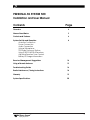
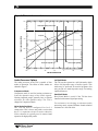
Installation
Guide &
User
Manual
PERSONAL PA System 500
Narrow-Band FM Wireless Listening System
Transmitter Model T20
Receiver Model R19/*, R19-4A, R19-6
MAN 062B
®
Williams
Sound
Helping People Hear
PERSONAL PA SYSTEM 500
Installation and User Manual
Contents
Page
Overview
4
Narrow-Band Basics
5
Controls and Features
6
System Set-Up and Operation
Antenna Connection
Power Connection
Audio Connection
Using a Microphone
T20 Audio Processor Options
Using R19/R19-4/R19-6 Receivers
Adjusting Receiver Tone Controls
Battery & Charger Information
8
Receiver Management Suggestions
14
Using a Remote Antenna
15
Troubleshooting Guide
16
Radio Interference / Tuning Instructions
18
Warranty
19
System Specifications
20
Williams
Sound ®
Helping People Hear
3
Overview
Thank you for purchasing the Personal PA System
500 from Williams Sound Corp. The PPA System
500 is a Narrow-Band FM Listening System which
operates in the 72-76MHz frequency band. Designed
for hearing assistance in places of public access, the
PERSONAL PA System 500 is for those who need
help overcoming background noise, reverberation, or
distance from the sound source. The versatile PPA
500 is easily integrated with your existing sound
system or can be used with a microphone as a standalone system.
To avoid difficulties, please read through this manual
as you begin to use the system. Then save it for
questions that arise as you continue to use your
PERSONAL PA System 500.
If you have any problems with this Williams Sound
product, don’t hesitate to call us toll-free at
1-800-843-3544.
Your PPA System 500 has two principal parts: the
T20 Transmitter and the R19, R19-4, or R19-6
Receivers. Much like a miniature radio station, the
transmitter and microphone pick up the sounds you
want to hear and broadcast them over an FM radio
signal. The receivers are used to pick up the
broadcast up to 500 feet away.
Figure 1: Overall System Diagram
Microphones
Sound System Amplifier
Loudspeakers
Line-Level Output
FM Auditory AssistanceTransmitter
Power
Audio Level
Ok
R19 / R19-4 / R19-6 Narrow-Band
Receivers w/Earphones
4
Hi
+
Adjust
Williams Sound
Line-Level Input
Transmit Status
On
WB
NB
Tape Out/Phones
T20 Transmitter
Williams
Sound ®
Helping People Hear
Narrow-Band Basics
Less Interference
Sound Quality
All FM receivers are tuned to a specific carrier
frequency. The selectivity of the receiver determines
how close nearby radio signals can be to this carrier
frequency before interference occurs. True narrowband receivers like the Williams Sound R19 use
dual-conversion circuitry to achieve a very narrow
“window” of acceptance for radio signals. This
allows them to operate in areas that have a lot of
different radio signals with less likelihood of
receiving interference.
Narrow-band systems give up some frequency
response (extended highs and lows) and noise
performance compared to wide-band systems. This
is usually not a drawback for spoken word
presentations, but may not be optimal for programs
which are primarily music.
More Simultaneous Channels
This narrow window of acceptance means more
channels can be squeezed into the designated
frequency band. Instead of dividing the Auditory
Assistance Band (72-76MHz) into 10 wide channels
(wide-band), the same band can be divided into 40
closely spaced (narrow-band) channels. The
selectivity of the R19 dual conversion receiver
allows you to operate on these closely-spaced
channels without interference from the next channel.
Greater Operating Range
Another measure of FM receiver performance is
sensitivity, measured by the weakest radio signal that
the receiver can respond to and still operate properly.
All hearing assistance transmitters are limited by
FCC Rules to the same transmitted signal strength,
so you can’t boost transmitter power or antenna
efficiency to get more operating distance. The
farther you move from the transmitting antenna, the
weaker the signal becomes. A very sensitive receiver
like the R19 will allow greater operating distance.
Because of its excellent operating distance, the PPA
System 500 can be used in situations where
maximum coverage area is needed.
Williams
Sound ®
Helping People Hear
Manufacturers often list a minimum signal strength
needed to maintain an acceptable noise level in the
receiver before it “squelches” or goes quiet. The
Williams Sound R19 receiver is designed to offer
maximum sensitivity with minimum noise and a
reasonable squelch action.
Overload Protection
Making a receiver sensitive for greater reception of
weak signals can create a problem when the receiver
is used in an area that has strong radio signals.
Unless the receiver has a superior dynamic range, it
can be overloaded by the strong signal and become
noisy, distorted, or vulnerable to interference. The
Williams Sound R19 receiver uses state-of-the-art
circuitry for improved RF dynamic range.
Capture Effect
When an FM receiver is presented with two radio
signals on the same channel, it will “lock on” to
whichever signal is stronger. This is called the
“capture effect.” Because signal strength is related to
distance, this usually means that the closest
transmitter antenna will produce the strongest signal
and “capture” the receiver.
5
Controls and Features
Receiver Model R19
Transmitter Model T20
EAR Jack
See Figures 3 and 4.
Mono 3.5 mm mini earphone jack
Off/On Indicator Light
Red LED which indicates receiver is “on” when lit.
If the batteries are near end of life and the LED turns
off while the receiver is operating, approximately
one hour of battery life remains.
Tone Control
3-position switch which cuts low frequencies at certain
thresholds: (Lo: 20 Hz, Mid: 120 Hz, Hi: 700 Hz)
Volume/On-Off Control
Combination volume and on-off rotary control.
Channel Slide Switch
2-position slide switch used to alternate between two
pre-set narrow-band frequencies. Standard channels
are 33 and 53. See page 18 for instruction on
changing system frequencies.
Figure 2: R19 Receiver Controls
EAR Jack
Tone Control
Volume/On-Off Control
Mono 3.5 mm mini earphone jack
Three-position switch which cuts low
frequencies at certain thresholds:
Combination volume and on-off rotary
control.
EAR
Volume Channel
Lo Mid Hi
1
2
Off/On Indicator Light
Red LED which indicates
receiver is “on” when lit.
6
2
Channel Slide Switch
2-position slide switch used to
alternate between two pre-set
narrow-band frequencies.
Tone
Off
Max
Williams
Sound ®
Helping People Hear
Figure 3: T20 Front Panel Controls & Features
Audio Indicators:
Tape Out/Phones:
Amber LED "Ok" for nominal input signal level
Red LED "Hi" for excessive input signal level
1
⁄4" jack, 600 mV, 100 Ω source impedance. Also drives
mono or stereo headphone. Monitors exactly what is being
transmitted.
FM Auditory AssistanceTransmitter
Power
Audio Level
Ok
Hi
Williams Sound
Transmit Status
+
Adjust
On
WB
Tape Out/Phones
NB
Power Indicator:
Audio Level Control:
RF Indicators:
Green LED
Rotary pot, screwdriver adjust,
used with audio indicator lights
Green LED "On" indicates transmitter RF is on
Amber LED "WB" indicates wide–band channel is selected
Amber LED "NB" indicates narrow–band channel is selected
Figure 4: T20 Rear Panel Controls & Features
Audio Inputs:
Unbal. Audio Inputs:
Remote Antenna Output:
All inputs are actively mixed into a single
signal, allowing use of mono, stereo,
3 channel or 4 channel audio sources
Four screw terminals, three unbalanced
line-level inputs,
one ground, actively mixed
F-type connector for 75 Ω Coaxial
Antenna (ANT 005) uses RG-59 cable.
Balanced Audio Input
COM
IN 1
IN 2
IN 3
FM Auditory AssistanceTransmitter
Unbalanced
Audio Inputs
Antenna
75 Ohm
Channel
Select
Hi-Pass Filter
70V 20 Hz
Mic
Line
RF Power
Power: 24 VAC, 60 Hz, 10VA
725 Hz
175 Hz
Made in USA
1st
Digit
2nd
Digit
-12dB
-6dB
Max
Williams Sound Corp.
Balanced Audio Input:
High-Pass Filter Switch:
RF Output Switch:
Combination 3-pin female
XLR/1/4" stereo jack, accepts
balanced or unbalanced microphone
and line level inputs, 25 V or 70 V
audio input
3-position slide-type,
20 Hz, 175 Hz, or 725 Hz,
6 dB / octave roll-off
3-position slide-type,
Full power, -6 dB, -12 dB
Input Selector Switch:
Channel Selector:
3-position slide-type, selects: mic/line/70 V
on combination XLR/Phone audio input
jack
2 rotary switches set the operating
frequency
Williams
Sound ®
Helping People Hear
Use with TFP 016
Power Supply
Power
Connection:
3-pin, Molex
connector for TFP
016 power supply
7
Set-up & Operation
T20 Transmitter
Step 1:
Step 2:
Install the antenna.
The “rubber duck” whip antenna fits into
the hole on top of the transmitter and
threads onto a mounting stud inside.
Guide the antenna onto the stud and turn it
clockwise to tighten. Do not use excessive
force to tighten the antenna. It only needs
to be finger-tight.
Refer to the Overall System Diagram, on
page 4. The T20 has been designed to
accept virtually any type of audio input,
with up to four different input signals
actively mixed together. The best sources
for audio signal from sound system are as
follows:
If the optional remote antenna (ANT 005)
is more appropriate, contact your dealer or
Williams Sound Corp. The remote antenna
installation is detailed on page 15.
1st Choice: TAPE OUT or LINE OUT
2nd Choice: BOOSTER or BRIDGING
3rd Choice: Speaker Terminal, or
Speaker Transformer tap
Input connection options for the T20
transmitter are as follows:
Connect the Transmitter to Power.
The T20 is supplied with a wall
transformer power supply (TFP 016). Plug
the power cord into the “Power” connector
on the rear panel of the T20. Then plug the
transformer into a 120 V, 60 Hz wall
outlet. The indicator light on the front
panel of the T20 should glow when the
power is connected.
There is no ON/OFF switch. Due to low
energy consumption, the T20 is
designed to run continuously.
The wall transformer can be plugged into
a switched outlet that turns on when the
other sound equipment is turned on. If
turning the T20 on creates a hum or buzz
in the sound system, see the
Troubleshooting Guide on page 16.
Step 3:
Step 3a: (If you will be using the T20 with an
existing sound system)
Make audio connections.
Balanced Audio Input Concentric Jack:
1. Accepts balanced and unbalanced
XLR or TRS 1/4" Mic-Level or
Line-Level Inputs
2. Accepts balanced and unbalanced
Mic-Level or Line-Level Inputs
3. Accepts balanced and unbalanced
Speaker-Level Inputs
(25V, 70V speaker line)
See Figure 6 for connection details.
Use the audio cable and adaptor supplied
to connect the T20 “Audio In” jack to an
appropriate audio output jack on the sound
system mixer or amplifier. (See Figure 4.)
If your amplifier or mixer does not have
RCA-type connectors, you can obtain
adaptors from your Authorized Williams
Sound Dealer or a local radio parts store.
Figure 5: Using The Audio Cable Supplied With The System
From Sound System Line Output
RCA to RCA Cable
8
To T20 Concentric Jack
RCA to 1/4" Adapter
Williams
Sound ®
Helping People Hear
Figure 6: Audio Connection Wiring Detail
Male XLR Connector
To T20 Input
Dynamic Low
Impedance
Balanced Mic
LINE
MIC
2
1
3
2
70 V
1
3
Simplex Powered
Condenser Mic
or Dynamic Mic
1/4in. 2-Conductor
Phone plug to T20 Input
Unbalanced
Dynamic Mic
LINE
MIC
70 V
Battery Powered
Condenser Mic
Male XLR Connector
To T20 Input
LINE
MIC
2
Balanced Line
70 V
1
3
Shield Grounded As Required
1/4in. 2-Conductor
Phone plug to T20 Input
LINE
MIC
70 V
Balanced
Line
Shield Grounded As Required
1/4in. 2-Conductor
Phone plug to T20 Input
LINE
MIC
70 V
Unbalanced
Line
Male XLR Connector
To T20 Input
LINE
MIC
4, 8, 0r 16 Ohm
Speaker Line
2
70 V
1
3
Shield Grounded To Amplifier
Male XLR Connector
To T20 Input
LINE
MIC
25 or 70 Volt
Speaker Line
2
70 V
1
3
Shield Grounded To Amplifier
Williams
Sound ®
Helping People Hear
9
If the TAPE OUT jack is already in use, a
Y-Cord can be used to connect the T20
and a second device to the same jack.
Step 6:
Set the RF Power Switch.
Accepts one to three unbalanced line-level
signals, which are actively mixed. The
three inputs share a common ground
connection.
In some situations, the radio signal
produced by the transmitter can enter
other types of equipment and create a hum
or buzzing sound in the sound system.
This is due to poor RF protection in the
other equipment, NOT a problem with the
transmitter.
Step 3b: (If you will be using the T20 with a
microphone as a stand-alone system)
The normal switch position is MAX
power (right).
Plug the microphone into the concentric
jack (“Balanced Audio Input”) on the rear
panel of the T20. The T20 supplies
positive DC voltage to power condenser
microphones per DIN45596. (Standard
dynamic microphones may also be used.)
Make sure the input selector switch is in
the MIC position. Talking into the
microphone should cause the audio
indicator light to flash on the front panel.
If you use both the Microphone input and
the Audio Input on the T20, the signals
will be mixed.
If you encounter a hum or buzz in the
sound system when the T20 is turned on,
move the switch to the -6 dB (middle
position). If the buzz diminishes, but
persists, move the switch to the -12 dB
(left) position. If this does not solve the
problem, refer to the Troubleshooting
Guide on page 16.
Set the Input Selector Switch.
The system range is decreased when
power is reduced, but usually still covers
the entire seating area.
Unbalanced Audio Input Terminals:
Step 4:
If you are using the combination XLR/
phone plug input jack, make sure the
selector switch is set in the proper position
as shown in Figure 6.
Step 5:
However, if the amount of buzz does not
change when the RF power switch is
moved from MAX to -12 dB, the buzz is
not related to RF interference from the
T20.
Step 7:
Use a receiver to test the system and set
the input level control.
Set the Hi-Pass Filter Switch.
The High-Pass Filter switch is used to
reduce low frequencies. It is normally
used in the middle (175 Hz) position to
provide high frequency emphasis that
improves speech understanding for hard of
hearing listeners. If the program content is
primarily musical, it can be used in the left
(20 Hz) position. The right position
(725 Hz) may be used for further low
frequency reduction, or it may be used to
reduce low frequency system noise due to
pick up of ventilation system noise, etc.
10
Williams
Sound ®
Helping People Hear
Figure 7: T20 Audio Processor Performance
+10
Hard Limiter (Always Functional)
0
RELATIVE OUTPUT LEVEL
Compress
–10
Noise Reduction
Hard Limit
–20
Soft Limit
–30
Audio "OK" Light ON
Audio "High" Light ON
–40
–40
–30
–20
–10
0
+10
+20
RELATIVE INPUT LEVEL
Audio Processor Options
Soft Limit Mode
The audio processor in the T20 is capable of four
modes of operation. The effects of these modes are
charted in figure 7.
The T20 can also operate in a soft limit mode, which
allows full dynamic range of audio signals. This
mode may be preferred for musical programs, but
may provide too much dynamic range for hearing
impaired listeners.
Compressor Mode
Compressor mode is used for hearing assistance to
limit the dynamic range of the audio signals.
Hearing impaired people generally have a reduced
tolerance for wide dynamic range. The T20 is
shipped in Compressor Mode.
Noise Reduction Mode
The T20 can also be configured for for 2:1
compression. This is for use only with a receiver that
has a 2:1 expansion circuit for noise reduction.
Noise reduction is typically used in narrow-band
operation for high quality audio.
Williams
Sound ®
Helping People Hear
Hard Limit Mode
Hard Limit Mode is useful if the T20 has been
installed with external signal processing.
For assistance in selecting an alternate audio
processing mode, contact Williams Sound technical
assistance at 1-800-328-6190.
11
R19 / R19-4 / R19-6 Receivers
Step 1:
Step 2:
Plug the earphone or headphone into the
earphone jack.
Step 3:
Turn the receiver on by turning the volume
control clockwise. Turning the knob
clockwise will increase the volume.
Turning the knob counter-clockwise will
decrease the volume. To avoid draining the
battery, make sure the receiver is turned
off when not in use.
Step 5:
The earphone cord is the receiving
antenna. Do not bunch up the cord, wrap it
around the receiver, or place the receiver
in a shirt pocket. The cord should hang as
straight as possible.
Step 6:
If you don’t hear the signal in the receiver,
try moving the R19 channel selector
switch to the other channel. The R19-4
features a four-channel selector knob
preset to channels 13, 23, 33, and 53.
R19-6 features a six-channel selector knob
preset to channels 13, 23, 33, 38, 43, and
53. Turn the selector knob until you hear
the desired program.
Install the batteries.
Pry open the battery compartment door
with a coin. Press the batteries into place,
observing proper battery polarity. Do not
force the batteries in backwards!
Step 4:
Note:
Adjusting The Receiver Tone Controls
If you are using the PPA System 500 with
an existing sound system, make sure the
sound system is turned on. Have someone
speak into a microphone while you listen
with the receiver and earphone. You
should be able to hear their voice through
the receiver.
The R19, R19-4, and R19-6 allow adjustments to cut
low frequency sounds. Use the three-position slide
switch on the receiver control panel to make this
adjustment.
If you are using the PPA System 500 with
its own microphone, have someone speak
into the microphone while you listen with
the receiver and earphone. You should be
able to hear their voice through the
receiver.
In normal use, two BAT 001 heavy-duty, AA
alkaline batteries will last 90-100 hours. If the sound
becomes weak or distorted, replace the battery. The
indicator light may still be on, even with a
battery that is weak. Do not leave dead batteries in
the receivers.
The T20 Transmitter has a screwdriveradjusted input level control located on the
front panel to compensate for different
input signal levels. Adjust the control so
the “OK” audio light flashes with the
signal. It’s alright if the “HI” light comes
on occasionally. Reduce the signal level
by turning the control counter-clockwise if
the “HI” light is on all the time.
Battery & Charger Information
Alkaline Batteries
Rechargeable Batteries
The receivers can also use a rechargeable batteries.
We recommend only the BAT 026 AA Ni-Cad
battery. These batteries will last about 45-50 hrs per
charge.
Batteries from other suppliers may provide shorter
operating life.
If the “OK” light does not come on at all,
turn the T20 input level control clockwise
to increase the signal. If the input level
control is fully clockwise and the “OK”
light still does not come on, you will need
to increase the signal level at its source
(mixer or P.A. amplifier).
12
Williams
Sound ®
Helping People Hear
Figure 8: Using The Optional CHG 200A Battery Charger
Step 1:
Plug the CHG 200’s power supply into
the Power Jack on the back of the unit
and a standard AC wall outlet.
Step 2:
Wrap the power cord around the Cord
Hook (See figure at right.) This will
minimize strain on the cord and jack and
insure that the power cord is not detached
during charging.
Step 3:
Make sure the receivers to be charged are
turned OFF.
Step 4:
Place the receivers in the slots so that the
CHG 200’s Charging Pins and receiver’s
side panel contacts are coupled. Make
sure that the charging contact holes line
up with the charging pins. The receivers
should drop easily into the slots. DO
NOT FORCE THEM IN BACKWARDS.
Step 5:
Charging
Contact Holes
Charging
Indicators
Charging
Pins
The Charging Indicators will light,
indicating that charging is in process.
It takes about 14 hours to fully charge
the batteries. Remove the receivers
when charging is completed.
Further Suggestions
Receivers SHOULD NOT be left charging
continuously when not in use. Receivers should
always be turned OFF while charging.
Cord Hook
Power Input
It’s best to allow the batteries to fully discharge
before charging.
If the batteries are near end of life and the LED
turns off while the receiver is operating, this is an
indication to change or recharge your batteries.
Approximately one hour of battery life remains.
Repeatedly charging the batteries after short periods
of use (1-2 hours) will shorten battery life.
Rechargeable batteries will need to be replaced
after 1–2 years of use.
Williams
Sound ®
Helping People Hear
!! WARNING !!
DO NOT ATTEMPT TO RECHARGE
DISPOSABLE BATTERIES!
The batteries may heat up and burst, causing
possible injury and damage to the equipment.
‘terminals together with metal objects. Battery
damage and burns can result!
Use only Williams Sound supplied chargers and
batteries!
13
Suggestions For Receiver Management
Different types of facilities will use different
approaches for receiver management and earphone
sanitation. Below are some options that customers
have used successfully.
1.
Regular users purchase their own receiver and
take care of their own batteries and earphone.
2.
Some facilities label the receiver and earphone
with the names of regular users so each person
uses the same receiver and earphone.
3.
Ushers issue receivers to people who request
them. Earphones are sanitized after use. Foam
ear cushions can be replaced or washed with a
mild detergent, rinsed thoroughly and airdried. The EAR 022 Surround Earphone can
be sanitized with an alcohol pad.
4.
The receivers can be stored in a multiple
compartment storage case with a credit card or
driver's license left as collateral for the
receiver.
14
Williams
Sound ®
Helping People Hear
Using A Remote Antenna
The optional ANT 005 Coaxial Antenna is intended
for use with rack-mounted transmitters or in
installation areas where a remote antenna is needed
for maximum operating distance.
Per FCC Rules, only antennas supplied by Williams
Sound may be used with this transmitter.
Do not cut or alter the antenna cable before
reading the instructions below!
The ANT 005 Coaxial Antenna is a length of coaxial
cable with an "F" connector on one end and an
80-inch antenna built onto the other end. The last 80
inches of the antenna make up the active element,
which is covered by nylon braid. The active
element should never be altered. The remainder of
the antenna cable is RG-59 coax feedline. The
feedline can be shortened if you have the tools to
install a new F-connector. If you need a longer
feedline, extension cables are available from
Williams Sound in 50 foot lengths (WCA 008 50).
Never splice coax cables together. Always use
proper connectors.
Installing The Remote Antenna
Step 1:
Remove the “rubber duckie” antenna from
the T20’s top panel by turning it
COUNTER-CLOCKWISE.
Step 2:
Use a pliers to remove the cap on the
connector. Be sure to turn COUNTERCLOCKWISE to remove the cap.
Step 3:
The ANT 005 Coaxial Antenna connects
to the “Antenna” connector on the rear
panel of the T20 Transmitter. To attach the
cable, making sure the center wire on the
cable enters the hole in the center of the
receptacle. The connectors screw together
and need only be “finger-tight.”
Williams
Sound ®
Helping People Hear
Remote Antenna Location Guidelines
For maximum signal strength, it is best to select an
antenna location somewhere within the listening
area. The preferred location is towards the front of
the listening area and above the seats. The active
element (nylon braid covered portion) should be kept
straight, not coiled, and must be vertical.
Radio signals will generally pass through non-metal
structures. The antenna can be mounted on a wall, in
a corner, or behind a wooden beam. It may also be
hung vertically from the ceiling, with a small weight
attached to the end to make it hang freely. If you
need to run the feedline through a wall, a 1/2" hole is
necessary to pass the connector through.
Avoid placing the antenna within four feet of steel
beams or near structural steel elements. Metal
studs, ductwork, and foil-backed insulation can
absorb radio energy, greatly reducing the range
of the system. DO NOT put the active element
(last 80 inches) inside a metal conduit. The
feedline is categorized as Class II wiring. Thus, it
may be (but is not required to be) routed through
metal conduit, but NOT with microphone cables
or AC power wiring.
Nylon clamps and screws are provided to attach the
Coax Antenna to a wall. Locate the clamps every 3 4 feet. DO NOT bend the cable sharply at any point.
Allow at least a 3" radius for turns. DO NOT staple
the cable in place. Use the cable clamps provided or
hang the antenna from the excess nylon braid at the
end of the antenna element.
15
Troubleshooting Guide
For most efficient troubleshooting, use high quality
headphones to monitor the quality of the signal
being fed into the T20. Plug them into the
“Tape Out/Phones” jack on the T20
7.
Make sure the antenna is installed and
connected properly. See pages 8 or 15.
Sound through receivers is excessively loud and
is distorted.
Transmitter “Power” light not on.
1.
Make sure the wall transformer is plugged into
the transmitter correctly.
2.
Make sure the electrical outlet is on.
1.
The T20 transmitter is probably set to a wideband channel. Select a narrow-band channel.
Sound is of normal volume. “HI” audio light not
continuously on, but sound is distorted.
No sound through receivers.
1.
The source audio might be distorted.
1.
Try switching to the other channel on the R19.
2.
2.
If some of the receivers work, but others don't,
check for bad batteries or earphones on the
receivers that aren't working. Check to see that
those receivers’ frequencies match the
transmitter frequency. The R19 is preset for
channels 33 and 53.
Input select switch might be in wrong
position. Try other positions.
Too much noise when talking stops. Normal
sound compressed excessively. Red “HI” light lit
too frequently.
1.
If none of the receivers work, check to see if
the power is connected to the transmitter and
the “Power” light is on. Check to see if the
transmitter and receivers are set on the same
frequency. Look at the two channel switches
on the T20’s rear panel, checking the settings
against the chart on top of the T20. The
standard channels for the R19 are 33 and 53.
Turn audio adjust counter-clockwise. Red
“HI” light should blink only occasionally.
Audio “OK” light should be on when there is
normal audio present.
2.
Consider changing the audio processor option.
The T20 is shipped in Compress Mode. See
page 11 for details.
4.
Check to see if the Transmitter is connected
properly to the sound system. See page 8.
Sound through the receivers is weak and noisy.
5.
Turn the screwdriver-adjust input level control
located on the T20 front panel clockwise to
increase the input signal strength until the
audio indicator light flashes.
6.
If you are not using an input signal from a
sound system, make sure the microphone is
plugged into the "Mic" jack on the rear of the
T20 transmitter and the input selector switch is
in the MIC (left) position.
3.
1.
16
Turn the screwdriver-adjust input level control
located on the T20 front panel clockwise to
increase the input signal strength until the
audio indicator light flashes. The audio fed
into the T20 may be noisy or weak. Use a
headphone in the Phones jack on the front of
the T20 to listen to the input signal. If it is
weak and noisy from the phones jack, turn up
the appropriate mixer control or try a different
audio source.
Williams
Sound ®
Helping People Hear
2.
Increase the input signal level from the sound
system by turning up a mixer control.
3.
Make sure a valid narrow-band channel is
selected and make sure the transmitter and
receivers are tuned to the same channel.
Buzzing or humming noise in sound system.
1.
Most likely, there is nothing wrong with the
T20 transmitter. One or more pieces of
equipment in the sound system are being
disturbed by RF (Radio Frequency) signals
produced by the T20. The most likely suspects
are your amplifier, mixer, or tape deck. The
RF gets into the other equipment primarily
through the power cord, speaker wires, or
unshielded inputs, all of which can act as
antennas.
Try moving the “RF Power” switch to the
–6dB or –12dB position. This will reduce the
system range somewhat.
2.
If remedy 1 does not solve the problem, we
recommend using the optional Coax Antenna
(ANT 005), which should be located 15-20
feet away from the other sound equipment.
You may add additional RG-59 feedline as
needed.
4.
If changing to the Coax Antenna doesn’t help,
it’s time to dig deeper into the problem. This
involves a slight modification to the equipment
causing the problem. Unless you have the
necessary technical skills, this is best left to a
qualified electronics repair technician. Call
your Authorized Dealer or Williams Sound
Corporation for more information. Ask for the
Buzz Paper.
Williams
Sound ®
Helping People Hear
17
Tuning Instructions
Figure 9: T20 Channel Selection
Wide-Band Channels
The PERSONAL PA System 500 is usually not
disturbed by other radio services. However, there are
no clear or exclusive channels for this radio service.
One of the unique features of the PPA System 500 is
that the operating frequency can easily be changed
to an alternate channel in the field to avoid
interference.
1st Digit
0
0
0
0
0
0
0
0
0
0
1
2nd Digit
0
1
2
3
4
5
6
7
8
9
0
Freq (MHz)
NA
72.100
72.300
72.500
72.700
72.900
75.500
75.700
75.900
74.700
75.300
CH
NA
A
B
C
D
E
F
G
H
I
J
Basic Frequency Change Procedure
Step 1:
Step 2:
If you are experiencing interference on
channel 33, try channel 53 as your first
alternate. Set the T20’s channel selector
switches to channel 53. (See Figure 9.)
Change all Receiver frequencies to
receiver channel 53.
For the R19, move the slide switch on the
control panel to channel 2
For the R19-4 and R19-6, turn the rotary
switch on the control panel to channel 4.
Transmitter Frequencies
Channels are changed using the T20’s two rotary
“Channel” selector switches. One of the 10 standard
narrow-band channels must be selected for use with
the R19 series Receivers.
The wide-band channels are available for use with
Williams Sound’s line of wide-band receivers,
including the R7, R7-4, R7-6, and R16.
Receiver Frequencies
The R19 has a slide switch to select from channels 1
or 2 (channels 33 and 53).
The R19-4’s rotary switch allows you to select
between channels 1-4, (channels 13, 23, 33, and 53).
The R19-6’s rotary switch allows you to select
between channels 1-6, (channels 13, 23, 33, 53, 38,
and 43).
Make sure the transmitter frequency matches the
receiver frequency.
Narrow-Band Channels
1st Digit
1
1
1
1
1
1
1
1
1
2
2
2
2
2
2
2
2
2
2
3
3
3
3
3
3
3
3
3
3
4
4
4
4
4
4
4
4
4
4
5
5
5
5
5
5
5
5
5
5
6
61 - 99
2nd Digit
1
2
3
4
5
6
7
8
9
0
1
2
3
4
5
6
7
8
9
0
1
2
3
4
5
6
7
8
9
0
1
2
3
4
5
6
7
8
9
0
1
2
3
4
5
6
7
8
9
0
Freq (MHz)
72.025
72.075
72.100
72.125
72.175
72.225
72.275
72.300
72.325
72.375
72.425
72.475
72.500
72.525
72.575
72.625
72.675
72.700
72.725
72.775
72.825
72.875
72.900
72.925
72.975
74.625
74.675
74.700
74.725
74.775
75.225
75.275
75.300
75.325
75.375
75.425
75.475
75.500
75.525
75.575
75.625
75.675
75.700
75.725
75.775
75.825
75.875
75.900
75.925
75.975
NA
CH
11
12
13
14
15
16
17
18
19
20
21
22
23
24
25
26
27
28
29
30
31
32
33
34
35
36
37
38
39
40
41
42
43
44
45
46
47
48
49
50
51
52
53
54
55
56
57
58
59
60
NA
Note: NA = Not Available
18
Williams
Sound ®
Helping People Hear
The R19, R19-4, and R19-6 operate on fixed
crystals. Because of the nature of these crystals,
frequency tuning is highly stable over the life of the
receiver.
Crystals are not tunable. if alternate frequencies
are needed, return the receivers to your dealer for
new crystals. There are 10 standard frequencies
available.
Williams
Sound ®
Helping People Hear
Warranty
The Williams Sound T20 Transmitter, R19,
R19-4, and R19-6 Receivers are warranted against
defects in workmanship and materials for FIVE
YEARS. Microphones, earphones, cables, carry
cases, rechargeable batteries and chargers are
warranted against defects in workmanship and
materials for NINETY DAYS. This warranty does
not extend to intentional or accidental physical
damage. This warranty applies only to products
returned to Williams Sound for service. To return a
product for service, call 1-800-843-3544 and request
a Return Authorization (RA) number.
19
PPA T20 TRANSMITTER SPECIFICATIONS
PERSONAL PA Transmitter Model T20
Dimensions, Weight:
Color:
Rack Mount:
Power:
FCC ID:
Operating Freqs:
Stability:
Deviation:
Pre-Emphasis:
RF Field Strength:
Nominal Range:
AGC Options:
Frequency Response:
Signal to Noise Ratio:
8.45" (21.5 cm) W x 8.18" (20.8 cm) D
x 1.72" (4.4 cm) H, 3lbs. (1.5 kg)
Black epoxy paint with white legends
One IEC rack space high, one or two units can
be mounted in a single rack space with
optional RPK 005 (single) or RPK 006 (double)
Rack Mount Kits
External power supply(TFP 016), 24 VAC,
50 or 60 Hz, 10 VA, 230 mA max. current drain
CNMT20
72–76 MHz, 10 wide–band and
10 narrow–band channels,
±.005% stability, 0-50˚ C
± 75 kHz max. for wide–band channels,
± 5 kHz max for narrow–band channels
Wide-band: 75 µsec, narrow–band: 300 µsec
8000 µV/m at 30 m max., 20 mW typical
300-500 ft. (90-150 m)
(1) standard variable slope compressor/limiter
(2) Noise Reduction (3) Soft Limit (4) Hard Limit
WB: 30 Hz – 15 kHz ±3 dB, .25% Max. THD
NB: 30 Hz – 5 kHz ±3 dB, .25% Max. THD
50 dB with PPA R19 Receiver
Audio Level Control:
Tape Output:
Green LED
Green LED “On” indicates transmitter RF is on
Amber LED “WB” indicates wide–band
channel selected
Amber LED “NB” indicates narrow–band
channel selected
Amber LED “Ok” for nominal input signal level
Red LED “Hi” for excessive input signal level
Rotary pot, screwdriver adjust, used with audio
indicator lights
1/4" jack, 600 mV, 100 Ω source impedance,
also drives mono or stereo headphone
Rear Panel:
Audio Inputs:
Balanced Audio Input:
Mic Input Levels:
Line Input Levels:
70 Volt Input Levels:
Unbal. Audio Inputs:
Input Selector Switch:
Front Panel:
Power Indicator:
RF Indicators:
Audio Indicators:
High-Pass Filter Switch:
RF Output Switch:
Antenna Outputs:
Power Connections:
Channel Selector:
All inputs are actively mixed into a single signal,
allowing use of mono, stereo, 3 channel, or
4 channel audio sources
Combination 3-pin female XLR/1/4" stereo jack,
accepts balanced or unbalanced microphone
and line level inputs, 25 V or 70 V audio input
Lo-Z, 100 µV min. to 50 mV max. 1 mV nominal,
3 kΩ input impedance Supplies simplex power
20 V (DIN45596) for condenser mics
21 mV min. to 10 V max., 212 mV nominal,
100 KΩ input impedance
216 mV min. to 100 V max., 2.16 V nominal,
100 KΩ input impedance
Four screw terminals, three unbalanced linelevel inputs, one ground, actively mixed
3-position slide-type, selects: mic/line/70 V on
combination XLR/Phone audio input jack
3-position slide-type, 20 Hz, 175 Hz, or 725 Hz,
6 dB/octave roll-off
3-position slide-type, Full power, – 6dB, – 12dB
Thread Mount for “rubber duckie” flexible whip
antenna, optional hard-wired 75 Ω Coaxial
Antenna (ANT 005) uses RG-59 cable,
400 ft., (140 m) max. cable length
3-pin Molex connector
2 rotary switches set the operating frequency
Recommended Receivers
PERSONAL PA Receivers: Model R19*, Model R19-4*, Model R19-6*
Model PPA R19:
Model PPA R19–4:
Model PPA R19–6:
Dimensions:
Weight:
Color:
Battery Type:
Battery Drain:
Battery Life:
Operating Freq:
Intermediate Freqs:
*NOTE:
2-Channel, Pre-Tuned, Selectable
CH 33 (72.9 MHz), CH 53 (75.7 MHz) standard
10 Channels Available (72.1-75.9 MHz)
4-Channel, Pre-Tuned, Selectable
CH 13 (72.1 MHz), CH 23 (72.5 MHz),
CH 33 (72.9 MHz), CH 53 (75.7 MHz)
6-Channel, Pre-Tuned, Selectable
CH 13 (72.1 MHz), CH 23 (72.5 MHz),
CH 33 (72.9 MHz), CH 53 (75.7 MHz)
CH 38 (74.7 MHz), CH 43 (75.3 MHz)
3-5/8" L x 2-3/8" W x 7/8" H
(92.1 mm x 60.3 mm x 22.2 mm)
3.2 oz (90 g) with battery
Neptune Blue
(2) BAT 001 AA Alkaline
or (2) BAT 026 Ni-Cad
20 mA, nominal
90–100 hrs with 2 AA Alkaline
45-50 hrs/charge with BAT 026
Crystal controlled. See factory for frequency
changing instructions.
10.7 MHz, 455 kHz
FCC ID:
Earphone:
Output Connector:
FM Deviation:
De-Emphasis:
Sensitivity:
Squelch Level:
Frequency Response:
Receiver Antenna:
Signal-to-Noise Ratio:
Audio Output:
Acoustic Output:
CONTROLS
Tone:
Volume & On/Off:
Channel Selector:
CNMR19
Earbud-type with foam cushion,
3.5 mm plug, mono, 32 Ω
3.5 mm mini phone jack, mono
Narrow–band, 5 kHz
300 µS
0.7 µV at 12 dB Sinad
4 µV for minimum 40 dB S/N ratio
100 – 5 kHz, ± 3 dB (Tone: Lo)
Integral with earphone cord
50dB
35 mW, max. at 16 Ω (Tone: Lo; 3 VDC Bat.)
125 dB Max SSPL90 with EAR 013
Switched Low-Cut
Lo: 20 Hz / Mid: 120 Hz / Hi: 700 Hz
Combination, integral
PPA R19: 2-position, slide switch
PPA R19-4: 4-position, rotary switch
PPA R19-6: 6-position, rotary switch
Specific receiver model numbers contain a frequency code. For example, Model R19/33/53 is preset to
channels 33 and 53. The R19 and R19-4 Receivers are crystal-controlled for optimal stability. If the standard
R19 or R19-4 channels cannot be used, the receiver must be returned to the factory for alternate crystals.
Williams Sound Corp.
10399 West 70th St., Eden Prairie, MN 55344-3459
U.S.A. 800-843-3544 / 952-943-2252 / FAX: 952-943-2174
© 1996, Williams Sound Corp. MAN 062B