1
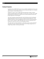
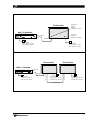
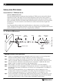
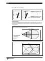
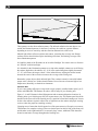
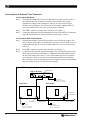
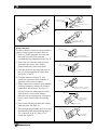
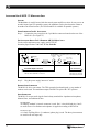
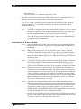
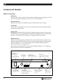
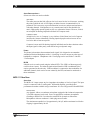
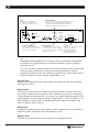
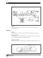
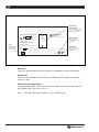
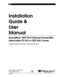
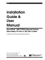
Installation
Guide &
User
Manual
SoundPlus ® WIR TX850 Infrared System,
Selectable 95 kHz or 250 kHz Carrier
Large Area Infrared Listening System
Modulator Model MOD 111
Emitter Model WIR TX8
Receiver Models WIR RX7, RX8
MAN 083D
®
Williams
Sound
Helping People Hear
SOUNDPLUS ® WIR TX850 INFRARED LISTENING SYSTEM,
SELECTABLE 95 KHZ OR 250 KHZ CARRIER
INSTALLATION GUIDE AND USER MANUAL
Contents
Page
SYSTEM OVERVIEW
4
INSTALLATION PROCEDURES
6
STEP 1:
STEP 2:
STEP 3:
STEP 4:
STEP 5:
TX8 EMITTER SETUP
TX8 POWER WIRING
BASEBAND CABLE CONNECTION
MOD 111 MODULATOR SETUP
TESTING THE SYSTEM
CONTROLS AND FEATURES
14
MOD 111 FRONT PANEL
MOD 111 REAR PANEL
TX8 EMITTER PANEL
RECEIVER INSTRUCTIONS
19
TROUBLESHOOTING
21
WARRANTY
22
SPECIFICATIONS
23
NOTE: TAKING A FEW MINUTES NOW TO READ THESE INSTRUCTIONS WILL SAVE TIME AND ENSURE PROPER
SYSTEM OPERATION.
Williams
Sound ®
Helping People Hear
3
SYSTEM OVERVIEW
The Williams Sound WIR TX850 System consists of a MOD 111 Modulator and one or more
TX8 Emitters (also called emitters) which use invisible infrared (IR) light waves to broadcast
speech or music to wireless infrared receivers.
The MOD 111 accepts a variety of audio inputs and sends either a 95 kHz or 250 kHz
frequency modulated signal to the TX8 Emitter via coaxial cable. The emitter emits invisible
infrared light into the listening area. Infrared receivers detect the transmission and convert
the light signals back into audio signals.
The system is designed to transmit high quality audio for hearing assistance and language
translation applications. Because the system uses infrared light for transmission, it is not
affected by interference from radio equipment and does not interfere with radio equipment.
No FCC license is required. A single TX8 Emitter will cover up to 10,000 square feet of
listening area. Larger areas can be covered with additional emitters.
The system can be used with a microphone as a stand-alone system, or can be connected to
an existing sound system. Infrared Systems cannot be used in bright sunlight because of
sunlight’s large amount of interfering infrared light.
4
Williams
Sound ®
Helping People Hear
FIGURE 1: TYPICAL SYSTEM CONFIGURATIONS
Baseband
Present
Indicator
(Visible From Below)
TX8 Transmitter
MOD 111 Modulator
3
2
4 5 6
1
Baseband Out
Phones
7
8 Audio Level
CXR
9
Audio
Infrared
Test Out
Limit
0
10
CH 1 Level
Power
Power On
Indicator
(Visible From Below)
Williams Sound
MOD 111 Selectable 95/250kHz Infrared System Modulator
Compress
Baseband In
Power Supply
120 VAC (US): TFP 016
230 VAC (CE): TFP 027
Power Supply
120 VAC (US): TFP 010
230 VAC (CE): TFP 027
FIGURE 1B: USING AN ADDITIONAL TX8 EMITTER FOR GREATER COVERAGE AREA.
TX8 Transmitter
TX8 Transmitter
MOD 111 Modulator
MOD 111 Selectable 95/250kHz Infrared System Modulator
3
2
1
Power
4 5 6
7
8 Audio Level
CXR
9
0
10
CH 1 Level
Baseband
Out
Williams Sound
Phones
Audio
Limit
Infrared
Test Out
Compress
Power Supply
120 VAC (US): TFP 010
230 VAC (CE): TFP 027
Baseband In
Power Supply
120 VAC (US): TFP 016
230 VAC (CE): TFP 027
Baseband Out
Baseband In
Power Supply
120 VAC (US): TFP 010
230 VAC (CE): TFP 027
Baseband Signal
Williams
Sound ®
Helping People Hear
5
INSTALLATION PROCEDURE
INSTALLATION STEP 1: TX8 EMITTER SET-UP
SELECTING A MOUNTING LOCATION
The most important principle to understand when installing the TX850 system is that invisible infrared
light behaves just like visible light. It does not pass through opaque objects such as walls, curtains, or
people. It does pass through windows and door openings and can bounce and scatter off reflective walls,
floors, and ceilings. Therefore, the infrared emitter panels should not be concealed or covered, nor should
the infrared “eye” on receiver units be covered. Receivers work best with a clear line-of-sight to the
emitter panels.
The TX8 Infrared Emitter should not be installed outdoors, or where there is a lot of direct sunlight
indoors. Sunlight generates infrared interference. Certain types of high-efficiency lighting fixtures can also
generate interference at 95 kHz because they use high frequency modulation.
FIG. 2A: BRACKET 024 MOUNTING
TX8 Emitter
Swivel Head
Shaft
(optional)
Shaft
Plate
Cover
Mounting
Plate
(To Wall or Ceiling)
tension screw
Mounting
Screws
MOUNTING THE TX8 TO A WALL OR CEILING:
Step 1: Using the mounting plate (Figure 2A) as a template, mark the hole locations on the mounting surface
where the TX8 will be installed. See Page 7, Figure 2B for optional mounting positions.
Step 2: Locate the top mounting hole in the rear of the TX8 emitter. Gently screw the male end of the swivel
head on to the emitter. Tighten the swivel head tension screw: turn clockwise until the connection is secure.
Step 3: Screw the male end of the shaft into the female end of the swivel head. An additional shaft can be
added to create more distance between the wall/ceiling and Emitter.
Step 4: Place the plate cover snugly over the mounting plate. This will hide the screws after installation.
Step 5: Screw the male end of the mounting plate into the female end of the shaft. For suspended ceilings, screw
the female end of the shaft into the male end of the T-Bar clip. The mounting bracket is now installed on to
the TX8 Emitter.
Step 6: Position the TX8 Emitter and BKT 024 so the mounting plate lines up with the marked holes on the
mounting surface. Fasten the mounting plate to the surface using screws and wall anchors. Mounting
the TX8 to a Suspended Ceiling with Cross Tee: Fasten the T-Bar clip on to the desired Cross Tee.
Step 7: Position the TX8 Emitter to the desired angle: Begin by gently turning the tension screw (Figure 2A) counter
clockwise to release the swivel head. Adjust the TX8 to the desired angle. When the TX8 is in the desired
position, gently turn the tension screw clockwise until the swivel head is securely in place.
6
Williams
Sound ®
Helping People Hear
FIG. 2B: WALL OR CEILING MOUNT
Figure 2a: Mounting the TX8 on
to a wall with the BKT 024.
Tip: To keep the TX8 level, rotate
the tension screw (Fig. 2A) so it
rests on top of the bracket.
B.
A.
Figure 2b: Mounting the TX8 on
to a ceiling with the BKT 024.
ILLUMINATION PATTERNS
The infrared illumination pattern from a single emitter is cone-shaped, with a 50° angle. The
horizontal and vertical patterns are identical. Figures 3, 4, and 5 show top and side views of
coverage patterns.
FIGURE 3: IR PATTERNS, SINGLE EMITTER INSTALLATION
135 ft.
(41 m)
75 ft.
TX8
(23 m)
25°
25°
Single Channel Mode
Non-reflective
coverage area is
approx. 10,000 sq. ft.
(930 sq. m)
FIGURE 4: MULTIPLE EMITTERS INSTALLED TO MAXIMIZE COVERAGE
Williams
Sound ®
Helping People Hear
TX8
TX8
TX8
TX8
7
FIGURE 5: SIDE PERSPECTIVE
120'
TX8
Center
m
ter Bea
Of Emit
30'
SCREEN
6'
STAGE
These patterns are the direct radiation pattern. The infrared radiation does not drop to zero
outside the illustrated patterns; it decreases. It still may be useable at a greater distance,
depending on receiver sensitivity and the reflection characteristics of the room.
Infrared light reflects off most surfaces and scatters, increasing the coverage area. Rough
surfaces tend to absorb infrared light, minimizing reflections, and limiting coverage to the
direct illumination pattern.
It’s helpful to think of the IR emitter as an invisible floodlight. You want to aim it so listeners
are “flooded” with infrared light.
It’s desirable for the illumination patterns to overlap when multiple emitters are used. Placing
the emitters high above the audience (15–30 ft./4-8 m) and aiming them slightly downward
(5°–15°) will ensure the longest “throw” of the infrared beam. Angling the emitter inward
towards the center of the room also increases the coverage of the seating area.
Remember: opaque objects block infrared light. Thus, emitters cannot be concealed behind
opaque walls, curtains, etc. Neither should emitters be used in areas of extreme high or low
temperatures, humidity, or chemical environments.
COVERAGE AREA
If you’re not getting sufficient coverage with a single, properly installed emitter panel, you’ll
need to add additional TX8 Emitters to achieve full coverage of your listening area.
Figures 3, 4, and 5 illustrate infrared light patterns and recommended emitter locations. In
listening areas up to 10,000 square feet (930 square meters), the TX8 Emitter panel should be
installed on the front wall of the listening area in a position to flood the listening area. It must
be above the audience to permit a direct line of sight between the emitter and people wearing
receivers when the people are standing or sitting.
Listening areas of more than 10,000 square feet (930 square meters) will require two or more
TX8 Emitters for complete coverage. Place one emitter panel on the left side of the front wall
and the other on the right hand side. For extremely large venues, additional TX8s should be
located to maximize coverage throughout the listening area.
8
Williams
Sound ®
Helping People Hear
INSTALLATION STEP 2: TX8 POWER WIRING
FOR U.S. APPLICATIONS:
The TX8 Emitter is supplied with a low-voltage wall transformer power supply
(TFP 010). Two-conductor 18 ga. power cord is included with the emitter.
FOR APPLICATIONS OUTSIDE THE U.S. REQUIRING 240 VAC MAINS SUPPLY:
Use the wall transformer power supply, model TFP 027.
Secondary Specifications: 24 VAC, 35 VA, 50/60 Hz.
!! IMPORTANT WARNING !!
SHORTING THE POWER SUPPLY OUTPUT TERMINALS WILL BLOW A
NON-REPLACEABLE INTERNAL FUSE, DESTROYING THE POWER SUPPLY UNIT!
WARNING: POWERLINE VOLTAGE MUST NOT FALL BELOW 94V, OR
SYSTEM PERFORMANCE WILL BE GREATLY REDUCED.
DO NOT CONNECT THE POWER SUPPLY TO AC POWER YET!!!
Step 1:
Determine the length of power cord needed to reach from the emitter to the AC
wall outlet where the power supply will be plugged in. If power cord length will
exceed 200 feet (61 m), heavier gauge wire will be required. Use the table below.
Make sure the power supply is not plugged into AC power yet!
Cable Length Required
Up to 10 feet (3 m)
Up to 75 feet (23 m)
Up to 200 feet (61 m)
Up to 500 feet (152 m)
Up to 1,000 feet (305 m)
Minimum Wire Gauge
22 gauge
20 gauge
18 gauge
16 gauge
14 gauge
One end of the power cord has a 3-pin Molex connector, the other end is bare. Cut
the bare end of the power cord to length. Strip this end down the middle
approximately
1 inch, then strip both of the resulting strands about 1/8 inch. Install the crimp-on
spade terminals supplied and connect these to the screw terminals on the Power
Supply (TFP 010). Polarity is not important since AC power is being used.
Step 2:
Plug the 3-pin Molex connector into the TX8's Power In connector.
Step 4:
Plug in the Power Supply last.
The Power Indicator LED on the right side of the bottom panel (visible from
directly underneath) glows when the TX8 is on.
The TX8 transmits when an audio signal is present, and will shut off when no
signal is present for about 30 minutes. This auto shut-off feature preserves the life
of the infrared LEDs and reduces power consumption.
Note:
This system is designed for Class 2, low-voltage wiring. Always follow local electrical codes
when doing low voltage wiring.
Williams
Sound ®
Helping People Hear
9
INSTALLATION STEP 3: BASEBAND CABLE CONNECTION
IF YOU ARE USING ONE EMITTER:
Step 1:
Determine the length of RG-58 coaxial cable needed to reach from the emitter to
the modulator unit. The modulator is usually located with the other sound
equipment to simplify audio connections. 100 feet (30 m) of coaxial cable is
included with each emitter. You will need to cut it to length. Additional RG-58
coax can be added. Make sure you leave some slack at each end.
Step 2:
Install BNC connectors on each end of the cable. (See Figure 7.)
Step 3:
Connect the Baseband cable to the Baseband Out jack on the MOD 112 modulator
and to the Baseband In jack on the TX8 Emitter. (See Figures 6 and 8.)
IF YOU ARE USING MORE THAN ONE EMITTER:
Step 1:
Determine the length of coaxial cable needed to reach between the emitters. 100
feet (30 m) of coaxial cable is included with each emitter. You will need to cut it to
length. Additional RG–58 coax can be added. Make sure you leave some slack at
each end.
Step 2:
Install BNC connectors on each end of the cable. (See Figure 7.)
Step 3:
Connect the baseband cable from the Baseband Out Jack on the first emitter in the
chain (the one connected to the MOD 111 Modulator) to the Baseband In jack on
the next TX8 Emitter in the chain. Use the cable clamps and screws provided to
secure the cable. The coax can also be routed through conduit before attaching
BNC connectors. You can chain as many emitters together as you need. Remember
that each emitter needs its own TFP 010 power supply.
FIGURE 6: TX8 EMITTER WIRING DETAIL
MOD 111 Modulator
Audio Input
Baseband Out
Model MOD111 Infrared System Modulator
Williams Sound Corp., Minneapolis, MN USA
Power Supply
120 VAC (US): TFP 016
230 VAC (CE): TFP 027
TX8 Transmitter
TX8 Transmitter
Omnimount
25-STXMP
Omnimount
25-STXMP
Baseband In
Baseband Out
NC
C
24
NC
Power On
24
Power On
Baseband In
Power Supply
120 VAC (US): TFP 010
230 VAC (CE): TFP 027
10
C
To Additional
TX8 Transmitters
Baseband Out
Power Supply
120 VAC (US): TFP 010
230 VAC (CE): TFP 027
Williams
Sound ®
Helping People Hear
7B
FIGURE 7: BNC CONNECTOR ASSEMBLY
Washer
7.92 mm (± .25)
.312 in. (± .01)
Nut
Grooved Side
Gasket (note groove)
Nut
Cable Jacket
Washer
Plug
Assembly
Gasket
7C
Clamp
Contact
Clamp positioned
against Cable Jacket
7D
ASSEMBLY PROCEDURE
Clamp Collar
The BNC Connector consists of a plug assembly, a
contact, a clamp, a gasket, a washer, and a nut.
1. Slide nut, washer and gasket over cable end;
then strip outer cable jacket using the
recommended strip-length dimension in fig. 7b.
Clamp Braid folded
over Clamp and trimmed
7E
2. Slide clamp over cable braid and position it
against the cable jacket. After clamp is
properly positioned, comb out the braid.
3.96 mm (± .25)
.156 in. (± .01)
3. Fold cable braid over the clamp and trim it so
that it is positioned against the clamp collar.
See figures 7c and 7d.
4. Using the dimension in figure 7e, strip
dielectric to expose the center conductor. If
applicable, tin the center conductor.
Dielectric
7F
Dielectric
5. Solder contact to the conductor (using standard
soldering techniques), making sure contact is
bottomed on cable dielectric. See figure 7f.
DO NOT allow a hot soldering iron to touch
cable dielectric. Certain cable dielectric
materials, such as polypropylene, will expand
if they come in contact with a hot soldering
iron.
6. Insert contact into plug assemble until contact
snaps into place. See figure 7g.
7. Thread nut into plug assembly until it is secured.
Recommended cable clamp tightening torque is
2.8–3.4 N•m [25-30 in.-lb.], using a 7/16"
wrench. See figure 7h.
Williams
Sound ®
Helping People Hear
Contact soldered to conductor
and bottomed on dielectric
7G
Gasket (Ref.)
Contact Assembly
inserted into Plug
Assembly
Plug Assembly
7H
50 Ω BNC Plug Connector
Nut Secured Into
Plug Assembly
11
INSTALLATION STEP 4: MOD 111 MODULATOR SETUP
LOCATION
The Modulator is usually located with the sound system amplifier or mixer for easy access to
an audio input signal. For portable systems, the modulator can be placed near the emitter or
in another convenient location. (The SS-6 Stand Kit is available for portable systems.)
POWER CONNECTION FOR U.S. APPLICATIONS:
Step 1:
Connect the power supply to the 3-pin Molex connector located on the rear of the
MOD 111. (See Figure 8.)
FOR APPLICATIONS OUTSIDE THE U.S. REQUIRING 240 VAC MAINS SUPPLY:
Use the wall transformer power supply, model TFP 027.
Secondary Specifications: 24 VAC, 35 VA, 50/60 Hz.
FIGURE 8: MODULATOR WIRING DETAIL
Audio Input
Model MOD111 Infrared System Modulator
Baseband
Output
Balanced
Mic (XLR)
Baseband
Input
Power: 24 VAC,
50-60 Hz, 10VA
Bal or Unbal
Line (1/4")
Channel
(kHz)
Plug
Accessory
Step 2:
50 Ohms
50 Ohms
95
250
Williams Sound Corp., Minneapolis, MN USA
Baseband Output Connection
Power Connection
Connect to TX8 here using
RG-58 cable and BNC connector.
Conect Power Supply
120 VAC (US): TFP 016
230 VAC (CE): TFP 027
Plug the power supply into an AC outlet.
BASEBAND CABLE CONNECTION
The MOD 111 drives one emitter. The TX8 repeats the baseband signal, so any number of
emitters can be used. The modulator outputs CANNOT be split with CATV splitters.
AUDIO CONNECTION
The MOD 112 accepts audio signals from industry-standard low impedance microphones,
balanced lines, and unbalanced lines.
MICROPHONE
An industry standard 3-pin male connector is used. Pin 1 is the shield and pins 2 and 3
are audio. Power for condenser microphones is supplied according to DIN 45596.
BALANCED LINE
A 1/4 inch Tip-Ring-Sleeve (3 conductor) phone plug is used. The three-pin connectors
are used for the mic input only.
12
Williams
Sound ®
Helping People Hear
UNBALANCED LINE
A 1/4 inch Tip-Sleeve (2 conductor) phone plug is used.
8 Ω speaker lines can be connected to the balanced line input. It is usually better NOT to
connect to the sleeve of the plug and thus avoid creating a ground loop.
A 25 V, 70 V, or 100 V speaker line can be connected to the balanced line input using an
appropriate attenuator. “T” pads made with resistors yield better fidelity than speaker
matching transformers.
Note:
The MOD 111 transmits audio with excellent fidelity. Therefore, be sure to connect
its input to a signal source that supply the highest quality audio your system can
offer. The signal should not be processed by an equalizer used for an
accompanying PA system.
The MOD 111 has excellent signal processing, so the use of an additional limiter
or compressor is not recommended.
INSTALLATION STEP 5: TESTING THE SYSTEM
Step 1:
After the baseband cable, power cables, and audio source are connected, turn the
MOD 111 power switch on. The green power LED on the front of the MOD 111
should light.
Step 2:
Make sure the sound system is on and your audio source is active. Adjust the
Audio Level Control. Check the quality of your audio source signal by listening
through the Phones jack on the MOD 111’s front. The MOD 111’s 10-segment bar
graph level indicator shows audio level in 3 dB steps at the input of the audio level
processing circuit.
Step 3:
Look at the TX8 emitter panel(s). With the baseband signal and power connected,
two red lights should be visible from directly underneath the panel: the power
indicator on the right and the baseband indicator on the left. The baseband light
will go off if the modulator carrier goes off–as it will after 30 minutes of no audio.
Step 4:
Hold a receiver near the “Infrared Test Out” LED on the front of the MOD 111.
Turn the receiver on and adjust the volume. You should be able to hear the audio
signal through the receiver. If not, make sure the CXR On Indicator is lit and there
is activity on the Level Indicator. If the lights are not flashing, check your audio
source or the setting of the input level switch and input level control. If the audio
lights are flashing, but you don’t hear anything from the receiver, try a different
receiver to be sure the receiver is working.
Step 5:
Take a receiver into the listening area and walk around to check the reception.
Make sure the emitter and receivers are set to the same frequency. Make sure the
“eye” on the receiver is not covered up when in use. The receiver will not work if
it is placed in a pocket or purse; its eye must be able to “see” the emitter panel.
Williams Sound’s optional WIRM-1 Infrared Field Strength Meter may be used to
check signal strength if the system is operating on 95 kHz.
It may be necessary to adjust the angle of the emitter to obtain the best coverage. If
coverage is not adequate, add one or more WIR TX8 Emitter panels to the system.
(See page 10, If You Are Using More Than One Emitter)
Williams
Sound ®
Helping People Hear
13
CONTROLS AND FEATURES
MOD 111 FRONT PANEL
POWER SWITCH
Turns the entire system on and off. The associated wall mounted power supply stays on at all
times and may operate continuously. There is no “wear out” mechanism.
POWER ON INDICATOR
Indicates actual operation of modulator. Does not indicate status of power supply.
LEVEL CONTROL
Controls level of audio signal. The control is connected between the input amplifier and the
audio level processing circuit.
LEVEL INDICATOR
Bar graph level indicator shows audio level in 3 dB steps at input of audio level processing
circuit. Indicator is peak responding and is calibrated so that optimum level is reached when
the amber +3 light usually blinks and the red +6 light only blinks occasionally.
CXR ON INDICATOR
The Carrier On indicator shows when the carrier is on. The carrier comes on when power is
applied, but goes off automatically if there is no audio for approximately 30 minutes. Audio
sufficient to light the –21 level indicator light will reset the timer, allowing another 30
minutes before the carrier can again go off.
After the carrier has automatically gone off, audio sufficient to light the –21 level indicator
light will turn the carrier back on immediately.
FIGURE 9: MOD 111 FRONT PANEL
Power Switch
Turns the entire system
on and off. The
associated wall
mounted power supply
stays on at all times.
Level Control
Control level of
audio signal.
CXR On Indicator
The Carrier On indicator
shows when the carrier is on.
Phones Jack
The phones jack allows you to
monitor the "as transmitted"
audio.
Williams Sound
MOD 111 Selectable 95/250kHz Infrared System Modulator
4
5
Phones
6
7
3
8
2
9
1
0
Power
Power On Indicator
Indicates actual
operation of unit.
14
Audio Level
-21 -18 -15 -12 -9 -6 -3 0 +3 +6
Audio
CXR
Limit
Infrared
Test Out
10
CH 1 Level
Level Indicator
Bar graph level indicator
shows audio level ijn 3 dB steps
at input of audio level
processing circuit.
Compress
Audio Processor Switch
Selects one of the two
modes: Limit and
Compress
IR LED
Infrared receivers
can be tested
using the IR LED.
Williams
Sound ®
Helping People Hear
AUDIO PROCESSOR SWITCH
Selects one of the two modes available.
LIMIT MODE
The audio processor has little effect on low level sound. As the level increases, reaching
the point at which the red +6 LED lights, no further increase in transmitted level is
permitted. This is necessary to prevent distortion in receivers and prevent interference
with other channels. Limit produces a very natural sound, and is most desirable for
music. High quality speech signals are also very pleasant to listen to. However, Limit is
not as helpful for hearing impaired individuals as Compress mode.
COMPRESS MODE
At high levels, 0 to +6, Compress is very similar to Limit. But at low levels Compress
increases the volume substantially. Hearing impaired people need an increase in low
level to be able to hear most speech.
Compress is most useful for hearing impaired individuals and in those situations where
the input signal is either poorly controlled or has great dynamic range.
PHONES
The phones jack monitors the transmitted audio signal. It is designed to accommodate
standard professional headphones with a 1/4 inch plug. It can also accept any other type of
headphone or earphone. Headphones with 3.5 mm plugs can be used with a 1/4 inch to
3.5 mm adapter.
IR LED
Infrared receivers can be tested using the infrared LED. This LED is of short range only,
useful to about 1 meter. The infrared signal emitted from this LED is modulated by the
carriers generated in this unit only. If this modulator is connected to other modulators for
additional channels, their carriers are not emitted by the LED, and must be monitored at
those modulators.
MOD 111 REAR PANEL
AUDIO INPUT
The MOD 111’s input accepts any low impedance microphone or line level signal. The input
circuit is constructed with a “studio grade” differential amplifier, providing better
performance than that available using a transformer. It is also fully protected from RFI/EMI.
MICROPHONE
Any dynamic, ribbon, or condenser microphone equipped with a balanced output and a
3 pin XLR connector can be used. Power is supplied for condenser microphones
according to DIN 45596. It need not be turned off for dynamic or ribbon mics.
Microphones with two conductor 1/4 inch plugs are not usable.
The minimum acceptable level is approximately 100 µV, and the maximum level before
clipping is approximately 90 mV.
Williams
Sound ®
Helping People Hear
15
FIGURE 10: MOD 111 MODULATOR REAR PANEL
Input
The input to the modulator
accepts any low impedance
microphone or line level signal.
Baseband Output
Carrier tones of 95 kHz and 250 kHz are provided at
this BNC connector. One 50 Ω device may be
connected here using RG-58 cable. Additional
devices may also be connected in series.
Audio Input
Model MOD111 Infrared System Modulator
Baseband
Output
Balanced
Mic (XLR)
Baseband
Input
Power: 24 VAC,
50-60 Hz, 10VA
Bal or Unbal
Line (1/4")
Channel
(kHz)
Plug
Accessory
Accessory Connector
Outputs are available directly
from several points in the internal
circuitry of the modulator.
50 Ohms
50 Ohms
Baseband Input
An additional modulator may be
connected here to allow combining
carriers for more channels. The input
impedance is 50 Ω.
95
250
Williams Sound Corp., Minneapolis, MN USA
Power In
21 VAC to 26 VAC only, 50 or 60 Hz.
120 VAC (US): TFP 010
230 VAC (CE): TFP 027
Current consumption is
approximately 130 mA.
LINE
Both balanced and unbalanced line level signals can be accommodated. The minimum
acceptable level is approximately 100 mV, and the maximum level before clipping is
approximately 10 V.
25 V, 70 V, and 100 V speaker distribution lines can be connected to the Line input using
attenuators made with resistors or with speaker-matching transformers. Resistor
attenuators yield better results. The minimum acceptable level is approximately 100 mV,
and the maximum level before clipping is approximately 10 V.
ACCESSORY INPUT
Outputs are available directly from several points in the internal circuitry of the modulator.
(See Figures 10 and 11.)
BASEBAND OUTPUT
Carrier tones of either 95 kHz or 250 kHz are provided at this BNC connector. One 50 Ω
device may be connected here using RG-58 cable. Additional devices may be connected by
“looping through” the connected device or by means of a suitable distribution amplifier. The
output impedance is 50 Ω. Frequency accuracy is approximately ± .005%. Deviation is ± 50
kHz, maximum. Average deviation is dependent on program material and whether Limit
mode or Compress mode is selected.
BASEBAND INPUT
An additional modulator may be connected here to allow combining carriers for channels in
addition to 95 kHz and 250 kHz. The input impedance is 50 Ω.
FREQUENCY SWITCH
This slide switch selects between carrier frequencies of 95 kHz and 250 kHz.
16
Williams
Sound ®
Helping People Hear
FIGURE 11: MOD 111 CIRCUIT DIAGRAM
OUT AMPL W/DEEMPH
MIC
1
2
COMPRESS
+ 15 V
3
LOW PASS
FILTER
PREEMPHASIS
INPUT
LINE
T
TS
RS
–
LIMIT
LEVEL
DETECTOR
10
LIGHT
BAR
GRAPH
PHONES
CARRIER
SYNTH
CARRIER
TIMER
DEV. CAL.
+
VCO
R
50 µSec
SS
S
95 KHz
VCA
LEVEL
BASEBAND
AMPLIFIER BASEBAND
OUTPUT
250 KHz
1
6
2
7
3
8
4
9
POWER
DIRECT OUT 1
24 VAC
POWER IN
PROCESSED OUT 1
+15 VDC
CIRCUIT COMMON
–15 VDC
CIRCUIT COMMON
+15 VDC
REGULATED
POWER
SUPPLY
3
BASEBAND
COMBINER
INPUT
2
1
CHASSIS
5
ACCESSORY
POWER IN
21 VAC to 26 VAC only, 50 or 60 Hz (TFP 016 Power Supply). Current consumption is
approximately 70 mA.
TX8 EMITTER
POWER INPUT
Three-pin connector for TFP 010 or TFP 027 (for 240 VAC installations) power supply.
POWER INDICATOR LED
Visible through the left side of the bottom panel. Red indicator light glows when power is on.
Note: The TX8 shuts off when no baseband signal is present.
BASEBAND INDICATOR LED
Visible through the left side of the bottom panel. Red indicator light glows when power is on.
FIGURE 12: WIR TX8 BOTTOM PANEL
Power LED
Indicates transmitter is on when lit.
FRONT
BACK
Baseband LED
Indicates presence of baseband signal
Williams
Sound ®
Helping People Hear
17
FIGURE 13: TX8 EMITTER REAR PANEL
Wall/Ceiling
Mount Template
Set of threaded holes
for use with the BKT 024
(Pana-Vise) bracket.
Multi-Channel Infrared Transmitter
Williams
Sound ®
Helping People Hear
CAUTION
RISK OF ELECTRIC SHOCK
DO NOT OPEN
Williams Sound Corp., Minneapolis, Minnesota, USA
Made in U.S.A.
WARNING: TO REDUCE THE RISK OF FIRE OR
ELECTRIC SHOCK DO NOT EXPOSE THIS
EQUIPMENT TO RAIN OR MOISTURE.
Baseband Out
BNC Connector,
50 Ω, 50 kHz–1 MHz
Baseband
Mounting
Template
Note: It is normal for this unit to feel warm while it is in operation.
Power Supply Wiring:
Use NEC, Class 2 Wiring, 18 ga. minimum,
200 ft. (61 m) maximum length (18 ga.)
Power
Connection
Plug in TFP 010
Power Supply
Baseband Signal Wiring:
Use RG58 Coax,1000 ft. (305 m) max. length
Power In:
24VAC
50-60Hz
30W
Plug
Baseband (Modulation)
Out
NC C 24
In
Baseband In
BNC Connector,
50 Ω, 50 kHz–1 MHz
Baseband
50 Ohms
Power On
Baseband On
BASEBAND IN
Connects to the Baseband Out jack of the MOD 111 modulator or another TX8 emitter.
BASEBAND OUT:
Connects to the Baseband In jack of of the next TX8 emitter in the chain when multiple
emitters are used.
SB-3 WALL/CEILING MOUNT TEMPLATE:
A mounting bracket (BKT 024) is included with the emitter. An optional tripod stand kit is
also available (WSC Part #SS-6 or SS-10).
Note:
18
The WIR TX8 Infrared Emitter is a Class 1 LED product.
Williams
Sound ®
Helping People Hear
RECEIVER INSTRUCTIONS
IR RECEIVER MODELS WIR RX7 & WIR RX8
Make sure the “eye” on the front of the receiver is not covered up when in use. The receiver
is intended to be worn on the front of the body, hanging from the lanyard attached to the
receiver. The receiver will not work if it is placed in a pocket or purse. A variety of
earphones, headphones, or neckloop telecoil couplers can be used with both RX7 and RX8
Receivers.
Step 1:
To install the batteries, open the battery compartment using a coin in the slot in the
bottom of the receiver. Press two AA batteries into place, observing proper battery
polarity.
Step 2:
Plug the earphone or headphone into the earphone jack.
Step 3:
Turn the receiver on by rotating the volume control knob clockwise.
Step 4:
Adjust the tone to your preference using the slide switch tone control. To avoid
draining the battery, make sure the receiver is turned off when not in use.
!! IMPORTANT WARNINGS !!
DO NOT ATTEMPT TO RECHARGE ZINC CARBON (“HEAVY DUTY”), ALKALINE, OR
LITHIUM BATTERIES!
DO NOT ATTEMPT TO RECHARGE SINGLE-USE BATTERIES! These batteries may heat up
and explode, causing possible injury and damage to the equipment.
Avoid shorting the plus and minus battery terminals together with metal objects. Battery
damage and burns can result!
Use only Williams Sound supplied chargers and batteries!
BATTERY INFORMATION
For RX7 and RX8 Receivers in normal use, two AA alkaline batteries (BAT 001) will last
about 30 hours. Rechargeable AA batteries (BAT 026) will last about 15 hours per charge.
If you are using BAT 026 rechargeable batteries, use the CHG 200A Multi-Charger. Contact
your dealer or Williams Sound for details.
If the sound becomes weak or distorted, replace the batteries. The indicator light may still be
on, even with weak batteries. Do not leave dead batteries in the receiver, they may leak and
damage the receiver.
Williams
Sound ®
Helping People Hear
19
RECEIVER MANAGEMENT
Different types of facilities will use different approaches for receiver management and
earphone sanitation. Below are some options that customers have used successfully.
20
Regular users purchase their own receiver and take care of their own batteries and
earphone.
Some facilities label the receiver and earphone with the names of regular users so each
person uses the same receiver and earphone.
Ushers issue receivers to people who request them. Earphones are sanitized after use.
Foam ear cushions can be replaced or washed with a mild detergent, rinsed thoroughly
and air-dried. The EAR 022 Surround Earphone can be sanitized with an alcohol pad.
The receivers can be stored in a multiple compartment storage case with a credit card or
driver's license left as collateral for the receiver.
Regular users purchase their own earphone or headphone and bring them to use with
receivers at the facility.
Some facilities use the drop-in style CHG 200 Multi-charger for both storing and
charging receivers.
Williams
Sound ®
Helping People Hear
TROUBLESHOOTING
NEITHER TX8 INDICATOR LIGHT IS ON (FIGURES 1A AND 13).
Make sure the wall transformer is plugged into the emitter and the power switch or any
remote power switch is on.
Make sure the electrical outlet is on.
Make sure the 24 VAC power supplies are working.
ONLY TX8’S POWER INDICATOR LED COMES ON (FIGURES 1A AND 13).
Make sure the MOD 111 is on.
Make sure the baseband cable is connected properly.
Check to see if the carrier light on the MOD 111 is on.
Make sure an audio signal is being sent to the MOD 111.
NO SOUND THROUGH RECEIVERS.
If some of the receivers work but others don’t, check for bad batteries or earphones on
the receivers that aren’t working.
If none of the receivers work, check to see if the power and baseband cable are
connected to the emitter and that the Power and Baseband Indicator lights are ON.
Check to see if the modulator is connected properly to the sound system. The CXR On
Indicator should be lit and there should be activity on the MOD 111’s Level Indicators.
Make sure the “eye” is not covered up on the receiver. There must be clear line of sight
between the receiver eye and the emitter panel.
Make sure the selected modulator frequency matches the selected receiver frequency.
SOUND THROUGH THE RECEIVERS IS WEAK AND NOISY.
Hold a receiver in front of the Infrared Test LED on the front of the MOD 111 modulator
and listen to the signal. If the signal is weak and noisy here, check the Input Level switch
and Input Level Control settings. Increase the input signal level from the sound system
by turning up a mixer control. If the signal sounds okay, you may need to re-position the
emitter panels or add additional panels.
NOTE: Make sure the powerline voltage does not fall below 94V, or system
performance will be greatly reduced!
BUZZING OR HUMMING NOISE IN SOUND SYSTEM.
Check for ground loops or noise on the input signal. Call your Authorized Dealer or
Williams Sound for help.
Williams
Sound ®
Helping People Hear
21
WARRANTY
Williams Sound infrared modulators, emitters and receivers are warranted against defects in
workmanship and materials for FIVE YEARS. Microphones, earphones, cables, carry cases,
rechargeable batteries and chargers are warranted against defects in workmanship and
materials for 90 DAYS.
This warranty does not extend to intentional or accidental physical damage. This warranty
applies only to products returned to Williams Sound for service. To return a product for
service, call the phone number below and request a Return Authorization (RA) number.
Williams Sound Corp.
10399 West 70th Street
Eden Prairie, MN 55344-3459 USA
Phone: 800-843-3544
952-943-2252
22
Fax:
952-943-2174
TTY:
952-943-9675
Web:
www.williamssound.com
[email protected]
Williams
Sound ®
Helping People Hear
SoundPlus® WIR TX850 Infrared System Specifications
SELECTABLE CHANNEL INFRARED MODULATOR, MODEL MOD 111
Dimensions, Weight:
8.45" (21.5 cm) W x 8.18" (20.8 cm) D x 1.72" (4.4 cm) H, 3 lbs. (1.5 kg)
Color:
Black epoxy paint with white legends
Rack Mount:
One IEC rack space high, one or two units can be mounted in a single rack space with
optional RPK 005 (single) or RPK 006 (double) Rack Mount Kits
Power:
External power supply, 24VAC, 50 or 60Hz, 10 VA maximum
Baseband Output:
50 Ω source impedance
Carrier:
100 mV
Frequency:
95 kHz or 250 kHz; ± 50 kHz deviation, 50 µsec pre-emphasis
AGC:
Variable slope compressor or soft limiter, switch selected
Carrier Timer:
One 30 minute (approx.) timer. Turns off carrier if channel is silent (lowest light on bar
graph does not light) for approximately 30 minutes.
Operating Req.:
0-50°C ambient temperature, non-condensing, non-corrosive atmosphere
FRONT PANEL:
Power Switch:
Two-position rocker, ON/OFF
Power Indicator:
Green LED
Audio Level Control:
1 control
Audio Indicator:
One (1) 10 LED bar graph
Carrier LED:
1 carrier on indicator LED, green
Limit/Compress Switch:
Selects variable slope compression or soft limiting
Phones Output:
1/4" stereo phones jack. Produces mono output.
Accepts stereo or mono phones, any impedance
Infrared Test LED:
IR LED for receiver testing, monitoring, and audio signal testing.
Effective to about 1 meter from front panel
REAR PANEL:
Line Input (Floating):
1/4" TRS jack. Accepts unbalanced or balanced line level inputs
Mic Input:
lo-Z, 100 µV min. to 90 mV max. 1 mV nominal, 3 kΩ input impedance
Supplies simplex power 15 V (DIN45596) for condenser mics
Baseband Output:
(1) BNC connector, 50 Ω, 100 mV RMS per carrier, use RG-58 cable
Baseband Loopthru Input:
(1) BNC connector, 50 Ω
Power Connections:
3-pin molex
Emitter Type:
For use with Williams Sound Infrared Emitters. For multi-emitter systems, each emitter
repeats the baseband signal to drive the next emitter in the chain.
Accessory Connector:
9-pin, D-Sub female, various circuit connections
(See diagram on top panel for details)
Note:
Infrared receiver performance can be degraded if this system is used in close proximity to
high-efficiency lighting equipment with solid state ballasts (i.e. high efficiency fluorescent)
that operate at frequencies near 95 kHz. 250 kHz operation should be used when this
occurs.
MULTI-CHANNEL INFRARED EMITTER, MODEL TX8
Dimensions, Weight:
11.25" W x 6.25" H x 2.125" D (28.6 cm x 15.9 cm x 5.4 cm) 1.9 lbs. (0.9 kg)
Color:
Black epoxy paint with white legends, red acrylic window
Wall Mount:
BKT 024 mounting bracket included for wall and ceiling mounting.
Tripod Mount:
Optional SS-6 Tripod Stand Kit available
Power:
External power supply, 24 VAC, 50 or 60 Hz, 50 VA, 0.9 A nom. current drain
Emitter shuts off when baseband signal is not present
Operating Req.:
0-50° C ambient temperature, non-condensing, non-corrosive atmosphere
Coverage Area:
Two-Channel mode: 3,760 sq. ft. (350 sq. m) Single-Channel mode: 10,000 sq. ft. (930 sq. m)
50° cone pattern, see coverage diagrams
Class 1 LED Product
Infrared Type:
Williams
Sound ®
Helping People Hear
23
FRONT PANEL:
Power Indicator:
Red LED, visible from bottom through vent holes, lower right
Baseband Indicator:
Red LED, visible from bottom through vent holes, lower left
REAR PANEL:
Mounting Holes:
One set of threaded holes for use with the BKT 024 mounting bracket (included)
Two threaded holes on sides of the cabinet for Tripod Stand Kit
Baseband Input:
BNC connector, 50 Ω, 50 kHz to 500 kHz carriers, 100 mV nominal per carrier,
10 V RMS maximum aggregate baseband amplitude
Baseband Output:
BNC connector, 50 Ω, 50 kHz to kHz baseband
Baseband Cable:
RG-58 Coax, BNC-connectors
Power:
External power supply, 3-pin molex connector, 24 VAC, 50 or 60 Hz, 30 VA, 0.9 A nom.
current drain
Power Cable:
NEC Class 2 wiring, 2-conductor, 18 ga.; 200 foot (61 m) max. length for 18 gauge wire
(See table below for minimum gauge requirements at other lengths)
Each TX8 Transmitter requires its own 24 VAC Power Supply
Cable Length Required
0–
10 feet (3 m)
0–
75 feet (23 m)
0–
200 feet (61 m)
0–
500 feet (152 m)
0 – 1,000 feet (305 m)
Minimum Wire Gauge
22 gauge
20 gauge
18 gauge
16 gauge
14 gauge
INFRARED RECEIVER, MODEL WIR RX7
Size and Weight:
3-5/8" L x 2-3/8" W x 7/8" H (9.2 cm x 6 cm x 2.4 cm) 4.48 oz. (127 g)
Color and Material:
Neptune Blue, shatter-proof polypropylene
Battery Type:
1.5V (AA) x 2, Alkaline (BAT 001) or Rechargeable AA NiMH (BAT 026)
Battery Life:
30 hours with BAT 001, 15 hours/charge with BAT 026, 25 mA, nom. current drain
Modulation Frequency:
250 kHz FM, 50 µS de-emphasis
Signal to Noise Ratio:
60 dB with WIR TX8 and MOD 111
Controls:
Combination volume/On-Off knob,
Switched Low-Cut tone control (Lo: 20 Hz / Mid: 120 Hz / Hi: 700 Hz)
Audio Output:
3.5 mm mono mini phone jack, 35 mW maximum into 16 Ω
Acoustic Output:
130 dB MAX SSPL90 with EAR 013
Note:
The RX7/RX8 Infrared Receivers can be used with a Neckloop TeleCoil Coupler
(NKL 001) to magnetically couple into a hearing aid that has a telephone pick-up coil.
Add’l Compatible Receivers:
WIR RX8:
WIR RX5:
Single Channel Infrared Receiver, operates at 95 kHz
Selectable Channel Infrared Receiver, operates at either 95 kHz or 250 kHz
ACCESSORIES
CHG 200 Multi-Charger
This charger is designed to store and charge one or two receivers simultaneously
overnight. 110 VAC
SS-6 Tripod Stand Kit
Includes adjustable tripod stand, adaptor, mounting bracket, and hardware. Mounts
modulator and emitter together or separately.
RPK 005/RPK 006 Rack Panel Kits
The RPK 005 mounts one modulator in one EIA rack space, the RPK 006 mounts two.
Includes all necessary hardware and easy-to-follow instructions.
Williams Sound Corp.
10399 West 70th St., Eden Prairie, MN 55344-3459
U.S.A. 800-328-6190 / 952-943-2252 / FAX: 952-943-2174
www.williamssound.com
© 2003, Williams Sound Corp.
MAN 083D