1
France
Draft proposal
ELSA-7-04
REGULATION 95 CONCERNING THE APPROVAL OF VEHICLES WITH
REGARD TO THE PROTECTION OF THE OCCUPANTS IN THE EVENT OF A
LATERAL COLLISION
Regulation 95
AGREEMENT
CONCERNING THE ADOPTION OF UNIFORM TECHNICAL PRESCRIPTION FOR
WHEELED VEHICLES, EQUIPMENT AND PARTS WHICH CAN BE FITTED
AND/OR BE USED ON WHEELED VEHICLES AND THE CONDITIONS FOR
RECIPROCAL RECOGNITION OF APPROVALS GRANTED ON THE BASIS OF
THESE PRESCRIPTIONS */
(Revision 2, including the amendments entered into force on 16 October 1995)
_____________
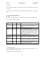
Addendum 94: Regulation No. 95
Date of entry into force: 6 July 1995
Incorporating Correction - Date of entry into force: 10 March 1995
Amendment 1
01 series of amendments - Date of entry into force: 12 August 1998
Amendment 2
Supplement 1 to the 01 series of amendments - Date of entry into force: 14 November
1999
Corrigendum 1
Corrigendum 3 to the original version of the Regulation, subject of Depositary
Notification C.N.786.2002.TREATIES-1 dated 1 August 2002
Amendment 3
02 series of amendments - Date of entry into force: 16 July 2003
Amendment 4
Supplement 1 to the 02 series of amendments - Date of entry into force: 12 August 2004
Corrigendum 1 to Supplement 1 to the 02 series of amendments, subject of Depositary
Notification C.N.1167.2007.TREATIES-2 dated 18 January 2008
Page 1
France
Draft proposal
ELSA-7-04
UNIFORM PROVISIONS CONCERNING THE
APPROVAL OF VEHICLES WITH REGARD TO
THE PROTECTION OF THE OCCUPANTS IN THE
EVENT OF A LATERAL COLLISION
Regulation No. 95
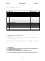
1. SCOPE
This Regulation applies to the lateral collision behaviour of the structure of the passenger
compartment of M1 and N1 categories of vehicles where the R point of the lowest seat is
not more than 700 mm from ground level when the vehicle is in the condition
corresponding to the reference mass defined in paragraph 2.10. of this Regulation.
2. DEFINITIONS
For the purposes of this Regulation:
2.1. "Approval of a vehicle"
means the approval of a vehicle type with regard to the behaviour of the structure of the
passenger compartment in a lateral collision;
2.2. "Vehicle type"
means a category of power-driven vehicles which do not differ in such essential respects
as:
2.2.1. the length, width and ground clearance of the vehicle, in so far as they have a
Page 2
France
Draft proposal
ELSA-7-04
negative effect on the performance prescribed in this Regulation;
2.2.2. the structure, dimensions, lines and materials of the side walls of the passenger
compartment in so far as they have a negative effect on the performance prescribed in
this Regulation;
2.2.3. the lines and inside dimensions of the passenger compartment and the type of
protective systems, in so far as they have a negative effect on the performance prescribed
in this Regulation;
2.2.4. the siting of the engine (front, rear or centre);
2.2.5. the unladen mass, in so far as there is a negative effect on the performance
prescribed in this Regulation;
2.2.6. the optional arrangements or interior fittings in so far as they have a negative effect
on the performance prescribed in this Regulation;
2.2.7. the type of front seat(s) and position of the "R" point in so far as they have a
negative effect on the performance prescribed in this Regulation;
2.2.8. The place of the RESS.
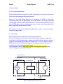
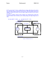
2.3. “Compartment”means bounded zone in vehicle,
2.3.1. "Passenger compartment"
means the space for occupant accommodation, bounded by the roof, floor, side walls,
doors, outside glazing and front bulkhead and the plane of the rear compartment bulkhead
or the plane of the rear-seat back support; or rear gate, as well as by the barriers and
enclosures provided for protecting the power train from direct contact with live parts.
2.3.2. Luggage compartment means the space in the vehicle for luggage
accommodation, bounded by the roof, hood, floor, side walls, as well as by the barrier
and enclosure. For electric vehicles, hybrid vehicles and fuel cell vehicles the barrier
and enclosure are provided for protecting the power train from direct contact with live
parts, being separated from the passenger compartment by the front bulkhead or the
rear bulk head,
2.4. "R point" or "seating reference point"
means the reference point specified by the vehicle manufacturer which:
2.4.1. has co-ordinates determined in relation to the vehicle structure;
2.4.2. corresponds to the theoretical position of the point of torso/thighs rotation (H point)
for the lowest and most rearward normal driving position or position of use given by the
Page 3
France
Draft proposal
ELSA-7-04
vehicle manufacturer for each seating position specified by him;
2.5. "H point" is as established by annex 3 to this Regulation;
2.6. "Capacity of the fuel tank"
means the fuel-tank capacity as specified by the manufacturer of the vehicle;
2.7. "Transverse plane"
means a vertical plane perpendicular to the median longitudinal vertical plane of the
vehicle;
2.8. "Protective system"
means devices intended to restrain and/or protect the occupants;
2.9. "Type of protective system"
means a category of protective devices which do not differ in such essential respects as
their:
technology
geometry
constituent materials;
2.10. "Reference mass"
means the unladen mass of the vehicle increased by a mass of 100 kg (that is the mass of
the side impact dummy and its instrumentation);
2.11. "Unladen mass"
means the mass of the vehicle in running order without driver, passengers or load, but
with the fuel tank filled to 90 per cent of its capacity and the usual set of tools and spare
wheel on board, where applicable;
2.12. "Mobile deformable barrier"
means the apparatus with which the test vehicle is impacted. It consists of a trolley and an
impactor;
2.13. "Impactor"
means a crushable section mounted on the front of mobile deformable barrier;
2.14. "Trolley"
means a wheeled frame free to travel along its longitudinal axis at the point of impact. Its
front supports the impactor.
2.15. “Electric power train”
means the electrical circuit which may include the RESS, the energy conversion system,
the electronic converters, the traction motors, the associated wiring harness and
Page 4
France
Draft proposal
ELSA-7-04
connectors, and the coupling system for charging the RESS,
2.16. “RESS” means rechargeable energy storage system that provides the electric
energy for propulsion,
2.17. “Energy conversion system” means system that generates and provides electric
energy for propulsion,
2.18. “Electronic converter” means a device capable of controlling or converting
electric power,
2.19. “Coupling system for charging the RESS” means the electrical circuit used for
charging the RESS from an external electric power supply (AC or DC electric
power supply outside of the vehicle) including the vehicle inlet,
2.20. “Direct contact” means the contact of persons with live parts,
2.21. “Live parts” means conductive part(s) intended to be electrically energized in
normal use,
2.22. “Indirect contact” means the contact of persons with exposed conductive parts,
2.23. “Protection degree” means Protection provided by a barrier/enclosure related to
the contact with live parts by a test probe, such as a test finger (IPXXB), or a test
wire (IPXXD),
2.24. “Exposed conductive part” means conductive part which can be touched, and
which only becomes electrically energized under failure conditions,
2.25. “Electrical circuit” means an assembly of connected live parts which is designed
to be electrically energized in normal operation,
2.26. “Working voltage” means he highest value of an electrical circuit voltage,
specified by the manufacturer, which may occur between any conductive parts in
open circuit conditions or under normal operating conditions,
2.27. “Electrical chassis” means a set made of conductive parts electrically linked
together, whose potential is taken as reference,
2.28. “Solid insulator” means insulating coating of wiring harnesses provided in order
to cover and protect the live parts against direct contact from any direction of
access; covers for insulating the live parts of connectors; and varnish or paint for
the purpose of insulation,
2.29. “Barrier” means the part providing protection against direct contact to the live
parts from any direction of access,
Page 5
France
Draft proposal
ELSA-7-04
2.30. “Enclosure” means the part enclosing the internal units and providing protection
against direct contact from any direction of access,
2.31. “High Voltage” means classification of an electric component or circuit, if its
maximum working voltage is > 60 V and ≤ [1500] V d.c. or > 30 V and ≤ [1000] V
a.c.
2.32. “High Voltage Bus” means electrical circuit, including the coupling system for
charging the RESS, that operates on high voltage
3. APPLICATION FOR APPROVAL
3.1. The application for approval of a vehicle type with regard to the protection of the
occupants in the event of a lateral collision shall be submitted by the vehicle
manufacturer or by his duly accredited representative.
3.2. It shall be accompanied by the under mentioned documents in triplicate and the
following particulars:
3.2.1. a detailed description of the vehicle type with respect to its structure, dimensions,
lines and constituent materials;
3.2.2. photographs and/or diagrams and drawings of the vehicle showing the vehicle type
in front, side and rear elevation and design details of the lateral part of the structure;
3.2.3. particulars of the vehicle's mass as defined by paragraph 2.11. of this Regulation;
3.2.4. the lines and inside dimensions of the passenger compartment;
3.2.5. a description of the relevant side interior fittings and protective systems installed in
the vehicle.
3.3. The applicant for approval shall be entitled to present any data and results of tests
carried out which make it possible to establish that compliance with the requirements can
be achieved on prototype vehicles with a sufficient degree of accuracy.
3.4. A vehicle which is representative of the type to be approved shall be submitted to the
technical service responsible for conducting the approval tests.
3.4.1. A vehicle not comprising all the components proper to the type may be accepted
for tests provided that it can be shown that the absence of the components omitted has no
detrimental effect on the performance prescribed in the requirements of this Regulation.
3.4.2. It shall be the responsibility of the applicant for approval to show that the
application of paragraph 3.4.1. is in compliance with the requirements of this Regulation.
Page 6
France
Draft proposal
ELSA-7-04
4. APPROVAL
4.1. If the vehicle type submitted for approval pursuant to this Regulation meets the
requirements of paragraph 5 below, approval of that vehicle type shall be granted.
4.2. In case of doubt, account shall be taken, when verifying the conformity of the vehicle
to the requirements of this Regulation, of any data or test results provided by the
manufacturer which can be taken into consideration in validating the approval test carried
out by the technical service.
4.3. An approval number shall be assigned to each type approved. Its first two digits (at
present 01 corresponding to the 01 series of amendments) shall indicate the series of
amendments incorporating the most recent major technical amendments made to the
Regulation at the time of issue of the approval. The same Contracting Party may not
assign the same approval number to another vehicle type.
4.4. Notice of approval or of extension or of refusal of approval of a vehicle type
pursuant to this Regulation shall be communicated by the Parties to the Agreement
applying this Regulation by means of a form conforming to the model in annex 1 to this
Regulation and photographs and/or diagrams and drawings supplied by the applicant for
approval, in a format not exceeding A4 (210 x 297) mm or folded to that format and on
an appropriate scale.
4.5. There shall be affixed to every vehicle conforming to a vehicle type approved under
this Regulation, conspicuously and in a readily accessible place specified on the approval
form, an international approval mark consisting of:
4.5.1. a circle surrounding the letter "E" followed by the distinguishing number of the
country which has granted approval; 1/
4.5.2. the number of this Regulation, followed by the letter "R", a dash and the approval
number, to the right of the circle prescribed in paragraph 4.5.1.
4.6. If the vehicle conforms to a vehicle type approved, under one or more other
Regulations annexed to the Agreement, in the country which has granted approval under
this Regulation, the symbol prescribed in paragraph 4.5.1. need not be repeated; in this
case the Regulation and approval numbers and the additional symbols of all the
Regulations under which approval has been granted in the country which has granted
approval under this Regulation shall be placed in vertical columns to the right of the
symbol prescribed in paragraph 4.5.1.
4.7. The approval mark shall be clearly legible and shall be indelible.
4.8. The approval mark shall be placed close to or on the vehicle data plate affixed by the
manufacturer.
4.9. Annex 2 to this Regulation gives examples of approval marks.
Page 7
France
Draft proposal
ELSA-7-04
5. SPECIFICATIONS AND TESTS
5.1. The vehicle shall undergo a test in accordance with annex 4 to this Regulation.
5.1.1. The test will be carried out on the driver's side unless asymmetric side structures, if
any, are so different as to affect the performance in a side impact. In that case either of
the alternatives in paragraph 5.1.1.1. or5.1.1.2. may be used by agreement between the
manufacturer and test authority.
5.1.1.1. The manufacturer will provide the authority responsible for approval with
information regarding the compatibility of performances in comparison with the driver's
side when the test is being carried out on that side.
5.1.1.2. The approval authority, if concerned as to the construction of the vehicle, will
decide to have the test performed on the side opposite the driver, this being considered
the least favourable.
5.1.2. The Technical Service, after consultation with the manufacturer, may require the
test to be carried out with the seat in a position other than the one indicated in paragraph
5.5.1. of annex 4. This position shall be indicated in the test report. 2/
5.1.3. The result of this test shall be considered satisfactory if the conditions set out in
paragraphs 5.2. and 5.4. below are satisfied.
5.2. Performance criteria
5.2.1. The performance criteria, as determined for the collision test in accordance with
the appendix to annex 4 to this Regulation shall meet the following conditions:
5.2.1.1. the head performance criterion (HPC) shall be less than or equal to 1,000; when
there is no head contact, then the HPC shall not be measured or calculated but recorded
as "No Head Contact."
5.2.1.2. the thorax performance criteria shall be:
(a) Rib Deflection Criterion (RDC) less than or equal to 42 mm;
(b) Soft Tissue Criterion (VC) less or equal to 1.0 m/sec.
For a transitional period of two years after the date specified in paragraph 10.2. of this
Regulation the V * C value is not a pass/fail criterion for the approval testing, but this
value has to be recorded in the test report and to be collected by the approval authorities.
After this transitional period, the VC value of 1.0 m/sec shall apply as a pass/fail criterion
unless the Contracting Parties applying this Regulation decide otherwise.
5.2.1.3. the pelvis performance criterion shall be:
Pubic Symphysis Peak Force (PSPF) less than or equal to 6 kN.
Page 8
France
Draft proposal
ELSA-7-04
5.2.1.4. the abdomen performance criterion shall be:
Abdominal Peak Force (APF) less than or equal to 2.5 kN internal force (equivalent to
external force of 4.5 kN).
5.3. Particular requirements
5.3.1. No door shall open during the test.
5.3.2. After the impact, it shall be possible without the use of tools to:
5.3.2.1. open a sufficient number of doors provided for normal entry and exit of
passengers and if necessary tilt the seat-backs or seats to allow evacuation of all
occupants;
5.3.2.2. release the dummy from the protective system;
5.3.2.3. remove the dummy from the vehicle;
5.3.3. no interior device or component shall become detached in such a way as noticeably
to increase the risk of injury from sharp projections or jagged edges;
5.3.4. ruptures, resulting from permanent deformation are acceptable, provided these do
not increase the risk of injury;
5.3.5. if there is continuous leakage of liquid from the fuel-feed installation after the
collision, the rate of leakage shall not exceed 30 g/min; if the liquid from the fuel-feed
system mixes with liquids from the other systems and the various liquids cannot easily be
separated and identified, all the liquids collected shall be taken into account in evaluating
the continuous leakage.
5.4.This requirements are apply to the electric power train of electric vehicles, hybrid
vehicles and fuel cell vehicles, and the high voltage components and systems which are
galvanically connected to the high voltage bus of the electric power train following
vehicle crash test(s).
5.4.1.Not more than 5.0 liters of electrolyte from propulsion batteries shall spill outside
the passenger compartment, and no visible trace of electrolyte shall spill into the
passenger compartment, within 30 minutes after a barrier impact test. Compliance may
be demonstrated by test or analysis.
5.4.2.Battery modules located inside the passenger compartment must remain in the
location in which they are installed. No part of any battery system component that is
located outside the passenger compartment shall enter the passenger compartment
during the test procedures, as determined by visual inspection.
Page 9
France
Draft proposal
ELSA-7-04
5.4.3.After the test, at least one of the following criteria specified in paragraph 5.4.3.1
thorough paragraph 5.4.3.4 shall be met. If the vehicle has an automatic disconnect
function, the criteria shall be applied to each divided portion individually
5.4.3.1.Isolation Resistance: If the electrical circuit divided by the disconnect function
includes AC circuit, this part of the high voltage bus shall be considered as an AC high
voltage bus. If the electrical circuit divided by the disconnect function doesn't include
AC circuit, this part of the high voltage bus shall be considered as a DC high voltage
bus.
For AC high voltage buses, isolation resistance between the high voltage bus
and the electrical chassis shall have minimum value of 500 ohms/volt of working
voltage. If the protection degree IPXXB is satisfied for AC portion of the high voltage
buses after crash, isolation resistance between the high voltage bus and the electrical
chassis shall have minimum value of 100 ohms/volt of working voltage.
For DC high voltage buses, isolation resistance between any high voltage bus
and the electrical chassis shall have minimum value of 100 ohms/volt of working
voltage.
5.4.3.2.Voltage: For AC high voltage buses, voltage of the bus shall be equal to or less
than 30 VAC. For DC high voltage buses, voltage of the bus shall be equal to or less
than 60 VDC
5.4.3.3.Energy: Energy on the high voltage bus shall be less than 0.2 Joules.
5.4.3.4.Physical Protection: For protection of live parts, the protection degree IPXXB
shall be provided.
For protection against indirect contact with live parts, all exposed conductive parts
electro shall be securely connected to the electrical chassis such that no dangerous
potentials are produced.
The resistance between the electrical chassis and all conductive parts shall be less than
0.1 ohm, which is measured when there is a current flow of at least 0.2 amps.
The said resistance shall be regarded as lower than 0.1 ohm when it is clearly evident
that the DC electrical connection has been established adequately and securely by
welding.
6. MODIFICATION OF THE VEHICLE TYPE
6.1. Any modification affecting the structure, the number and type of seats, the interior
trim or fittings, or the position of the vehicle controls or of mechanical parts which might
affect the energy-absorption capacity of the side of the vehicle, shall be brought to the
notice of the administrative department granting approval. The department may then
either:
Page 10
France
Draft proposal
ELSA-7-04
6.1.1. consider that the modifications made are unlikely to have an appreciable adverse
effect and that in any case the vehicle still complies with the requirements, or
6.1.2. require a further test report from the technical service responsible for conducting
the tests;
6.1.2.1. Any modification of the vehicle affecting the general form of the structure of the
vehicle or any variation in the reference mass greater than 8 per cent which in the
judgement of the authority would have a marked influence on the results of the test shall
require a repetition of the test as described in annex 4.
6.1.2.2. If the technical service, after consultation with the vehicle manufacturer,
considers that modifications to a vehicle type are insufficient to warrant a complete retest
then a partial test may be used. This would be the case if the reference mass is not more
than 8 per cent different from the original vehicle or the number of front seats is
unchanged. Variations of seat type or interior fittings need not automatically entail a full
retest. An example of the approach to this problem is given in annex 8.
6.2. Confirmation or refusal of approval, specifying the alteration, shall be communicated
by the procedure specified in paragraph 4.4. above to the Parties to the Agreement which
apply this Regulation.
6.3. The competent authority issuing an extension of approval shall assign a series
number to each communication form drawn up for such an extension.
7. CONFORMITY OF PRODUCTION
The conformity of production procedures shall comply with those set out in the
Agreement, Appendix 2 (E/ECE/324-E/ECE/TRANS/505/Rev.2), with the following
requirements:
7.1. Every vehicle approved under this Regulation shall be so manufactured as to
conform to the type approved by meeting the requirements set out in paragraph 5 above.
7.2. The holder of the approval shall ensure that for each type of vehicle at least the tests
concerning the taking of measurements are carried out.
7.3. The authority which has granted type approval may at any time verify the conformity
control methods applied in each production facility. The normal frequency of these
verifications shall be once every two years.
8. PENALTIES FOR NON-CONFORMITY OF PRODUCTION
8.1. The approval granted in respect of a vehicle type, pursuant to this Regulation, may
Page 11
France
Draft proposal
ELSA-7-04
be withdrawn if the requirement laid down in paragraph 7.1. above is not complied with,
or if the vehicle or vehicles selected have failed to pass the checks prescribed in
paragraph 7.2. above.
8.2. If a Contracting Party to the Agreement applying this Regulation withdraws an
approval it has previously granted, it shall forthwith so notify the other Contracting
Parties applying this Regulation by means of a communication form conforming to the
model in annex 1 to this Regulation.
9. PRODUCTION DEFINITELY DISCONTINUED
If the holder of the approval completely ceases to manufacture a type of vehicle approved
in accordance with this Regulation, he shall so inform the authority which granted the
approval. Upon receiving the relevant communication that authority shall inform thereof
the other Parties to the 1958 Agreement applying this Regulation by means of a
communication form conforming to the model in annex 1 to this Regulation.
10. TRANSITIONAL PROVISIONS
10.1. As from the official date of entry into force of Supplement 1 to the 02 series of
amendments, no Contracting Party applying this Regulation shall refuse to grant ECE
approval under this Regulation as amended by Supplement 1 to the 02 series of
amendments.
10.2. As from 12 months after the entry into force of the 02 series of amendments,
Contracting Parties applying this Regulation shall grant ECE approvals only to those
types of vehicles which comply with the requirements of this Regulation as amended by
the 02 series of amendments.
10.3. As from 60 months after the entry into force of the 02 series of amendments,
Contracting Parties applying this Regulation may refuse first national registration (first
entry into service) of vehicles which do not meet the requirements of this Regulation as
amended by the 02 series of amendments.
10.4. As from 36 months after the entry into force of Supplement 1 to the 02 series of
amendments Contracting Parties applying this Regulation shall grant ECE approvals only
to those types of vehicles which comply with the requirements of this Regulation. as
amended by Supplement 1 to the 02 series of amendments.
10.5. As from 84 months after the entry into force of Supplement 1 to the 02 series of
amendments Contracting Parties applying this Regulation may refuse first national
registration (first entry into service) of vehicles which do not meet the requirements of
this regulation as amended by Supplement 1 to the 02 series of amendments."
Page 12
France
Draft proposal
ELSA-7-04
11. TRANSITIONAL PROVISIONS
11.1. As from the official date of entry into force of the 02 series of amendments, no
Contracting Party applying this Regulation shall refuse to grant ECE approval under this
Regulation as amended by the 02 series of amendments.
11.2. As from 12 months after the entry into force of the 02 series of amendments
Contracting Parties applying this Regulation shall grant ECE approvals only to those
types of vehicles which comply with the requirements of this Regulation as amended by
the 02 series of amendments.
11.3. As from 60 months after the entry into service of the 02 series of amendments
Contracting Parties applying this Regulation may refuse first national registration (first
entry into service) of vehicles which do not meet the requirements of this Regulation as
amended by the 02 series of amendments."
Annex 1
COMMUNICATION
(maximum format: A4 (210 x 297 mm))
1/
issued by: Name of administration:
.......................................
.......................................
.......................................
concerning: 2/ APPROVAL GRANTED
Page 13
France
Draft proposal
ELSA-7-04
APPROVAL EXTENDED
APPROVAL REFUSED
APPROVAL WITHDRAWN
PRODUCTION DEFINITELY DISCONTINUED
of a vehicle type with regard to protection of occupants in the event of a lateral collision
pursuant to Regulation No. 95
Approval No. ...
Extension No. ...
1. Trade name or mark of the power-driven vehicle ...........................................
2. Vehicle type ..................................................................................................
3. Manufacturer's name and address ..................................................................
4. If applicable, name and address of manufacturer's representative ....................
5. Vehicle submitted for approval on .................................................................
6. Side impact dummy utilized ES-1/ES-2. 2/
7. Technical service responsible for conducting approval tests ............................
8. Date of test report .........................................................................................
9. Number of test report ...................................................................................
10. Approval granted/refused/extended/withdrawn. 2/
11. Position of approval mark on the vehicle ........................................................
12. Place ............................................................................................................
13. Date .............................................................................................................
14. Signature ......................................................................................................
15. The list of documents deposited with the Administrative Service which has granted
approval is annexed to this communication and may be obtained on request.
Page 14
France
Draft proposal
ELSA-7-04
Annex 2
ARRANGEMENTS OF THE APPROVAL MARK
Model A
(See paragraph 4.5. of this Regulation)
The above approval mark affixed to a vehicle shows that the vehicle type concerned has,
with regard to the protection of the occupants in the event of a lateral collision, been
approved in the Netherlands (E4) pursuant to Regulation No. 95. The approval number
indicates that the approval was granted in accordance with the requirements of
Regulation No. 95 as amended by the 01 series of amendments.
Model B
(See paragraph 4.6. of this Regulation)
The above approval mark affixed to a vehicle shows that the vehicle type concerned has
been approved in the Netherlands (E4) pursuant toRegulations Nos. 95 and 24 */. (In the
case of the latter Regulation, the additional symbol which follows the Regulation number
indicates that the corrected absorption co-efficient is 1.30 m-1). The first two approval
numbers indicate that at the date when the respective approvals were granted Regulation
95 incorporated the 01 series of amendments and Regulation No. 24 incorporated the 03
series of amendments.
Page 15
France
Draft proposal
ELSA-7-04
Annex 3
PROCEDURE FOR DETERMINING THE "H"
POINT AND THE ACTUAL TORSO ANGLE FOR
SEATING POSITIONS IN MOTOR VEHICLES
1. PURPOSE
The procedure described in this annex is used to establish the "H" point location and the
actual torso angle for one or several seating positions in a motor vehicle and to verify the
relationship of measured data to design specifications given by the vehicle manufacturer.
1/
2. DEFINITIONS
For the purposes of this annex:
2.1. "Reference data"
means one or several of the following characteristics of a seating position:
2.1.1. the "H" point and the "R" point and their relationship,
2.1.2. the actual torso angle and the design torso angle and their relationship.
2.2. "Three-dimensional 'H' point machine" (3-D H machine)
means the device used for the determination of "H" points and actual torso angles. This
device is described in appendix 1 to this annex;
2.3. " 'H' point"
means the pivot centre of the torso and the thigh of the 3-D H machine installed in the
vehicle seat in accordance with paragraph 4 below. The "H" point is located in the centre
of the centreline of the device which is between the "H" point sight buttons on either side
of the 3-D H machine. The "H" point corresponds theoretically to the "R" point (for
tolerances see paragraph 3.2.2. below). Once determined in accordance with the
procedure described in paragraph 4, the "H" point is considered fixed in relation to the
seat-cushion structure and to move with it when the seat is adjusted;
2.4. " 'R' point" or "seating reference point"
means a design point defined by the vehicle manufacturer for each seating position and
established with respect to the three-dimensional reference system;
Page 16
France
Draft proposal
ELSA-7-04
2.5. "Torso-line"
means the centreline of the probe of the 3-D H machine with the probe in the fully
rearward position;
2.6. "Actual torso angle"
means the angle measured between a vertical line through the "H" point and the torso line
using the back angle quadrant on the 3-D H machine. The actual torso angle corresponds
theoretically to the design torso angle (for tolerances see paragraph 3.2.2. below):
2.7. "Design torso angle"
means the angle measures between a vertical line through the "R" point and the torso line
in a position which corresponds to the design position of the seat-back established by the
vehicle manufacturer;
2.8. "Centreplane of occupant" (C/LO)
means the median plane of the 3-D H machine positioned in each designated seating
position; it is represented by the co-ordinate of the "H" point on the "Y" axis. For
individual seats, the centreplane of the seat coincides with the centreplane of the occupant.
For other seats, the centreplane of the occupant is specified by the manufacturer;
2.9. "Three-dimensional reference system"
means a system as described in appendix 2 to this annex;
2.10. "Fiducial marks" are physical points (holes, surfaces, marks or indentations) on the
vehicle body as defined by the manufacturer;
2.11. "Vehicle measuring attitude"
means the position of the vehicle as defined by the co-ordinates of fiducial marks in the
three-dimensional reference system.
3. REQUIREMENTS
3.1. Data presentation
For each seating position where reference data are required in order to demonstrate
compliance with the provisions of the present Regulation, all or an appropriate selection
of the following data shall be presented in the form indicated in appendix 3 to this annex:
3.1.1. the co-ordinates of the "R" point relative to the three-dimensional reference
system;
3.1.2. the design torso angle;
3.1.3. all indications necessary to adjust the seat (if it is adjustable) to the measuring
position set out in paragraph 4.3. below.
Page 17
France
Draft proposal
ELSA-7-04
3.2. Relationship between measured data and design specifications
3.2.1. The co-ordinates of the "H" point and the value of the actual torso angle obtained
by the procedure set out in paragraph 4. below shall be compared, respectively, with the
co-ordinates of the "R" point and the value of the design torso angle indicated by the
vehicle manufacturer.
3.2.2. The relative positions of the "R" point and the "H" point and the relationship
between the design torso angle and the actual torso angle shall be considered satisfactory
for the seating position in question if the "H" point, as defined by its co-ordinates, lies
within a square of 50 mm side length with horizontal and vertical sides whose diagonals
intersect at the "R" point, and if the actual torso angle is within 5° of the design torso
angle.
3.2.3. If these conditions are met, the "R" point and the design torso angle, shall be used
to demonstrate compliance with the provisions of this Regulation.
3.2.4. If the "H" point or the actual torso angle does not satisfy the requirements of
paragraph 3.2.2. above, the "H" point and the actual torso angle shall be determined twice
more (three times in all). If the results of two of these three operations satisfy the
requirements, the conditions of paragraph 3.2.3. above shall apply.
3.2.5. If the results of at least two of the three operations described in paragraph 3.2.4.
above do not satisfy the requirements of paragraph 3.2.2. above, or if the verification
cannot take place because the vehicle manufacturer has failed to supply information
regarding the position of the "R" point or regarding the design torso angle, the centroid of
the three measured points or the average of the three measured angles shall be used and
be regarded as applicable in all cases where the "R" point or the design torso angle is
referred to in this Regulation.
4. PROCEDURE FOR "H" POINT AND ACTUAL TORSO ANGLE
DETERMINATION
4.1. The vehicle shall be preconditioned at the manufacturer's discretion, at a temperature
of 20 ± 10°C to ensure that the seat material reached room temperature. If the seat to be
checked has never been sat upon, a 70 to 80 kg person or device shall sit on the seat twice
for one minute to flex the cushion and back. At the manufacturer's request, all seat
assemblies shall remain unloaded for a minimum period of 30 min prior to installation of
the 3-D H machine.
4.2. The vehicle shall be at the measuring attitude defined in paragraph 2.11. above.
4.3. The seat, if it is adjustable, shall be adjusted first to the rearmost normal driving or
riding position, as indicated by the vehicle manufacturer, taking into consideration only
the longitudinal adjustment of the seat, excluding seat travel used for purposes other than
normal driving or riding positions. Where other modes of seat adjustment exist (vertical,
Page 18
France
Draft proposal
ELSA-7-04
angular, seat-back, etc.) these will then be adjusted to the position specified by the
vehicle manufacturer. For suspension seats, the vertical position shall be rigidly fixed
corresponding to a normal driving position as specified by the manufacturer.
4.4. The area of the seating position contacted by the 3-D H machine shall be covered by
a muslin cotton, of sufficient size and appropriate texture, described as a plain cotton
fabric having 18.9 threads per cm2 and weighing 0.228 kg/m2 or knitted or non-woven
fabric having equivalent characteristics. If the test is run on a seat outside the vehicle, the
floor on which the seat is placed shall have the same essential characteristics 2/ as the
floor of the vehicle in which the seat is intended to be used.
4.5. Place the seat and back assembly of the 3-D H machine so that the centreplane of the
occupant (C/LO) coincides with the centreplane of the 3-D H machine. At the
manufacturer's request, the 3-D H machine may be moved inboard with respect to the
C/LO if the 3-D H machine is located so far outboard that the seat edge will not permit
levelling of the 3-D H machine.
4.6. Attach the foot and lower leg assemblies to the seat pan assembly, either individually
or by using the T-bar and lower leg assembly. A line through the "H" point sight buttons
shall be parallel to the ground and perpendicular to the longitudinal centreplane of the
seat.
4.7. Adjust the feet and leg positions of the 3-D H machine as follows:
4.7.1. Designated seating position: driver and outside front passenger
4.7.1.1. Both feet and leg assemblies shall be moved forward in such a way that the feet
take up natural positions on the floor, between the operating pedals if necessary. Where
possible the left foot shall be located approximately the same distance to the left of the
centreplane of the 3-D H machine as the right foot is to the right. The spirit level
verifying the transverse orientation of the 3-D H machine is brought to the horizontal by
readjustment of the seat pan if necessary, or by adjusting the leg and foot assemblies
towards the rear. The line passing through the "H" point sight buttons shall be maintained
perpendicular to the longitudinal centreplane of the seat.
4.7.1.2. If the left leg cannot be kept parallel to the right leg and the left foot cannot be
supported by the structure, move the left foot until it is supported. The alignment of the
sight buttons shall be maintained.
4.7.2. Designated seating position: outboard rear
For rear seats or auxiliary seats, the legs are located as specified by the manufacturer. If
the feet then rest on parts of the floor which are at different levels, the foot which first
comes into contact with the front seat shall serve as a reference and the other foot shall be
so arranged that the spirit level giving the transverse orientation of the seat of the device
indicates the horizontal.
Page 19
France
Draft proposal
ELSA-7-04
4.7.3. Other designated seating positions:
The general procedure indicated in paragraph 4.7.1. above shall be followed except that
the feet shall be placed as specified by the vehicle manufacturer.
4.8. Apply lower leg and thigh weights and level the 3-D H machine.
4.9. Tilt the back pan forward against the forward stop and draw the 3-D H machine away
from the seat-back using the T-bar. Reposition the 3-D H machine on the seat by one of
the following methods:
4.9.1. If the 3-D H machine tends to slide rearward, use the following procedure. Allow
the 3-D H machine to slide rearward until a forward horizontal restraining load on the
T-bar is no longer required i.e. until the seat pan contacts the seat-back. If necessary,
reposition the lower leg.
4.9.2. If the 3-D H machine does not tend to slide rearward, use the following procedure.
Slide the 3-D H machine rearwards by applying a horizontal rearward load to the T-bar
until the seat pan contacts the seat-back (see figure 2 of appendix 1 to this annex).
4.10. Apply a 100 ± 10 N load to the back and pan assembly of the 3-D H machine at the
intersection of the hip angle quadrant and the T-bar housing. The direction of load
application shall be maintained along a line passing by the above intersection to a point
just above the thigh bar housing (see figure 2 of appendix 1 to this annex). Then carefully
return the back pan to the seat-back. Care must be exercised throughout the remainder of
the procedure to prevent the 3-D H machine from sliding forward.
4.11. Install the right and left buttock weights and then, alternately, the eight torso
weights.
Maintain the 3-D H machine level.
4.12. Tilt the back pan forward to release the tension on the seat-back. Rock the 3-D H
machine from side to side through a 10° arc (5° to each side of the vertical centreplane)
for three complete cycles to release any accumulated friction between the 3-D H machine
and the seat.During the rocking action, the T-bar of the 3-D H machine may tend to
diverge from the specified horizontal and vertical alignment. The T-bar must therefore be
restrained by applying an appropriate lateral load during the rocking motions. Care shall
be exercised in holding the T-bar and rocking the 3-D H machine to ensure that no
inadvertent exterior loads are applied in a vertical or fore and aft direction.
The feet of the 3-D H machine are not to be restrained or held during this step. If the feet
change position, they should be allowed to remain in that attitude for the moment.
Carefully return the back pan to the seat-back and check the two spirits levels for zero
Page 20
France
Draft proposal
ELSA-7-04
position. If any movement of the feet has occurred during the rocking operation of the
3-D H machine, they must be repositioned as follows:
Alternately, lift each foot off the floor the minimum necessary amount until no additional
foot movement is obtained. During this lifting, the feet are to be free to rotate; and no
forward or lateral loads are to be applied. When each foot is placed back in the down
position, the heel is to be in contact with the structure designed for this.
Check the lateral spirit level for zero position; if necessary, apply a lateral load to the top
of the back pan sufficient to level the 3-D H machine's seat pan on the seat.
4.13. Holding the T-bar to prevent the 3-D H machine from sliding forward on the seat
cushion, proceed as follows:
(a) return the back pan to the seat-back;
(b) alternately apply and release a horizontal rearward load, not to exceed 25 N, to the
back angle bar at a height approximately at the centre of the torso weights until the hip
angle quadrant indicates that a stable position has been reached after load release. Care
shall be exercised to ensure that no exterior downward or lateral loads are applied to the
3-D H machine. If another level adjustment of the 3-D H machine is necessary, rotate the
back pan forward, re-level, and repeat the procedure from paragraph 4.12.
4.14. Take all measurements:
4.14.1. The co-ordinates of the "H" point are measured with respect to the
three-dimensional reference system.
4.14.2. The actual torso angle is read at the back angle quadrant of the 3-D H machine
with the probe in its fully rearward position.
4.15. If a re-run of the installation of the 3-D H machine is desired, the seat assembly
should remain unloaded for a minimum period of 30 min prior to the re-run. The 3-D H
machine should not be left loaded on the seat assembly longer than the time required to
perform the test.
4.16. If the seats in the same row can be regarded as similar (bench seat, identical seats,
etc.) only one "H" point and one "actual torso angle" shall be determined for each row of
seats, the 3-D H machine described in appendix 1 to this annex being seated in a place
regarded as representative for the row. This place shall be:
4.16.1. in the case of the front row, the driver's seat;
4.16.2. in the case of the rear row or rows, an outer seat.
Page 21
France
Draft proposal
ELSA-7-04
Annex 3 - Appendix 1
DESCRIPTION OF THE THREE DIMENSIONAL "H"
POINT MACHINE */
(3-D H machine)
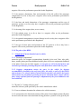
1. Back and seat pans
The back and seat pans are constructed of reinforced plastic and metal; they simulate the
human torso and thigh and are mechanically hinged at the "H" point. A quadrant is
fastened to the probe hinged at the "H" point to measure the actual torso angle. An
adjustable thigh bar, attached to the seat pan, establishes the thigh centreline and serves
as a baseline for the hip angle quadrant.
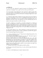
2. Body and leg elements
Lower leg segments are connected to the seat pan assembly at the T-bar joining the knees,
which is a lateral extension of the adjustable thigh bar. Quadrants are incorporated in the
lower leg segments to measure knee angles. Shoe and foot assemblies are calibrated to
measure the foot angle. Two spirit levels orient the device in space. Body element
weights are placed at the corresponding centres of gravity to provide seat penetration
equivalent to a 76 kg male. All joints of the 3-D H machine should be checked for free
movement without encountering noticeable friction.
Page 22
France
Draft proposal
Page 23
ELSA-7-04
France
Draft proposal
Page 24
ELSA-7-04
France
Draft proposal
Page 25
ELSA-7-04
France
Draft proposal
ELSA-7-04
Figure 1 - 3-D H machine elements designation
Figure 2 - Dimensions of the 3-D H machine elements and load distribution
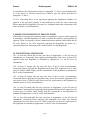
Annex 3 - Appendix 2
THREE-DIMENSIONAL REFERENCE SYSTEM
1. The three-dimensional reference system is defined by three orthogonal planes
established by the vehicle manufacturer (see figure). */
2. The vehicle measuring attitude is established by positioning the vehicle on the
supporting surface such that the co-ordinates of the fiducial marks correspond to the
values indicated by the manufacturer.
3. The co-ordinates of the "R" point and the "H" point are established in relation to the
fiducial marks defined by the vehicle manufacturer.
Page 26
France
Draft proposal
ELSA-7-04
Annex 3 - Appendix 3
REFERENCE DATA CONCERNING SEATING POSITIONS
1. Coding of reference data
Reference data are listed consecutively for each seating position. Seating positions are
identified by a two-digit code. The first digit is an Arabic numeral and designates the row
of seats, counting from the front to the rear of the vehicle. The second digit is a capital
letter which designates the location of the seating position in a row, as viewed in the
direction of forward motion of the vehicle; the following letters shall be used:
Page 27
France
Draft proposal
ELSA-7-04
L = left
C = centre
R = right
R
2. Description of vehicle measuring attitude
2.1. Co-ordinates of fiducial marks
X ..................................................
Y ..................................................
Z ..................................................
3. List of reference data
3.1. Seating position: .....................................................................................
3.1.1. Co-ordinates of "R" point
X ..............................................
Y ..............................................
Z ...............................................
3.1.2. Design
torso
angle: .................................................................................................................................
3.1.3. Specifications for seat adjustment */
horizontal: ..............................
vertical: ..................................
angular: ..................................
torso angle: .............................
Note: List reference data for further seating positions under 3.2., 3.3., etc.
Page 28
France
Draft proposal
ELSA-7-04
Annex 4
COLLISION TEST PROCEDURE
1. INSTALLATIONS
1.1. Testing ground
The test area shall be large enough to accommodate the mobile deformable barrier
propulsion system and to permit after-impact displacement of the vehicle impacted and
installation of the test equipment. The part in which vehicle impact and displacement
occur shall be horizontal, flat and uncontaminated, and representative of a normal, dry,
uncontaminated road surface.
2. TEST CONDITIONS
2.1. The vehicle to be tested shall be stationary.
2.2. The mobile deformable barrier shall have the characteristics set out in annex 5 to this
Regulation. Requirements for the examination are given in the appendix to annex 5. The
mobile deformable barrier shall be equipped with a suitable device to prevent a second
impact on the struck vehicle.
2.3. The trajectory of the mobile deformable barrier longitudinal median vertical plane
shall be perpendicular to the longitudinal median vertical plane of the impacted vehicle.
2.4. The longitudinal vertical median plane of the mobile deformable barrier shall be
coincident within ± 25 mm with a transverse vertical plane passing through the R point of
the front seat adjacent to the struck side of the tested vehicle. The horizontal median
plane limited by the external lateral vertical planes of the front face shall be at the
moment of impact within two planes determined before the test and situated 25 mm
above and below the previously defined plane.
2.5. Instrumentation shall comply with ISO 6487:1987 unless otherwise specified in this
Regulation.
2.6. The stabilised temperature of the test dummy at the time of the side impact test shall
be 22 ± 4°C.
Page 29
France
Draft proposal
ELSA-7-04
3. TEST SPEED
The mobile deformable barrier speed at the moment of impact shall be 50 ± 1 km/h. This
speed shall be stabilised at least 0.5 m before impact. Accuracy of measurement: 1 per
cent. However, if the test was performed at a higher impact speed and the vehicle met the
requirements, the test shall be considered satisfactory.
4. STATE OF THE VEHICLE
4.1. General specification
The test vehicle shall be representative of the series production, shall include all the
equipment normally fitted and shall be in normal running order. Some components may
be omitted or replaced by equivalent masses where this omission or substitution clearly
has no effect on the results of the test.
4.2. Vehicle equipment specification
The test vehicle shall have all the optional arrangements or fittings likely to influence the
results of the test.
4.3. Mass of the vehicle
4.3.1. The vehicle to be tested shall have the reference mass as defined in paragraph 2.10.
of this Regulation. The mass of the vehicle shall be adjusted to ± 1 per cent of the
reference mass.
4.3.2. The fuel tank shall be filled with water to a mass equal to 90 per cent of the mass
of a full load of fuel as specified by the manufacturer.
4.3.3. All the other systems (brake, cooling, etc.) may be empty; in this case, the mass of
the liquids shall be offset.
4.3.4. If the mass of the measuring apparatus on board of the vehicle exceeds the 25 kg
allowed, it may be offset by reductions which have no noticeable effect on the results of
the test.
4.3.5. The mass of the measuring apparatus shall not change each axle reference load by
more than 5 per cent, each variation not exceeding 20 kg.
4.4.
Electric vehicle adjustments
4.4.1.
The high voltage system shall be energized.
4.4.2.
The RESS is at the level specified in the following paragraph (a), (b), or
(c), as appropriate:
(a) At the maximum state of charge recommended by the manufacturer,
as stated in the vehicle operator's manual or on a label that is
permanently affixed to the vehicle;
Page 30
France
Draft proposal
ELSA-7-04
(b) If the manufacturer has made no recommendation, at a state of
charge of not less than 95 percent of the maximum capacity of the
RESS; or
(c) If the RESS are rechargeable only by an energy source on the
vehicle, at any state of charge within the normal operating voltage, as
defined by the vehicle manufacturer.
1.4.4.3.
Energy conversion system: Proposal from OICA together with JASIC
5. PREPARATION OF THE VEHICLE
5.1. The side windows at least on the struck side shall be closed.
5.2. The doors shall be closed, but not locked.
5.3. The transmission shall be placed in neutral and the parking brake disengaged.
5.4. The comfort adjustments of the seats, if any, shall be adjusted to the position
specified by the vehicle manufacturer.
5.5. The seat containing the dummy, and its elements, if adjustable, shall be adjusted as
follows:
5.5.1. The longitudinal adjustment device shall be placed with the locking device
engaged in the position that is nearest to midway between the foremost and rearmost
positions; if this position is between two notches, the rearmost notch shall be used.
5.5.2. The head restraint shall be adjusted such that its top surface is level with the centre
of gravity of the dummy's head; if this is not possible, the head restraint shall be in the
uppermost position.
5.5.3. Unless otherwise specified by the manufacturer, the seat-back shall be set such that
the torso reference line of the three-dimensional H point machine is set at an angle of 25
± 1° towards the rear.
5.5.4. All other seat adjustments shall be at the mid-point of available travel; however,
height adjustment shall be at the position corresponding to the fixed seat, if the vehicle
type is available with adjustable and fixed seats. If locking positions are not available at
the respective mid-points of travel, the positions immediately rearward, down, or
outboard of the mid-points shall be used. For rotational adjustments (tilt), rearward will
be the adjustment direction which moves the head of the dummy rearwards. If the
dummy protrudes outside the normal passenger volume, e.g. head into roof lining, then 1
cm clearance will be provided using: secondary adjustments, seat-back angle, or fore-aft
adjustment in that order.
Page 31
France
Draft proposal
ELSA-7-04
5.6. Unless otherwise specified by the manufacturer, the other front seats shall, if possible,
be adjusted to the same position as the seat containing the dummy.
5.7. If the steering wheel is adjustable, all adjustments are positioned to their mid-travel
locations.
5.8. Tyres shall be inflated to the pressure specified by the vehicle manufacturer.
5.9. The test vehicle shall be set horizontal about its roll axis and maintained by supports
in that position until the side impact dummy is in place and after all preparatory work is
complete.
5.10. The vehicle shall be at its normal attitude corresponding to the conditions set out in
paragraph 4.3. above. Vehicles with suspension enabling their ground clearance to be
adjusted shall be tested under the normal conditions of use at 50 km/h as defined by the
vehicle manufacturer. This shall be assured by means of additional supports, if necessary,
but such supports shall have no influence on the crash behaviour of the test vehicle
during the impact.
6. SIDE IMPACT DUMMY AND ITS INSTALLATION
6.1. The side impact dummy shall comply with the specifications given in annex 6 and be
installed in the front seat on the impact side according to the procedure given in annex 7
to this Regulation.
6.2. The safety-belts or other restraint systems, which are specified for the vehicle, shall
be used. Belts should be of an approved type, conforming to Regulation No. 16 or to
other equivalent requirements and mounted on anchorages conforming to Regulation No.
14 or to other equivalent requirements.
6.3. The safety-belt or restraint system shall be adjusted to fit the dummy in accordance
with the manufacturer's instructions; if there are no manufacturer's instructions, the height
adjustment shall be set at middle position; if this position is not available, the position
immediately below shall be used.
7. MEASUREMENTS TO BE MADE ON THE SIDE IMPACT DUMMY
7.1. The readings of the following measuring devices are to be recorded.
7.1.1. Measurements in the head of the dummy
The resultant triaxial acceleration referring to the head centre of gravity. The head
channel instrumentation shall comply with ISO 6487:1987 with:
CFC: 1000 Hz, and
Page 32
France
Draft proposal
ELSA-7-04
CAC: 150 g
7.1.2. Measurements in the thorax of the dummy
The three thorax rib deflection channels shall comply with ISO 6487:1987
CFC: 1000 Hz
CAC: 60 mm
7.1.3. Measurements in the pelvis of the dummy
The pelvis force channel shall comply with ISO 6487:1987
CFC: 1000 Hz
CAC: 15 kN
7.1.4. Measurements in the abdomen of the dummy
The abdomen force channels shall comply with ISO 6487:1987
CFC: 1000 Hz
CAC: 5 kN
Annex 4 - Appendix 1
DETERMINATION OF PERFORMANCE DATA
The required results of the tests are specified in paragraph 5.2. of this Regulation.
1. HEAD PERFORMANCE CRITERION (HPC)
When head contact takes place, this performance criterion is calculated for the total
duration between the initial contact and the last instant of the final contact.
HPC is the maximum value of the expression:
Page 33
France
Draft proposal
ELSA-7-04
where a is the resultant acceleration at the centre of gravity of the head in metres per
second divided by 9.81 recorded versus time and filtered at channel frequency class 1000
Hz; t1 and t2 are any two times between the initial contact and the last instant of the final
contact.
2. THORAX PERFORMANCE CRITERIA
2.1. Chest deflection: the peak chest deflection is the maximum value of deflection on
any rib as determined by the thorax displacement transducers, filtered at channel
frequency class 180 Hz.
2.2. Viscous criterion: the peak viscous response is the maximum value of VC on any rib
which is calculated from the instantaneous product of the relative thorax compression
related to the half thorax and the velocity of compression derived by differentiation of the
compression, filtered at channel frequency class 180 Hz. For the purposes of this
calculation the standard width of the half thorax rib cage is 140 mm.
VC = max [(D/0.14) • (dD/dt)]
where D (metres) = rib deflection
The calculation algorithm to be used is set out in annex 4, appendix 2.
3. ABDOMEN PROTECTION CRITERION
The peak abdominal force is the maximum value of the sum of the three forces measured
by transducers mounted 39 mm below the surface on the crash side, CFC 600 Hz.
4. PELVIS PERFORMANCE CRITERION
The pubic symphysis peak force (PSPF) is the maximum force measured by a load cell at
the pubic symphysis of the pelvis, filtered at channel frequency class 600 Hz.
Annex 4 - Appendix 2
THE PROCEDURE FOR CALCULATING THE VISCOUS
CRITERION FOR EUROSID 1
The Viscous Criterion, VC, is calculated as the instantaneous product of the compression
and the rate of deflection of the rib. Both are derived from the measurement of rib
deflection. The rib deflection response is filtered once at Channel Frequency Class 180.
The compression at time (t) is calculated as the deflection from this filtered signal
expressed as the proportion of the half width of the EUROSID 1 chest, measured at the
metal ribs (0.14 metres):
Page 34
France
C
(t)
Draft proposal
ELSA-7-04
= D /0.14
(t)
The rib deflection velocity at time (t) is calculated from the filtered deflection as:
V
(t)
= (8 [D
(t+1)
where D
(t)
-D
(t-1)
] - [D
(t+2)
-D
(t-2)
])/(12∂t)
is the deflection at time (t) in metres and ∂t is the time interval in seconds
between the measurements of deflection. The maximum value of ∂t shall be 1,25 x10⁻⁴
seconds.
This calculation procedure is shown diagrammatically below:
Annex 5
MOBILE DEFORMABLE BARRIER
Page 35
France
Draft proposal
ELSA-7-04
CHARACTERISTICS
1. CHARACTERISTICS OF THE MOBILE DEFORMABLE BARRIER
1.1. The mobile deformable barrier (MDB) includes both an impactor and a trolley.
1.2. The total mass shall be 950 ± 20 kg.
1.3. The centre of gravity shall be situated in the longitudinal median vertical plane
within 10 mm, 1,000 ± 30 mm behind the front axle and 500 ± 30 mm above the ground.
1.4. The distance between the front face of the impactor and the centre of gravity of the
barrier shall be 2,000 ± 30 mm.
1.5. The ground clearance of the impactor shall be 300 + 5 mm measured in static
conditions from the lower edge of the lower front plate, before the impact.
1.6. The front and rear track width of the trolley shall be 1,500 ± 10 mm.
1.7. The wheel base of the trolley shall be 3,000 ± 10 mm.
2. CHARACTERISTICS OF THE IMPACTOR
The impactor consists of six single blocks of aluminium honeycomb, which have been
processed in order to give a progressively increasing level of force with increasing
deflection (see paragraph 2.1.). Front and rear aluminium plates are attached to the
aluminium honeycomb blocks.
2.1. Honeycomb blocks
2.1.1. Geometrical characteristics
2.1.1.1. The impactor consists of 6 joined zones whose forms and positioning are shown
in figures 1 and 2. The zones are defined as 500 ± 5 mm x 250 ± 3 mm in figures 1 and 2.
The 500 mm should be in the W direction and the 250 mm in the L direction of the
aluminium honeycomb construction (see figure 3).
2.1.1.2. The impactor is divided into 2 rows. The lower row shall be 250 ± 3 mm high,
and 500 ± 2 mm deep after pre-crush (see paragraph 2.1.2.), and deeper than the upper
row by 60 ± 2 mm.
2.1.1.3. The blocks must be centred on the six zones defined in figure 1 and each block
(including incomplete cells) should cover completely the area defined for each zone).
2.1.2. Pre-crush
Page 36
France
Draft proposal
ELSA-7-04
2.1.2.1. The pre-crush shall be performed on the surface of the honeycomb to which the
front sheets are attached.
2.1.2.2. Blocks 1, 2 and 3 should be crushed by 10 ± 2 mm on the top surface prior to
testing to give a depth of 500 ± 2 mm (figure 2).
2.1.2.3. Blocks 4, 5 and 6 should be crushed by 10 ± 2 mm on the top surface prior to
testing to give a depth of 440 ± 2 mm.
2.1.3. Material characteristics
2.1.3.1. The cell dimensions shall be 19 mm ± 10 per cent for each block (see figure 4).
2.1.3.2. The cells must be made of 3003 aluminium for the upper row.
2.1.3.3. The cells must be made of 5052 aluminium for the lower row.
2.1.3.4. The aluminium honeycomb blocks should be processed such that the force
deflection-curve when statically crushed (according to the procedure defined in paragraph
2.1.4.) is within the corridors defined for each of the six blocks in appendix 1 to this
annex. Moreover, the processed honeycomb material used in the honeycomb blocks to be
used for constructing the barrier, should be cleaned in order to remove any residue that
may have been produced during the processing of the raw honeycomb material.
2.1.3.5. The mass of the blocks in each batch shall not differ by more than 5 per cent of
the mean block mass for that batch.
2.1.4. Static tests
2.1.4.1. A sample taken from each batch of processed honeycomb core shall be tested
according to the static test procedure described in paragraph 5.
2.1.4.2. The force-compression for each block tested shall lie within the force deflection
corridors defined in appendix 1. Static force-deflection corridors are defined for each
block of the barrier.
2.1.5. Dynamic test
2.1.5.1. The dynamic deformation characteristics, when impacted according to the
protocol described in paragraph 6.
2.1.5.2. Deviation from the limits of the force-deflection corridors characterising the
rigidity of the impactor - as defined in appendix 2 - may be allowed provided that:
2.1.5.2.1. the deviation occurs after the beginning of the impact and before the
Page 37
France
Draft proposal
ELSA-7-04
deformation of the impactor is equal to 150 mm;
2.1.5.2.2. the deviation does not exceed 50 per cent of the nearest instantaneous
prescribed limit of the corridor;
2.1.5.2.3. each deflection corresponding to each deviation does not exceed 35 mm of
deflection, and the sum of these deflections does not exceed 70 mm (see appendix 2 to
this annex);
2.1.5.2.4. the sum of energy derived from deviating outside the corridor does not exceed
5 per cent of the gross energy for that block.
2.1.5.3. Blocks 1 and 3 are identical. Their rigidity is such that their force deflection
curves fall between corridors of figure 2a.
2.1.5.4. Blocks 5 and 6 are identical. Their rigidity is such that their force deflection
curves fall between corridors of figure 2d.
2.1.5.5 The rigidity of block 2 is such that its force deflection curves fall between
corridors of figure 2b.
2.1.5.6. The rigidity of block 4 is such that its force deflection curves fall between
corridors of figure 2c.
2.1.5.7. The force-deflection of the impactor as a whole shall fall between corridors of
figure 2e.
2.1.5.8. The force-deflection curves shall be verified by a test detailed in annex 5,
paragraph 6., consisting of an impact of the barrier against a dynamometric wall at 35 ±
0.5 km/h.
2.1.5.9. The dissipated energy 1/ against blocks 1 and 3 during the test shall be equal to
9.5 ± 2 kJ for these blocks.
2.1.5.10. The dissipated energy against blocks 5 and 6 during the test shall be equal to 3.5
± 1 kJ for these blocks.
2.1.5.11. The dissipated energy against block 4 shall be equal to 4 ± 1 kJ.
2.1.5.12. The dissipated energy against block 2 shall be equal to 15 ± 2 kJ.
2.1.5.13. The dissipated total energy during the impact shall be equal to 45 ± 3 kJ.
2.1.5.14. The maximum impactor deformation from the point of first contact, calculated
from integration of the accelerometers according to paragraph 6.6.3., shall be equal to
330 ± 20 mm.
Page 38
France
Draft proposal
ELSA-7-04
2.1.5.15. The final residual static impactor deformation measured after the dynamic test
at level B (figure 2) shall be equal to 310 ± 20 mm.
2.2. Front plates
2.2.1. Geometrical characteristics
2.2.1.1. The front plates are 1,500 ± 1 mm wide and 250 ± 1 mm high. The thickness is
0.5 ± 0.06 mm.
2.2.1.2. When assembled the overall dimensions of the impactor (defined in figure 2)
shall be: 1,500 ± 2.5 mm wide and 500 ± 2.5 mm high.
2.2.1.3. The upper edge of the lower front plate and the lower edge of the upper front
plate should be aligned within 4 mm.
2.2.2. Material characteristics
2.2.2.1. The front plates are manufactured from aluminium of series AlMg2 to AlMg3
with elongation ≥ 12 per cent, and a UTS ≥ 175 N/mm2.
The material of the impactor must be an aluminium honeycomb. Other materials can be
used if equal results as described in paragraph 2.3. have been proved to the satisfaction of
the Technical Service. In any case the type of impactor must be indicated in the test
report.
2.3. Back plate
2.3.1. Geometric characteristics
2.3.1.1.The geometric characteristics shall be according to figures 5 and 6.
2.3.2. Material characteristics
2.3.2.1.The back plate shall consist of a 3 mm aluminium sheet. The back plate shall be
manufactured from aluminium of series AlMg2 to AlMg3 with a hardness between 50
and 65 HBS. This plate shall be perforated with holes for ventilation: the location, the
diameter and pitch are shown in figures 5 and 7.
2.4. Location of the honeycomb blocks
2.4.1. The honeycomb blocks shall be centred on the perforated zone of the back plate
(figure 5).
2.5. Bonding
Page 39
France
Draft proposal
ELSA-7-04
2.5.1. For both the front and the back plates, a maximum of 0.5 kg/m2 shall be applied
evenly directly over the surface of the front plate, giving a maximum film thickness of
0.5 mm. The adhesive to be used throughout should be a two-part polyurethane {such as
Ciba Geigy XB5090/1 resin with XB5304 hardener} or equivalent.
2.5.2. For the back plate the minimum bonding strength shall be 0.6 MPa, (87 psi), tested
according to paragraph 2.4.3.
2.5.3. Bonding strength tests:
2.5.3.1. Flatwise tensile testing is used to measure bond strength of adhesives according
to ASTM C297-61.
2.5.3.2. The test piece should be 100 mm x 100 mm, and 15 mm deep, bonded to a
sample of the ventilated back plate material. The honeycomb used should be
representative of that in the impactor, i.e. chemically etched to an equivalent degree as
that near to the back plate in the barrier but without pre-crushing.
2.6. Traceability
2.6.1. Impactors shall carry consecutive serial numbers which are stamped, etched or
otherwise permanently attached, from which the batches for the individual blocks and the
date of manufacture can be established
2.7. Impactor attachment
2.7.1. The fitting on the trolley must be according to figure 8. The fitting will use six M8
bolts, and nothing shall be larger than the dimensions of the barrier in front of the wheels
of the trolley. Appropriate spacers must be used between the lower back plate flange and
the trolley face to avoid bowing of the back plate when the attachment bolts are
tightened.
3. VENTILATION SYSTEM
3.1. The interface between the trolley and the ventilation system should be solid, rigid
and flat.
The ventilation device is part of the trolley and not of the impactor as supplied by the
manufacturer. Geometrical characteristics of the ventilation device shall be according to
figure 9.
3.2. Ventilation device mounting procedure.
3.2.1. Mount the ventilation device to the front plate of the trolley;
3.2.2. Ensure that a 0.5 mm thick gauge cannot be inserted between the ventilation device
and the trolley face at any point. If there is a gap greater than 0.5 mm, the ventilation
frame will need to be replaced or adjusted to fit without a gap of > 0.5 mm.
Page 40
France
Draft proposal
ELSA-7-04
3.2.3. Dismount the ventilation device from the front of the trolley;
3.2.4. Fix a 1.0 mm thick layer of cork to the front face of the trolley;
3.2.5. Re-mount the ventilation device to the front of the trolley and tighten to exclude air
gaps.
4. CONFORMITY OF PRODUCTION
The conformity of production procedures shall comply with those set out in the
Agreement, Appendix 2 (E/ECE/324-E/ECE/TRANS/505/Rev.2), with the following
requirements:
4.1. The manufacturer shall be responsible for the conformity of production procedures
and for that purpose must in particular:
4.1.1. Ensure the existence of effective procedures so that the quality of the products can
be inspected,
4.1.2. Have access to the testing equipment needed to inspect the conformity of each
product,
4.1.3. Ensure that the test results are recorded and that the documents remain available
for a time period of 10 years after the tests,
4.1.4. Demonstrate that the samples tested are a reliable measure of the performance of
the batch (examples of sampling methods according to batch production are given
below).
4.1.5. Analyse results of tests in order to verify and ensure the stability of the barrier
characteristics, making allowance for variations of an industrial production, such as
temperature, raw materials quality, time of immersion in chemical, chemical
concentration, neutralisation etc, and the control of the processed material in order to
remove any residue from the processing,
4.1.6. Ensure that any set of samples or test pieces giving evidence of non-conformity
gives rise to a further sampling and test. All the necessary steps must be taken to restore
conformity of the corresponding production.
4.2. The manufacturer's level of certification must be at least ISO 9002 standard.
4.3. Minimum conditions for the control of production: the holder of an agreement will
ensure the control of conformity following the methods hereunder described.
4.4. Examples of sampling according to batch
4.4.1. If several examples of one block type are constructed from one original block of
aluminium honeycomb and are all treated in the same treatment bath (parallel production),
one of these examples could be chosen as the sample, provided care is taken to ensure
Page 41
France
Draft proposal
ELSA-7-04
that the treatment is evenly applied to all blocks. If not, it may be necessary to select
more than one sample.
4.4.2. If a limited number of similar blocks (say three to twenty) are treated in the same
bath (serial production), then the first and last block treated in a batch, all of which are
constructed from the same original block of aluminium honeycomb, should be taken as
representative samples. If the first sample complies with the requirements but the last
does not, it may be necessary to take further samples from earlier in the production until a
sample that does comply is found. Only the blocks between these samples should be
considered to be approved.
4.4.3. Once experience is gained with the consistency of production control, it may be
possible to combine both sampling approaches, so that more than one groups of parallel
production can be considered to be a batch provided samples from the first and last
production groups comply.
5. STATIC TESTS
5.1. One or more samples (according to the batch method) taken from each batch of
processed honeycomb core shall be tested, according to the following test procedure:
5.2. The sample size of the aluminium honeycomb for static tests shall be the size of a
normal block of the impactor, that is to say 250 mm x 500 mm x 440 mm for top row and
250 mm x 500 mm x 500 mm for the bottom row.
5.3. The samples should be compressed between two parallel loading plates which are at
least 20 mm larger that the block cross section.
5.4. The compression speed shall be 100 millimetres per minute, with a tolerance of 5 per
cent.
5.5. The data acquisition for static compression shall be sampled at a minimum of 5 Hz.
5.6. The static test shall be continued until the block compression is at least 300 mm for
blocks 4 to 6 and 350 mm for blocks 1 to 3.
6. DYNAMIC TESTS
For every 100 barrier faces produced, the manufacturer shall make one dynamic test
against a dynamometric wall supported by a fixed rigid barrier, according to the method
described below.
6.1. Installation
6.1.1. Testing ground
Page 42
France
Draft proposal
ELSA-7-04
6.1.1.1. The test area shall be large enough to accommodate the run-up-track of the
mobile deformable barrier, the rigid barrier and the technical equipment necessary for the
test. The last part of the track, for at least 5 metres before the rigid barrier, shall be
horizontal, flat and smooth.
6.1.2. Fixed rigid barrier and dynamometric wall
6.1.2.1. The rigid wall shall consist of a block of reinforced concrete not less than 3
metres wide and not less than 1.5 metres high. The thickness of the rigid wall shall be
such that it weighs at least 70 tonnes.
6.1.2.2. The front face shall be vertical, perpendicular to the axis of the run-up-tack and
equipped with six load cell plates, each capable of measuring the total load on the
appropriate block of the mobile deformable barrier impactor at the moment of impact.
The load cell impact plate area centres shall align with those of the six impact zones of
the mobile deformable barrier face. Their edges shall clear adjacent areas by 20 mm such
that, within the tolerance of impact alignment of the MDB, the impact zones will not
contact the adjacent impact plate areas. Cell mounting and plate surfaces shall be in
accordance with the requirements set out in the annex to standard ISO 6487:1987.
6.1.2.3. Surface protection, comprising a plywood face (thickness: 12 ± 1 mm), is added
to each load cell plate such that it shall not degrade the transducer responses.
6.1.2.4. The rigid wall shall be either anchored in the ground or placed on the ground
with, if necessary, additional arresting devices to limit its deflection. A rigid wall (to
which the load cells are attached) having different characteristics but giving results that
are at least equally conclusive may be used.
6.2. Propulsion of the mobile deformable barrier
At the moment of impact the mobile deformable barrier shall no longer be subject to the
action of any additional steering or propelling device. It shall reach the obstacle on a
course perpendicular to the front surface of the dynamometric wall. Impact alignment
shall be accurate to within 10 mm.
6.3. Measuring instruments
6.3.1. Speed
The impact speed shall be 35 ± 0.5 km/h the instrument used to record the speed on
impact shall be accurate to within 0.1 percent.
6.3.2. Loads
Measuring instruments shall meet the specifications set forth in ISO 6487:1987
CFC for all blocks: 60 Hz
Page 43
France
Draft proposal
ELSA-7-04
CAC for blocks 1 and 3: 200 kN
CAC for blocks 4,5 and 6: 100 kN
CAC for block 2: 200 kN
6.3.3. Acceleration
6.3.3.1. The acceleration in the longitudinal direction shall be measured at three separate
positions on the trolley, one centrally and one at each side, at places not subject to
bending.
6.3.3.2. The central accelerometer shall be located within 500 mm of the location of the
centre of gravity of the MDB and shall lie in a vertical longitudinal plane which is within
± 10 mm of the centre of gravity of the MDB.
6.3.3.3. The side accelerometers shall be at the same height as each other ± 10 mm and at
the same distance from the front surface of the MDB ± 20 mm
6.3.3.4. The instrumentation shall comply with ISO 6487:1987 with the following
specifications:
CFC 1,000 Hz (before integration)
CAC 50 g
6.4. General specifications of barrier
6.4.1. The individual characteristics of each barrier shall comply with paragraph 1. of this
annex and shall be recorded.
6.5. General specifications of the impactor
6.5.1. The suitability of an impactor as regards the dynamic test requirements shall be
confirmed when the outputs from the six load cell plates each produce signals complying
with the requirements indicated in this annex.
6.5.2. Impactors shall carry consecutive serial numbers which are stamped, etched or
otherwise permanently attached, from which the batches for the individual blocks and the
date of manufacture can be established.
6.6. Data processing procedure
6.6.1. Raw data: At time T = T0, all offsets should be removed from the data. The method
by which offsets are removed shall be recorded in the test report.
6.6.2. Filtering
Page 44
France
Draft proposal
ELSA-7-04
6.6.2.1. The raw data will be filtered prior to processing/calculations.
6.6.2.2. Accelerometer data for integration will be filtered to CFC 180, ISO 6487:1987.
6.6.2.3. Accelerometer data for impulse calculations will be filtered to CFC 60, ISO
6487:1987.
6.6.2.4. Load cell data will be filtered to CFC 60, ISO 6487:1987.
6.6.3. Calculation of MDB face deflection
6.6.3.1. Accelerometer data from all three accelerometers individually (after filtering at
CFC 180), will be integrated twice to obtain deflection of the barrier deformable element.
6.6.3.2. The initial conditions for deflection are:
6.6.3.2.1. velocity = impact velocity (from speed measuring device).
6.6.3.2.2. deflection = 0
6.6.3.3. The deflection at the left hand side, mid-line and right hand side of the mobile
deformable barrier will be plotted with respect to time.
6.6.3.4. The maximum deflection calculated from each of the three accelerometers should
be within 10 mm. If it is not the case, then the outlier should be removed and difference
between the deflection calculated from the remaining two accelerometers checked to
ensure that it is within 10 mm.
6.6.3.5. If the deflections as measured by the left hand side, right hand side and mid-line
accelerometers are within 10 mm, then the mean acceleration of the three accelerometers
should be used to calculate the deflection of the barrier face.
6.6.3.6. If the deflection from only two accelerometers meets the 10 mm requirement,
then the mean acceleration from these two accelerometers should be used to calculate the
deflection for the barrier face.
6.6.3.7. If the deflections calculated from all three accelerometers (left hand side, right
hand side and mid-line) are NOT within the 10 mm requirement, then the raw data should
be reviewed to determine the causes of such large variation. In this case the individual
test house will determine which accelerometer data should be used to determine mobile
deformable barrier deflection or whether none of the accelerometer readings can be used,
in which case, the certification test must be repeated. A full explanation should be given
in the test report.
6.6.3.8. The mean deflection-time data will be combined with the load cell wall
force-time data to generate the force-deflection result for each block.
Page 45
France
Draft proposal
ELSA-7-04
6.6.4. Calculation of energy
The absorbed energy for each block and for the whole MDB face should be calculated up
to the point of peak deflection of the barrier.
where:
t0 is the time of first contact
t1 is the time where the trolley comes to rest, i.e. where u = 0.
s is the deflection of the trolley deformable element calculated according to paragraph
6.6.3.
6.6.5. Verification of dynamic force data
6.6.5.1. Compare the total impulse, I, calculated from the integration of the total force
over the period of contact, with the momentum change over that period (M*? V).
6.6.5.2. Compare the total energy change to the change in kinetic energy of the MDB,
given by:
where Vi is the impact velocity and M the whole mass of the MDB
If the momentum change (M*? V) is not equal to the total impulse (I) ± 5 per cent, or if
the total energy absorbed (? E ) is not equal to the kinetic energy, E ± 5 per cent, then
n
K
the test data must be examined to determine the cause of this error.
DESIGN OF IMPACTOR 2/
Page 46
France
Draft proposal
Figure 1
Figure 2
Page 47
ELSA-7-04
France
Draft proposal
Figure 3 - Aluminium Honeycomb Orientation
Figure 4 - Dimension of Aluminium Honeycomb Cells
DESIGN OF THE BACK PLATE
Page 48
ELSA-7-04
France
Draft proposal
Figure 5
Front View
Page 49
ELSA-7-04
France
Draft proposal
Figure 6
Attachment of backplate to ventillation device and trolley face plate
Page 50
ELSA-7-04
France
Draft proposal
ELSA-7-04
Figure 7 - Staggered pitch for the back plate ventilation holes
Top and bottom back plate flanges
Note: The attachment holes in the bottom flange may be opened to slots, as shown
below, for ease of attachment provided sufficient grip can be developed to avoid
detachment during the whole impact test.
Page 51
France
Draft proposal
ELSA-7-04
VENTILATION FRAME
The ventilation device is a structure made of a plate that is 5 mm thick and 20 mm wide.
Only the vertical plates are perforated with nine 8 mm holes in order to let air circulate
horizontally.
Page 52
France
Draft proposal
Figure 9
Page 53
ELSA-7-04
France
Draft proposal
ELSA-7-04
Annex 5 - Appendix 1
FORCE-DEFLECTION CURVES FOR STATIC TESTS
Blocks 1 & 3 - Figure 1a
Page 54
France
Draft proposal
Block 2 - Figure 1b
Page 55
ELSA-7-04
France
Draft proposal
Block 4 - Figure 1c
Page 56
ELSA-7-04
France
Draft proposal
ELSA-7-04
Blocks 5 & 6 - Figure 1d
Annex 5 - Appendix 2
FORCE-DEFLECTION CURVES FOR DYNAMIC TESTS
Page 57
France
Draft proposal
Page 58
ELSA-7-04
France
Draft proposal
Page 59
ELSA-7-04
France
Draft proposal
Page 60
ELSA-7-04
France
Draft proposal
ELSA-7-04
Annex 6
TECHNICAL DESCRIPTION OF THE SIDE
IMPACT DUMMY
1. GENERAL
1.1. The side impact dummy prescribed in this Regulation, including the instrumentation
and calibration, is described in technical drawings and a user's manual 1/.
1.2. The dimensions and masses of the side impact dummy represent a 50th percentile
adult male, without lower arms.
1.3. The side impact dummy consists of a metal and plastic skeleton covered by
flesh-simulating rubber, plastic and foam.
2. CONSTRUCTION
2.1. For an overview of the side impact dummy see Figure 1 for a scheme and the parts
breakdown in Table 1 of this annex
2.2. Head
2.2.1. The head is shown as part No. 1 in figure 1 of this annex.
2.2.2. The head consists of an aluminium shell covered by a pliable vinyl skin. The
interior of the shell is a cavity accommodating triaxial accelerometers and ballast.
2.2.3. At the head-neck interface a load cell replacement is built in. This part can be
replaced with an upper neck load-cell.
2.3. Neck
2.3.1. The neck is shown as part No. 2 in figure 1 of this annex.
2.3.2. The neck consists of a head-neck interface piece, a neck-thorax interface piece and
a central section that links the two interfaces to one another.
2.3.3. The head-neck interface piece (part No. 2a) and the neck-thorax interface piece
(part No. 2c) both consist of two aluminium disks linked together by means of a half
spherical screw and eight rubber buffers.
2.3.4. The cylindrical central section (part No. 2b) is made of rubber. At both sides an
aluminium disk of the interface pieces is moulded in the rubber part.
Page 61
France
Draft proposal
ELSA-7-04
2.3.5. The neck is mounted on the neck-bracket, shown as part No. 2d in Figure 1 of this
annex. This bracket can optionally be replaced with a lower neck load-cell.
2.3.6. The angle between the two faces of the neck-bracket is 25 degrees. Because the
shoulder block is inclined 5 degrees backwards, the resulting angle between the neck and
torso is 20 degrees.
2.4. Shoulder
2.4.1. The shoulder is shown as part No. 3 in figure 1 of this annex.
2.4.2. The shoulder consists of a shoulder block, two clavicles and a shoulder cap.
2.4.3. The shoulder box (part No. 3a) consists of an aluminium spacer block, an
aluminium plate on top and an aluminium plate on the bottom of the spacer block. Both
plates are covered with a polytetrafluoretheen (PTFE)-coating.
2.4.4. The clavicles (part No. 3b), made of cast polyurethane (PU)-resin, are designed to
evolve over the spacer block. The clavicles are held back in their neutral position by two
elastic cords (part No. 3c) which are clamped to the rear of the shoulder box. The outer
edge of both clavicles accommodates a design allowing for standard arm positions.
2.4.5. The shoulder cap (part No. 3d) is made of low-density polyurethane foam and is
attached to the shoulder block.
2.5. Thorax
2.5.1. The thorax is shown as part No. 4 in figure 1 of this annex.
2.5.2. The thorax consists of a rigid thoracic spine box and three identical rib modules.
2.5.3. The thoracic spine box (part No. 4a) is made of steel. On the rear surface a steel
spacer and curved, polyurethane (PU)-resin, back plate is mounted (part No. 4b).
2.5.4. The top surface of the thoracic spine box is inclined 5 degrees backwards.
2.5.5. At the lower side of the spine box a T12 load cell or load cell replacement (part
No. 4j) is mounted.
2.5.6. A rib module (part No. 4c) consists of a steel rib bow covered by a flesh-simulating
open-cell polyurethane (PU) foam (part No. 4d), a linear guide system assembly (part No.
4e) linking the rib and spine box together, a hydraulic damper (part No. 4f) and a stiff
damper spring (part No. 4g).
2.5.7. The linear guide system (part No. 4e) allows the sensitive rib side of the rib bow
(part No. 4d) to deflect with respect to the spine box (part No. 4a) and the non-sensitive
side. The guide system assembly is equipped with linear needle bearings.
Page 62
France
Draft proposal
ELSA-7-04
2.5.8. A tuning spring is located in the guide system assembly (part No. 4h).
2.5.9. A rib displacement transducer (part No. 4i) can be installed on the spine box
mounted part of guide system (part No. 4e) and connected to the outer end of the guide
system at the sensitive side of the rib.
2.6. Arms
2.6.1. The arms are shown as part No. 5 in figure 1 of this annex.
2.6.2. The arms have a plastic skeleton covered by a polyurethane (PU) flesh
representation with a polyvinylchloride (PVC) skin. The flesh representation consists of a
high-density polyurethane (PU) moulding upper part and a polyurethane (PU) foam lower
part.
2.6.3. The shoulder-arm joint allows for discrete arm positions at 0, 40 and 90 degree
setting with respect to the torso axis.
2.6.4. The shoulder/arm joint allows for a flexion/extension rotation only.
2.7. Lumbar spine
2.7.1. The lumbar spine is shown as part No. 6 in figure 1 of this annex.
2.7.2. The lumbar spine consists of a solid rubber cylinder with two steel interface plates
at each end, and a steel cable inside the cylinder.
2.8. Abdomen
2.8.1. The abdomen is shown as part No. 7 in figure 1 of this annex.
2.8.2. The abdomen consists of a metal casting and a polyurethane foam covering.
2.8.3. The central part of the abdomen is a metal casting (part No. 7A). A cover plate is
mounted on top of the casting.
2.8.4. The covering (part No. 7b) is made of polyurethane(PU) foam. A curved slab of
rubber filled with lead-pellets is integrated in the foam covering at both sides.
2.8.5. Between the foam covering and the rigid casting at each side of the abdomen,
either three force transducers (part No. 7c) or three non-measuring replacement units can
be mounted.
2.9. Pelvis
2.9.1. The pelvis is shown as part No. 8 in figure 1 of this annex.
2.9.2. The pelvis consists of a sacrum block, two iliac wings, two hip joints assemblies
and a flesh simulating foam covering.
Page 63
France
Draft proposal
ELSA-7-04
2.9.3. The sacrum (part No. 8a) consists of a mass tuned metal block and a metal plate
mounted on top of this block. In the aft side of the block is a cavity to facilitate the
application of instrumentation.
2.9.4. The iliac wings (part No. 8b) are made of polyurethane(PU)-resin.
2.9.5. The hip joints assemblies (part No. 8c) are made of steel parts. They consist of an
upper femur bracket and a ball joint connected to an axle passing through the dummy's
H-point.
The upper femur bracket abduction and adduction capability is buffered by rubber stops
at the ends of the range of motion.
2.9.6. The flesh system (part No. 8d) is made of a polyvinlychloride (PVC) skin filled
with polyurethane (PU) foam. At the H-point location the skin is replaced by open-cell
polyurethane (PU) foam block (part No. 8e) backed up with a steel plate fixed on the iliac
wing by an axle support going through the ball joint.
2.9.7. The iliac wings are attached to the sacrum block at the aft side and linked together
at the pubic symphysis location by a force transducer (part No. 8f) or a replacement
transducer.
2.10. Legs
2.10.1. The legs are shown as part No. 9 in figure 1 of this annex.
2.10.2. The legs consist of a metal skeleton covered by flesh-stimulating polyurethane
(PU) foam with a polyvinlychloride (PVC) skin.
2.10.3. A high-density polyurethane (PU) moulding with a polyvinlychloride (PVC) skin
represents the thigh flesh of the upper legs.
2.10.4. The knee and ankle joint allow for a flexion/extension rotation only.
2.11. Suit
2.11.1. The suit is not shown in figure 1 of this annex.
2.11.2. The suit is made of rubber and covers the shoulders, thorax, upper part of the
arms, the abdomen and lumbar spine, the upper part of the pelvis.
Figure 1.
CONSTRUCTION OF SIDE IMPACT DUMMY
Page 64
France
Draft proposal
Page 65
ELSA-7-04
France
Draft proposal
ELSA-7-04
Table 1 - Side Impact Dummy Components (see Figure 1)
Part
1
2
No.
2a
2b
2c
2d
3
3a
3b
3c
3d
4
4a
4b
4c
4d
4e
4f
4g
4h
4i
4j
5
6
7
7a
7b
7c
8
8a
8b
8c
8d
8e
8f
9
10
Description
Head
Neck
Head-neck interface
Central section
Neck-thorax interface
Neck-bracket
Shoulder
Shoulder box
Clavicle
Elastic cord
Shoulder foam cap
Thorax
Thoracic spine
Back plate (curved)
Rib module
Rib bow covered with flesh
Piston-cylinder assembly
Damper
Stiff damper spring
Tuning spring
Displacement transducer
T12 load cell or load cell replacement
Arm
Lumbar spine
Abdomen
Central casting
Foam covering
Force transducer or replacement
Pelvis
Sacrum block
Iliac wings
Hip joint assembly
Flesh covering
H-point foam block
Force transducer or replacement
Leg
Suit
Page 66
Numberper dummy
1
1
1
1
1
1
1
1
2
2
1
1
1
1
3
3
3
3
3
3
3
1
2
1
1
1
1
3
1
1
2
2
1
1
1
2
1
France
Draft proposal
ELSA-7-04
3. ASSEMBLY OF THE DUMMY
3.1. Head-neck
3.1.1. The required torque on the half spherical screws for assembly of the neck is 10
Nm.
3.1.2. The head -upper neck load cell assembly is mounted to the head-neck interface
plate of the neck by four screws.
3.1.3. The neck-thorax interface plate of the neck is mounted to the neck-bracket by four
screws.
3.2. Neck-shoulder-thorax
3.2.1. The neck-bracket is mounted to the shoulder block by four screws.
3.2.2. The shoulder-block is mounted to the top-surface of the thoracic spine box by three
screws.
3.3. Shoulder-arm
3.3.1. The arms are mounted to the shoulder clavicles by means of a screw and an axial
bearing. The screw shall be tightened to obtain a 1 - 2 g holding force of the arm on its
pivot.
3.4. Thorax-lumbar spine-abdomen
3.4.1. The mounting direction of rib modules in the thorax shall be adapted to the
required impact side.
3.4.2. A lumbar spine adapter is mounted to the T12 load cell or load cell replacement at
the lower part of the thoracic spine by two screws.
3.4.3. The lumbar spine adapter is mounted to the top plate of the lumbar spine with four
screws.
3.4.4. The mounting flange of the central abdominal casting is clamped between the
lumbar spine adapter and the lumbar spine top plate.
3.4.5. The location of the abdominal force transducers shall be adapted to the required
impact side.
3.5. Lumbar spine-pelvis-legs
3.5.1. The lumbar spine is mounted to the lumbar spine bottom plate by three screws. In
case of using the lower lumbar spine load cell four screws are used.
3.5.2. The lumbar spine bottom plate is mounted to the sacrum block of the pelvis by
Page 67
France
Draft proposal
ELSA-7-04
three screws.
3.5.3. The legs are mounted to the upper femur bracket of the pelvis hip joint assembly
by a screw.
3.5.4. T The knee and ankle links in the legs can be adjusted to obtain a 1 - 2 g holding
force.
4. MAIN CHARACTERISTICS
4.1. Mass
4.1.1. The masses of the main dummy components are presented in table 2 of this annex.
Table 2 - Dummy Component Masses
Component
(body part)
Head
Mass (kg) Tolerance
±(kg)
4.0
0.2
Neck
Thorax
1.0
22.4
0.05
1.0
Arm (each)
Abdomen and
lumbar spine
Pelvis
1.3
5.0
0.1
0.25
12.0
0.6
Leg (each)
12.7
0.6
Total dummy
72.0
1.2
Principle contents
Complete head assembly including tri-axial
accelerometer and upper neck load cell or
replacement
Neck, not including neck bracket
Neck bracket, shoulder cap, shoulders assembly,
arm attachment bolts, spine box, torso back plate,
rib modules, rib deflection transducers, torso back
plate load cell or replacement, T12-load cell or
replacement, abdomen central casting, abdominal
force transducers, 2/3 of suit
Upper arm, including arm positioning plate (each)
Abdomen flesh covering and lumbar spine
Sacrum block, lumbar spine mounting plate, hip
ball joints, upper femur brackets, iliac wings, pubic
force transducer, pelvis flesh covering, 1/3 of suit
Foot, lower and upper leg and flesh as far as
junction with upper femur (each)
4.2. Principal dimensions
4.2.1. The principal dimensions of the side impact dummy, based on figure 2 of this
annex, are given in table 3 of this annex.
The dimensions are measured without suit
Page 68
France
Draft proposal
Figure 2 - Measurements for principal dummy dimensions
(see table 3)
Page 69
ELSA-7-04
France
Draft proposal
Page 70
ELSA-7-04
France
Draft proposal
ELSA-7-04
Table 3 - Principal Dummy Dimensions
No.
1
2
3
4
5
6
7
8
9
10
11
12
13
14
15
16
Parameter
Sitting height
Seat to shoulder joint
Seat to lower face of thoracic spine box
Seat to hip joint (centre of bolt)
Sole to seat, sitting
Head width
Shoulder / arm width
Thorax width
Abdomen width
Pelvis lap width
Head depth
Thorax depth
Abdomen depth
Pelvis depth
Back of buttocks to hip joint (centre of bolt)
Back of buttocks to front knee
Dimension (mm)
909 ± 9
565 ± 7
351 ± 5
100 ± 3
442 ± 9
155 ± 3
470 ± 9
327 ± 5
280 ± 7
366 ± 7
201 ± 5
267 ± 5
199 ± 5
240 ± 5
155 ± 5
606 ± 9
5. CERTIFICATION OF THE DUMMY
5.1. Impact side
5.1.1. Depending on the vehicle side to be impacted, dummy parts should be certified on
the left hand side or right hand side.
5.1.2. The configurations of the dummy with regards to the mounting direction of the rib
modules and the location of the abdominal force transducers shall be adapted to the
required impact side.
5.2. Instrumentation
5.2.1. All instrumentation shall be calibrated in compliance with the requirements of the
documentation specified in paragraph 1.3.
5.2.2. All instrumentation channels shall comply with ISO 6487 : 1987.
5.2..3. The minimum number of channels required to comply with this regulation is ten:
Page 71
France
Draft proposal
head accelerations
ELSA-7-04
(3),
Thorax rib displacements (3),
Abdomen loads
(3) and
Pubic symphysis load
(1).
5.2.4. Additionally a number of optional instrumentation channels (38) are available:
Upper neck loads
(6),
Lower neck loads
(6),
Clavicle loads
(3),
Torso back plate loads
T1 accelerations
(4),
(3),
T12 accelerations
(3),
Rib accelerations
(6, two on each rib),
T12 spine loads
(4),
Lower lumbar loads
(3),
Pelvis accelerations
(3) and
Femur loads
(6).
Additional four position indicator channels are optionally available:
Thorax rotations (2) and
Pelvis rotations (2)
5.3. Visual check
5.3.1. All dummy parts should be visually checked for damage and if necessary be
replaced before the certification test.
5.4. General test set-up
5.4.1. Figure 3 of this annex shows the test set-up for all certification tests on the side
impact dummy.
Page 72
France
Draft proposal
ELSA-7-04
5.4.2. The certification test set-up arrangements and testing procedures shall be in
accordance with the specification and requirements of the documentation specified in
paragraph 1.3.
5.4.3. The tests on the head, neck, thorax and lumbar spine are carried out on sub
assemblies of the dummy.
5.4.4. The tests on the shoulder, abdomen and pelvis are performed with the complete
dummy (without suit, shoes and underwear). In these tests the dummy is seated on a flat
surface with two sheets of less than or equal to 2 mm thick polytetrafluoretheen (PTFE),
placed between the dummy and the surface.
5.4.5. All parts to be certified should be kept in the test room for a period of at least four
hours at a temperature between and including 18 and 22 degrees Celsius and a relative
humidity between and including 10 and 70 per cent prior to a test.
5.4.6. The time between two repeated certification tests should be at least 30 minutes.
5.5. Head
5.5.1. The head sub assembly, including the upper neck load cell replacement, is certified
in a drop test from 200 ± 1 mm onto a flat, rigid impact surface.
5.5.2. The angle between the impact surface and the mid-sagittal plane of the head is 35°
± 1° degree allowing an impact to the upper part of the head side (this can be realised
with a sling harness or a head drop support bracket with a mass of 0.075 ± 0.005 kg.).
5.5.3. The peak resultant head acceleration, filtered using ISO 6487:2000 CFC 1000,
should be between and including 100 g and 150 g.
5.5.4. The head performance can be adjusted to meet the requirement by altering the
friction characteristics of the skin-skull interface (e.g. by lubrication with talcum powder
or polytetrafluoretheen PTFE spray).
5.6. Neck
5.6.1. The head-neck interface of the neck is mounted to a special certification head-form
with a mass of 3.9 ± 0.05 kg (see Figure 6), with the help of a 12 mm thick interface plate
with a mass of 0.205 ± 0.05 kg.
5.6.2. The headform and neck are mounted upside-down to the bottom of a neck-bending
pendulum 2/ allowing a lateral motion of the system.
5.6.3. The neck-pendulum is equipped with a uniaxial accelerometer according to the
neck pendulum specification (see Figure 5).
5.6.4. The neck-pendulum should be allowed to fall freely from a height chosen to
achieve an impact velocity of 3.4 ± 0.1 m/s measured at the accelerometer location.
Page 73
France
Draft proposal
ELSA-7-04
5.6.5. The neck-pendulum is decelerated from impact velocity to zero by an appropriate
device 3/, as described in the neck pendulum specification (see Figure 5), resulting in a
velocity change - time history inside the corridor specified in Figure 7 and Table 4 of this
Annex. All channels have to be recorded according to the ISO 6487:2000 or SAE J211
(March 1995) data channel recording specification and filtered digitally using ISO
6487:2000 CFC 180 or SAE J211:1995 CFC 180. The pendulum deceleration has to be
filtered using ISO 6487:2000 CFC 60 or SAE J211:1995 CFC 60.
Table 4 - Pendulum Velocity Change - Time Corridor for Neck Certification Test
Upper Boundary
Time (s)
0.001
0.003
0.014
Velocity (m/s)
0.0
-0.25
-3.2
Lower Boundary
Time (s)
0
0.0025
0.0135
0.017
Velocity (m/s)
-0.05
-0.375
-3.7
-3.7
5.6.6. The maximum head-form flexion angle relative to the pendulum (Angle dθ A + dθ
C in Figure 6) should be between and including 49.0 and 59.0 degrees and should occur
between and including 54.0 and 66.0 ms.
5.6.7. The maximum head-form centre of gravity displacements measured in angle dθ A
and dθ B (see Figure 6) should be: Fore pendulum base angle dθ A between and
including 32.0 and 37.0 degrees occurring between and including 53.0 and 63.0 ms and
aft pendulum base angle dθ B between and including 0.81*(angle dθ A) + 1.75
and 0.81*(angle dθ A) + 4.25 degrees occurring between and including 54.0 and 64.0 ms.
5.6.8. The neck performance can be adjusted by replacing the eight circular section
buffers with buffers of another shore hardness.
5.7. Shoulder
5.7.1. The length of the elastic cord should be adjusted so that a force between 27.5 N
and 32.5 N applied in a forward direction 4 ± 1 mm from the outer edge of the clavicle in
the same plane as the clavicle movement, is required to move the clavicle forward.
5.7.2. The dummy is seated on a flat, horizontal, rigid surface with no back support. The
thorax is positioned vertically and the arms should be set at an angle of 40°± 2° forward
to the vertical. The legs are positioned horizontally.
5.7.3. The impactor is a pendulum with a mass of 23.4 ± 0.2 kg and diameter of 152.4 ±
0.25 mm with an edge radius of 12.7 mm 4/. The impactor is suspended from rigid hinges
by four wires with the centre line of the impactor at least 3.5 m below the rigid hinges
Page 74
France
Draft proposal
ELSA-7-04
(see Figure 4).
5.7.4. The impactor is equipped with an accelerometer sensitive in the direction of impact
and located on the impactor axis.
5.7.5. The impactor should freely swing onto the shoulder of the dummy with an impact
velocity of 4.3 ± 0.1 m/s.
5.7.6. The impact direction is perpendicular to the anterior-posterior axis of the dummy
and the axis of the impactor coincides with the axis of the upper arm pivot.
5.7.7. The peak acceleration of the impactor, filtered using ISO 6487:2000 CFC 180,
should be between 7.5 and 10.5 g.
5.8. Arms
5.8.1. No dynamic certification procedure is defined for the arms.
5.9. Thorax
5.9.1. Each rib module is certified separately.
5.9.2. The rib module is positioned vertically in a drop test rig and the rib cylinder is
clamped rigidly onto the rig.
5.9.3. The impactor is a free fall mass of 7.78 ± 0.01 kg with a flat face and a diameter of
150 ± 2 mm.
5.9.4. The centre line of the impactor should be aligned with the centre line of the rib's
guide system.
5.9.5. The impact severity is specified by the drop heights of 815, 204 and 459 mm.
These drop heights result in velocities of approximately 4, 2 and 3 m/s respectively.
Impact drop heights should be applied with an accuracy of 1 per cent.
5.9.6. The rib displacement should be measured, for instance using the rib's own
displacement transducer.
5.9.7. The rib certification requirements are shown in table 5 of this annex.
5.9.8. The performance of the rib module can be adjusted by replacing the tuning spring
inside the cylinder with one of a different stiffness.
Table 5 - Requirements for the full rib module Certification
Test sequence
Displacement (mm)
Minimum
Maximum
Page 75
Drop height
Accuracy 1%
France
Draft proposal
1.0
2.0
3.0
46.0
23.5
36.0
ELSA-7-04
51.0
27.5
40.0
815
204
459
5.10. Lumbar spine
5.10.1. T The lumbar spine is mounted to the special certification head-form with a mass
of 3.9 ± 0.05 kg (see Figure 6), with the help of a 12 mm thick interface plate with a mass
of 0.205 ± 0.05 kg.
5.10.2. The headform and lumbar spine are mounted upside-down to the bottom of a
neck-bending pendulum 5/ allowing a lateral motion of the system.
5.10.3. The neck-pendulum is equipped with an uni-axial accelerometer according to the
neck pendulum specification (see Figure 5).
5.10.4. The neck-pendulum should be allowed to fall freely from a height chosen to
achieve an impact velocity of 6.05 ± 0.1 m/s measured at the pendulum accelerometer
location.
5.10.5. The neck-pendulum is decelerated from impact velocity to zero by an appropriate
device 6/, as described in the neck pendulum specification (see Figure 5), resulting in a
velocity change - time history inside the corridor specified in Figure 8 and Table 6 of this
Annex. All channels have to be recorded according to the ISO 6487:2000 or SAE J211
(March 1995) data channel recording specification and filtered digitally using ISO
6487:2000 CFC 180 or SAE J211:1995 CFC 180. The pendulum deceleration has to be
filtered using ISO 6487:2000 CFC 60 or SAE J211:1995 CFC 60.
Table 6 - Pendulum Velocity Change - Time Corridor for Lumbar Spine Certification
Test
Upper boundary
Time(s)
0.001
0.0037
0.27
Velocity(m/s)
0.0
-0.2397
-5.8
Lower boundary
time(s)
0
0.0027
0.0245
0.03
Velocity(m/s)
-0.05
-0.425
-6.5
-6.5
5.10.6. The maximum head-form flexion angle relative to the pendulum (Angle dθθ A +
dθ C in Figure 6) should be between and including 45.0 and 55.0 degrees and should
occur between and including 39.0 and 53.0 ms.
Page 76
France
Draft proposal
ELSA-7-04
5.10.7. The maximum head-form centre of gravity displacements measured in angle dθ A
and dθ B (see Figure 6) should be: Fore pendulum base angle dθ A between and
including 31.0 and 35.0 degrees occurring between and including 44.0 and 52.0 ms and
aft pendulum base angle dθ B between and including 0.8*(angle dθ A) + 2.00
and 0.8*(angle dθ A) + 4.50 degrees occurring between and including 44.0 and 52.0 ms.
5.10.8. The performance of the lumbar spine can be adjusted by changing tension in the
spine cable.
5.11. Abdomen
5.11.1. The dummy is seated on a flat, horizontal, rigid surface with no back support. The
thorax is positioned vertically, while the arms and legs are positioned horizontally.
5.11.2. The impactor is a pendulum with a mass of 23.4 ± 0.2 kg and diameter of 152.4 ±
0.25 mm with an edge radius of 12.7 mm 7/. The impactor is suspended from rigid hinges
by eight wires with the centre line of the impactor at least 3.5 m below the rigid hinges
(see Figure 4).
5.11.3. The impactor is equipped with an accelerometer sensitive in the direction of
impact and located on the impactor axis.
5.11.4. The pendulum is equipped with a horizontal "arm rest" impactor face of 1.0 ±
0.01 kg. The total mass of the impactor with the arm rest face is 24.4 ±0.21 kg. The rigid
arm rest is 70 ± 1 mm high, 150 ± 1 mm wide and should be allowed to penetrate at least
60 mm into the abdomen. The centreline of the pendulum coincides with the centre of the
arm rest.
5.11.5. The impactor should freely swing onto the abdomen of the dummy with an impact
velocity of 4.0 ± 0.1 m/s.
5.11.6. The impact direction is perpendicular to the anterior-posterior axis of the dummy
and the axis of the impactor is aligned with the centre of the middle force transducer.
5.11.7. The peak force of the impactor, obtained from the impactor acceleration filtered
using ISO 6487:2000 CFC 180 and multiplied by the impactor/armrest mass, should be
between and including 4.0 and 4.8 kN, and occur between and including 10.6
and 13.0 ms.
5.11.8. The force-time histories measured by the three abdominal force transducers must
be summed and filtered using ISO 6487:2000 CFC 600. The peak force of this sum
should be between and including 2.2 and 2.7 kN, and occur between and including 10.0
and 12.3 ms.
5.12. Pelvis
5.12.1. The dummy is seated on a flat, horizontal, rigid surface with no back support. The
thorax is positioned vertically while the arms and legs are positioned horizontally.
Page 77
France
Draft proposal
ELSA-7-04
5.12.2. The impactor is a pendulum with a mass of 23.4 ± 0.2 kg and diameter of 152.4 ±
0.25 mm with an edge radius of 12.7 mm 8/. The impactor is suspended from rigid hinges
by eight wires with the centre line of the impactor at least 3.5 m below the rigid hinges
(see Figure 4).
5.12.3. The impactor is equipped with an accelerometer sensitive in the direction of
impact and located on the impactor axis.
5.12.4. The impactor should freely swing onto the pelvis of the dummy with an impact
velocity of 4.3 ± 0.1 m/s.
5.12.5. The impact direction is perpendicular to the anterior-posterior axis of the dummy
and the axis of the impactor is aligned with the centre of the H-point back plate.
5.12.6. The peak force of the impactor, obtained from the impactor acceleration filtered
using ISO 6487:2000 CFC 180 and multiplied by the impactor mass, should be between
and including 4.4 and 5.4 kN, and occur between and including 10.3 and 15.5 ms.
5.12.7. The pubic symphysis force, filtered using ISO 6487:2000 CFC 600, should be
between and including 1.04 and 1.64 kN and occur between and including 9.9 and 15.9
ms.
5.13. Legs
5.13.1. No dynamic certification procedure is defined for the legs.
Figure 3 - OVERVIEW OF THE SIDE IMPACT DUMMY CERTIFICATION TEST
SET-UP
Page 78
France
Draft proposal
Figure 4 - 23.4 kg Pendulum impactor suspension
left: four wires suspension (cross wires removed)
right: eight wires suspension
Page 79
ELSA-7-04
France
Draft proposal
Page 80
ELSA-7-04
France
Draft proposal
Page 81
ELSA-7-04
France
Draft proposal
Page 82
ELSA-7-04
France
Draft proposal
Page 83
ELSA-7-04
France
Draft proposal
Page 84
ELSA-7-04
France
Draft proposal
Page 85
ELSA-7-04
France
Draft proposal
ELSA-7-04
Annex 7
INSTALLATION OF THE SIDE IMPACT DUMMY
1. GENERAL
1.1. he side impact dummy as described in annex 6 of this Regulation is to be used
according the following installation procedure.
2. INSTALLATION
2.1. Adjust the knee and ankle joints so that they just support the lower leg and the foot
when extended horizontally (1 to 2 g - adjustment).
2.2. Check if the dummy is adapted to the desired impact direction..
2.3. The dummy shall be clothed in a form-fitting cotton stretch mid-calf length pant and
may be clothed in a form-fitting cotton stretch shirt with short sleeves.
2.4. Each foot shall be equipped with a shoe.
2.5. Place the dummy in the outboard front seat on the impacted side as described in the
side impact test procedure specification.
2.6. . Place the dummy in the outboard front seat on the impacted side as described in the
side impact test procedure specification.
2.7. The pelvis of the dummy shall be positioned such that a lateral line passing through
the dummy H-points is perpendicular to the longitudinal centre plane of the seat. The line
through the dummy H-points shall be horizontal with a maximum inclination
of ± 2 degrees 9/.
The correct position of the dummy pelvis can be checked relative to the H-point of the
H-point Manikin by using the M3 holes in the H-point back plates at each side of the
ES-2 pelvis. The M3 holes are indicated with "Hm". The "Hm" position should be in a
circle with a radius of 10 mm round the H-point of the H-point Manikin.
2.8. The upper torso shall be bent forward and then laid back firmly against the seat
back(see note 9). The shoulders of the dummy shall be set fully rearward
Page 86
France
Draft proposal
ELSA-7-04
2.9. Irrespective of the seating position of the dummy, the angle between the upper arm
and the torso arm reference line on each side shall be 40°± 5°. The torso arm reference
line is defined as the intersection of the plane tangential to the front surface of the ribs
and the longitudinal vertical plane of the dummy containing the arm.
2.10. For the driver's seating position, without inducing pelvis or torso movement, place
the right foot of the dummy on the under pressed accelerator pedal with the heel resting
as far forward as possible on the floorpan. Set the left foot perpendicular to the lower leg
with the heel resting on the floorpan in the same lateral line as the right heel. Set the
knees of the dummy such that their outside surfaces are 150 ± 10 mm from the plane of
symmetry of the dummy. If possible within these constraints place the thighs of the
dummy in contact with the seat cushion.
2.11. For other seating positions, without inducing pelvis or torso movement, place the
heels of the dummy as far forward as possible on the floorpan without compressing the
seat cushion more than the compression due to the weight of the leg. Set the knees of the
dummy such that their outside surfaces are 150 ± 10 mm from the plane of symmetry of
the dummy.
Annex 8
PARTIAL TEST
1. PURPOSE
The purpose of these tests is to verify whether the modified vehicle presents at least the
same (or better) energy absorption characteristics than the vehicle type approved under
this Regulation.
2. PROCEDURES AND INSTALLATIONS
2.1. Reference tests
2.1.1. Using the initial padding materials tested during the approval of the vehicle,
mounted in a new lateral structure of the vehicle to be approved, two dynamic tests,
utilising two different impactors shall be carried out (figure 1).
2.1.1.1. The head form impactor, defined in paragraph 3.1.1., shall hit at 24.1 km/h, in the
area impacted for the EUROSID head during the approval of the vehicle. Test result shall
be recorded, and the HPC calculated. However, this test shall not be carried out when,
during the tests described in annex 4 of this Regulation:
Page 87
France
Draft proposal
ELSA-7-04
where there has been no head contact, or when the head contacted the window glazing
only, provided that the window glazing is not laminated glass.
2.1.1.2. The body block impactor, defined in paragraph 3.2.1., shall hit at 24.1 km/h in
the lateral area impacted by the EUROSID shoulder, arm and thorax, during the approval
of the vehicle. Test result shall be recorded, and the HPC calculated.
2.2. Approval test
2.2.1. Using the new padding materials, seat, etc. presented for the approval extension,
and mounted in a new lateral structure of the vehicle, tests specified in paragraphs 2.1.1.1.
and 2.1.1.2., shall be repeated, the new results recorded, and their HPC calculated.
2.2.1.1. If the HPC calculated from the results of both approval tests are lower than the
HPC obtained during the reference tests (carried out using the original type approved
padding materials or seats), the extension shall be granted.
2.2.1.2. If the new HPC are greater than the HPC obtained during the reference tests, a
new full scale test (using the proposed padding/seats/etc.) shall be carried out.
3. TEST EQUIPMENT
3.1. Head form impactor (figure 2)
3.1.1. This apparatus consists of a fully guided linear impactor, rigid, with a mass of 6.8
kg. Its impact surface is hemispherical with a diameter of 165 mm.
3.1.2. The head form shall be fitted with two accelerometers and a speed-measuring
device, all capable of measuring values in the impact direction.
3.2. Body block impactor (figure 3)
3.2.1. This apparatus consists of a fully guided linear impactor, rigid, with a mass of 30
kg. Its dimensions and transversal section is presented in figure 3.
3.2.2. The body block shall be fitted with two accelerometers and a speed-measuring
device, all capable of measuring values in the impact direction.
Page 88
France
Draft proposal
Page 89
ELSA-7-04
France
Draft proposal
ELSA-7-04
Annex 9
ELECTRIC SAFETY TEST PROCEDURES
This section describes test procedures. Alternative test and analysis methods may also
be used. For example, megohmmeter measurements are an appropriate alternative to
the procedure described below for measuring isolation resistance. Well-established
calculation methods also exist to determine electrical energy on high voltage buses.
The following procedures should be performed after each of the specified crash tests.
1. RESS state of charge
The RESS is at the level specified in the following paragraph (a), (b), or (c), as
appropriate:
(a) At the maximum state of charge recommended by the manufacturer, as stated in the
vehicle operator's manual or on a label that is permanently affixed to the vehicle;
(b) If the manufacturer has made no recommendation, at a state of charge of not less
than 95 percent of the maximum capacity of the RESS; or
(c) If the RESS are rechargeable only by an energy source on the vehicle, at any state
of charge within the normal operating voltage, as defined by the vehicle manufacturer.
2. Energy conversion system
Proposal from OICA together with JAISIC
Move on section 4.4 and renumber the following paragraphs according to amended
Annex 11 – R 95
Page 90
France
Draft proposal
ELSA-7-04
3. Test procedures
3.1. Test setup and equipment
If a high voltage disconnect function is used, measurements are taken from both sides
of the device performing the disconnect function.
However, if the high voltage disconnect is integral to the RESS or the energy
conversion system and the high-voltage bus of the RESS or the energy conversion
system is fully enclosed within a physical barrier or enclosure that maintains protection
class IPXXB after crash test, measurements may be taken only downstream of the
device performing the disconnect function.
The voltmeter used in this test shall measure DC values and have an internal resistance
of at least 10 mega ohms.
3.2. Bus voltage
The following instructions may be used if voltage is measured.
Prior to the vehicle crash test measure and record the high voltage bus voltage (Vb)
(see Figure 1 ). If Vb is high voltage, conduct the specified vehicle crash test. After the
crash test, determine the high voltage bus voltages (Vb, V1, V2) (see Figure 1). If the
RESS has exposed conductive parts, measure the voltage V3 between any exposed
conductive parts of it and the electrical chassis.
The measurement shall be made after 5 seconds (Test difficult to perform) of the
vehicle coming to rest after each crash test.
Electrical Chassis
Energy Conversion
System Assembly
RESS Assembly
V2
High Voltage Bus
+
+
Energy
Conversion
System
Traction System
RESS
Vb
-
-
V1
Electrical Chassis
V3
Page 91
Figure 1: Measurement of Vb, V1, V2
France
Draft proposal
ELSA-7-04
V3 is not used in the text ? To discuss the test during the meeting
3.3.
Resistance isolation
The following instructions may be used if isolation resistance is measured.
Before the vehicle crash test, measure and record the high voltage bus voltage (Vb) (see
Figure 1). Vb must be equal to or greater than the nominal operating voltage as
defined by the vehicle manufacturer.
It is acceptable for vehicle manufacturer to elect to calculate or simulate this value
instead of measuring this after the crash.
Measure and record the voltage (Vb) between the negative and the positive side of the
high voltage bus (see Figure 1):
Measure and record the voltage (V1) between the negative side of the high voltage bus
and the electrical chassis (see Figure 1):
Measure and record the voltage (V2) between the positive side of the high voltage bus
and the electrical chassis (see Figure 1):
If V1 is greater than or equal to V2, insert a standard known resistance (Ro) between
the negative side of the high voltage bus and the electrical chassis. With Ro installed,
measure the voltage (V1’) between the negative side of the high voltage bus and the
vehicle electrical chassis (see Figure 2). Calculate the isolation resistance (Ri)
according to the formula shown. Divide this electrical isolation resistance value (in
ohms) by the working voltage of the high voltage bus (in volts).
Ri = Ro*(Vb/V1’ – Vb/V1) or Ri = Ro*Vb*(1/V1’ – 1/V1)
Electrical Chassis
Energy Conversion
System Assembly
RESS Assembly
High Voltage Bus
+
+
Energy
Conversion
System
Traction System
RESS
-
V1’ R0
Electrical Chassis
Page
92
Figure
2: Measurement of V1’
France
Draft proposal
ELSA-7-04
If V2 is greater than V1, insert a standard known resistance (Ro) between the positive
side of the high voltage bus and the electrical chassis. With Ro installed, measure the
voltage (V2’) between the positive side of the high voltage bus and the electrical chassis
(See Figure 3).
Calculate the isolation resistance (Ri) according to the formula shown. Divide this
electrical isolation value (in ohms) by the working voltage of the high voltage bus (in
volts).
Ri = Ro*(Vb/V2’ – Vb/V2)
or
Ri = Ro*Vb*(1/V2’ – 1/V2)
Electrical Chassis
Energy Conversion
System Assembly
V2’ R0
RESS Assembly
High Voltage Bus
+
+
Energy
Conversion
System
Traction System
RESS
-
-
Electrical Chassis
Figure 3: Measurement of V2’
Page 93
France
Draft proposal
ELSA-7-04
NOTE 1: The standard known resistance Ro (in ohms) should be approximately 500
times the working voltage of the vehicle (in volts). Ro is not required to be precisely this
value since the equations are valid for any Ro; however, an Ro value in this range
should provide good resolution for the voltage measurements.
3.4.
Electrical Energy
The following procedure may be used if energy is measured.
After the vehicle crash determine the high voltage bus energy (see Figure 4). Install
switch S1 and known resistance Re. Close switch S1 and measure and record voltage
Vb and current Ie. Integrate the product of these two measurements with respect to
time as shown below to obtain total energy.
t1
t0 = ???
t1= ???
∫ V ×I dt
b
e
t0
Energy Conversion
System Assembly
RESS Assembly
High Voltage Bus
S1
+
Energy
Conversion
System
Traction System
-
+
RESS
Vb Re
Ie
-
Electrical Chassis
Figure 4: Measurement of high voltage bus energy
3.5.
Physical Barrier
The following procedure may be used if physical protection is tested.
3-5-1
Test conditions
The manufacturer shall define the barrier, enclosure and solid insulator that protect
the human from the direct contact to the high voltage bus in use (hereinafter referred
to as the ‘original physical protection’).
Page 94
France
Draft proposal
ELSA-7-04
Any surrounding parts of the high voltage components that can be opened,
disassembled or removed without the use of tools after crash test shall be opened,
disassembled or removed.
Surrounding parts that cannot be opened, disassembled or removed without the use of
tools are considered as a part of the physical barrier.
The access probe is pushed against any openings of the physical barrier with the force
specified in table 1, table 1 to be defined If it partly or fully penetrates into the original
physical protection, it is placed in every possible position.
Starting from the straight position, both joints of the test finger shall be successively
bent through an angle of up to 90 degree with respect to the axis of the adjoining
section of the finger and shall be placed in every possible position.
3-5-2
Acceptance conditions
The access probe shall not touch live parts.
A mirror or a fiberscope may be used in order to inspect whether the access probe
touches the high voltage buses, if necessary.
Page 95
France
Draft proposal
ELSA-7-04
Annex 9 – appendix 1 – Protection degrees
1
IPXXB
The jointed test finger may penetrate over its full length of 80 mm but shall not contact
the hazardous parts, even when its joints are bent at any optional angle (up to 90° from
its axis) and are brought into any possible position. The stop face (Ø50 mm 20 mm)
shall not pass through the opening.
The test force shall be 10 N 10 %.
2
IPXXD
The rigid test wire (diameter 1,0 mm, 100 mm long) may penetrate over its full length
of 100 mm, but shall be sufficiently distant from hazardous parts in any possible
angular position. The stop face (sphere Ø35 mm) shall not pass through the opening.
The test force shall be 1 N 10 %.
Page 96