1
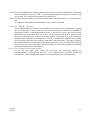
EUROPEAN NEW CAR ASSESSMENT PROGRAMME
(Euro NCAP)
SIDE IMPACT
TESTING PROTOCOL
Version 5.1
June 2011
Copyright ©Euro NCAP - This work is the intellectual property of Euro NCAP. Permission is granted for this material
to be shared for non-commercial, educational purposes, provided that this copyright statement appears on the
reproduced materials and notice is given that the copying is by permission of Euro NCAP. To disseminate otherwise
or to republish requires written permission from Euro NCAP.
Version 5.1
June 2011
Preface
Where text is contained within square brackets this denotes that the procedure being discussed is
currently being trialled in Euro NCAP. Its incorporation in the Test Protocol will be reviewed at a
later date.
During the test preparation, vehicle manufacturers are encouraged to liaise with the laboratory
and to check that they are satisfied with the way cars are set up for testing. Where a manufacturer
feels that a particular item should be altered, they should ask the laboratory staff to make any
necessary changes. Manufacturers are forbidden from making changes to any parameter that will
influence the test, such as dummy positioning, vehicle setting, laboratory environment etc.
It is the responsibility of the test laboratory to ensure that any requested changes satisfy the
requirements of Euro NCAP. Where a disagreement exists between the laboratory and
manufacturer, the Euro NCAP secretariat should be informed immediately to pass final judgment.
Where the laboratory staff suspect that a manufacturer has interfered with any of the set up, the
manufacturer's representative should be warned that they are not allowed to do so themselves.
They should also be informed that if another incident occurs, they will be asked to leave the test
site.
Where there is a recurrence of the problem, the manufacturer‟s representative will be told to
leave the test site and the Secretary General should be immediately informed. Any such incident
may be reported by the Secretary General to the manufacturer and the person concerned may not
be allowed to attend further Euro NCAP tests.
Version 5.1
June 2011
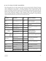
In addition to the settings specified in this protocol, the following information will be required
from the manufacturer of the car being tested in order to facilitate the vehicle preparation. A
vehicle handbook should be provided to the test laboratory prior to preparation where available.
Manufacturer-Specified Settings
Adjustment
Frontal Impact
Fuel Tank Capacity
Unladen Kerb Weight
Tyre Pressures
Seat Back/Torso Angle
95th Percentile Male Seating Position
Seat Base Tilt
Rear seat position (where applicable)
Child Seat Make/Model
Door Handle Pull Angle
50th Percentile Seat belt anchorage position
Seat Lumbar Support Position
Engine Running
Driver Airbag Removal Instructions
Side Impact
As Front, in addition:
Height of non-adjustable version of front seat
R-Point
Version 5.1
June 2011
Section Reference
Manufacturer's Handbook
Manufacturer's Handbook
Manufacturer's Handbook
Section 6.1
Section 6.1
Manufacturer's Handbook Section 6.4
Section 9.4
Section 6.0
Section 5.2
Section 1.4
Contents
Page No.
Side Impact
1 VEHICLE PREPARATION
1.1 Unladen Kerb Mass
1.2 Reference Loads
1.3 „R‟ Point
1.4 Vehicle Preparation
1.5 Vehicle Markings
1
1
1
2
2
2
2 DUMMY PREPARATION AND CERTIFICATION
2.1 General
2.2 Certification
2.3 Additions and Modifications to the ES-2 Dummy
2.4 Dummy Clothing and Footwear
2.5 Dummy Test Condition
2.6
Post Test Dummy Inspection
4
4
4
4
4
4
6
3 INSTRUMENTATION
3.1 Dummy Instrumentation
3.2 Vehicle Instrumentation
3.3 Trolley and Barrier Instrumentation
7
7
9
9
4 CAMERA LOCATIONS
10
5 PASSENGER COMPARTMENT ADJUSTMENTS
5.1 Determination of and Setting the Fore/aft Position of the Seat.
5.2 Setting the Seat Base Vertical, Tilt and Lumbar Positions
5.3 Setting the Steering Wheel Horizontal Adjustment
5.4 Setting the Steering Wheel Vertical Adjustment
5.5
Setting the rear seat (if adjustable).
12
14
14
14
15
15
6 DUMMY POSITIONING AND MEASUREMENTS
6.1 Determine the H-point of the driver‟s seat
6.2 Dummy Installation
6.3 Dummy Placement
6.4 Child Restraint System (CRS) Installation and Child Dummy Placement
6.5 Dummy Positioning Measurements
16
16
17
17
18
22
7 BARRIER AND TROLLEY
7.1 Trolley Preparation
7.2 Trolley Markings
23
23
23
8 STILL PHOTOGRAPHY
24
9 TEST PARAMETERS
25
Version 5.1
June 2011
9.1
9.2
9.3
9.4
9.5
Speed
Post-Impact Braking
Alignment
Door Opening Force
Dummy Removal
25
25
25
25
26
10 CALCULATION OF INJURY PARAMETERS
10.1 Head
10.2 Ribs
10.3 Abdomen
10.4 Pelvis
10.5 Pubic Symphysis
10.6 Child Dummies
27
28
28
29
29
29
29
Appendix I
1 IMPACTOR SPECIFICATIONS
30
31
Version 5.1
June 2011
1 VEHICLE PREPARATION
1.1 Unladen Kerb Mass
Note: EC directive 96/27/EC defines the Unladen Mass of the vehicle as the mass with 90% fuel
but all other fluids at maximum capacity.
1.1.1 The capacity of the fuel tank will be specified in the manufacturer‟s booklet. This volume
will be referred to throughout as the “fuel tank capacity”.
1.1.2 Syphon most of the fuel from the tank and then run the car until it has run out of fuel.
1.1.3 Refill the tank with fuel, water or other ballast to a weight equivalent to 90% of its fuel
tank capacity of fuel.
1.1.4 Check the oil level and top up to its maximum level if necessary. Similarly, top up the
levels of all other fluids to their maximum levels if necessary.
1.1.5 Ensure that the vehicle has its spare wheel on board along with any tools supplied with the
vehicle. Nothing else should be in the car.
1.1.6 Ensure that all tyres are inflated according to the manufacturer‟s instructions for half load.
1.1.7 Measure the front and rear axle weights and determine the total weight of the vehicle. The
total weight is the „unladen kerb mass‟ of the vehicle. Record this mass in the test details.
1.1.8 Measure and record the ride heights of the vehicle at all four wheels
1.2 Reference Loads
1.2.1 Place both front seats in their mid-positions, this may not be the same as the final test
position. If there is no notch at this position, set the seat in the nearest notch rearward (this
will be done more completely in Section 5).
1.2.2 Place weights equivalent to an ES-2 test dummy (80kg) in the front driver‟s seating
position.
1.2.3 Place weights in the luggage compartment of the vehicle until the total vehicle mass (sum
of front and rear axle masses) is 100kg more than the unladen kerb mass (from Section
1.1.7). The normal luggage compartment should be used i.e. rear seats should not be
folded to increase the luggage capacity. Spread the weights as evenly as possible over the
base of the luggage compartment. If the weights cannot be evenly distributed, concentrate
weights towards the centre of the compartment.
1.2.4 In the child restraints recommended by the manufacturer, place masses equivalent to a 1½
and a 3 year old child dummy on the rear drivers seat and passenger seat respectively
(11kg and 15kg). If the child restraints are not available at this time then default masses of
3kg should be added to the dummy masses.
1.2.5 For two seater vehicles only, the mass of child dummies and child seats shall not be
included in the reference load. For vehicles with limited rear space, child seats and
dummies shall be included in the reference load.
1.2.6 Roll the vehicle back and forth to „settle‟ the tyres and suspension with the extra weight on
board. Weigh the front and rear axle weights of the vehicle. These loads are the “axle
reference loads” and the total weight is the “reference mass” of the vehicle.
1.2.7 Record the axle reference loads and reference mass in the test details.
1.2.8 Measure and record the ride-heights of the vehicle at the point on the wheel arch in the
same transverse plane as the wheel centres. Do this for all four wheels.
1.2.9 Remove the weights from the luggage compartment and from the front and rear seats.
Version 5.1
June 2011
1
1.3 ‘R’ Point
To measure vehicle dimensions and to apply markers, a pointer used to measure co-ordinates in
three dimensions will be used.
1.3.1 The location of the R point relative to some part of the vehicle structure will have been
provided by the manufacturer. Determine the position of this point.
1.3.2 Mark a point on the driver‟s side of the car which has X (longitudinal) co-ordinate not
more than 1mm different to the theoretical R point location.
1.3.3 Draw a vertical line through the R-Point and mark it clearly „R‟.
1.3.4 Mark points along the side of the vehicle which have the same X co-ordinates as the „R‟
point. Continue these points onto the roof of the vehicle. The points should all lie in the
same vertical transverse plane as the „R‟ point.
1.3.5 Using a piece of sticky tape in a colour to contrast with the body-colour, join the points
with one edge of the tape. Mark clearly on the tape which of its edges aligns with the „R‟
point. This edge may be used to assess the alignment of the barrier with the „R‟ point.
1.4 Vehicle Preparation
Care should be taken during vehicle preparation that the ignition is not switched on with the
battery or airbag disconnected. This will result in an airbag warning light coming on and the airbag
system will need to be reset.
1.4.1 Remove the carpeting, spare wheel and any tools or jack from the luggage area. The spare
wheel should only be removed if it will not affect the crash performance of the vehicle.
1.4.2 Ensure that the vehicle‟s battery is connected, if possible in its standard position. Check
that the dashboard light for the airbag circuit functions as normal.
1.4.3 Fit the on-board data acquisition equipment in the boot of the car. Also fit any associated
cables, cabling boxes and power sources.
1.4.4 Place weights equivalent to a ES-2 dummy (80kg) in the front driver‟s seat of the car (with
the front seats in their mid-positions).
1.4.5 In the child restraints recommended by the manufacturer, place masses equivalent to a 1½
and a 3 year old child dummy on the rear drivers seat and passenger seat respectively (11kg
and 15kg). If the child restraints are not available at this time then default masses of 3kg
should be added to the dummy masses.
1.4.6 Weigh the front and rear axle weights of the vehicle. Compare these weights with those
determined in Section 1.2.5
1.4.7 The total vehicle mass shall be within 1% of the reference mass (Section 1.2.5). Each axle
load shall be within the smaller of 5% or 20kg of its respective axle reference load (Section
1.2.5). If the vehicle differs from the requirements given in this paragraph, items may be
removed or added to the vehicle which has no influence on its structural crash
performance. The levels of ballast in the fuel tank (equivalent in mass to 90% capacity of
fuel) may also be adjusted to help achieve the desired axle weights. Any items added to
increase the vehicle weight should be securely attached to the car.
1.4.8 Repeat Sections 1.4.6 and 1.4.7 until the front and rear axle weights and the total vehicle
weight are within the limits set in 1.4.7. Record the final axle weights in the test details.
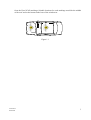
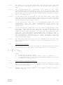
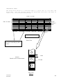
1.5 Vehicle Markings
1.5.1 Euro NCAP markings will be attached to the exterior of the vehicle in the following
locations; centre of the bonnet and on the front half of the roof of the vehicle. Refer to
figure 1.1. Areas marked with a dotted box are considered acceptable to place Euro NCAP
markings within.
1.5.2 Test house logos may be added to the vehicle provided that they do not detract attention
Version 5.1
2
June 2011
from the Euro NCAP markings. Suitable locations for such markings would be the middle
of the roof and on the bonnet at the base of the windscreen.
Figure 1.1
Version 5.1
June 2011
3
2 DUMMY PREPARATION AND CERTIFICATION
2.1 General
2.1.1 An ES-2 test dummy shall be used in the front driver‟s position. It shall conform to the
requirements given in document TRANS-WP29-GRSP-2002-11e, which was presented to
GRSP on 13th – 17th May 2002 (thirty first session).
2.1.2 A TNO/Ogle P1½ child dummy, in a suitable Child Restraint System (CRS) (see Section
6.4), shall be used in the rear driver side seating position.
2.1.3 A TNO P3 child dummy, in a suitable CRS (see Section 6.4), shall be used in the rear
passenger side seating position.
2.2 Certification
Full details of the ES-2 certification requirements are available in the document mentioned in
Section 2.1.1, TRANS-WP29-GRSP-2002-11e, and the procedures followed are set out in the ES2 User Manual. Details of the certification procedure for P3 and P1½ dummies are available in the
user documentation. No manufacturer shall have access to any pre-test information
regarding
any of the test equipment to be used by Euro NCAP, or be permitted to influence its
selection
in any way.
2.2.1 The ES-2 dummy should be re-certified after every THREE impact tests.
2.2.2 The TNO P3 and P1½ child dummies shall be re-certified after every SIX impact tests (e.g.
3 frontal and 3 side impacts, or any combination of the two test types).
2.2.3 If an injury criterion reaches or exceeds its normally accepted limit (eg HIC of 1000) then
that part should be re-certified.
2.2.4 If any part of a dummy is broken in a test then the part shall be replaced with a fully
certified component.
2.2.5 Copies of the dummy certification certificates will be provided as part of the full report for
a test.
2.3 Additions and Modifications to the ES-2 Dummy
2.3.1 The ES-2 dummy neck shall be fitted only with neck buffer 80 shore colour blue, part
number: E2.BBC. The assembly must meet the certification procedure detailed below.
2.4 Dummy Clothing and Footwear
2.4.1 ES-2
2.4.1.1 The dummy will be clothed in an ES-2 rubber „wet-suit‟, covering the shoulders, thorax,
upper parts of the arms, abdomen and lumbar spine and the upper part of the pelvis. This
rubber suit will act as a nominal „skin‟ for the dummy torso.
2.4.1.2 The dummy will be clothed with formfitting, calf-length, cotton stretch pants and shoes.
2.4.2 Child Dummies
2.4.2.1 Each child dummy shall be fitted with close-fitting stretch clothing suitable for an infant of
an appropriate age.
2.5 Dummy Test Condition
2.5.1 Dummy Temperature
2.5.1.1 The dummy shall have a stabilised temperature in the range of 18oC to 26oC.
2.5.1.2 A stabilised temperature shall be obtained by soaking the dummy in temperatures that are
within the range specified above for at least 5 hours prior to the test.
2.5.1.3 Measure the temperature of the dummy using a recording electronic thermometer placed
Version 5.1
June 2011
4
inside the dummy‟s flesh. The temperature should be recorded at intervals not exceeding
10 minutes.
2.5.1.4 A printout of the temperature readings is to be supplied as part of the standard output of the
test.
2.5.2 Dummy Joints
2.5.2.1 Stabilise the dummy temperature by soaking in the required temperature range for at least 5
hours.
2.5.2.2 Set the torque on the shoulder screws to obtain a 1-2g holding force of the arm on its pivot.
2.5.2.3 For adjustable joints in the legs, the tensioning screw or bolt which acts on the constant
friction surfaces should be adjusted until the joint can just hold the adjoining limb in the
horizontal. When a small downward force is applied and then removed, the limb should
continue to fall.
2.5.2.4 The dummy joint stiffnesses should be set as close as possible to the time of the test and, in
any case, not more than 24 hours before the test.
2.5.2.5 Maintain the dummy temperature within the range 18 to 26C between the time of setting
the limbs and up to a maximum of 10 minutes before the time of the test.
2.5.3 Dummy painting and marking
2.5.3.1 The dummies should have masking tape placed on the areas to be painted using the size
table below. The tape should be completely covered with the following coloured paints.
The paint should be applied close to the time of the test to ensure that the paint will still be
wet on impact.
ES-2
Head (Paint tape outline only)
Shoulder/Arm
Top Rib
Mid Rib
Bottom Rib
Abdomen
Pelvis
Child dummies
Top of Head
Head-band thirds (colours from left to right)
Red
Blue
Red
Yellow
Green
Red
Orange
Blue
Red, Yellow, Green
NOTE: The tape should be completely covered with the coloured paints specified, with the
exception of the ES-2 Head which should have only the outer edge of the tape painted. Adhesive
target markers should be attached to the top/rear of the child dummy‟s head in order to aid the
assessment of the child head containment.
Version 5.1
June 2011
5
Tape Sizes:
ES-2
Head
= 100mm square, centreline of head with lower edge at C of G.
Shoulder/Arm = 25mm x 150mm, starting at bottom edge of shoulder fixing hole.
Ribs
= 150mm strip, starting at the rearmost accessible point at seat back.
Abdomen
= 50 x 50mm square
Pelvis
= 50mm x 100mm, centred on hip joint point.
Child Dummies
Top of Head = 50 x 50mm square
Headbands
= 25mm wide, widest circumference remaining at eyebrow level at front,
extending to the head C of G at each side.
2.6
2.6.1
Post Test Dummy Inspection
The dummy should be visually inspected immediately after the test. Any lacerations of the
skin or breakages of the dummy should be noted in the test details. The dummy may have
to be re-certified in this case. Refer to Section 2.2.
Version 5.1
June 2011
6
3 INSTRUMENTATION
All instrumentation shall be calibrated before the test programme. The Channel Amplitude Class
(CAC) for each transducer shall be chosen to cover the Minimum Amplitude listed in the table. In
order to retain sensitivity, CACs which are orders of magnitude greater than the Minimum
Amplitude should not be used. A transducer shall be re-calibrated if it reaches its CAC during any
test. All instrumentation shall be re-calibrated after one year, regardless of the number of tests for
which it has been used. A list of instrumentation along with calibration dates should be supplied
as part of the standard results of the test. The transducers are mounted according to procedures laid
out in SAE J211. The sign convention used for configuring the transducers is stated in SAE J211
(1995).
3.1 Dummy Instrumentation
The ES-2 dummy to be used shall be instrumented to record the channels listed below.
ES-2
Location
Parameter
Minimum
Amplitude
Head
Accelerations, Ax Ay Az
250g
3
Shoulder
Forces, Fx Fy Fz
8kN
3
Thorax T1
Accelerations, Ax Ay Az
200g
3
Thorax T12
Acceleration, Ay
200g
1
Ribs - Upper
Middle
Lower
Acceleration, Ay
700g
3
Deflection, Drib
90mm
3
Forces, Fy
5kN
3
Forces, Fx Fy
5kN
Abdomen - Front
Middle
Rear
Backplate
No of channels
4
Moments, My Mz
200Nm
Forces, Fx Fy
5kN
Moments, Mx My
300Nm
Pelvis
Accelerations, Ax Ay Az
150g
3
Pubic Symphysis
Force, Fy
20kN
1
Femurs (L & R)
Forces, Fx Fy Fz
22kN
6
T12
Version 5.1
June 2011
4
7
Moments, Mx My Mz
350Nm
6
Total Channels per Dummy
43
1 x ES-2
43
TNO P3
Location
Parameter
Minimum
Amplitude
Head
Accelerations, Ax Ay Az
150g
3
Chest
Accelerations, Ax Ay Az
150g
3
No of channels
Total Channels per Dummy
6
1 x TNO P3 Dummy
6
TNO P1½
Location
Parameter
Minimum
Amplitude
Head
Accelerations, Ax Ay Az
150g
3
Chest
Accelerations, Ax Ay Az
150g
3
Version 5.1
June 2011
No of channels
Total Channels per Dummy
6
1 x TNO P1½ Dummy
6
8
3.2 Vehicle Instrumentation
3.2.1 The vehicle is to be fitted with an accelerometer on the unstruck B-post. The accelerometer
is to be fitted in the lateral direction (Ay).
3.2.2 Remove carpet and the necessary interior trim to gain access to the sill directly below the
B-post.
3.2.3 Securely attach a mounting plate for the accelerometer horizontally on to the sill.
3.2.4 Fix the accelerometer to the mounting plate. Ensure the accelerometer is horizontal to a
tolerance of ±5 degrees.
VEHICLE
Location
Parameter
Minimum
Amplitude
B-Post (unstruck)
Acceleration, Ay
150g
No of channels
1
Total Channels per Vehicle
1
3.3 Trolley and Barrier Instrumentation
3.3.1 The trolley is to be fitted with an accelerometer at its Centre of Gravity. The accelerometer
is to be fitted in the fore/aft direction (Ax). (See Section 7)
TROLLEY
Location
Parameter
Minimum
Amplitude
Trolley C of G
Acceleration, Ay
150g
No of channels
1
Total Channels per Trolley
1
TOTAL CHANNELS
1x Driver ES-2
43
1x TNO P3
6
1x TNO P 1½
6
1x Vehicle
1
1x Trolley
1
TOTAL
57
Version 5.1
June 2011
9
4 CAMERA LOCATIONS
Set up high speed film cameras according to the following diagrams
2
1, 4, 5
6
3
7
8
Camera
Version 5.1
June 2011
Camera Type
Shot Content
10
No.
1
>/= 500 fps high speed
Front view of vehicle and trolley (wide)
2
>/= 500 fps high speed
Rear view of vehicle and trolley (wide)
3
>/= 500 fps high speed
Child head containment, onboard
4
>/= 500 fps stills camera
Front view of vehicle and trolley (wide)
5
>/= 500 fps stills camera
Backup for 4 (optional)
6
>/= 500 fps high speed
Front view of driver and impact point (tight)
7
>/= 500 fps high speed
Child head containment, onboard
8
>/= 500 fps high speed
Plan view of car and trolley (tight)
4.1
4.2
4.3
4.4
The Euro NCAP High Speed Digital Film Specifications are contained in a separate
document.
Lens sizes should be chosen appropriately in order to achieve the required shot
content/intention. In order to prevent view distortion, a minimum lens size of 9mm is
applicable. Please note for view number 7 the passenger side headrest should be removed if
possible.
For forward facing CRS, cameras 3 and 7 shall face toward the rear of the vehicle to
capture head containment. For rearward facing CRS, the camera should face toward the
front of the vehicle to capture head containment. The positioning of onboard cameras will
be dependent upon the body type and size of test vehicle.
When attaching onboard cameras, the vehicle manufacturer should be consulted to ensure
that no damage is caused to the vehicle that would influence the impact performance or
interfere with any airbags during deployment. Where additional equipment is added, the
mass shall be offset when achieving the final test weight.
Version 5.1
June 2011
11
5 PASSENGER COMPARTMENT ADJUSTMENTS
Adjustment
Required Setting
Notes
Methods
Set
to
first
notch
rearwards of mid position
if not lockable at mid
position
Permissible Up to mid
position
If only adjustable seats
available, set to midposition
See Section 5.1
See Section 6.1
Seat Fore/Aft
Mid position as defined in 5.1
Seat Base Tilt
Manufacturer's design position
Seat Height
Same height as non-adjustable
version of front seat
Seat Back Angle (as defined
by torso angle)
Seat Lumbar Support
Front Head Restraints
Manufacturer's design position
Otherwise 25to Vertical
Head Restraint Tilt Angle
Steering wheel - vertical
Steering wheel - horizontal
Rear Head Restraints
Manufacturer's design position
Top surface level with Centre of
Gravity of dummy head
Manufacturer's design position
Mid position
Mid position
Remove or Lowest
Otherwise fully retracted
Place at highest setting if
unable to align with CofG
Otherwise mid position
Rear Seat Fore/Aft
Mid position
Rear Seat Facing
Arm-rests (Front seats)
Forwards
Lowered position
Arm-rests (Rear seats)
Glazing
Stowed position
Front - Raised
Rear - Raised
In the neutral position
Disengaged
Normal position of rest
Closed, not locked
Raised
Stowed position
Normal position of use
Initially, manufacturer‟s
percentile design position
Gear change lever
Parking Brake
Pedals
Doors
Roof
Sun Visors
Rear view mirror
Seat belt anchorage (where
adjustable)
See Section 5.2
See Section 5.4
See Section 5.3
Unless
instructed
otherwise
by
the
manufacturer
Vehicle manufacturer to
supply details of seat
position contained in
handbook
when
no
handbook is available at
the time of test
See Section 5.5.1
See Section 5.5.1
May be left up if dummy
positioning does not
allow lowering
Where applicable
50th
If no design position then
set to mid position, or
nearest notch upwards
Adjustments not listed will be set to mid-positions or nearest positions rearward, lower or outboard. If both an
Version 5.1
June 2011
12
adjustable and non-adjustable seat is fitted, the adjustable seat should be set to the same position as the non-adjustable
version.
Version 5.1
June 2011
13
5.1 Determination of and Setting the Fore/aft Position of the Seat.
5.1.1 The manufacturers seat fore/aft position which corresponds to the 95th percentile male
seating position will have been provided.
5.1.2 Place a mark on the moving part of seat runner close to the unmoving seat guide
5.1.3 Move the seat to its most forward position of travel.
5.1.4 Mark the unmoving seat guide in line with the mark on the seat runner. This corresponds to
the seat in its most forward position.
5.1.5 Move the seat to the position of its travel provided for the 95th percentile male.
5.1.6 Mark the unmoving seat guide in line with the mark on the seat runner. This corresponds to
the 95th percentile male‟s seating position.
5.1.7 Measure the distance between the forwards and rearwards marks. Place a third mark on the
seat guide mid-way between the forwards and rearwards marks.
5.1.8 Move the seat so that the mark on the seat runner aligns with the mark on the seat guide.
5.1.9 Lock the seat at this position. Ensure that the seat is fully latched in its runners on both
sides of the seat. The seat is now defined as being at its „mid seating position‟. The vehicle
will be tested with the seat in this position.
5.1.10 If the seat will not lock in this position, move the seat to the first locking position that is
rear of the mid seating position. The vehicle will be tested with the seat in this position.
5.2 Setting the Seat Base Vertical, Tilt and Lumbar Positions
5.2.1 If the seat is adjustable for height, the manufacturer will be asked whether the vehicle is
made with non-adjustable seats for driver or passenger. If this is the case, the manufacturer
will be asked what the height of the H-point is for the non-adjustable version.
5.2.2 Using the procedure described more fully in Section 6.1, sit the H-point manikin in the seat
5.2.3 Adjust the height of the seat until the H-point of the manikin is at the same height as that
given by the manufacturer‟s information.
5.2.4 If the vehicle is not available with non-adjustable seat height, set the seat to its middle
position.
5.2.5 If the seat base is adjustable for tilt it may be set to any angle from the flattest to its mid
position according to the manufacturer‟s preference. The same seat tilt setting must be used
for frontal and side impact.
5.2.6 Seat Lumbar Setting. If the seat back is adjustable for lumber support it should be set to the
fully retracted position, unless the manufacturer specifies otherwise or the dummy prevents
this.
The settings for the passenger seat should be as near as possible to being the same as that of
the driver’s seat.
5.3 Setting the Steering Wheel Horizontal Adjustment
5.3.1 Choose a part of the facia that is adjacent to the steering column and can be used as a
reference.
5.3.2 Move the steering wheel to the most forward position of its travel
5.3.3 Mark the steering column in line with an unmoving part of the facia. This corresponds to
the most forward travel of the steering wheel.
5.3.4 Move the steering wheel to the most rearwards position of its travel
Version 5.1
June 2011
14
5.3.5
5.3.6
5.3.7
5.3.8
Mark the steering column in line with an unmoving part of the facia. This corresponds to
the most rearwards travel of the steering wheel.
Measure the distance between the forwards and rearwards marks on the steering column.
Place a third mark on the steering column mid-way between the forwards and rearwards
marks. This corresponds to the centre of travel of the steering wheel.
Move the steering wheel so that the mark on the steering column aligns with the facia.
Lock the steering column at this position. The steering wheel is now in its mid-position of
travel. The vehicle will be tested with the steering wheel in this position.
5.4 Setting the Steering Wheel Vertical Adjustment
5.4.1 A method that is in principle the same as Section 5.3 should be used to find and set the
steering wheel vertical adjustment to the mid position. It is unlikely that the same part of
the facia used during the setting procedures for the horizontal adjustments could be used
for the vertical adjustment. Care should be taken to avoid unintentional adjustment of the
horizontal setting during the vertical adjustment procedure.
5.5
Setting the rear seat (if adjustable).
5.5.1 If the vehicle rear seat position is adjustable put it in the same fore/aft position as that used
in the frontal with the same seat back angle.
Version 5.1
June 2011
15
6 DUMMY POSITIONING AND MEASUREMENTS
The following chapter deals with all aspects of seating the dummy in the vehicle to be tested. A
general timetable of the complete procedure is set out below:Timetable
When this is done
1. Determine the H-point
of the driver‟s seat
Before test day
2.Dummy installation
(on boards)
Before test day
3. Dummy placement
Test day
4.Dummy positioning
Test day
5. Dummy positioning
measurements
Test day - after vehicle has
been positioned for test
6.1 Determine the H-point of the driver’s seat
The device to be used is the H-point machine as described in SAE J826
If the seat is new and has never been sat upon, a person of mass 75 ± 10kg should sit on the seat
for 1 minute twice to flex the cushions.
The seat shall have been at room temperature and not been loaded for at least 1 hour previous to
any installation of the machine.
6.1.1
Set the seat back so that the torso of the dummy is as close as possible to the
manufacturer‟s recommendations for normal use. In absence of such recommendations, an
angle of 25 degrees towards the rear from vertical will be used.
6.1.1.1 The driver and passenger seatback angle and seat base shall be set to the same position.
6.1.1.2 Where one seat is height adjustable and the other is fixed, the relative angle between the
seat back and the ground should be the same for both seats.
6.1.1.3 Where both seats are adjustable, the manufacturer is asked to supply recommended
settings. These should not differ from the nominal settings by more than a reasonable
amount. In any of the above situations, the manufacturer may provide convincing
information that the seat adjustments should be different from that specified here. If so the
fully supported request to vary the set up should be made to the Secretariat.
6.1.2 Place a piece of muslin cloth on the seat. Tuck the edge of the cloth into the seat pan/back
join, but allow plenty of slack.
6.1.3 Place the seat and back assembly of the H-point machine on the seat at the centre line of
the seat
6.1.4 Set the thigh and lower leg segment lengths to 401 and 414mm respectively
6.1.5 Attach lower legs to machine, ensuring that the transverse member of the T-bar is parallel
Version 5.1
16
June 2011
6.1.6
6.1.7
6.1.8
6.1.9
6.1.10
6.1.11
6.1.12
6.1.13
6.1.14
6.1.15
6.1.16
6.1.17
6.1.18
6.1.19
6.1.20
to the ground.
Place right foot on undepressed accelerator pedal, with the heel as far forwards as
allowable. The distance from the centre line of the machine should be noted.
Place left foot at equal distance from centre line of machine as the right leg is from centre
line. Place foot flat on footwell.
Apply lower leg and thigh weights
Tilt the back pan forwards to the end stop and draw the machine away from the seat back.
Allow the machine to slide back until it is stopped by contacting the seat back.
Apply a 10kg load twice to the back and pan assembly positioned at the intersection of the
hip angle intersection to a point just above the thigh bar housing.
Return the machine back to the seat back.
Install the right and left buttock weights.
Apply the torso weights alternately left and right.
Tilt the machine back forwards to the end stop and rock the pan by 5 degrees either side of
the vertical. The feet are NOT to be restrained during the rocking. After rocking the T-bar
should be parallel to the ground.
Reposition the feet by lifting the leg and then lowering the leg so that the heel contacts the
floor and the sole lies on the undepressed accelerator.
Return the machine back to the seat back.
Check the lateral spirit level and if necessary apply a lateral force to the top of the machine
back, sufficient to level the seat pan of the machine.
Adjust the seat back angle to the angle determined in 6.1.1, measured using the spirit level
and torso angle gauge of the H-point machine. Ensure that the torso remains in contact with
the seat back at all times. Ensure that the machine pan remains level at all times.
Measure and record in the test details the position of the H-point relative to some easily
identifiable part of the vehicle structure.
6.2 Dummy Installation
It is the intention that the dummy should not be left to sit directly on the seat for more than 2 hours
prior to the test. It is acceptable for the dummy to be left in the vehicle for a longer period,
provided that the dummy is not left in overnight or for a similarly lengthy period.
If it is known that the dummy will be in the vehicle for a time longer than 2 hours, then the dummy
should be sat on plywood boards placed over the seat. This should eliminate unrealistic
compression of the seat.
6.3 Dummy Placement
If the vehicle has only two side doors, it may be necessary to fit the child restraint systems and
child dummies (Section 6.4) before setting up the ES-2 dummy in the front seat.
6.3.1 H-point
Note that the H-point of the ES-2 dummy is situated 21mm forward of that of the H-point
determined by the H-point manikin (Section 6.1). The H-point of the manikin is indicated by
‘Hm’ on the H-point back plate of the dummy.
6.3.1.1 Position the dummy in the seat, with its back against the seat and its centreline coinciding
with the seat centreline.
6.3.1.2 Manoeuvre the dummy until its "Hm" position is in a circle with a radius of 10 mm round
the H-point of the H-point Manikin as determined in Section 6.1.
6.3.2 Alignment
Version 5.1
June 2011
17
Visually check that the dummy sits square and level in the seat before taking any measurements of
the H-point position.
6.3.3 Legs and Feet
6.3.3.1 Position the left foot perpendicular to the lower leg with its heel on the floorpan in a
transverse line with the heel of the right foot.
6.3.3.2 Carefully position the dummy‟s right foot on the undepressed accelerator pedal with the
heel resting as far forward as possible on the floorpan.
6.3.3.3 Measure the separation of the inside surfaces of the dummy‟s knees and adjust until they
are 150±10mm apart from each other.
6.3.3.4 If possible within these constraints, place the thighs of the dummy on the seat cushion.
6.3.3.5 Check again the position of the H-point, the levelness of the pelvis and the squareness of
the dummy in the seat. If everything is in position, set the arms.
6.3.4 Arms
The arms of the ES-2 dummy have click-stops corresponding to fixed angles between the
torso reference line and the arms.
6.3.4.1 Move both arms of the dummy until they have clicked at those positions corresponding to
40 angle between the arms and the torso reference line.
6.3.5 Seat belt
6.3.5.1 Where possible, initially position the upper seat belt anchorage in the manufacturers 50 th
percentile design position. If no design position is provided, set the adjustable upper seat
belt anchorage to the mid-position or nearest notch upward.
6.3.5.2 Carefully place the seat belt across the dummy and lock as normal.
6.3.5.3 Remove the slack from the lap section of the webbing until it is resting gently around the
pelvis of the dummy. Only minimal force should be applied to the webbing when removing
the slack. The route of the lap belt should be as natural as possible.
6.3.5.4 Place one finger behind the diagonal section of the webbing at the height of the dummy
sternum. Pull the webbing away from the chest horizontally forward and allow it to retract
in the direction of the D-loop using only the force provided by the retractor mechanism.
Repeat this step three times, only.
6.3.5.5 After following the above steps, the seatbelt should lie in a natural position across the
dummy sternum and shoulder clavicle. Where this is not the case, for example the belt is
close to or in contact with the neck or the belt is above the shoulder rotation adjustment
screw, and the upper belt anchorage is adjustable the anchorage should be lowered and
steps 6.3.5.3 and 6.3.5.4 repeated.
6.3.5.6 The upper anchorage should be lowered by a sufficient amount to ensure a natural belt
position following the repetition of .steps 6.3.5.3 and 6.3.5.4 repeated. This may require
multiple attempts.
6.3.5.7 Once the belt is positioned the location of the belt should be marked across the dummy
chest to ensure that no further adjustments are made. Mark also the belt at the level of the
D-loop to be sure that the initial tension is maintained during test preparation.
6.3.5.8 Measure the vertical distance between the dummy nose and the diagonal webbing.
6.3.5.9 Measure the horizontal distance between the diagonal webbing and the door/window.
6.4 Child Restraint System (CRS) Installation and Child Dummy Placement
Two CRS‟s are to be fitted in the rear seat, one suitable for a 3 year old child, the other for an 18
Version 5.1
June 2011
18
month old infant. Each will be the system recommended by the manufacturer for that size of child.
The type of system to be fitted will be determined from the manufacturer. The type of system to be
fitted will be determined from the manufacturer. There must be sufficient space between the
vehicle interior and CRS to allow for proper installation of the restraint without the need for
excessive force. The restraint must not be prevented from sitting in its „normal‟ orientation, for
example the vehicle interior trim must not cause any obstruction. The dummies must also be
allowed to rest in a „normal‟ position.
6.4.1
6.4.2
6.4.3
Read the relevant sections of the vehicle handbook and the instructions provided with the
child restraint. This is to identify any special features of either the vehicle or the child
restraint that are intended to improve performance or may influence installation.
Instructions on tightening of the adult seat belt around the child restraint should be noted,
but the installation itself should follow the procedure below.
Calibrate the seat belt tension load cells to be used in the CRS installation process at the
required load reading i.e. 50N for lap and diagonal installations and 75N for lap belt
applications directly before beginning the installation procedure.
Ensure that the seat and belt anchorage positions are as defined in section 5.5. In the case
of an adult seat belt that is capable of being switched from an emergency locking retractor
(ELR) to an automatic locking retractor (ALR) follow clear advice, obvious to the user,
about how the ALR feature should be used on any labels associated with the seat belt
(information given in the handbook will be ignored as reading of the handbook cannot be
assumed for all users).
6.4.4 For Integral Harness Systems
6.4.4.1 Install the child restraint and place the dummy within it. Place the 2.5cm thick and 6cm
wide
flexible spacer between the back of the manikin and the back of the child restraint. The
lower end of the spacer should be at the height of the manikin‟s hip joint. Adjust the
harness restraining the child in accordance with the manufacturer‟s instructions, but to a
tension of 250 +/-50N above the frictional adjuster force. The angle of pull on the webbing
should be as indicated in the fitting instructions.
6.4.4.2 Release the harness buckle, remove the spacer, refasten the harness and push the dummy
towards the seat back. Arrange the slack within the integral harness so that it is evenly
distributed. Make sure the dummy head is upright, and the legs are parallel. Raise the
dummy feet and allow them to fall lightly into a stable resting position. Place the dummy‟s
hands so that they are resting on the top of the thighs and tape them lightly in position
using a weak paper tape.
6.4.4.3 In the case of a rearward facing restraint, use weak paper tape to locate the dummy head
relative to the back of the child restraint. The intention is to prevent dummy displacement
under acceleration during the vehicle run-up to the barrier. The tape should be weak
enough to break on impact of the vehicle with the barrier.
6.4.5
For Integral Harness Systems Installed With a 3 Point Seat Belt, With No Lock Off or Lock
Off Design That Can Be Released To Give No Friction During Installation
6.4.5.1 Engage the adult seat belt buckle, fit one load cell outboard on the lap section of the adult
belt and one on the free webbing of the diagonal section between the child restraint and the
pillar loop. Establish a tension of 50N +/-5N in both the lap and diagonal sections of the
Version 5.1
19
June 2011
adult belt webbing. Apply lock-off devices if available. If the design of the CRS is such
that tension is maintained within the lap and diagonal sections of webbing, remove the load
cell on the free section of diagonal webbing. However, if removal of the diagonal belt load
cell changes the installation tension of the belt, leave the load cell in place. Disconnect any
electrical leads and stow them ready for impact.
6.4.5.2 Draw all remaining webbing off the inertia reel of the adult seat belt and allow it to retract
slowly under the influence of its own retraction mechanism. If it is the intention for the
system not to be activated for the test then draw all the webbing from the reel and allow it
to fully retract, prior to the installation of the child seats. Do not fully draw the webbing
from the reel after this procedure has been completed.
6.4.6
For Integral Harness Systems Installed With a 3 Point Seat Belt, With a Lock-Off Design
That Cannot Be Released To Give No Friction During Installation.
6.4.6.1 Place the diagonal belt load cell between the lock-off and the buckle tongue slot and leave
it in position during the test. All other aspects of the installation are as per 6.4.5.
6.4.7
For Booster Seats In Which The Adult Belt Restrains The Child And In Which There Is A
Fixed Position Lock-Off.
6.4.7.1 Place the dummy in the seat with the spacer in position. Locate the diagonal load cell
between the lock-off and the buckle tongue slot, in a position where it will not interfere
with the dummy‟s arm movement. Locate the lap section load cell on the outboard adult
belt webbing. Establish a load of 50N +/-5N in both sections of the webbing. Leave the
load cells in position if their removal would alter the set-up tensions. Release the buckle,
remove the spacer and refasten the buckle. Set the dummy back in position as described
above in section 6.4.4 and check the webbing spooled on the inertia reel of the adult belt as
per section 6.4.5.2.
6.4.8
For Booster Seats In Which The Position Of The Lock-Off/Shoulder Belt Guide Is
Adjustable.
6.4.8.1 Optimise the position of the lock-off/shoulder belt guide before beginning the installation
process. For those systems in which the adult belt is used to restrain the child directly,
insert the spacer and continue the installation as described in 6.4.7. If the adult belt is used
to restrain the child restraint rather than the child itself install the load cells as described
above. After installation to the specified tensions operate any device that is specifically
designed to increase adult seat belt tension by use of a lever or cam type system or their
equivalent. The intention is to correctly credit special design features aimed at achieving
improved installation.
6.4.9 For Child Restraints Using An Impact Shield To Restrain The Child.
6.4.9.1 Install the dummy with the spacer and position the shield. Put load cells on lap and
diagonal sections of the seat belt. Establish a load of 50N +/-5N in both sections of the
webbing and, whilst manually clamping the webbing at the belt guides on the impact
shield, release the buckle and rotate the shield forward on the buckle side the minimum
amount necessary to allow removal of the spacer. Refasten the buckle, check that the shield
is positioned centrally, push the dummy back into the seat and continue with remaining
aspects of dummy positioning procedure described in sections 6.4.4.2 and 6.4.5.2. It will
probably be necessary to rest the dummy arms on the shield rather than the thighs as has
been suggested for other restraint types.
Version 5.1
20
June 2011
6.4.9.2 For seats installed with a static lap belt use one load cell on the non-buckle side of the adult
belt and establish a tension of 75N +/-5N equalised throughout the lap belt. Leave the load
cell in place if its removal would alter the set-up tension.
6.4.9.3 The time between child seat installation and impact should be subject to the same limits
that
are applied to adult dummies and should be kept as short as possible.
6.4.10 For “ISOFIX “ type seats
The installation protocol for these seats is under development. If any manufacturers request
the use of this type of seat the Euro NCAP Secretariat must be contacted for installation
instructions. Where a tensioning/ratchet device is provided to secure the child restraint
against the rear seats and/or floor etc, a force not exceeding 100N shall be applied in the
direction of the tensioning system‟s movement. Where a top tether is present it should be
attached to the anchorage, a maximum force of 50N 5N should be applied to the webbing
from a position where the user would be expected to install the tether. The angle of pull on
the webbing should be as indicated in the fitting instructions. Note: the 50N load is applied
directly to the free end of the tether, and intentionally does not take account of the internal
frictional characteristics of the adjuster.
6.4.11 For reclining child restraint systems
To set the seat angle firstly check the seat itself and instruction manual for
recommendations accompanying the seat. If no information is provided consult the
manufacturer. If the manufacturer makes no recommendation set to its mid position.
Version 5.1
June 2011
21
6.5 Dummy Positioning Measurements
The following measurements are to be recorded prior to the test after the dummy settling and
positioning procedures have been carried out.
N
Driver measurements
A
Head/roof panel
B
Nose point/windscreen joint
C
Nose point/centre of the steering
D*
Thorax strap/centre of the steering wheel
E
Hip-joint point/inside opening of the door
(horizontal)
F
Hip-joint point/inside opening of the door (vertical)
G
Knee/floor covering (vertical)
H
Head/side window pane (or padding)
J
Shoulder/window pane (or padding)
K
Elbow/door (or padding)
L
Pelvis/door (or padding)
M
Knee/door (or padding)
N
Belt webbing to door (horizontally)
* Horizontal distance from steering wheel centre
Version 5.1
June 2011
22
7 BARRIER AND TROLLEY
The trolley will be fitted with a deformable barrier face and ventilation frame conforming to the
specifications of Amendment 3, July 2003, Regulation ECE R95 (lateral collision protection). See
also Appendix I.
7.1 Trolley Preparation
7.1.1 A trolley should be used which has a wheelbase of 3000 ±10mm and a track at the front
and at the rear of 1500 ±10mm.
7.1.2 The trolley may be fitted with an emergency abort system. This is optional, the test facility
may elect to test without an abort system.
7.1.3 Inflate all tyres of the trolley to the same pressure.
7.1.4 Fix the deformable barrier to the front of the trolley such that its bottom edge is at a height
of 300mm +/- 5mm from the ground.
7.1.5 Mark a line along the vertical centreline of the barrier which may be used to check the
alignment of the barrier with the R point of the test vehicle.
7.1.6 Measure the wheelbase of the trolley, left and right
7.1.7 Determine the average wheelbase from Section 7.1.6 and record in the test details.
7.1.8 Record in the test details the track of the trolley at the front and at the rear.
7.1.9 Measure the weights at all four wheels and record in the test details. The total weight of
the trolley should be 950 ±20kg.
7.1.10 Calculate the fore/aft position of the centre of gravity from:
x = Wrear.Wheelbase/(Wrear + Wfront)
where x is the distance of the centre of gravity from the front axle, W rear and Wfront are the
rear and front axle weights from Section 7.1.9 and Wheelbase is the average determined in
Section 7.1.7.
The fore/aft centre of gravity should be 1000 ±10mm from the centre of the front axle.
7.1.11 Record the position of the centre of gravity in the test details.
7.1.12 Ensure that the weight distribution is as even as possible left to right.
7.1.13 Record in the test details the final weights measured at each of the wheels.
7.2 Trolley Markings
7.2.1 Euro NCAP markings will be stuck to the front of the trolley on both sides.
7.2.2 Test house logos may be added to the trolley provided that they do not detract attention
from the Euro NCAP markings.
Version 5.1
June 2011
23
8 STILL PHOTOGRAPHY
The following photographs will be taken pre and post-test unless otherwise indicated. Pre-test
photographs will be taken with the dummies in their final positions.
No.
1
2
3
4
5
6
7
8
9
10
11
12
13
14
15
16
17
18
19
View
Front view of barrier.
Side view of barrier.
Side view of barrier at 45 degrees to front.
Side view of barrier with vehicle, from front of vehicle.
Car RHS, with camera centred on B-post waist, showing full car.
Car RHS, with camera centred on B-post waist, showing the rear passenger
compartment.
Car RHS, with camera aimed at waist height, showing driver's compartment.
Car RHS at 45 degrees to rear.
Car RHS at 45 degrees to front.
Front view of car.
Car LHS, with camera centred on B-post waist, showing full car.
Car LHS, with camera centred on B-post waist, showing the rear passenger
compartment.
*To show position of all door latches and/or open doors.
Driver & seat through open driver‟s door to show driver compartment and position of seat
relative to the sill.
To show area immediately in front of driver.
To show child dummies and restraints through LHS rear door.
To show child dummies and restraints through RHS rear door.
*Car and barrier at rest at 45 degrees to front of car.
*Car and barrier at rest at 45 degrees to rear of car.
* Post-test only.
After Dummy Removal
20
*View through LHS front door of driver‟s door & paint marks from dummy ribs.
Note: The above photos are for a RHD car, for a LHD car camera locations will switch sides.
Version 5.1
June 2011
24
9 TEST PARAMETERS
An on-board data acquisition unit will be used. This equipment will be triggered by a contact plate at
the point of first contact (t=0) and will record digital information at a sample rate of 20kHz
(alternatively a sample rate of 10kHz may be used). The equipment conforms to SAE J211 (1995).
BEFORE THE TEST, ENSURE THAT THE LIVE BATTERY IS CONNECTED, A SINGLE
KEY IS IN THE IGNITION, THE IGNITION IS ON AND THAT THE AIRBAG LIGHT ON
THE DASHBOARD ILLUMINATES AS NORMAL (WHERE FITTED)
If the vehicle is fitted with a brake pedal retraction mechanism which requires a vacuum present in the
brake system, the engine may be ran for a predetermined time, specified by the manufacturer.
9.1 Speed
9.1.1
Measure the speed of the trolley as near as possible to the point of impact.
9.1.2
Record the actual test speed in the test details.
TARGET SPEED = 50km/h ± 1km/h
9.2 Post-Impact Braking
A method must be employed to eliminate secondary impacts between the barrier and the car. This may
be an emergency braking system on the trolley or other method but should be activated only after the
first impact is complete. Do NOT start the braking at the point of initial impact or the trolley will be
decelerating during the test.
9.3 Alignment
9.3.1
With the vehicle offered up against the barrier, tape a small rivet at the centreline of the
deformable barrier as close as possible to the point of first contact.
9.3.2
This pin should align with the vertical „R‟ point line previously marked on the car
(Section 1.4)
9.3.3
After the test, if the mark made by the pin is not within the tolerance square detailed below,
film analysis will be used to try to assess the alignment. Both the horizontal and vertical
alignments shall be noted in the test report.
TARGET ALIGNMENT = CENTRELINE OF BARRIER COINCIDENT WITH „R‟ POINT
LINE OF VEHICLE ± 25mm
TARGET VERTICAL ALIGNMENT = ± 25mm
After Test
9.4 Door Opening Force
9.4.1
Check that none of the doors have locked during the test
9.4.2
Try to open each of the doors on the unstruck side (front door followed by rear door) using a
spring-pull attached to the external handle. The opening force should be applied perpendicular
to the door, in a horizontal plane, unless this is not possible. The manufacturer may specify a
reasonable variation in the angle of the applied force. Gradually increase the force on the
spring-pull, up to a maximum of 500N, until the door unlatches. If the door does not open
record this then try to unlatch the door using the internal handle. Again attempt to open the
door using the spring-pull attached to the external handle. Record the forces required to
unlatch the door and to open it to 45 in the test details.
9.4.3
If a door does not open with a force of 500N then try the adjacent door on the same side of the
vehicle. If this door then opens normally, retry the first door.
Version 5.1
June 2011
25
If the door still does not open, record in the test details whether the door could be opened using
extreme hand force or if tools were needed.
Note: In the event that sliding doors are fitted, the force required to open the door sufficiently
enough for an adult to escape should be recorded in place of the 45o opening force.
9.5 Dummy Removal
9.5.1 Do not move the driver seat. Try to remove the dummy.
9.5.2 If the dummy cannot be removed with the seats in its original position, recline the seat back
and try again.
9.5.3 If the dummy still can not be removed, try to slide the seat back on its runners.
9.5.4 If the dummy still can not be removed, the seat can be cut out of the car.
Where a specified requirement has not been met, Euro NCAP reserves the right to decide
whether or not the test will be considered as valid.
Version 5.1
June 2011
26
10 CALCULATION OF INJURY PARAMETERS
The following table lists all of the channels which are to be measured and the Channel Frequency
Class at which they are to be filtered. The injury calculation column lists the parameters which
will be calculated for each location. If the injury parameter is not a simple peak value and
involves some further calculation, details are given subsequently. Head impacts occurring after the
dummy head rebounds from an initial contact are not considered when calculating maximum
levels of injury parameters. Ringing or other anomalous spikes in the data traces should be
removed and peak values/HIC calculated without consideration of the anomaly. A copy of both the
original and unmodified traces must always be provided in the data.
ES-2
Location
Parameter
CFC
Injury Calculation
Head
Accelerations,Ax Ay Az
1000
HIC
Peak acceleration
3msec exceedence (cumulative)
Shoulder
Forces, Fx Fy Fz
600
Peak shoulder forces
Resultant
Thorax T1
Accelerations, Ax Ay Az
180
Thorax T12
Acceleration, Ay
180
Ribs - Upper
Middle
Lower
Acceleration, Ay
180
Deflection, Drib
180
Force, Fy
600
Peak of sum of 3 abdomen forces
Forces, Fx Fy
600
Moments, My Mz
600
Peak forces and moments
Fx Fy Resultant
Forces, Fx Fy
600
Moments, Mx My
600
Pelvis
Accelerations, Ax Ay Az
180
Peak lateral acceleration
Pubic Symphysis
Force, Fy
600
Peak Force
Forces, Fx Fy Fz
600
Moments, Mx My Mz
600
Abdomen - Front
Middle
Rear
Backplate
T12
Femurs (L & R)
Version 5.1
June 2011
Peak lateral acceleration on T1
and T12
Viscous Criterion
Peak rib acceleration
Peak rib deflection
Peak forces and moments
Peak forces and moments
27
TNO P3
Location
Parameter
CFC³
Injury Calculation
Head
Accelerations, Ax Ay Az
1000
Peak Resultant acceleration
Resultant (+ve) 3msec exceedence
Chest
Accelerations, Ax Ay Az
180
Location
Parameter
CFC³
Injury Calculation
Head
Accelerations, Ax Ay Az
1000
Peak Resultant acceleration
Resultant (+ve) 3msec exceedence
Chest
Accelerations, Ax Ay Az
180
TNO P1½
Using the above channels, dummy injury parameters can be calculated according to the following
procedures:
10.1 Head
10.1.1 Calculate the resultant head acceleration AR from the three components Ax, Ay and Az after
they have been filtered
2
2
2
AR = AX + AY + AZ
10.1.2 Calculate the Head Injury Criterion (HIC) according to
t2
AR .dt
HIC = ( t 2 - t 1 ) t1
( t - t )
2 1
2.5
where AR is expressed in multiples of g. Maximise HIC for any time „window‟ (t2-t1).
10.1.3 Determine the peak acceleration level of AR and the level it exceeds for a cumulative time
period of three milliseconds i.e. the head 3msec exceedence.
10.2 Ribs
10.2.1 Determine the greatest value of the rib deflection Drib for all three ribs
10.2.2 Calculate the Viscous Criterion according to the equation
Viscous Criterion = V*C
Version 5.1
June 2011
28
D(t) is the instantaneous rib deflection at any time t. C(t) is the compression, related to the
rib deflection D(t)
C(t) =
D(t)
0.140
V is the velocity of deflection and is calculated as the differential of the deflection with
respect to time:
V (t) =
8 * [ D(t +1) - D(t -1) ] - [ D(t +2) - D(t -2) ]
12t
where t is the time interval between successive digital samples of D(t). Calculate V*C
continuously with time and determine its greatest value.
10.3 Abdomen
10.3.1 Find the sum of the three abdomen force transducers as a function of time after the
individual components have been filtered.
10.3.2 Determine the maximum value of the total abdominal force.
10.4 Pelvis
10.4.1 Determine the peak lateral acceleration of the pelvis
10.5 Pubic Symphysis
10.5.1 Determine the peak value of the lateral force measured on the pubic symphysis.
10.6 Child Dummies
10.6.1 For the P3 and P1½ dummies, calculate the resultant head and chest acceleration AR from
the three components Ax, Ay and Az after they have been filtered and determine the
maximum value of AR.
2
2
2
AR = AX + AY + AZ
10.6.2 For the P3 and P1½ dummies, determine the level which head resultant acceleration (+AR)
exceeds for a cumulative time of three milliseconds.
Version 5.1
June 2011
29
Appendix I
Impactor Specifications
Version 5.1
June 2011
30
1 IMPACTOR SPECIFICATIONS
Below is excerpt from document TRANS/WP.29/904, which is an amendment to Annex 5 of
Regulation ECE R95. For further details refer to R95, note the section headings used are those
used in R95.
2.
CHARACTERISTICS OF THE IMPACTOR
The impactor consists of six single blocks of aluminium honeycomb,
which have been processed in order to give a progressively
increasing
level
of
force
with
increasing
deflection
(see paragraph 2.1.). Front and rear aluminium plates are attached
to the aluminium honeycomb blocks.
2.1.
Honeycomb blocks
2.1.1.
Geometrical characteristics
2.1.1.1.
The impactor consists of 6 joined zones whose forms and positioning
are shown in figures 1 and 2.
The zones are defined as
500 ± 5 mm x 250 ± 3 mm in figures 1 and 2. The 500 mm should be in
the W direction and the 250 mm in the L direction of the aluminium
honeycomb construction (see figure 3).
2.1.1.2.
The impactor is divided into 2 rows.
The lower row shall be
250 ± 3 mm
high,
and
500
±
2
mm
deep
after
pre-crush
(see paragraph 2.1.2.), and deeper than the upper row by 60 ± 2 mm.
2.1.1.3.
The blocks must be centred on the six zones defined in figure 1 and
each block (including incomplete cells) should cover completely the
area defined for each zone).
2.1.2.
Pre-crush
2.1.2.1.
The pre-crush shall be performed on the surface of the honeycomb to
which the front sheets are attached.
2.1.2.2.
Blocks 1, 2 and 3 should be crushed by 10 ± 2 mm on the top surface
prior to testing to give a depth of 500 ± 2 mm (figure 2).
2.1.2.3.
Blocks 4, 5 and 6 should be crushed by 10 ± 2 mm on the top surface
prior to testing to give a depth of 440 ± 2 mm.
2.1.3.
Material characteristics
2.1.3.1.
The cell dimensions shall be 19 mm ± 10 per cent for each block
(see figure 4).
2.1.3.2.
The cells must be made of 3003 aluminium for the upper row.
2.1.3.3.
The cells must be made of 5052 aluminium for the lower row.
2.1.3.4.
The aluminium honeycomb blocks should be processed such that the
force deflection-curve when statically crushed (according to the
procedure defined in paragraph 2.1.4.) is within the corridors
defined for each of the six blocks in appendix 1 to this annex.
Moreover, the processed honeycomb material used in the honeycomb
Version 5.1
June 2011
31
blocks to be used for constructing the barrier, should be cleaned in
order to remove any residue that may have been produced during the
processing of the raw honeycomb material.
2.1.3.5.
The mass of the blocks in each batch shall not differ by more than
5 per cent of the mean block mass for that batch.
2.1.4.
Static tests
2.1.4.1.
A sample taken from each batch of processed honeycomb core shall be
tested according to the static test procedure described in
paragraph 5.
2.1.4.2.
The force-compression for each block tested shall lie within the
force deflection corridors defined in appendix 1.
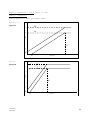
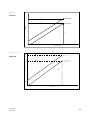
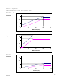
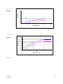
Static forcedeflection corridors are defined for each block of the barrier.
2.1.5.
Dynamic test
2.1.5.1.
The dynamic deformation characteristics, when impacted according to
the protocol described in paragraph 6.
2.1.5.2.
Deviation from the limits of the force-deflection corridors
characterising the rigidity of the impactor - as defined in
appendix 2 - may be allowed provided that:
2.1.5.2.1.
the deviation occurs after the beginning of the impact and before
the deformation of the impactor is equal to 150 mm;
2.1.5.2.2.
the deviation does not exceed 50 per cent
instantaneous prescribed limit of the corridor;
2.1.5.2.3.
each deflection corresponding to each deviation does not exceed
35 mm of deflection, and the sum of these deflections does not
exceed 70 mm (see appendix 2 to this annex);
2.1.5.2.4.
the sum of energy derived from deviating outside the corridor does
not exceed 5 per cent of the gross energy for that block.
2.1.5.3.
Blocks 1 and 3 are identical.
Their rigidity is such that their
force deflection curves fall between corridors of figure 2a.
2.1.5.4.
Blocks 5 and 6 are identical.
Their rigidity is such that their
force deflection curves fall between corridors of figure 2d.
2.1.5.5
The rigidity of block 2 is such that its force deflection curves
fall between corridors of figure 2b.
2.1.5.6.
The rigidity of block 4 is such that its force deflection curves
fall between corridors of figure 2c.
2.1.5.7.
The force-deflection of the impactor as a whole shall fall between
corridors of figure 2e.
2.1.5.8.
The force-deflection curves shall be verified by a test detailed in
annex 5, paragraph 6., consisting of an impact of the barrier
against a dynamometric wall at 35 ± 0.5 km/h.
Version 5.1
June 2011
32
of
the
nearest
2.1.5.9.
The dissipated energy 1/ against blocks 1 and 3 during the test
shall be equal to 9.5 ± 2 kJ for these blocks.
2.1.5.10.
The dissipated energy against blocks 5 and 6 during the test shall
be equal to 3.5 ± 1 kJ for these blocks.
2.1.5.11.
The dissipated energy against block 4 shall be equal to 4 ± 1 kJ.
2.1.5.12.
The dissipated energy against block 2 shall be equal to 15 ± 2 kJ.
2.1.5.13.
The dissipated total energy during the impact shall be equal to
45 ± 3 kJ.
2.1.5.14.
The maximum impactor deformation from the point of first contact,
calculated from integration of the accelerometers according to
paragraph 6.6.3., shall be equal to 330 ± 20 mm.
2.1.5.15.
The final residual static impactor deformation measured after the
dynamic test at level B (figure 2) shall be equal to 310 ± 20 mm.
2.2.
Front plates
2.2.1.
Geometrical characteristics
2.2.1.1.
The front plates are 1,500 ± 1 mm wide and 250 ± 1 mm high.
thickness is 0.5 ± 0.06 mm.
2.2.1.2.
When assembled the overall dimensions of the impactor (defined in
figure 2) shall be: 1,500 ± 2.5 mm wide and 500 ± 2.5 mm high.
2.2.1.3.
The upper edge of the lower front plate and the lower edge of the
upper front plate should be aligned within 4 mm.
2.2.2.
Material characteristics
2.2.2.1.
The front plates are manufactured from aluminium of series AlMg 2 to
AlMg3 with elongation 12 per cent, and a UTS 175 N/mm2.
2.3.
Back plate
2.3.1.
Geometric characteristics
2.3.1.1.
The geometric characteristics shall be according to figures 5 and 6.
2.3.2.
Material characteristics
2.3.2.1.
The back plate shall consist of a 3 mm aluminium sheet.
The back
plate shall be manufactured from aluminium of series AlMg 2 to AlMg3
with a hardness between 50 and 65 HBS.
This plate shall be
perforated with holes for ventilation: the location, the diameter
and pitch are shown in figures 5 and 7.
2.4.
Location of the honeycomb blocks
2.4.1.
The honeycomb blocks shall be centred on the perforated zone of the
The
1/
The amounts of energy indicated are the amounts of energy dissipated by the
system when the extent to which the impactor is crushed is greatest.
Version 5.1
June 2011
33
back plate (figure 5).
2.5.
Bonding
2.5.1.
For both the front and the back plates, a maximum of 0.5 kg/m2 shall
be applied evenly directly over the surface of the front plate,
giving a maximum film thickness of 0.5 mm. The adhesive to be used
throughout should be a two-part polyurethane {such as Ciba Geigy
XB5090/1 resin with XB5304 hardener} or equivalent.
2.5.2.
For the back plate the minimum bonding strength shall be 0.6 MPa,
(87 psi), tested according to paragraph 2.4.3.
2.5.3.
Bonding strength tests:
2.5.3.1.1.
Flatwise tensile testing is used to
adhesives according to ASTM C297-61.
2.5.3.2.
The test piece should be 100 mm x 100 mm, and 15 mm deep, bonded to
a sample of the ventilated back plate material. The honeycomb used
should be representative of that in the impactor, i.e. chemically
etched to an equivalent degree as that near to the back plate in the
barrier but without pre-crushing.
2.6.
Traceability
2.6.1.
Impactors shall carry consecutive serial numbers which are stamped,
etched or otherwise permanently attached, from which the batches for
the individual blocks and the date of manufacture can be established
2.7.
Impactor attachment
2.7.1.
The fitting on the trolley must be according to figure 8.
The
fitting will use six M8 bolts, and nothing shall be larger than the
dimensions of the barrier in front of the wheels of the trolley.
Appropriate spacers must be used between the lower back plate flange
and the trolley face to avoid bowing of the back plate when the
attachment bolts are tightened.
3.
VENTILATION SYSTEM
3.1.
The interface between the trolley and the ventilation system should
be solid, rigid and flat.
The ventilation device is part of the
trolley and not of the impactor as supplied by the manufacturer.
Geometrical characteristics of the ventilation device shall be
according to figure 9.
3.2.
Ventilation device mounting procedure.
3.2.1.
Mount the ventilation device to the front plate of the trolley;
3.2.2.
Ensure that a 0.5 mm thick gauge cannot be inserted between the
ventilation device and the trolley face at any point. If there is a
gap greater than 0.5 mm, the ventilation frame will need to be
replaced or adjusted to fit without a gap of > 0.5 mm.
3.2.3.
Dismount the ventilation device from the front of the trolley;
Version 5.1
June 2011
measure
bond
strength
of
34
3.2.4.
Fix a 1.0 mm thick layer of cork to the front face of the trolley;
3.2.5.
Re-mount the ventilation device to the front of the trolley and
tighten to exclude air gaps.
4.
CONFORMITY OF PRODUCTION
The conformity of production procedures shall comply with those set
out in the Agreement, Appendix 2 (E/ECE/324-E/ECE/TRANS/505/Rev.2),
with the following requirements:
4.1.
The manufacturer shall be responsible for the conformity
production procedures and for that purpose must in particular:
4.1.1.
Ensure the existence of effective procedures so that the quality of
the products can be inspected,
4.1.2.
Have access to the testing
conformity of each product,
4.1.3.
Ensure that the test results are recorded and that the documents
remain available for a time period of 10 years after the tests,
4.1.4.
Demonstrate that the samples tested are a reliable measure of the
performance of the batch (examples of sampling methods according to
batch production are given below).
4.1.5.
Analyse results of tests in order to verify and ensure the stability
of the barrier characteristics, making allowance for variations of
an industrial production, such as temperature, raw materials
quality, time of immersion in chemical, chemical concentration,
neutralisation etc, and the control of the processed material in
order to remove any residue from the processing,
4.1.6.
Ensure that any set of samples or test pieces giving evidence of
non-conformity gives rise to a further sampling and test. All the
necessary steps must be taken to restore conformity of the
corresponding production.
4.2.
The manufacturer's level of certification must be at least ISO 9002
standard.
4.3.
Minimum conditions for the control of production: the holder of an
agreement will ensure the control of conformity following the
methods hereunder described.
4.4.
Examples of sampling according to batch
4.4.1.
If several examples of one block type are constructed from one
original block of aluminium honeycomb and are all treated in the
same treatment bath (parallel production), one of these examples
could be chosen as the sample, provided care is taken to ensure that
the treatment is evenly applied to all blocks. If not, it may be
necessary to select more than one sample.
4.4.2.
If a limited number of similar blocks (say three to twenty) are
treated in the same bath (serial production), then the first and
last block treated in a batch, all of which are constructed from the
Version 5.1
June 2011
equipment
needed
to
inspect
of
the
35
same original block of aluminium honeycomb, should be taken as
representative samples.
If the first sample complies with the
requirements but the last does not, it may be necessary to take
further samples from earlier in the production until a sample that
does comply is found. Only the blocks between these samples should
be considered to be approved.
4.4.3.
Once experience is gained with the consistency of production
control, it may be possible to combine both sampling approaches, so
that more than one groups of parallel production can be considered
to be a batch provided samples from the first and last production
groups comply.
5.
STATIC TESTS
5.1.
One or more samples (according to the batch method) taken from each
batch of processed honeycomb core shall be tested, according to the
following test procedure:
5.2.
The sample size of the aluminium honeycomb for static tests shall be
the size of a normal block of the impactor, that is to say
250 mm x 500 mm x 440 mm for top row and 250 mm x 500 mm x 500 mm
for the bottom row.
5.3.
The samples should be compressed between two parallel loading plates
which are at least 20 mm larger that the block cross section.
5.4.
The compression speed shall be 100 millimetres per minute, with a
tolerance of 5 per cent.
5.5.
The data acquisition for static compression shall be sampled at a
minimum of 5 Hz.
5.6.
The static test shall be continued until the block compression is at
least 300 mm for blocks 4 to 6 and 350 mm for blocks 1 to 3.
6.
DYNAMIC TESTS
For every 100 barrier faces produced, the manufacturer shall make
one dynamic test against a dynamometric wall supported by a fixed
rigid barrier, according to the method described below.
6.1.
Installation
6.1.1.
Testing ground
6.1.1.1.
The test area shall be large enough to accommodate the run-up-track
of the mobile deformable barrier, the rigid barrier and the
technical equipment necessary for the test.
The last part of the
track, for at least 5 metres before the rigid barrier, shall be
horizontal, flat and smooth.
6.1.2.
Fixed rigid barrier and dynamometric wall
6.1.2.1.
The rigid wall shall consist of a block of reinforced concrete not
less than 3 metres wide and not less than 1.5 metres high.
The
thickness of the rigid wall shall be such that it weighs at least
70 tonnes.
Version 5.1
June 2011
36
6.1.2.2.
The front face shall be vertical, perpendicular to the axis of the
run-up-tack and equipped with six load cell plates, each capable of
measuring the total load on the appropriate block of the mobile
deformable barrier impactor at the moment of impact. The load cell
impact plate area centres shall align with those of the six impact
zones of the mobile deformable barrier face.
Their edges shall
clear adjacent areas by 20 mm such that, within the tolerance of
impact alignment of the MDB, the impact zones will not contact the
adjacent impact plate areas. Cell mounting and plate surfaces shall
be in accordance with the requirements set out in the annex to
standard ISO 6487:1987.
6.1.2.3.
Surface
protection,
comprising
a
plywood
face
(thickness:
12 ± 1 mm), is added to each load cell plate such that it shall not
degrade the transducer responses.
6.1.2.4.
The rigid wall shall be either anchored in the ground or placed on
the ground with, if necessary, additional arresting devices to limit
its deflection. A rigid wall (to which the load cells are attached)
having different characteristics but giving results that are at
least equally conclusive may be used.
6.2.
Propulsion of the mobile deformable barrier
At the moment of impact the mobile deformable barrier shall no
longer be subject to the action of any additional steering or
propelling device.
It shall reach the obstacle on a course
perpendicular to the front surface of the dynamometric wall.
Impact alignment shall be accurate to within 10 mm.
6.3.
Measuring instruments
6.3.1.
Speed
The impact speed shall be 35 0.5 km/h the instrument used to
record the speed on impact shall be accurate to within 0.1 percent.
6.3.2.
Loads
Measuring instruments shall meet the specifications set forth in
ISO 6487:1987
CFC
CAC
CAC
CAC
for
for
for
for
all blocks:
blocks 1 and 3:
blocks 4,5 and 6:
block 2:
60
200
100
200
Hz
kN
kN
kN
6.3.3.
Acceleration
6.3.3.1.
The acceleration in the longitudinal direction shall be measured at
three separate positions on the trolley, one centrally and one at
each side, at places not subject to bending.
6.3.3.2.
The central accelerometer shall be located within 500 mm of the
location of the centre of gravity of the MDB and shall lie in a
vertical longitudinal plane which is within ± 10 mm of the centre of
gravity of the MDB.
Version 5.1
June 2011
37
6.3.3.3.
The side accelerometers shall be at the same height as each
other ± 10 mm and at the same distance from the front surface of
the MDB ± 20 mm
6.3.3.4.
The instrumentation shall
following specifications:
comply
with
ISO
6487:1987
with
the
CFC 1,000 Hz (before integration)
CAC 50 g
6.4.
General specifications of barrier
6.4.1.
The individual characteristics of each barrier shall comply with
paragraph 1. of this annex and shall be recorded.
6.5.
General specifications of the impactor
6.5.1.
The suitability of an impactor as regards the dynamic test
requirements shall be confirmed when the outputs from the six load
cell plates each produce signals complying with the requirements
indicated in this annex.
6.5.2.
Impactors shall carry consecutive serial numbers which are stamped,
etched or otherwise permanently attached, from which the batches for
the individual blocks and the date of manufacture can be
established.
6.6.
Data processing procedure
6.6.1.
Raw data: At time T = T0, all offsets should be removed from the
data. The method by which offsets are removed shall be recorded in
the test report.
6.6.2.
Filtering
6.6.2.1.
The raw data will be filtered prior to processing/calculations.
6.6.2.2.
Accelerometer data for integration will be filtered to CFC 180,
ISO 6487:1987.
6.6.2.3.
Accelerometer data for impulse calculations will be filtered to
CFC 60, ISO 6487:1987.
6.6.2.4.
Load cell data will be filtered to CFC 60, ISO 6487:1987.
6.6.3.
Calculation of MDB face deflection
6.6.3.1.
Accelerometer data from all three accelerometers individually (after
filtering at CFC 180), will be integrated twice to obtain deflection
of the barrier deformable element.
6.6.3.2.
The initial conditions for deflection are:
6.6.3.2.1.
velocity = impact velocity (from speed measuring device).
6.6.3.2.2.
deflection = 0
Version 5.1
June 2011
38
6.6.3.3.
The deflection at the left hand side, mid-line and right hand side
of the mobile deformable barrier will be plotted with respect to
time.
6.6.3.4.
The
maximum
deflection
calculated
from
each
of
the
three
accelerometers should be within 10 mm. If it is not the case, then
the outlier should be removed and difference between the deflection
calculated from the remaining two accelerometers checked to ensure
that it is within 10 mm.
6.6.3.5.
If the deflections as measured by the left hand side, right hand
side and mid-line accelerometers are within 10 mm, then the mean
acceleration of the three accelerometers should be used to calculate
the deflection of the barrier face.
6.6.3.6.
If the deflection from only two accelerometers meets the 10 mm
requirement,
then
the
mean
acceleration
from
these
two
accelerometers should be used to calculate the deflection for the
barrier face.
6.6.3.7.
If the deflections calculated from all three accelerometers (left
hand side, right hand side and mid-line) are NOT within the 10 mm
requirement, then the raw data should be reviewed to determine the
causes of such large variation.
In this case the individual test
house will determine which accelerometer data should be used to
determine mobile deformable barrier deflection or whether none of
the accelerometer readings can be used, in which case, the
certification test must be repeated. A full explanation should be
given in the test report.
6.6.3.8.
The mean deflection-time data will be combined with the load cell
wall force-time data to generate the force-deflection result for
each block.
6.6.4.
Calculation of energy
The absorbed energy for each block and for the whole MDB face should
be calculated up to the point of peak deflection of the barrier.
En
t1
t
0
Fn . dsmean
where:
t0
is the time of first contact
t1
is the time where the trolley comes to rest,i.e. where u = 0.
s
is the deflection of the trolley deformable element calculated
according to paragraph 6.6.3.
6.6.5.
Verification of dynamic force data
6.6.5.1.
Compare the total impulse, I, calculated from the integration of the
total force over the period of contact, with the momentum change
over that period (M*V).
6.6.5.2.
Compare the total energy change to the change in kinetic energy of
the MDB, given by:
Version 5.1
June 2011
39
E 1 MV2
K
2
i
where Vi is the impact velocity and M the whole mass of the MDB
If the momentum change (M*V) is not equal to the total impulse
(I) ± 5 per cent, or if the total energy absorbed ( En) is not
equal to the kinetic energy, EK ± 5 per cent, then the test data
must be examined to determine the cause of this error.
Version 5.1
June 2011
40
DESIGN OF IMPACTOR 2/
500 5
250 3
500 5
Zone 5
500 5
Zone 4
Zone 6
Zone 2
Zone 3
500 2.5
250 3
Zone 1
1500 2.5
Figure 1
60 2
Level B
250 3
250 3
500 2 mm
(including the front plate but not the back plate)
Figure 2
____________________
2/
All dimensions are in mm.
The tolerances on the dimensins of the blocks
allow for the difficulties of measuring cut aluminium honeycomb. The tolerance
on the overall dimension of the impactor is less than that for the individual
Version 5.1
June 2011
41
blocks since the honeycomb blocks can be adjusted, with overlap if necessary,
to maintain a more closely defined impact face dimension.
Impactor Top
Direction L
Direction W
Expansion direction of the Aluminium honeycomb
Figure 3 - Aluminium Honeycomb Orientation
19mm ±1.9mm
Figure 4 - Dimension of Aluminium Honeycomb Cells
Version 5.1
June 2011
42
DESIGN OF THE BACK PLATE
1500 + 1mm
520 1mm
≥ 500mm
Figure 5 - Front View
Ventilation
device
Front plate of trolley
514 + 1mm
Cork gasket
Side View
Spacer
≥ 53 mm
Figure 6 - Attachment of backplate to ventillation device and trolley face
plate
Version 5.1
June 2011
43
12 mm 0.2
12 mm 0.2 12 mm 0.2
8 mm 0.2
Figure 7 - Staggered pitch for the back plate ventilation holes
600 + 1mm
150 + 1mm
600 + 1mm
Barrier side
28 + 1mm
≥17 mm
Trolley side
≥ 3 mm
R 5 mm
Top and bottom back plate flanges
Note: The attachment holes in the bottom flange may be opened to slots, as
shown below, for ease of attachment provided sufficient grip can be developed
to avoid detachment during the whole impact test.
150 + 1mm
600 + 1mm
600 + 1mm
Barrier side
28 1mm
R 5mm
Bottom
Version 5.1
June 2011
Trolley side
44
Figure 8
Version 5.1
June 2011
45
VENTILATION FRAME
The ventilation device is a structure made of a plate that is 5 mm thick and
20 mm wide. Only the vertical plates are perforated with nine 8 mm holes in
order to let air circulate horizontally.
1500 2.5 mm
500 2.5 mm
50 mm
between 2
plates
250 mm
250 mm
250 mm
250 mm
250 mm
Thickness: 20 mm
Plates (50*50*4 mm) to fix
the device on trolley by M8
screws.
Front View
5 mm
Section
Lateral view of vertical struts
8 mm
Side View
Figure 9
Version 5.1
June 2011
46
Version 5.1
June 2011
47
Annex 5, Appendices 1 and 2, amend to read:
Annex 5 - Appendix 1
FORCE-DEFLECTION CURVES FOR STATIC TESTS
Blocks 1 & 3
60
Figure 1a
51
50
41
Force (kN)
40
30
20
30
10
4
0
4
0
Block 2
5
10
15
20
Deflection (cm)
25
30
35
40
60
57
Figure 1b
50
46
Force (kN)
40
30
16
20
10
4
0
0
Version 5.1
June 2011
2
5
10
15
20
Deflection (cm)
25
30
35
40
48
Block 4
25
Figure 1c
21
20
17
Force (kN)
15
10
24
5
3
0
0
2
5
10
15
20
25
30
35
Deflection (cm)
Blocks 5 & 6
20
Figure 1d
18
19
16
15,5
14
Force (kN)
12
10
24
8
6
4
3
2
0
0
Version 5.1
June 2011
1
5
10
15
20
25
30
35
Deflection (cm)
49
40
Annex 5 - Appendix 2
FORCE-DEFLECTION CURVES FOR DYNAMIC TESTS
Blocks 1 & 3
Figure 2a
58
Force (kN)
60
43
40
20
30
10
0
3
0
10
20
30
40
30
40
Deflection (cm)
Block 2
70
Figure 2b
60
Force (kN)
50
40
20
16
10
0
3
0
10
20
Deflection (cm)
Block 4
Figure 2c
Force (kN )
60
40
28.5
18.5
20
30
5
5
0
80
10
20
30
40
Deflection (cm)
Version 5.1
June 2011
50
Blocks 5 & 6
Figure 2d
Force (kN)
60
40
25,5
15.5
20
30
05
0
5
8
10
20
30
40
Deflection (cm)
Blocks total
300
Figure 2e
255
Force (kN)
250
205
165
200
150
115
100
30
16
50
0
25
0
3
10
20
30
40
Deflection (cm)
Side View
Version 5.1
June 2011
51