1
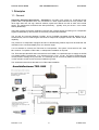
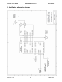
Garrecht Avionik GmbH
TRX-1090 ADS-B Receiver
User Manual
TRX-1090
ADS-B Traffic Receiver
Operation Manual
Installation Manual
© 2011 - Garrecht Avionik GmbH, 55411 Bingen/Germany
Revision: 1.0f
1
31 MAR 2011
Garrecht Avionik GmbH
TRX-1090 ADS-B Receiver
User Manual
Record of Revisions
Always keep this page in front of this document.
Date
Revision Pages Description of Change
Inserted
by
04.08.09
28.08.09
04.12.09
1.0
1.0a
1.0b
All
All
All
JG
JG
JG
07.12.09
07.12.09
24.12.10
31.03.11
1.0c
1.0d
1.0d
1.0f
All
All
All
All
Revision: 1.0f
created
added: Modifications by M. Böhnisch
added: Description of TRX-Tool
added: Schematics
added: Modifications by M. Böhnisch
Modifications by M. Benninger
Inital draft english version
English version released
2
JG
Be
JG
JG
31 MAR 2011
Garrecht Avionik GmbH
TRX-1090 ADS-B Receiver
User Manual
Table of contents
Record of Revisions............................................................................................................................2
Table of contents ................................................................................................................................3
Preface ...............................................................................................................................................4
Unpacking the unit ..............................................................................................................................5
1. Principles ........................................................................................................................................6
1.1. General....................................................................................................................................6
1.2. Output of position data and warnings .......................................................................................8
Position data:..............................................................................................................................8
Warnings: ...................................................................................................................................9
1.2.1. Mode-S Extended Squitter with ADS-B out......................................................................10
1.2.2. Mode-S Squitter..............................................................................................................10
1.2.3. Mode-S Replies ..............................................................................................................10
1.3. Limits of the Systems .............................................................................................................11
1.3.1. General...........................................................................................................................11
1.3.2. The TRX-1090 system provides ......................................................................................11
1.3.3. The TRX-1090 system does NOT provide .......................................................................11
2. Installation.....................................................................................................................................12
2.1. General..................................................................................................................................12
2.2. Mechanical installation ...........................................................................................................12
2.3. Antenna installation................................................................................................................12
2.4. electrical installation (power supply and data interfaces).........................................................13
2.4.1. Antenna connector..........................................................................................................13
2.4.2. USB connector................................................................................................................13
2.4.3. LEDs ..............................................................................................................................13
2.4.4. Data interfaces (Port-1 to Port-4).....................................................................................14
3. PC software TRX-TOOL................................................................................................................17
3.1. Step by Step instruction for successfull installation process....................................................17
3.2. Software and firmware release ...............................................................................................18
3.3. Program and firmware update via internet ..............................................................................18
3.4. Device configuration...............................................................................................................19
4. Check list installation and konfiguration .........................................................................................24
5. Specifications TRX-1090 ...............................................................................................................24
6. Installation schematic diagram ......................................................................................................25
Revision: 1.0f
3
31 MAR 2011
Garrecht Avionik GmbH
TRX-1090 ADS-B Receiver
User Manual
Preface
Many thanks for purchasing the TRX-1090 ADS-B Receiver.
The unit has been developed to include the very popular FLARM collision warning system, which is
installed in more than 13.000 aircraft worldwide. It will be connected between FLARM and external
FLARM compatible display units to simultaneously show FLARM targets and Mode-S transponder
equipped aircraft.
To avoid malfunction, reading and understandinf of all chapters of this manual is required.
A detailed data port specification is described in the “TRX Data Port Specifications” manual, which is
available on request from the manufacuter.
New releases of manuals or firmware udpates are published on the manufacturers website
www.garrecht.com
Your feedback or suggestions for improving the system are welcome. Please contact us via email:
[email protected]
This manual provides all information, that is required for proper installation and safe operation. For
more information, please contact your TRX-1090 dealer. ´
The following symbols and terms are used in this manual:
Warning
Warning statements identify conditions or practices that could result in
injury or loss of life
Caution
Caution statements identify conditions or practices that could result in
damage of this product or other property.
Important note:
Indicates important or usefull information. It is strongly recommended to
read, understand and follow the statement.
Revision: 1.0f
4
31 MAR 2011
Garrecht Avionik GmbH
TRX-1090 ADS-B Receiver
User Manual
Unpacking the unit
The TRX-1090 system is supplied with the following:
•
•
•
•
•
System unit TRX-1090
1:1 Patch cable (shielded) with RJ-45 connectors, length: 0,5m
USB cable
1090 MHz antenna
this manual
If one or more parts are missing, please contact the supplier of the TRX-1090.
Required parts for proper operation
•
•
•
Original FLARM® bzw. licenced 3rd party system (i.e. LX RedBox, ECW100)
External display unit (CDTI), i.e. Butterfly, FlymapL, Garmin GPS 296/495/496, PDA with
appropriate software (i.e. Seeyou mobile, pocket Strepla, WinPilot)
Interconnection cable for external display unit (CDTI)
Options (not delivered with the TRX-1090)
•
•
Antenna line extension
Interconnection cable to GARMIN GPS series 39x/49x or 69x
These options will be supplied by the your TRX-1090 supplier.
Revision: 1.0f
5
31 MAR 2011
Garrecht Avionik GmbH
TRX-1090 ADS-B Receiver
User Manual
1. Principles
1.1. General
Automatic Dependent Surveillance – Broadcast is a modern ATC system for broadcast aircraft
position data. Transponders which are connected to a GPS system transmit her own position and
other flight data, like call sign, Mode-S address, speed and altitude as well as track and vertical
speed. The transponder transmits these data periodically – typically once per second – like a radio
station (Broadcast).
TRX-1090 contains a sensitive 1090 MHz receivers with complex signal processing unit. Transponder
signals broadcasted by other aircraft are received, processed and decoded.
The unit will be connected between FLARM and a FLARM® compatible external display unit, to
simultaneously show FLARM targets and Mode-S transponder equipped aircraft with ADS-B output
capability.
The presence of transponder equipped aircraft not broadcasting ADS-B output will be detected and
indicated on the connected display as a non directed target.
It is not essential to connect the TRX-1090 to a transponder. The system comes with its own 1090
Mhz receiver. To operate a TRX-1090, no transponder installation is required.
The TRX-1090 provides GPS data received from the FLARM via a dedicated port to supply an ADS-B
out capable Mode-S transponder. (e.g. Garrecht Avionic VT-01, VT-02). This device broadcasts the
current position message every secound - the message can be received by ADS-B receivers installed
in other aircraft, as well as with receivers installed on ground.
The schematic below shows the basics of a TRX-1090 installation
Revision: 1.0f
6
31 MAR 2011
Garrecht Avionik GmbH
TRX-1090 ADS-B Receiver
User Manual
System setup and configuration needs to performed using a PC and the TRX-Tool. The unit needs to
be connected to the USB port of your PC. Power will be supplied via the USB port.
Before the first time connection of the TRX-1090 to your PC , the TRXTool needs to be installed properly!
In some cases, the output power of the PC USB port might be insufficient
for powering the TRX-1090 and the system must be powered via an
external power supply.
If connecting the TRX-1090 to your PC, the unit will be set into the On-Ground mode automatically.
The sensitivity will be increased to a maximum value to provide a maximum receiving range (up to
300km, depending on antenna and antenna position).
Signals received from aircraft broadcasting ADS-B messages can be displayed on your PC (virtual
radar).
To prevent a data overflow and jamming the connected displays, the airborne mode provides a
maximum receiving range of 20km.
Revision: 1.0f
7
31 MAR 2011
Garrecht Avionik GmbH
TRX-1090 ADS-B Receiver
User Manual
1.2. Output of position data and warnings
The TRX-1090 provides collision warnings and warnings to prevent dangerour situations
Position data:
The TRX-1090 determins position data of other aircraft and provides position data to connected
displays, if the position is within the configured horizontal and vertical range.
Revision: 1.0f
8
31 MAR 2011
Garrecht Avionik GmbH
TRX-1090 ADS-B Receiver
User Manual
Warnings:
The TRX-1090 warnings focus on different situations:
1. Entering the protection volume
The protection volume is defined as a cylindric volume around the own position. Radius and height of
the Cylinder can be configured using the TRX-Tool. A warning will be generated if an aircraft violates
the defined protection volume (if falling below the vertical AND horizontal limits)
2. Prediction of crossing the flight tracks
Derived from the own position and trajectory data (position, speed, flight direction, vertical speed) and
data from other aircraft, the TRX-1090 calculates the risk of a collision. If detecting a dangerous
situation, a warning will be generated 18 sec. before collision.
WARNING: Due to sudden changes of the own or other aircraft’s flight
direction (track), this warning can be generated later / only few secounds
before a calculated collision.
Revision: 1.0f
9
31 MAR 2011
Garrecht Avionik GmbH
TRX-1090 ADS-B Receiver
User Manual
1.2.1. Transponder signals and system reaction
Different transponder signals (ADS-B, Mode-S Replies, Mode-S Squitters) result in different system
reaction. The table below shows the different signals and the related reactions.
1.2.1. Mode-S Extended Squitter with ADS-B out
Broadcasted by
Mode-S Transponder equipped aircraft WITH connected GPS
Broadcast interval
System reactions
TRX-1090
1 /sek.
Output of aircraft’s position and altitude data via system interfaces according to
interface configuration.
Output of warnings (violating the protection volume, collision warning)
A warning is always focussing the most dangerous aircraft.
FLARM® Warnings have always higher priority. If an aircraft is equipped with
FLARM® and ADS-B out, only FLARM® warnings will be processed.
1.2.2. Mode-S Squitter
Broadcasted by
Mode-S Transponder equipped aircraft WITHOUT connected GPS
Broadcast interval
System
reactions
TRX-1090
1 /sek.
Detecting of horizontal approximation (analyzing the signal strength).
Alitude information will not be processed.
1.2.3. Mode-S Replies
Broadcasted by
Mode-S Transponder equipped aircraft, which are interrogated by radar
ground station or TCAS
Broadcast interval
System
reactions
TRX-1090
Depending on external interrogation, every 4-6 sek.
Detecting of horizontal approximation (analyzing the signal strength)
Detecting of vertical approximation (processing the coded altitude signals)
Revision: 1.0f
10
31 MAR 2011
Garrecht Avionik GmbH
TRX-1090 ADS-B Receiver
User Manual
1.3. Limits of the Systems
1.3.1. General
The system has been developed as a support for VFR pilots. It is not
certified as a TCAS system. The data port does not provide valid data
for certified hazard displays.
Observing the airspace is always under responsibility of the pilot in command. The TRX-1090
acts as a support device, which may operate wrong and generate wrong warnings or no
warnings in dangerour situations.
Using the TRX-1090 and interpreting the warning generated by the device is under the sole
responsibility of the pilot in command.
Displaying traffic information and providing collision avoidance information on connected 3rd
party displays is under the sole responsibilty of the display manufacturer. It can not be
influenced by Garrecht Avionik GmbH.
Garrecht Avionik GmbH assumes no liability for any direct or indirect damage to human and material
arising from the use of the TRX-1090, unless grossly negligent or intentional acts of Garrecht Avionik
GmbH is demonstrated.
If traffic information or collision avoidance should be provided by the TRX-1090, the system must
know it’s position and pressure altitude information. Thus an external operating FLARM® must be
present and connected.
1.3.2. The TRX-1090 system provides
•
Position determination and visualisation of ADS-B 1090 ES out and / or FLARM® equipped aircraft.
•
Generation of directed warnings of ADS-B 1090 ES out Funktion and / or FLARM® equipped aircraft, if
the configured distances (protection volume) is violated or risk of collision occurs.
•
Generation of undirected warnings of Mode-S equipped aircraft without ADS-B 1090 ES out capability.
Approximation of such aircraft is determined by analysing the field strength.
•
Providing of FLARM® and ADS-B 1090 ES out warnings and aircraft position on two external ports for
connection of appropriate 3rd party display systems.
1.3.3. The TRX-1090 system does NOT provide
•
Mode-S SSR transponder capability. The TRX-1090 is NO transponder!!!
•
Active interrogation of other SSR transponders (TRX-1090 is NO TCAS)
•
Resolution advisory similar to TCAS
•
Position determination or directed warnings of Mode-A/C and Mode-S (no ADS-B out) equipped aircraft
•
Generation of traffic information or collision avoidance warning, if no internal FLARM® is present and no
external FLARM® is connected.
Revision: 1.0f
11
31 MAR 2011
Garrecht Avionik GmbH
TRX-1090 ADS-B Receiver
User Manual
2. Installation
2.1. General
The installation has to be carried out following the instructions of this manual by a qualified person in
accordance with the appropriate standards. Please concact a qualified person or aircraft maintenance
organisation, if required tools or specific skills are not available.
Be sure, that the installed TRX-1090 does not reduce the performance of other instruments.
The TRX-1090 has been developed to include the popular FLARM system. An installed and operating
original FLARM or 3rd party licenced product (i.e. LX Red Box) is required for a proper installation. The
FLARM provides the GPS data, which are essential for the operation of the TRX-1090.
Received data and warnings will be provided optically and audible via external FLARM compatible
displays (z.B. Butterfly, FlymapL o.ä.) or PDA with appropriate software or GPS with TIS interface.
According to EASA Decision 2006/13/R and 2006/14/R the TRX-1090 is a standard part. The
installation in CS-22 aircraft (gliders and powered gliders) does not require additional approval or
paperwork.
Operating the TRX-1090 does not require an on board
installed transponder
The TRX-1090 provides interfacing via four RJ-45 connectors. To prevent interference with the radio,
it is strongly recommended to use shielded cables.
2.2. Mechanical installation
The powder coated aluminum housing provides 4 mounting holes (see sketch in the appendix for
dimensions). Install the TRX-1090 on a plane surface without bending the unit
The housing is not water proof. Please choose an appropriate place for installation.
After water contact, the unit may not be powered to prevent internal damage. Please send the unit to
your dealer for maintenance in this case.
2.3. Antenna installation
The stub antenne provided with the TRX-1090 needs to be installed in manner not to be covered by
conductive or shielding material (metal, carbon fibre). If required, use an antenna line extension for
remote antenna installation.
For external antenna installation, a standard transponder antenna can used. The
installation position needs to be choosen carefully. The antenna needs a free line
of sight in horizontal direction. Metal parts (engine, prop, undercarriage) close to
the antenna may influence the performance of the antenna.
Minimum distance to radio antenna is 1m, to transponder and/or DME antenna is
2m.
A stub antenna or fin antenna requires the installation of a ground plane. In
composite airframes, the ground plane should be made of a conductive sheet of metal (size
30x30cm). Install the antenna in the center of this ground plane. Wrong dimensions of the ground
plane of bad contact between antenna foot and ground plane and antenna line ground may reduce the
performance of the antenna. Always remove isolating coatings between antenna and ground plane.
Revision: 1.0f
12
31 MAR 2011
Garrecht Avionik GmbH
TRX-1090 ADS-B Receiver
User Manual
If a Mode-S transponder is installed in the aircraft, it is required to set up your FLARM with the same
Mode-S address (see FLARM instructions and FLARM Tool for further details) to prevent confusing
caused by double targeting.
2.4. electrical installation (power supply and data interfaces)
The unit provides an USB interface and an SMA antenna connector on the front side. Two LEDs
indicate the system status.
Antenna
conncetor
USB-Interfacd
LED 1
LED 2
2.4.1. Antenna connector
Connect the receiving antenna to the antenna connector. If required, use an appropriate antenna line
extensions for remote antenna installation.
Fasten the antenna nut by hand only to prevent damaging the antenna connector (not covered by
manufacturer’s warranty).
2.4.2. USB connector
The USB interface is intended to be used to connect the TRX-1090 to your PC for configuration
purposes.
Before the first time connection of the TRX-1090 to your PC , the TRXTool needs to be installed properly!
In some cases, the output power of the PC USB port might be insufficient
for powering the TRX-1090 and the system must be powered via an
external power supply
If connecting the TRX-1090 to your PC, the unit will be set into the On-Ground mode automatically.
The sensitivity will be increases to a maximum value to provide a maximum receiving range (up to
300km, depending on antenna and antenna position) to use the unit as a on ground ADS-B receiver
for real time flight tracking.
2.4.3. LEDs
Two LEDs indicate the status of the TRX-1090:
LED 1:
on
:
Flashing periodically:
Flashing short: -
USB connection established successfully
-
LED 2:
on
:
blinkt regelmäßig:
Flashing short:
Sending and receivind data via USB
-
Revision: 1.0f
13
31 MAR 2011
Garrecht Avionik GmbH
TRX-1090 ADS-B Receiver
User Manual
2.4.4. Data interfaces (Port-1 to Port-4)
4 interface connectors are located on the backside of the TRX-1090. Each port can be configured
seperatly using the TRX-Tool.
If using standard patchkabel, be sure to use 1:1 cable.
DO NOT US crossover cable to prevent injury of FLARM, TRX-1090
or connected display units.
View TRX-1090 backside
2.4.4.1. Use of interface ports
Port -#
1
2
3
4
Funktion
Power supply, NMEA output for supplying Mode-S transponders
CDTI 1, Interface 1 for vockpitdisplay (kompatibel zu FLARM extended Displays )
CDTI 2, Schnittstelle 2 zu Cockpitdisplay (compatibel zu FLARM basic Display oder
GARMIN GPS series 39x, 49x, 69x), configuration via TRX-Tool
FLARM® I/O, interface to FLARM®
•
External power can be supplied using each of the 4 ports. Using a fuse is required to prevent
damages. Missing fuse or wrong fuse dimension can cause damages, which are not covered
by manufacturers warranty.
•
Do not feed electrical power through the 3.3V pins of the CDTI interfaces (port 2 and port 3) to
prevent damaging internal circuits of the TRX-1090.
•
Max. outout current of the internal 3.3V converter: 0,5 A
•
The use of 6 pin connectors (RJ-12) is possible in an 8 pin RJ-45 connector, but connector
lifetime will be reduced. So the use of 8 pin RJ-45 connectors is strongly recommended.
•
If connecting a GARMIN GPS series 39x, 49x, 69x, the TIS interface needs to be activated
(consult the user manual of the GARMIN GPS).
Revision: 1.0f
14
31 MAR 2011
Garrecht Avionik GmbH
TRX-1090 ADS-B Receiver
User Manual
2.4.4.2. Pinout of the RJ-45 connectors
The pinout complies with the standards of the International Gliding
Commission (IGC) for flight recoders. The pin numbering is reversed to the
industrial standard.
Remind, that the TX/RX lines of port 2 and port 3 (CDTI interfaces) are reversed to the IGC standard.
Pin 3 provides a 3.3V DC power supply for powering external FLARM displays. This makes the
interface compatible to existing external FLARM compatible displays.
Power can be supplied via each port. Be sure to power only FLARM and TRX-1090 via this lines to
prevent exceeding the maximum current.
Pin out RJ-45 connector
Pin #
1
2
3
4
5
6
7
8
Pin out Port 1
Function
+ 9 - +28 V DC
+ 9 - +28 V DC
n.c. (not connected)
n.c. (not connected)
RX 1 (Data input 1)
TX 1 (Data output 1)
GND
GND
It is recommended to power the TRX-1090 via port 1. Use the NMEA data provided on port 1 to feed
your Mode-S transponder for ADS-B out purposes. The baudrate can be set up using the TRX-Tool.
Pin #
1
2
3
4
5
6
7
8
Revision: 1.0f
Pin out Port 4
Funktion
+ 9 - +28 V DC
+ 9 - +28 V DC
n.c. (not connected)
n.c. (not connected)
RX 4
TX 4
GND
GND
15
31 MAR 2011
Garrecht Avionik GmbH
TRX-1090 ADS-B Receiver
User Manual
Connect your FLARM to port 4 to establish connection to power supply and interfaces. Use a 1:1 RJ45 patchcable (delivered with the TRX-1090)
Pin out port 2 and port 3 (CDTI 1, CDTI 2)
Pin #
1
2
3
4
5
6
7
8
Pin out port 2 and Port 3
Funktion
+ 9 - +28 V DC
+ 9 - +28 V DC
3,3V Supply for external displays
GND
TX 2 / TX 3
RX 2 / RX 3
GND
GND
Connect existing CDTI to port 2 or port 3. 3.3V DC power will be supplied by the TRX-1090
Default settings port 2 and port 3:
Port 2:
preconfigured for connecting external FLARM extended displays (Butterfly, FlymapL,
PDA with appropriate software
Port 3:
preconfigured for connecting FLARM® Basic Displays (V2, V3, V4)
Default settings might be changed using the TRX-Tool.
Future firmware upgrades will make the TRX-1090 compatible to other display systems.
The TRX-Tool software checks periodically for new updates. Sending the unit to your dealer for
firmware upgrades is not required.
New information about firmware will be published on the manufacturers website.
www.garrecht.com
Revision: 1.0f
16
31 MAR 2011
Garrecht Avionik GmbH
TRX-1090 ADS-B Receiver
User Manual
3. PC software TRX-TOOL
Configuring the system interfaces requires using the TRX-TOOL PC software. Die Konfiguration der
Geräteschnittstellen erfolgt über das Programm TRX-TOOL. . A PC with Windows XP or newer is
required to run the software. The TRX-1090 will be powered via USB during the configuration process.
In some cases, the output power of the PC USB port might be insufficient for powering the
TRX-1090 and the system must be powered via an external power supply
The newest release of the TRX-Tool is available free of charge on the manufacturer’s website.
www.garrecht.com
3.1. Step by Step instruction for successfull installation process
1. Do not connect the TRX-1090 to your PC
2. Download the TRX-TOOL installer from the manufacturer’s website and store it on your
computer
3. Start the installation by double clicking the downloaded file.
4. Follow the instructions of the installer
5. Connect the TRX-1090 to the USB port of your PC to complete the USB / FTDI driver
installation and follow the instructions shown in the dialogs
6. Start the software after successfull installation to check for updates (internet connection
required)
7. Updates will be installed, if available
8. After the update process, the software needs to be restarted.
9. A connection will be established now. TRX-Tool show the status of the connection
10. If an older firmware will be detected, the TRX-Tool offers to update the TRX-1090 by a newer
version.
11. TRX-Tool is ready for use now.
Revision: 1.0f
17
31 MAR 2011
Garrecht Avionik GmbH
TRX-1090 ADS-B Receiver
User Manual
TRX-Tool main window (no TRX connected)
3.2. Software and firmware release
The title bar of the TRX-TOOL shows software release of the TRX-Tool (1.11) and integrated firmware
release for the connected TRX device (020).
3.3. Program and firmware update via internet
The TRX-TOOL checks the web automatically for newer release. This process can be invoked
manually vie File.Check web for software updates.
Revision: 1.0f
18
31 MAR 2011
Garrecht Avionik GmbH
TRX-1090 ADS-B Receiver
User Manual
3.4. Device configuration
TRX-Tool main window (TRX device connected)
Type: Detected TRX device
Firmware: Reports firmware release of connected TRX device
Status: Reports the connection status
Discard changes
Reloads stored configuration data from connected TRX device.
Settings made in the TRX-TOOL will be overwritten without further
notification.
Save settings
Transfers current configuration data made in the TRX-TOOL to the
TRX device.
Default settings
Resets all user configuration in the TRX-TOOL to factory setting.
Transfering the default data to the TRX device must be triggered by
clicking Save Settings.
Traffic Viewer
Starts a basic traffic viewer to show live ADS-B and FLARM® traffic
Revision: 1.0f
19
31 MAR 2011
Garrecht Avionik GmbH
TRX-1090 ADS-B Receiver
User Manual
ICAO Mode-S Adresse
Enter your own 24 Bit ICAO
Mode-S adress to suppress
warnings from own
transponder
Protection volume
If falling below BOTH values,
a warning will be generated to
indicate dangerous situation in
case of change the flight
direction.
Warning detection band
Aircraft within this altitude
band are considered in the
collision avoidance algorithms.
Traffic warning
ADS-B
Activates warnings of ADS-B
out equipped aircraft (this
feature can not be disabled)
Mode-S
Activates warnings of Mode-S
equipped aircraft
Configuration Port 1
This port is preconfigured as a
NMEA output (i.e. for
supplying Mode-S
transponders with GPS data)
Baudrate
Sets up the baudrate for the
NMEA data stream.
Consult the manual of the
connected device for proper
settings.
Revision: 1.0f
20
31 MAR 2011
Garrecht Avionik GmbH
TRX-1090 ADS-B Receiver
User Manual
Configuration Port 2
This port can be configured for
connecting FLARM basic
(LED) displays or Flarm
extended devices (such as
Butterfly).
Connected equipment:
Preconfigures setttings
depending on the choosen
display type. Depending on
the used display or your
preferences, manuell
modification of the settings
might be required.
Hor. + vert. Range
Sets the maximum display
range for indicating aircraft
position
Baudrate
Sets up the baudrate for the
data stream (consult the
display manual for proper
setting)
Display non-ADSB traffic
No
No warnings of aircraft without
ADS-B out will be send from
the TRX device.
As circling LED
Warnings of aircraft without
ADS-B out will be indicated as
rotating Bearing position /
LED.
With empty bearing field
Warnings of aircraft without
ADS-B out are interpreted
from the connected display in
an own manner. Please check
the display manual for detailed
information.
GPS data
Activates GPS data set in the
data stream (requried for
Flarm extended displays)
Revision: 1.0f
21
31 MAR 2011
Garrecht Avionik GmbH
TRX-1090 ADS-B Receiver
User Manual
Configuration Port 3
This port can be used for
connecting Flarm basic or
extended displays (see port-2 )
as well as for connecting
display devices with GARMIN
TIS compatible interface
Anschlußnutzung
Konfiguration des gewünschten
Display-Typs
Anzeigebereich
Refer to port 2
For Garmin TIS protocoll:
Vertical range can be
configured
Baudrate
Refer to port 2
Nicht-ADSB
Verkehrswarnungen
Nein
Refer to port 2
Als umlaufende LED
Refer to port 2
Mit leerem Bearing Datenfeld
Refer to port 2
Displaytyp GARMIN
As circling balls
Rotating string of pearls around
the own position
Revision: 1.0f
22
31 MAR 2011
Garrecht Avionik GmbH
TRX-1090 ADS-B Receiver
User Manual
Configuration Port 4
This port is configured as
FLARM I/O port. No change
of settings are possible.
Note:
A TRX device configures a
connected external FLARM®
device to a 38.400 bps.
For restoring to factory
settings. press the Button on
the frontpanel of the external
FLARM® device at least for
20 secs.
Revision: 1.0f
23
31 MAR 2011
Garrecht Avionik GmbH
TRX-1090 ADS-B Receiver
User Manual
4. Check list installation and konfiguration
Check all items of the checklist shown below in order to verify your
installation.
TRX-1090 manual read and unterstood completely.
TRX-1090 configured (i.e. protection volume, port configuration)
24 Bit Mode-S aircraft adress entered in the TRX-1090 aircraft (only required, if the aircraft is
Mode-S equipped)
Device installed in suitable position.
Connection to external displays established and tested
All antennas installed in accordance with the instructions of the manual and connected to the
device
Shortbreaker installed
All cables placed in right position. Cables overlengths tied in 8-shape loops, not in ring loops.
Final test of complete system
Emergency canopy release tested. and not impaired by installation
5. Specifications TRX-1090
Dimensions
115 x 73 x 27.5mm (LxWxH)
Mass
0.18 kg
Supply Voltage
9 - 16 V DC
Output voltage for external displays
3.3 V, max. 0.5A
Current consumption
Appr.. 80mA @ 12V DC
Required circuit breaker
500 mA (slow blow) or 1A w. Flarm
Interfaces
4x RS-232
1x USB
Operating frequencies
1090 MHz
Temperatures
Revision: 1.0f
Operating
-20°C - +70°C
Storage
-30°C - +80°C
24
31 MAR 2011
Garrecht Avionik GmbH
TRX-1090 ADS-B Receiver
User Manual
6. Installation schematic diagram
Revision: 1.0f
25
31 MAR 2011
Garrecht Avionik GmbH
TRX-1090 ADS-B Receiver
User Manual
6.1. Dimensions
Revision: 1.0f
26
31 MAR 2011