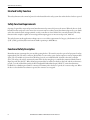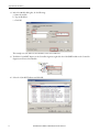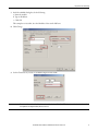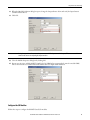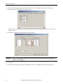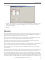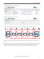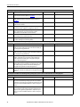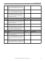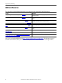
1
Application Technique
Safety Function: Door Monitoring
Products: Trojan 5 Switch, GuardLogix Controller
Safety Rating: CAT. 3, PLd to ISO 13849-1: 2008
Topic
Page
Important User Information
2
General Safety Information
3
Introduction
3
Safety Function Realization: Risk Assessment
3
Interlock Safety Function
4
Safety Function Requirements
4
Functional Safety Description
4
Bill of Material
5
Setup and Wiring
5
Configuration
6
Programming
13
Calculation of the Performance Level
14
Verification and Validation Plan
17
Additional Resources
20
Safety Function: Door Monitoring
Important User Information
Read this document and the documents listed in the additional resources section about installation, configuration, and
operation of this equipment before you install, configure, operate, or maintain this product. Users are required to
familiarize themselves with installation and wiring instructions in addition to requirements of all applicable codes, laws,
and standards.
Activities including installation, adjustments, putting into service, use, assembly, disassembly, and maintenance are required
to be carried out by suitably trained personnel in accordance with applicable code of practice.
If this equipment is used in a manner not specified by the manufacturer, the protection provided by the equipment may be
impaired.
In no event will Rockwell Automation, Inc. be responsible or liable for indirect or consequential damages resulting from the
use or application of this equipment.
The examples and diagrams in this manual are included solely for illustrative purposes. Because of the many variables and
requirements associated with any particular installation, Rockwell Automation, Inc. cannot assume responsibility or
liability for actual use based on the examples and diagrams.
No patent liability is assumed by Rockwell Automation, Inc. with respect to use of information, circuits, equipment, or
software described in this manual.
Reproduction of the contents of this manual, in whole or in part, without written permission of Rockwell Automation,
Inc., is prohibited.
Throughout this manual, when necessary, we use notes to make you aware of safety considerations.
WARNING: Identifies information about practices or circumstances that can cause an explosion in a hazardous environment,
which may lead to personal injury or death, property damage, or economic loss.
ATTENTION: Identifies information about practices or circumstances that can lead to personal injury or death, property
damage, or economic loss. Attentions help you identify a hazard, avoid a hazard, and recognize the consequence.
IMPORTANT
Identifies information that is critical for successful application and understanding of the product.
Labels may also be on or inside the equipment to provide specific precautions.
SHOCK HAZARD: Labels may be on or inside the equipment, for example, a drive or motor, to alert people that dangerous
voltage may be present.
BURN HAZARD: Labels may be on or inside the equipment, for example, a drive or motor, to alert people that surfaces may
reach dangerous temperatures.
ARC FLASH HAZARD: Labels may be on or inside the equipment, for example, a motor control center, to alert people to
potential Arc Flash. Arc Flash will cause severe injury or death. Wear proper Personal Protective Equipment (PPE). Follow ALL
Regulatory requirements for safe work practices and for Personal Protective Equipment (PPE).
2
Rockwell Automation Publication SAFETY-AT060C-EN-P - December 2014
Safety Function: Door Monitoring
General Safety Information
Contact Rockwell Automation to find out more about our safety risk assessment services.
IMPORTANT
This application example is for advanced users and assumes that you are trained and experienced in safety system requirements.
ATTENTION: Perform a risk assessment to make sure all task and hazard combinations have been identified and addressed. The risk
assessment can require additional circuitry to reduce the risk to a tolerable level. Safety circuits must take into consideration safety
distance calculations, which are not part of the scope of this document.
Introduction
This safety function application technique explains how to wire, configure, and program a Compact GuardLogix®
controller and POINT Guard I/O™ module to monitor a Trojan™ 5 tongue interlock switch that is mounted on a door. If
the door is opened, or a fault is detected in the monitoring circuit, the GuardLogix® controller de-energizes the final control
device, in this case, a redundant pair of 100S-C contactors.
This example uses a Compact GuardLogix controller, but is applicable to any GuardLogix controller. This example uses a
Trojan 5 tongue switch, but is applicable to dual, dry-contact devices with at least two N.C. contacts. The SISTEMA
calculations shown later in this document would have to be re-calculated using the actual products.
Safety Function Realization: Risk Assessment
The required performance level is the result of a risk assessment and refers to the amount of the risk reduction to be carried
out by the safety-related parts of the control system. Part of the risk reduction process is to determine the safety functions of
the machine. In this application, the performance level required (PLr) by the risk assessment is Category 3, Performance
Level d (CAT. 3, PLd), for each safety function. A safety system that achieves CAT. 3, PLd, or higher, can be considered
control reliable. Each safety product has its own rating and can be combined to create a safety function that meets or
exceeds the PLr.
From: Risk Assessment (ISO 12100)
1. Identification of safety functions
2. Specification of characteristics of each function
3. Determination of required PL (PLr) for each safety function
To: Realization and PL Evaluation
Rockwell Automation Publication SAFETY-AT060C-EN-P - December 2014
3
Safety Function: Door Monitoring
Interlock Safety Function
This safety function is the removal of power from the hazard when the safety system detects that the door has been opened.
Safety Function Requirements
Opening of a guard door stops and prevents hazardous motion by removal of power to the motor. When the door is closed,
hazardous motion and power to the motor does not resume until a secondary action (Start button depressed) occurs. Faults
at the door interlock switch, wiring terminals, or safety controller are detected before the next safety demand. The safety
function in this example is capable of connecting and interrupting power to motors rated up to 9A, 600V AC.
The safety function in this application technique meets or exceeds the requirements for Category 3, Performance Level d
(CAT. 3, PLd), per ISO 13849-1 and control reliable operation per ANSI B11.19.
Functional Safety Description
Hazardous motion is interrupted or prevented by opening the door. The switch is wired to a pair of safety inputs of a safety
input module (SI1). The safety contactors (K1 and K2) are connected to a pair of safety outputs on a safety output module
(SO1). The I/O module is connected via CIP Safety protocol over an EtherNet/IP™ network to the safety controller
(SC1). The safety code in SC1 monitors the status of the door by using the pre-certified safety instruction Dual Channel
Input Stop with Test (DCST). When all safety input interlocks are satisfied, no faults are detected, and the reset button is
pressed, a second certified function block called Configurable Redundant Output (CROUT) controls and monitors
feedback for a redundant pair of 100S-C contactors. In summary, when the door is opened, the contactors drop out. When
the door is closed and the Reset button is pressed, the contactors are energized.
4
Rockwell Automation Publication SAFETY-AT060C-EN-P - December 2014
Safety Function: Door Monitoring
Bill of Material
This application uses these products.
Cat. No.
Description
Quantity
440K-T11090
Trojan 5 standard safety interlock switch
1
800FM-G611MX10
800F Reset button - metal, guarded, blue, R, metal latch mount, 1 N.O. contact, standard
1
100S-C09ZJ23C
Bulletin 100S-C - safety contactors
2
1768-ENBT
CompactLogix™ EtherNet/IP bridge
1
1768-L43S
Compact GuardLogix processor, 2.0 MB standard memory, 0.5 MB safety memory
1
1768-PA3
Power supply, 120/240 V AC input, 3.5 A @ 24V DC
1
1769-ECR
Right end cap/terminator
1
1734-AENT
24V DC Ethernet adapter
1
1734-TB
Module base with removable IEC screw terminals
4
1734-IB8S
POINT Guard I/O safety input module
1
1734-OB8S
POINT Guard I/O safety output module
1
1783-US05T
Stratix 2000™ unmanaged Ethernet switch
1
Setup and Wiring
For detailed information on installing and wiring, refer to the publications listed in the Additional Resources on the back
cover.
System Overview
The POINT Guard I/O 1734-IB8S input module monitors the two channels of the Trojan 5 switch. If the door is opened,
these two channels open, and the controller reacts by dropping out the safety contactors.
The POINT Guard I/O 1734-IB8S module can source the 24V DC for both channels to dynamically test the signal wiring
for shorts to 24V DC and channel-to-channel shorts. If a fault occurs, either or both channels are set to 0 (low), and the
controller reacts by dropping out the safety contactors. Only after the fault is cleared and the door is cycled, does the
function block reset.
Shorts to 0V DC (and wire off ) are seen as an open circuit by the POINT Guard I/O 1734-IB8S input module and the
controller reacts by dropping out the safety contactors. If the inputs remain discrepant for longer than the discrepancy time,
then the function block Dual Channel Input Stop with Test (DCST) in the controller declares a fault. Only after the fault
is cleared and the door is cycled, does the function block reset.
The final control device in this case is a pair of 100S-C safety contactors, K1 and K2. The contactors are controlled by a
POINT Guard I/O 1734-OB8S safety output module. The contactors are wired in a redundant series configuration. A
feedback circuit is wired through the N.C. auxiliary contact and back to an input on the POINT Guard I/O 1734-IB8S
module to monitor the contactors for proper operation. The contactors cannot restart if the feedback circuit is not in the
correct state.
Rockwell Automation Publication SAFETY-AT060C-EN-P - December 2014
5
Safety Function: Door Monitoring
The system has individual reset buttons for resetting of faults and safety outputs.
The reset buttons and the contactor feedback circuit are all wired to the POINT Guard I/O 1734-IB8S module in this
example. This is not required for functional safety. These three inputs could be wired to a standard input module.
Electrical Schematic
24V DC
Safety Reset
11
12
21
22
Fault Reset
10
11
14
15
12
13
16
17
COM
COM
COM
COM
T0
T1
T2
T3M
33
34
1734-IB8S
24V DC Common
00
01
04
05
02
03
06
07
COM
COM
COM
COM
COM
COM
COM
COM
1734-OB8S
Configuration
The Compact GuardLogix controller is configured by using RSLogix™ 5000 software, version 17 or later. You must create a
new project and add the I/O modules. Then, configure the I/O modules for the correct input and output types. A detailed
description of each step is beyond the scope of this document. Knowledge of the RSLogix 5000 programming environment
is assumed.
Configure the Controller and Add I/O Modules
Follow these steps to configure the controller and to add I/O modules.
6
Rockwell Automation Publication SAFETY-AT060C-EN-P - December 2014
Safety Function: Door Monitoring
1. In RSLogix 5000 software, create a new project.
2. In the Controller Organizer, add the 1768-ENBT module to the 1768 Bus.
3. Select the 1768-ENBT module and click OK.
Rockwell Automation Publication SAFETY-AT060C-EN-P - December 2014
7
Safety Function: Door Monitoring
4. In the New Module dialog box, do the following:
a. Name the module.
b. Type its IP address.
c. Click OK.
This example uses 192.168.1.8 as the IP address. Yours can be different.
5. To add the 1734-AENT adapter, in the Controller Organizer, right-click the 1768-ENBT module in the Controller
Organizer and choose New Module.
6. Select the 1734-AENT adapter and click OK.
8
Rockwell Automation Publication SAFETY-AT060C-EN-P - December 2014
Safety Function: Door Monitoring
7. In the New Module dialog box, do the following:
a. Name the module.
b. Type its IP address.
c. Click OK
This example uses 192.168.1.11 as the IP address. Yours can be different.
8. Click Change.
9. Set the Chassis Size at 3 for the 1734-AENT adapter and click OK.
IMPORTANT
Chassis size is the number of modules that are inserted in the chassis. The 1734-AENT adapter is considered to be in slot 0, so for
one input and one output module, the chassis size is 3.
Rockwell Automation Publication SAFETY-AT060C-EN-P - December 2014
9
Safety Function: Door Monitoring
10. In the Controller Organizer, right-click the 1734-AENT adapter and choose New Module.
11. In the Select Module dialog box, do the following:
a. Expand Safety.
b. Select the 1734-IB8S module.
c. Click OK.
12. In the New Module dialog box, name the device 'IB8S'and click Change.
10
Rockwell Automation Publication SAFETY-AT060C-EN-P - December 2014
Safety Function: Door Monitoring
13. When the Module Definition dialog box opens, change the Output Data to None and verify the Input Status is
Combined Status-Power.
14. Click OK.
IMPORTANT
Setting the output data to None means that you cannot use the Test Outputs as standard outputs. This saves one controller
connection because we are only using the input connection.
15. Close the Module Properties dialog box by clicking OK.
16. Repeat steps 10…15 to add the POINT Guard I/O 1734-OB8S safety output module, name the module OB8S,
choose slot 2 and choose Combined Status-Readback-Power for Input Status definition.
Configure the I/O Modules
Follow these steps to configure the POINT Guard I/O modules.
Rockwell Automation Publication SAFETY-AT060C-EN-P - December 2014
11
Safety Function: Door Monitoring
1. In the Controller Organizer, right-click the POINT Guard I/O 1734-IB8S module and choose Properties.
2. Click Test Output and configure the module as shown.
T0 and T1 are being used to pulse test the Trojan 5 switch channels. T2 is being used to pulse test the contactor
feedback circuit.
3. Click Input Configuration and configure the module as shown.
IMPORTANT
Inputs 0/1 are the Light Curtain. Inputs 4/5 are the reset buttons. Input 7 is contactor monitoring circuit. Recall that input 7 is
being sourced from Test Output 2.
4. Click OK.
5. In the Controller Organizer, right-click the POINT Guard I/O 1734-OB8S module and choose Properties.
12
Rockwell Automation Publication SAFETY-AT060C-EN-P - December 2014
Safety Function: Door Monitoring
6. Click Output Configuration and configure the module as shown.
Typically, contactor coils will not react to the pulse testing of the output wires. If using a contactor that does react to
the pulse test, then disable the pulse testing. This should not affect the overall safety rating if redundancy and
monitoring are being utilized.
7. Click OK.
Programming
The Dual Channel Input Stop with Test (DCST) instruction monitors dual-input safety devices whose main function is to
stop a machine safely, for example, a safety gate. When a test function is requested, programmatically or manually, the
operation of the machine is halted until a proper cycle of the safety gate occurs.
The DCST instruction monitors dual-input channels for consistency (Equivalent - Active High) and detects and traps
faults when the inconsistency is detected for longer than the configured Discrepancy Time (ms).
The automatic restart type allows the DCST output (O1) to reset automatically after a demand. The manual action
typically required for safety is provided in rung 1 to reset the safety output enable.
Input Status typically represents the channel status of the two input channels. In this example, the Combined Input Status
bit goes to 0 (low) if any of the 8 input channels on the POINT Guard I/O 1734-IB8S module have a fault.
In this example, the DCST reset acts as a fault reset. Even when configured for automatic restart, a reset is required to
recover from a fault.
The output (O1) of the DCST instruction is used as a safety interlock in the seal-in rung to drive the output enable tag. If
the DCS output drops out, so does the output enable, and it remains OFF until a manual reset action is carried out.
The Configurable Redundant Output (CROUT) instruction controls and monitors redundant outputs. Essentially this
instruction verifies that feedback follows the safety outputs appropriately. For the negative feedback used in this example, if
the outputs are 1 (high), the feedback should be 0 (low) and vice versa. In this example, the feedback has 500 ms to change
to the proper state. Because only a single feedback circuit is being used, the feedback tag is used for both Feedback 1 and 2.
Rockwell Automation Publication SAFETY-AT060C-EN-P - December 2014
13
Safety Function: Door Monitoring
The two output tags from the CROUT instruction are used to drive the contactor outputs on the POINT Guard I/O
1734-OB8S module.
Falling Edge Reset
ISO 13849-1 stipulates that instruction reset functions must occur on falling edge signals. To comply with this
requirement, a One Shot Falling (OSF) instruction is used on the reset rung. Then, the OSF instruction Output Bit tag is
used as the reset bit for the Output Enable rung.
Calculation of the Performance Level
When properly implemented, this door monitoring safety function can achieve a safety rating of Category 3, Performance
Level d (CAT. 3, PLd), according to ISO 13849-1: 2008, as calculated by using the SISTEMA software PL calculation
tool.
The Performance Level required (PLr) from the risk assessment for the safety functions in this application is PLd
(minimum) and a structure of Cat. 3 (minimum). A PFHd of less than 1.0 E-06 for the overall safety function is required
for PLd.
14
Rockwell Automation Publication SAFETY-AT060C-EN-P - December 2014
Safety Function: Door Monitoring
The individual subsystem values are shown below.
The overall safety function value is shown below.
The door monitoring safety function can be modeled as shown in the following safety-related block diagram.
Input
Trojan 5
S1
Logic
Fault Exclusion
Logic
Logic
K1
100S-C
Fault
Exclusion
1734-IB8S
1768-L43S
1734-OB8S
K2
100S-C
Trojan 5
S2
Subsystem 1
Output
Subsystem 2
Subsystem 3
Subsystem 4
Subsystem 5
Subsystem 6
Calculations are based on one operation of the safety guard door per hour; therefore, 8760 operations of contactors per
year.
The measures against Common Cause Failure (CCF) are quantified using the scoring process outlined in Annex F of ISO
13849-1. For the purposes of the PL calculation, the required score of 65 needed to fulfill the CCF requirement is
considered to be met. The complete CCF scoring process must be performed when implementing this example.
Rockwell Automation Publication SAFETY-AT060C-EN-P - December 2014
15
Safety Function: Door Monitoring
The Trojan 5 switch uses a single-tongue actuator for door monitoring and locking. Due to the inherent strength and
simplicity of the actuator design, Fault Exclusion (FE) for this single mechanical actuator is applied in accordance with
ISO 13849 Parts 1 & 2.
16
Rockwell Automation Publication SAFETY-AT060C-EN-P - December 2014
Safety Function: Door Monitoring
Verification and Validation Plan
Verification and validation play an important role in the avoidance of faults throughout the safety system design and
development process. ISO/EN 13849-2 sets the requirements for verification and validation. It calls for a documented plan
to confirm all the safety functional requirements have been met.
Verification is an analysis of the resulting safety control system. The performance level (PL) of the safety control system is
calculated to confirm it meets the required performance level (PLr) specified. The SISTEMA software tool is typically
used to perform the calculations and assist with satisfying the requirements of ISO 13849-1.
Validation is a functional test of the safety control system to demonstrate that it meets the specified requirements of the
safety function. The safety control system is tested to confirm all of the safety-related outputs respond appropriately to
their corresponding safety-related inputs. The functional test should include normal operating conditions in addition to
potential fault inject of failure modes. A checklist is typically used to document the validation of the safety control system.
Validation of software development is a process in which similar methodologies and techniques that are used in hardware
development are deployed. Faults created through poor software development process and procedure are systemic in nature
rather than faults associated with hardware which are considered as random.
Prior to validating the GuardLogix Safety System, it is necessary to confirm that the safety system and safety application
program have been designed in accordance with the GuardLogix System Safety Reference Manual, publication 1756RM093, and the GuardLogix Application Instruction Safety Reference Manual, publication 1756-RM095.
Verification and Validation Checklist
General Machinery Information
Machine Name/Model Number
Machine Serial Number
Customer Name
Test Date
Tester Name(s)
Schematic Drawing Number
Controller Name
Safety Signature ID
Safety Network Number(s)
RSLogix 5000 Software Version
Safety Control System Modules
GuardLogix Modules
GuardLogix Safety Controller
1768-L43S
CompactLogix Ethernet Bridge
1768-ENBT
POINT I/O™ Ethernet Adapter
1734-AENT
POINT Guard I/O Input Modules
1734-IB8S
POINT Guard I/O Output Modules
1734-OB8S
Rockwell Automation Publication SAFETY-AT060C-EN-P - December 2014
Firmware Revision
17
Safety Function: Door Monitoring
GuardLogix Safety System Configuration and Wiring Verification
Test Step
Verification
Pass/Fail
1
Verify that the safety system is designed in accordance with the GuardLogix
System Safety Reference Manual, publication 1756-RM093.
2
Verify that the safety application program is designed in accordance with the
GuardLogix Application Instruction Safety Reference Manual, publication
1756-RM095.
3
Visually inspect the safety system network and verify that the I/O is wired as
documented in the schematics.
4
Visually inspect the RSLogix 5000 program to verify that the safety system
network and I/O module configuration is configured as documented.
5
Visually inspect the RSLogix 5000 application program to verify that suitable
safety- certified instructions are used. The logic must be readable,
understandable, and testable with the aid of clear comments.
6
All input devices are qualified by cycling their respective actuators. Monitor the
status in the RSLogix 5000 Controller Tags window.
7
All output devices are qualified by cycling their respective actuators. Monitor
the status in the RSLogix 5000 Controller Tags window.
Changes/Modifications
Normal Operation Verification - The GuardLogix safety system properly responds to all normal Start, Stop, Enable, and Reset commands.
Test Step
Verification
Pass/Fail
1
Initiate a Start command. Both contactors should energize for a normal
machine run condition. Verify proper machine status indication and RSLogix
5000 safety application program indication.
2
Initiate a Stop command. Both contactors should de-energize for a normal
machine Stop condition. Verify proper machine status indication and RSLogix
5000 safety application program indication.
3
While the system is running, open the monitored guard door. Both contactors
should de- energize and open for a normal, safe condition. Verify proper
machine status indication and RSLogix 5000 safety application program
indication. Repeat for all guard doors.
4
While the system is stopped with the guard door open, initiate a Start
command. Both contactors should remain de-energized and open for a normal
safe condition. Verify proper machine status indication and RSLogix 5000
safety application program indication. Repeat for all guard doors.
5
Initiate a Reset command. Both contactors should remain de-energized. Verify
proper machine status indication and RSLogix 5000 safety application program
indication.
Changes/Modifications
Abnormal Operation Validation - The GuardLogix safety system properly responds to all foreseeable faults with corresponding diagnostics.
Interlock Switch Input Tests
Test Step
Validation
1
While the system is running, remove the channel 1 wire from the safety I/O.
Both contactors should de-energize. Verify proper machine status indication
and RSLogix 5000 safety application program indication. Verify that the system
cannot be reset and restarted with the fault. Restore channel 1 and repeat for
channel 2.
2
While the system is running, short channel 1 of the safety I/O to 24V DC. Both
contactors should de-energize. Verify proper machine status indication and
RSLogix 5000 safety application program indication. Verify that the system
cannot be reset and restarted with the fault. Restore channel 1 and repeat for
channel 2.
18
Pass/Fail
Rockwell Automation Publication SAFETY-AT060C-EN-P - December 2014
Changes/Modifications
Safety Function: Door Monitoring
3
While the system is running, short channel 1 of the safety I/O to 0V DC. Both
contactors should de-energize. Verify proper machine status indication and
RSLogix 5000 safety application program indication. Verify that the system
cannot be reset and restarted with the fault. Restore channel 1 and repeat for
channel 2.
4
While the system is running, short channels 1 and 2 of the safety I/O. Both
contactors should de-energize. Verify proper machine status indication and
RSLogix 5000 safety application program indication. Verify that the system
cannot be reset and restarted with the fault. Restore channel 1 and 2 wiring.
5
While the system is running, short channel 1 to Test Source 1 of the safety I/O.
Open the guard door. Both contactors should de-energize. Verify proper
machine status indication and RSLogix 5000 safety application program
indication. Verify that the system cannot be reset and restarted with the fault.
Restore channel 1 and repeat for channel 2.
GuardLogix Controller and Network Tests
Test Step
Validation
1
While the system is running, remove the Ethernet network connection
between the safety I/O and the controller. All contactors should de-energize.
Verify proper machine status indication and I/O connection status in the
RSLogix 5000 safety application program.
2
Restore the safety I/O module network connection and allow time to
reestablish communication. Verify the Connection Status Bit in the RSLogix
5000 safety application program. Repeat for all safety I/O connections.
3
While the system is running, switch the controller out of Run mode. All
contactors should de-energize. Return the key switch back to Run mode. All
contactors should remain de- energized. Verify proper machine status
indication and RSLogix 5000 safety application program indication.
Pass/Fail
Changes/Modifications
Pass/Fail
Changes/Modifications
Safety Contactor Output Tests
Test Step
Validation
1
Initiate a Start command. Both contactors should energize for a normal
machine run condition. Verify proper machine status indication and RSLogix
5000 safety application program indication.
2
While the system is running, remove the contactor feedback from the safety
I/O. All contactors should remain energized. Initiate a Stop command and
attempt a Reset command. The system should not restart or reset. Verify proper
machine status indication and RSLogix 5000 safety application program
indication.
3
While the system is running, short the contactor feedback to the safety I/O. All
contactors should remain energized. Initiate a Stop command and attempt a
Reset command. The system should not restart or reset. Verify proper machine
status indication and RSLogix 5000 safety application program indication.
Rockwell Automation Publication SAFETY-AT060C-EN-P - December 2014
19
Safety Function: Door Monitoring
Additional Resources
These documents contain additional information concerning related products from Rockwell Automation.
Resource
Description
Compact GuardLogix Controllers User Manual, publication 1768-UM002
Provides information on how to configure, operate, and maintain Compact
GuardLogix controllers.
POINT Guard I/O Safety Modules User Manual, publication 1734-UM013
Provides information on how to install, configure, and operate POINT Guard I/O
modules.
GuardLogix Controller Systems Safety Reference Manual, publication 1756-RM093
Contains detailed requirements for how to achieve and maintain safety ratings with
the GuardLogix controller system in an RSLogix 5000 project.
GuardLogix Safety Application Instruction Set Reference Manual, publication 1756-RM095
Provides detailed information on the GuardLogix Safety Application Instruction Set.
Safety Accelerator Toolkit for GuardLogix Systems Quick Start Guide, publication IASIMPQS005
Provides a step-by-step guide on how to use the design, programming, and
diagnostic tools in the Safety Accelerator Toolkit.
Industrial Automation Wiring and Grounding Guidelines, publication 1770-4.1
Provides general guidelines on how to install a Rockwell Automation® industrial
system.
Rockwell Automation Safety Products Catalog, available from the Product Catalogs link at
http://www.ab.com
Provides information on safety products available from Rockwell Automation.
Product Certifications website, http://www.ab.com
Provides declarations of conformity, certificates, and other certification details.
The SISTEMA Cookbook 4, available at http://www.dguv.de/ifa/Praxishilfen/Software/
SISTEMA/SISTEMA-Kochb%C3%BCcher/index-2.jsp
Provides details on how to model safety functions in the SISTEMA tool.
You can view or download publications at http://www.rockwellautomation.com/literature/. To order paper copies of
technical documentation, contact your local Allen-Bradley distributor or Rockwell Automation sales representative.
20
Rockwell Automation Publication SAFETY-AT060C-EN-P - December 2014
Safety Function: Door Monitoring
Notes:
Rockwell Automation Publication SAFETY-AT060C-EN-P - December 2014
21
Documentation Feedback
Your comments will help us serve your documentation needs better. If you have any suggestions on how to improve this
document, complete this form, publication RA-DU002, available at http://www.rockwellautomation.com/literature/.
For more information on
Safety Function Capabilities, visit:
http://marketing.rockwellautomation.com/safety/en/safety_functions
Allen-Bradley, Compact GuardLogix, CompactLogix, GuardLogix, LISTEN. THINK. SOLVE, POINT Guard I/O, POINT I/O, Rockwell Automation, Rockwell Software, RSLogix, Stratix 2000, and Trojan are
trademarks of Rockwell Automation, Inc.
Trademarks not belonging to Rockwell Automation are property of their respective companies.
EtherNet/IP is a trademark of the ODVA.
Rockwell Otomasyon Ticaret A.Ş., Kar Plaza İş Merkezi E Blok Kat:6 34752 İçerenköy, İstanbul, Tel: +90 (216) 5698400
Publication SAFETY-AT060C-EN-P - December 2014
Supersedes Publication SAFETY-AT060B-EN-P - January 2013
Copyright © 2014 Rockwell Automation, Inc. All rights reserved. Printed in the U.S.A.