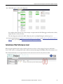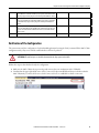
1
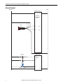
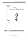
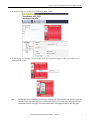
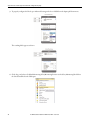
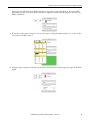
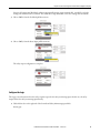
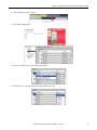
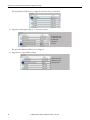
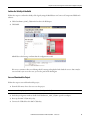
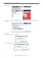
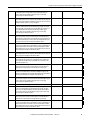
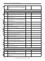
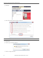
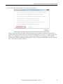
Application Technique
Safety Function: Door-Monitoring Interlock Switch with a
Configurable Safety Relay
Products: SensaGuard Switch, Guardmaster 440C-CR30 Configurable Safety Relay, 100S-C Safety Contactors
Safety Rating: CAT. 4, PLe to ISO 13849-1: 2008
Topic
Page
Important User Information
2
General Safety Information
3
Introduction
3
Safety Function Realization: Risk Assessment
3
Safety-Related Stop Safety Function
4
Safety Function Requirements
4
Functional Safety Description
4
Bill of Material
5
Setup and Wiring
5
Configuration
8
Calculation of the Performance Level
21
Verification and Validation Plan
23
Verification of the Configuration
27
Additional Resources
30
Safety Function: Door-Monitoring Interlock Switch with a Configurable Safety Relay
Important User Information
Read this document and the documents listed in the additional resources section about installation, configuration, and
operation of this equipment before you install, configure, operate, or maintain this product. Users are required to
familiarize themselves with installation and wiring instructions in addition to requirements of all applicable codes, laws,
and standards.
Activities including installation, adjustments, putting into service, use, assembly, disassembly, and maintenance are required
to be carried out by suitably trained personnel in accordance with applicable code of practice.
If this equipment is used in a manner not specified by the manufacturer, the protection provided by the equipment may be
impaired.
In no event will Rockwell Automation, Inc. be responsible or liable for indirect or consequential damages resulting from the
use or application of this equipment.
The examples and diagrams in this manual are included solely for illustrative purposes. Because of the many variables and
requirements associated with any particular installation, Rockwell Automation, Inc. cannot assume responsibility or
liability for actual use based on the examples and diagrams.
No patent liability is assumed by Rockwell Automation, Inc. with respect to use of information, circuits, equipment, or
software described in this manual.
Reproduction of the contents of this manual, in whole or in part, without written permission of Rockwell Automation,
Inc., is prohibited.
Throughout this manual, when necessary, we use notes to make you aware of safety considerations.
WARNING: Identifies information about practices or circumstances that can cause an explosion in a hazardous environment,
which may lead to personal injury or death, property damage, or economic loss.
ATTENTION: Identifies information about practices or circumstances that can lead to personal injury or death, property
damage, or economic loss. Attentions help you identify a hazard, avoid a hazard, and recognize the consequence.
IMPORTANT
Identifies information that is critical for successful application and understanding of the product.
Labels may also be on or inside the equipment to provide specific precautions.
SHOCK HAZARD: Labels may be on or inside the equipment, for example, a drive or motor, to alert people that dangerous
voltage may be present.
BURN HAZARD: Labels may be on or inside the equipment, for example, a drive or motor, to alert people that surfaces may
reach dangerous temperatures.
ARC FLASH HAZARD: Labels may be on or inside the equipment, for example, a motor control center, to alert people to
potential Arc Flash. Arc Flash will cause severe injury or death. Wear proper Personal Protective Equipment (PPE). Follow ALL
Regulatory requirements for safe work practices and for Personal Protective Equipment (PPE).
2
Rockwell Automation Publication SAFETY-AT133C-EN-P - October 2015
Safety Function: Door-Monitoring Interlock Switch with a Configurable Safety Relay
General Safety Information
Contact Rockwell Automation to find out more about our safety risk assessment services.
IMPORTANT
This application example is for advanced users and assumes that you are trained and experienced in safety system requirements.
ATTENTION: Perform a risk assessment to make sure all task and hazard combinations have been identified and addressed. The risk
assessment can require additional circuitry to reduce the risk to a tolerable level. Safety circuits must take into consideration safety
distance calculations, which are not part of the scope of this document.
Introduction
This safety function application example explains how to wire and configure a Guardmaster® 440C-CR30 configurable
safety relay to monitor a SensaGuard™ non-contact interlock switch. The SensaGuard-monitored door allows partial body
access to the guarded area. When that door is opened while the motor is running , or a fault is detected in the monitoring
circuit, the 440C-CR30 configurable safety relay de-energizes the two 100S contactors, removing power from the motor.
The hazardous motion coasts to a stop.
Safety Function Realization: Risk Assessment
The required performance level is the result of a risk assessment and refers to the amount of the risk reduction to be carried
out by the safety-related parts of the control system. Part of the risk reduction process is to determine the safety functions of
the machine. In this application, the performance level required (PLr) by the risk assessment is Category 3, Performance
Level d (CAT. 3, PLd), for each safety function. A safety system that achieves CAT. 3, PLd, or higher, can be considered
control reliable. Each safety product has its own rating and can be combined to create a safety function that meets or
exceeds the PLr.
From: Risk Assessment (ISO 12100)
1. Identification of safety functions
2. Specification of characteristics of each function
3. Determination of required PL (PLr) for each safety function
To: Realization and PL Evaluation
Rockwell Automation Publication SAFETY-AT133C-EN-P - October 2015
3
Safety Function: Door-Monitoring Interlock Switch with a Configurable Safety Relay
Safety-Related Stop Safety Function
This application includes one safety function: Safety-related stop initiated by a SensaGuard switch.
Safety Function Requirements
Opening the door trips the SensaGuard switch and stops the hazardous motion by removing power to the motor. The
hazardous motion coasts to a stop. Once the door is closed and the 440C-CR30 configurable safety relay is reset, power is
not restored to the motor until the motor is given an external Start command (a deliberate second action). Faults at the
SensaGuard switch, wiring terminals, 440C-CR30 configurable safety relay, or 100S contactors are detected before the
next safety demand. This circuit can connect to and interrupt power to motors rated up to 12A, 600V AC.
Personnel must not be able to open the door and reach the hazardous motion before it has stopped. The nearest hazard is a
32-inch reach from the door. Testing has shown that the quickest time between the start of a person opening the door and
that person reaching the nearest hazard is 1.5 seconds.
Calculations, based on the worst-case stopping time, must be done to be certain that the safety system does not permit a
person to open the door and reach a moving hazard. Testing has shown that the worst-case coast-to-stop time is 500 ms.
The total worst-case hazardous motion stop time can be calculated as follows:
Activity
Time (in milliseconds)
SensaGuard switch response (OFF) time
54
440C-CR30 configurable safety relay response (OFF) time
45
100S contactor response (OFF) time
20
Worst-case coast-to-stop time
500
Total worst-case hazardous motion stop time 619
This system fulfills the requirement of assuring that a person cannot reach the nearest hazard while that hazard is moving. If
it is not possible to stop the machine in time (500 ms is quite large), then the designer must use a guard locking switch, for
example the new 440G-LZ, and allow access to the machine only when it has stopped and there are no hazards.
The safety function in this application technique meets or exceeds the requirements for Category 3, Performance Level d
(CAT. 3, PLd), per ISO 13849-1 and control reliable operation per ANSI B11.19.
Functional Safety Description
Personnel are protected from the hazardous motion by a fixed barrier. Access to the hazardous area, when necessary, is
through a swinging door. The door is monitored by a SensaGuard non-contact interlock, which is connected to inputs of
the 440C-CR30 configurable safety relay. The 440C-CR30 relay controls two 100S-C safety contactors which, connected
in a series, control power to the motor that drives the hazardous motion.
Whenever this monitored door is opened, the safety system removes power to the motor. The motor and the hazardous
motion it drives coast to a stop (Stop Category 0). The motor cannot be restarted while the monitored door is open. Once
4
Rockwell Automation Publication SAFETY-AT133C-EN-P - October 2015
Safety Function: Door-Monitoring Interlock Switch with a Configurable Safety Relay
the door is closed, the motor can be restarted by pressing and releasing the Reset button to reset the 440C-CR30 relay and
then initiating the external Start to restore the motor power that is controlled by the 100S-C contactors.
The SensaGuard switch monitors the status (open or closed) of the door. The SensaGuard switch also monitors its two
OSSD outputs for faults. The 440C-CR30 relay monitors the inputs from the SensaGuard switch for faults, and it also
monitors the status of the Reset and Feedback signals from the 100S-C contactors. The relay monitors its own outputs for
faults as well. These outputs control the 100S-C contactors. The 440C-CR30 relay turns off its outputs and removes
power to the motor when a fault is detected. It does not reset until that fault is corrected.
Bill of Material
This application uses these products.
Cat. No.
Description
Qty
440N-Z21S16B
SensaGuard switch, 18 mm plastic, 2 x PNP, 0.2A max., safety output, 10 m cable
1
800FP-R611
800F reset, round plastic (type 4/4X/13, IP66), blue, R , standard pack
1
2080-IQ4OB4
4-channel digital input/output combination module
1
1761-CBL-PM02
Cable; 440C-CR30 configurable safety relay to personal computer, printer cable
1
440C-CR30-22BBB
Guardmaster 440C-CR30 software configured safety relay, PLe SIL 3, 22 safety I/O, embedded serial port, USB
programming port, 2 plug-in slots, 24.0V DC
1
100S-C23EJ23BC
MCS 100S-C safety contactor, 23A, 24V DC (with electric coil), bifurcated contact
2
Setup and Wiring
For detailed information on installing and wiring, refer to the publications listed in the Additional Resources on the back
cover.
System Overview
The SensaGuard interlock switch is used to confirm that the guarded door is in the safe, closed condition. Hazardous
motion is ceased or prevented whenever this door is not closed. In addition to monitoring the state of the guarded door, the
SensaGuard switch monitors its outputs for all fault conditions. The 440C-CR30 configurable safety relay also detects an
open-wire fault, a single-channel fault, or a short to 0V at its SensaGuard switch inputs.
The 440C-CR30 configurable safety relay monitors the pulse-tested outputs that drive the safety contactor coils for all
fault conditions. The proper, safe state of the safety contactors, K1 and K2, is confirmed by the 440C-CR30 configurable
safety relay that is monitoring the feedback signals at SMF2 at start-up.
Rockwell Automation Publication SAFETY-AT133C-EN-P - October 2015
5
Safety Function: Door-Monitoring Interlock Switch with a Configurable Safety Relay
Electrical Schematic
DC Com
24V DC - Class 2
440C-CR30-22BBB
A1
A2
440C-CR30
Configurable Safety
Relay
Bn Rd Yel
Access
Door
Gy
Pk
440N-Z21U16A
EI_00
EO_18
EI_01
EO_19
Bu
2080-IQ4OB4
Feedback
K1
P1_00
Plug-In I/O
K2
P1_01
Reset
800FP-R611PQ10V
6
P1_02
A3
B4
B3
Rockwell Automation Publication SAFETY-AT133C-EN-P - October 2015
Safety Function: Door-Monitoring Interlock Switch with a Configurable Safety Relay
DC Com
24V DC - Class 2
440C-CR30-22BBB
A1
A2
440C-CR30
Configurable Safety
Relay
100S-C23EJ23BC*
EI_00
EO_18
EI_01
EO_19
K1
100S-C23EJ23BC*
K2
L1 L2 L3
External
Start
Stop
K1
K2
M
2080-IQ4OB4
P1_00
P1_01
Plug-In I/O
P1_02
A3
B4
B3
*ISO 13849-2 requires transient suppression across the load as a Basic Safety Principal. The 'EJ' electronic coil provides suitable suppression.
Rockwell Automation Publication SAFETY-AT133C-EN-P - October 2015
7
Safety Function: Door-Monitoring Interlock Switch with a Configurable Safety Relay
Configuration
The 440C-CR30 relay is configured by using Connected Components Workbench™ software, release 6.01 or later. A
detailed description of each step is beyond the scope of this document. Knowledge of the Connected Components
Workbench software is assumed.
Configure the 440C-CR30 Relay
Follow these steps to configure the Guardmaster 440C-CR30 relay in Connected Components Workbench software.
1. In Connected Components Workbench software, choose View and then Device Toolbox.
2. Select 440C-CR30-22BBB.
8
Rockwell Automation Publication SAFETY-AT133C-EN-P - October 2015
Safety Function: Door-Monitoring Interlock Switch with a Configurable Safety Relay
3. In the Project Organizer, double-click Guardmaster_400C_CR30 *.
4. To add the plug-in I/O module called for in this circuit, right-click the left plug-in module space and choose the
2080-IQ4OB4 module.
TIP
The I/O module is shown in standard gray, because it is not a safety I/O module. That is permissible in this application, because it is
not used to connect safety signals. Inputs such as Feedback and Reset button are not considered strict, safety signals. Using the
standard I/O for these non-safety signals can reserve the limited number of safety inputs and outputs for true safety signals.
Rockwell Automation Publication SAFETY-AT133C-EN-P - October 2015
9
Safety Function: Door-Monitoring Interlock Switch with a Configurable Safety Relay
5. Click the Edit Logic button to open the Connected Components Workbench Workspace.
A blank workspace appears.
6. From the View pull-down menu, choose Toolbox.
10
Rockwell Automation Publication SAFETY-AT133C-EN-P - October 2015
Safety Function: Door-Monitoring Interlock Switch with a Configurable Safety Relay
The Toolbox appears.
Configure the Inputs
The Toolbox does not list a SensaGuard Safety Monitoring Function. Follow these steps to configure one.
1. Select Alternative Device.
2. Drag it to the green block in the Safety Monitoring column and release it.
Connected Components Workbench software automatically assigns the first two available inputs, EI_00 and EI_01,
to the device. Leave those as assigned. Connected Components Workbench software automatically assigns the
function name SMF 1 to this block. By default, the software assumes an electro-mechanical device and assigns Test
Sources. The SensaGuard switch has two OSSD outputs and does not require Test Sources.
Rockwell Automation Publication SAFETY-AT133C-EN-P - October 2015
11
Safety Function: Door-Monitoring Interlock Switch with a Configurable Safety Relay
3. To properly configure the block, open Advanced Settings and select 2 OSSD from the Inputs pull-down menu.
The resulting block appears as shown.
4. Click, drag , and release a Feedback Monitoring Safety Monitoring function to the Safety Monitoring block below
the SensaGuard block in the Workspace.
12
Rockwell Automation Publication SAFETY-AT133C-EN-P - October 2015
Safety Function: Door-Monitoring Interlock Switch with a Configurable Safety Relay
Note that Connected Components Workbench software assigns this to input terminal EI_02, the next available
Safety Input terminal. The software assumes that this is a single input and automatically assigns the function name
SMF 2 to this block.
5. Because the circuit requires two inputs, one from each contactor, change the number of inputs to 2, one for the N.C.
contact from each 100S contactor.
6. Assign the inputs to Plug-In terminals PI_00 and PI_01. This avoids unnecessarily using Safety Inputs for feedback
signals.
Rockwell Automation Publication SAFETY-AT133C-EN-P - October 2015
13
Safety Function: Door-Monitoring Interlock Switch with a Configurable Safety Relay
7. Click, drag , and release a Reset safety monitoring function to the Safety Monitoring block below the Feedback
Monitoring block in the Workspace.
Connected Components Workbench software automatically assigns the function name SMF 3 to this block.
8. Reassign the Reset Input to Plug-In terminal PI_02.
Configure the Outputs
Follow these steps to configure the outputs.
1. Click and drag Immediate OFF from the Safety Output Function Blocks section of the Toolbox.
2. Release it on the top block of the Safety Output column in the Workspace.
14
Rockwell Automation Publication SAFETY-AT133C-EN-P - October 2015
Safety Function: Door-Monitoring Interlock Switch with a Configurable Safety Relay
Connected Components Workbench software automatically assigns output terminals EO_18 and EO_19. Pulse
Testing is the default for these terminals. The default Reset Type is Manual. Leave these settings at their defaults.
3. Choose SMF 2 from the Feedback pull-down menu.
4. Choose SMF 3 from the Reset Input pull-down menu.
The safety output configuration is complete.
Configure the Logic
The Logic section determines how the safety outputs respond to the safety monitoring inputs. In this case, the safety
output follows the safety monitoring input directly.
1. Click the blue dot on the right side of the SensaGuard Safety Monitoring input block.
It turns gray.
Rockwell Automation Publication SAFETY-AT133C-EN-P - October 2015
15
Safety Function: Door-Monitoring Interlock Switch with a Configurable Safety Relay
2. Click the blue dot on the left side of the Safety Output block to connect the logic.
The completed logic looks like this.
Configure the Status Indicators
The 440C-CR30 configurable safety relay provides ten user-configurable input status indicator LEDs and six userconfigurable output status indicator LEDs. In many cases, they can be very helpful in installing , commissioning ,
monitoring , and troubleshooting a 440C-CR30 configurable safety relay system. They do not affect the operation of the
system in any way, and it is not necessary to configure them, but they are easy to configure and it is a recommended practice
to use them.
16
Rockwell Automation Publication SAFETY-AT133C-EN-P - October 2015
Safety Function: Door-Monitoring Interlock Switch with a Configurable Safety Relay
1. Click Guardmaster_440C_CR30*.
2. Select LED Configuration.
3. For the Type Filter, choose Terminal Status for LED 0.
4. For LED 0, choose Terminal 00 from the Value pull-down menu.
Rockwell Automation Publication SAFETY-AT133C-EN-P - October 2015
17
Safety Function: Door-Monitoring Interlock Switch with a Configurable Safety Relay
The Status Indicator LED 0 is now configured to show the status of terminal 00.
5. Assign the next four Input LEDs (1…4) in the same manner.
SensaGuard OSSD 1 Status
SensaGuard OSSD 2 Status
SensaGuard Status
Feedback Status
Reset Status
The input status indicator LEDs are now configured.
6. Assign the three output LEDs as follows.
Output Channel 1 Status
Output Channel 2 Status
Safety Output Status
18
Rockwell Automation Publication SAFETY-AT133C-EN-P - October 2015
Safety Function: Door-Monitoring Interlock Switch with a Configurable Safety Relay
Confirm the Validity of the Build
Follow these steps to confirm the validity of the logic by using the Build feature in Connected Components Workbench
software.
1. Click Guardmaster_440C_CR30 in the bar above the Workspace.
2. Click Build.
A Build Succeeded message confirms that the configuration is valid.
If an error or omission is discovered during a build, a message is displayed which details the error so that it may be
corrected. After you correct the error, you need to perform the build again.
Save and Download the Project
Follow these steps to save and download the project.
1. From the File menu, choose Save as to save the project.
IMPORTANT
Saving the project with a new name closes the workspace window(s).
2. In the Project Organizer window, double click Guardmaster_440C_CR30 to open the workspace.
3. Power up the 440C-CR30 safety relay.
4. Connect the USB cable to the 440C-CR30 relay.
Rockwell Automation Publication SAFETY-AT133C-EN-P - October 2015
19
Safety Function: Door-Monitoring Interlock Switch with a Configurable Safety Relay
5. Click Download.
6. In the Connection Browser, expand the AB_VBP-1 Virtual Chassis and select the Guardmaster 440C-CR3022BBB.
7. Click OK.
8. Click Yes to change from Run to Program mode.
9. When the download is complete, click Yes to change from Program to Run mode.
20
Rockwell Automation Publication SAFETY-AT133C-EN-P - October 2015
Safety Function: Door-Monitoring Interlock Switch with a Configurable Safety Relay
10. Click Edit Logic to see the online diagnostics.
Green indicates that a block is True or that an input or output terminal is ON. Flashing green indicates that a Safety
Output Function is ready to be Reset.
The online diagnostics mode of the 440C-CR30 relay can be very helpful during the verification process.
11. Review the information in Calculation of the Performance Level on page 21 and Verification and Validation Plan on
page 23 before proceeding with Verification of the Configuration on page 27.
Calculation of the Performance Level
When properly implemented, this safety-related stop function can achieve a safety rating of Category 4, Performance
Level e (CAT. 4, PLe), according to ISO 13849-1: 2008, as calculated by using the SISTEMA software PL calculation tool.
The minimum Performance Level required (PLr) from the risk assessment for this safety function is PLd.
Rockwell Automation Publication SAFETY-AT133C-EN-P - October 2015
21
Safety Function: Door-Monitoring Interlock Switch with a Configurable Safety Relay
This safety-related stop initiated by a safeguard safety function can be modeled as follows:
Input
Output
Logic
100S
K1
SensaGuard
Switch
440C-CR30
Relay
100S
K2
Subsystem 1
Subsystem 2
Subsystem 3
Because these are electro-mechanical devices, the safety contactors data includes the following :
• Mean Time to Failure, dangerous (MTTFd)
• Diagnostic Coverage (DCavg )
• Common Cause Failure (CCF)
Electro-mechanical devices' functional safety evaluations include the following:
• How frequently they are operated
• Whether they are effectively monitored for faults
• Whether they are properly specified and installed
SISTEMA calculates the MTTFd by using B10d data provided for the contactors, along with the estimated frequency of
use, entered during the creation of the SISTEMA project.
The DCavg (99%) for the contactors is selected from the Output Device table of ISO 13849-1 Annex E, Direct
Monitoring.
The CCF value is generated by using the scoring process outlined in Annex F of ISO 13849-1. The complete CCF scoring
process must be performed when actually implementing an application. A minimum score of 65 must be achieved.
22
Rockwell Automation Publication SAFETY-AT133C-EN-P - October 2015
Safety Function: Door-Monitoring Interlock Switch with a Configurable Safety Relay
Verification and Validation Plan
Verification and validation play important roles in the avoidance of faults throughout the safety system design and
development process. ISO 13849-2 sets the requirements for verification and validation. The standard calls for a
documented plan to confirm that all of the safety functional requirements have been met.
Verification is an analysis of the resulting safety control system. The Performance Level (PL) of the safety control system is
calculated to confirm that the system meets the required Performance Level (PLr) specified. The SISTEMA software is
typically used to perform the calculations and assist with satisfying the requirements of ISO 13849-1.
Validation is a functional test of the safety control system to demonstrate that the system meets the specified requirements
of the safety function. The safety control system is tested to confirm that all of the safety-related outputs respond
appropriately to their corresponding safety-related inputs. The functional test includes normal operating conditions in
addition to potential fault injection of failure modes. A checklist is typically used to document the validation of the safety
control system.
Prior to validating the system, confirm that the Guardmaster 440C-CR30 configurable safety relay has been wired and
configured in accordance with the installation instructions.
Verification and Validation Checklist
General Machinery Information
Machine Name/Model Number
Machine Serial Number
Customer Name
Test Date
Tester Names
Schematic Drawing Number
Input Devices
440N-Z21S16B
Configurable Safety Relay
440C-CR30-22BBB
Variable Frequency Drive
Safety Contactor
100S-C23EJ23BC
Safety Wiring and Relay Configuration
Test Step
Verification
1
Confirm that all components' specifications are suitable for the application. Refer to
Basic Safety Principles and Well-tried Safety Principles from ISO 13849-2.
Pass/Fail
2
Visually inspect the safety relay circuit to confirm that it is wired as documented in the
schematics.
3
Confirm that the configuration in the 440C-CR30 configurable safety relay is the correct,
intended configuration.
Changes/Modifications
Normal Operation Verification - The safety system properly responds to all normal Start, Stop, Reset, E-stop and SensaGuard switch inputs.
Test Step
Verification
Pass/Fail
1
Confirm that no one is in the guarded area.
2
Confirm that the hazardous motion is stopped.
3
Confirm that the door is closed.
Rockwell Automation Publication SAFETY-AT133C-EN-P - October 2015
Changes/Modifications
23
Safety Function: Door-Monitoring Interlock Switch with a Configurable Safety Relay
4
Apply power to the safety system.
5
Confirm that the Terminal 00, Terminal 01, and SMF1 input status indicator LEDs of the
440C-CR30 safety relay are green. Confirm that all output status indicators are OFF.
Confirm that the Power and Run status indicator LEDs are green. Monitor the 440CCR30 safety relay for proper status by using Connected Components Workbench
software.
6
Press and release the Reset button on the 440C-CR30 safety relay. Confirm that the
Terminal 18, Terminal 19, and SOF1 output status indicator LEDs are green. Monitor the
status indicator LEDs for proper operation, and monitor the 440C-CR30 safety relay for
proper status by using Connected Components Workbench software.
7
Confirm that the hazardous motion does not start on powerup.
8
Press and release the drive Start button. Confirm that the hazardous motion begins and
that the machine begins to operate.
9
Press the external Stop button. The machine must stop in its normal, configured
manner. The safety system must not respond.
10
Press and release the external Start button. Confirm that the hazardous motion starts
and the machine begins to operate.
11
Open the guarded door. The safety system must trip. The hazardous motion must stop
within less than 0.7 seconds. Monitor the status indicator LEDs for proper operation and
monitor the 440C-CR30 safety relay for proper status by using Connected Components
Workbench software.
12
Press and release the Reset button on the 440C-CR30 safety relay. The 440C-CR30
configurable safety relay must not respond. Monitor the status indicator LEDs for proper
operation, and monitor the 440C-CR30 safety relay for proper status by using
Connected Components Workbench software
13
Close the guarded door. The machine must not start. The 440C-CR30 safety relay must
not respond. Monitor the status indicator LEDs for proper operation, and monitor the
440C-CR30 safety relay for proper status by using Connected Components Workbench
software.
14
Press and release the Reset button on the 440C-CR30 safety relay. The SOF1 of the 440CCR30 safety relay must energize. The hazardous motion must not start. Monitor the
status indicator LEDs for proper operation, and monitor the 440C-CR30 safety relay for
proper status by using Connected Components Workbench software.
15
Press and release the external Start button. Confirm that the motor starts and that the
machine begins to operate.
Validation of Safe Response to Abnormal Operation - The safety system responds properly to all foreseeable faults with corresponding diagnostics.
SensaGuard and 440C-CR30 Configurable Safety Relay Tests
Test Step
Verification and Validation
1
Keep the guarded door closed. While the hazardous motion continues to run. remove
the SensaGuard OSSD1 wire to terminal EI_00 of the 440C-CR30 safety relay. The 440CCR30 safety relay must trip immediately. The red Fault status indicator LED on the relay
must blink. Monitor all status indicator LEDs for proper operation and monitor the
440C-CR30 safety relay for proper status by using Connected Components Workbench
software.
2
Reconnect the wire to E1_00. The 440C-CR30 safety relay must not respond. Press and
release the Reset button on the 440C-CR30 safety relay. The 440C-CR30 safety relay
must not respond. Monitor all status indicator LEDs for proper operation and monitor
the 440C- CR30 safety relay for proper status by using Connected Components
Workbench software.
3
Open and close the guarded door. The red Fault status LED must be OFF. Monitor all
status indicator LEDs for proper operation, and monitor the 440C-CR30 safety relay for
proper status by using Connected Components Workbench software.
24
Pass/Fail
Rockwell Automation Publication SAFETY-AT133C-EN-P - October 2015
Changes/Modifications
Safety Function: Door-Monitoring Interlock Switch with a Configurable Safety Relay
4
Press and release the Reset button on the 440C-CR30 safety relay. The SOF 1 output on
the 440C-CR30 relay must energize. Monitor all status indicator LEDs for proper
operation, and monitor the 440C-CR30 safety relay for proper status by using
Connected Components Workbench software.
5
Press the external Start button. The machine must start to run. Monitor all status
indicator LEDs for proper operation, and monitor the 440C-CR30 safety relay for proper
status by using Connected Components Workbench software.This step is optional in the
following SensaGuard validation tests (Steps 6 through 27).
6
With the guarded door closed, connect OSSD 1 to 24V DC. After approximately 40
seconds, the SensaGuard switch trips. The 440C-CR30 safety relay trips. The red Fault
status indicator LED on the 440C-CR30 safety relay must blink. The status indicator on
the SensaGuard switch flashes red. Monitor all status indicator LEDs for proper
operation, and monitor the 440C-CR30 safety relay for proper status by using
Connected Components Workbench software.
7
Disconnect OSSD 1 from 24V DC. Neither the SensaGuard switch nor the 440C-CR30
safety relay respond. Press and release the Restart button on the 440C-CR30 safety
relay. Neither the SensaGuard switch nor the 440C-CR30 safety relay respond. Monitor
all status indicator LEDs for proper operation, and monitor the 440C-CR30 safety relay
for proper status by using Connected Components Workbench software.
8
Cycle power to the SensaGuard switch. Approximately five seconds after power is
restored to the SensaGuard switch, its status LED turns steady green. The blinking red
Fault status indicator LED on the 440C-CR30 safety relay turns OFF. Monitor all status
indicator LEDs for proper operation, and monitor the 440C-CR30 safety relay for proper
status by using Connected Components Workbench software.
9
Press and release the Reset button on the 440C-CR30 safety relay. Monitor all status
indicator LEDs for proper operation, and monitor the 440C-CR30 safety relay for proper
status by using Connected Components Workbench software.
10
Connect OSSD 1 to DC COM. The 440C-CR30 safety relay trips immediately. The red Safe
Stop stack light turns ON. The amber Gate 1 stack light turns ON. The red Fault status
indicator LED on the 440C-CR30 safety relay must blink. The status indicator on the
SensaGuard switch flashes red.
11
Disconnect OSSD1 from DC COM. Neither the SensaGuard switch nor the 440C-CR30
safety relay respond. Press and release the Restart button on the 440C-CR30 safety
relay. Neither the SensaGuard switch nor the 440C-CR30 safety relay respond.
12
Cycle power to the SensaGuard switch. Approximately five seconds after power is
restored to the SensaGuard switch, its status indicator LED lights steady green. The
amber Gate 1 stack light turns OFF. The red Safe Off stack light remains ON. The blinking
red Fault status indicator LED on the 440C-CR30 safety relay turns OFF.
13
Press and release the Reset button on the 440C-CR30 safety relay. The 440C-CR30 safety
relay's SOF 1 must energize the contactors. Monitor all status indicator LEDs for proper
operation, and monitor the 440C-CR30 safety relay for proper status by using
Connected Components Workbench software.
14 to 27
Repeat steps 1 through 13 using EI_01 in place of EI_00, and OSSD 2 in place of OSSD 1.
28
Connect OSSD 1 to OSSD 2 (terminal EI_00 to terminal EI_01). After approximately 50
seconds, the SensaGuard switch trips. The 440C-CR30 safety relay trips. The status
indicator on the SensaGuard switch flashes red. Monitor all status indicator LEDs for
proper operation, and monitor the 440C-CR30 safety relay for proper status by using
Connected Components Workbench software.
29
Disconnect OSSD 1 from OSSD 2. Neither the SensaGuard switch nor the 440C-CR30
safety relay respond. Press and release the Restart button on the 440C-CR30 safety
relay. Neither the SensaGuard switch nor the 440C-CR30 safety relay respond.
30
Cycle power to the SensaGuard switch. Approximately five seconds after power is
restored to the SensaGuard switch, its status LED turns steady green. The blinking red
Fault status indicator LED on the 440C-CR30 safety relay turns OFF. Monitor all status
indicator LEDs for proper operation, and monitor the 440C-CR30 safety relay for proper
status by using Connected Components Workbench software.
Rockwell Automation Publication SAFETY-AT133C-EN-P - October 2015
25
Safety Function: Door-Monitoring Interlock Switch with a Configurable Safety Relay
31
Press and release the Reset button on the 440C-CR30 safety relay. The red Safe Stop
stack light must be OFF. The SOF1 output on the 440C-CR30 safety relay must energize
the contactors. Monitor all status indicator LEDs for proper operation, and monitor the
440C-CR30 safety relay for proper status by using Connected Components Workbench
software.
Validation of Safe Response to Abnormal Operation - The safety system responds properly to all foreseeable faults with corresponding diagnostics.
Contactor - 440C-CR30 Configurable Safety Relay Tests
Test Step
Verification and Validation
Pass/Fail
1
While the machine continues to run, break the connection between terminal EO_18 of
the 440C-CR30 configurable safety relay and the A1 terminal of the K1 coil. The
hazardous motion must coast to a stop.
2
Press the external Stop button. Restore the connection. Press the external Start button
to resume the hazardous motion.
3
While the hazardous motion continues to run, connect the A1 terminal of the K1 coil to
24V DC. After approximately 18 seconds, the 440C-CR30 safety relay must trip. K2 must
de-energize. The hazardous motion coasts to a stop. The red Fault status indicator LED
on the 440C-CR30 safety relay is ON.
4
Disconnect the A1 terminal of the K1 coil from 24V DC. Press and release the Reset
button on the 440C-CR30 safety relay. The 440C-CR30 safety relay must not respond.
5
Cycle power to the 440C-CR30 safety relay. It responds. The 440C-CR30 safety relay Fault
status indicator LED is OFF.
6
Press and release the Reset button on the 440C-CR30 safety relay. Press the external
Start button. The hazardous motion must resume.
7
While the machine continues to run, short the A1 terminal of the K1 coil to DC COM. The
440C- CR30 safety relay must trip. The red Fault status indicator LED on the 440C-CR30
safety relay is ON.
8
Disconnect the A1 terminal of the K1 coil from DC COM. Press and release the Reset
button on the 440C-CR30 safety relay. The 440C-CR30 safety relay must not respond.
9
Cycle power to the 440C-CR30 safety relay. The 440C-CR30 safety relay responds. The
Fault status indicator LED on the 440C-CR30 safety relay is OFF.
10
Press and release the Reset button on the 440C-CR30 safety relay. Press the external
Start button. The hazardous motion resumes.
11 to 21
Repeat steps 1 to 10 using EO_19 in place of EO_18, and K2 in place of K1.
22
Connect the A1 terminal of K1 to the A1 terminal of K2. After approximately 18 seconds,
the 440C-CR30 safety relay must trip. The hazardous motion coasts to a stop. The red
Fault status indicator LED on the 440C-CR30 safety relay is ON.
23
Disconnect the A1 terminal of K1 from the A1 terminal of K2. Press and release the
Reset button on the 440C- CR30 safety relay. The 440C-CR30 safety relay must not
respond.
24
Cycle power to the 440C-CR30 safety relay. It responds. The Fault status indicator LED on
the 440C-CR30 safety relay is OFF.
25
Press and release the Reset button on the 440C-CR30 safety relay. Press the external
Start button. The hazardous motion must resume.
Changes/Modifications
Validation of Safe Response to Abnormal Operation - The safety system responds properly to all foreseeable faults with corresponding diagnostics.
Contactor Feedback - 440C-CR30 Configurable Safety Relay Tests
Test Step
Verification and Validation
1
While the machine continues to run, remove the K1 feedback connection at terminal
P1_00. The machine must continue to run.
2
Open the guarded door. The safety system must trip. The hazardous motion must stop
within less than 0.7 seconds. Monitor the status indicator LEDs for proper operation,
and monitor the 440C-CR30 relay for proper status by using the Connected Components
Workbench software.
26
Pass/Fail
Rockwell Automation Publication SAFETY-AT133C-EN-P - October 2015
Changes/Modifications
Safety Function: Door-Monitoring Interlock Switch with a Configurable Safety Relay
3
Close the guarded door . The machine must not start. The 440C-CR30 relay must not
respond. Monitor the status indicator LEDs for proper operation, and monitor the 440CCR30 relay for proper status by using the Connected Components Workbench software.
4
Press and release the Reset button on the 440C-CR30 safety relay. The 440C-CR30 relay
must not respond. Monitor the status indicator LEDs for proper operation, and monitor
the 440C-CR30 relay for proper status by using Connected Components Workbench
software.
5
Replace the connection at P1_00. Cycle power to the 440C-CR30 relay. Press the Reset
button on the 440C-CR30 relay. The 440C-CR30 relay outputs must energize. Press and
release the external Start button. Confirm that the motor starts and that the machine
begins to operate.
6
Repeat steps 1 thru 5 using the K2 feedback connection at terminal P1_01.
Verification of the Configuration
The system must verify the configuration of each individual application by using the Verify command. If the 440C-CR30
configuration safety relay is not verified, it will fault after 24 hours of operation.
ATTENTION: The verification process should be documented in the safety system's technical file.
Follow these steps to download and verify the configuration.
1. Make sure the 440C-CR30 relay is powered up and connected to your workstation via the USB cable.
2. Confirm that the upper right-hand corner of the Connected Components Workbench Project tab shows that the
440C-CR30 relay is connected. If it is not, click Connect to Device to establish the software connection.
Rockwell Automation Publication SAFETY-AT133C-EN-P - October 2015
27
Safety Function: Door-Monitoring Interlock Switch with a Configurable Safety Relay
3. Click Verify.
4. Answer all the questions and check each box, if completed.
IMPORTANT
All of the boxes must be marked in order to Generate the Verification ID.
5. Click Generate.
6. Click Yes to proceed with the verification.
7. Click Yes to change to Run mode.
28
Rockwell Automation Publication SAFETY-AT133C-EN-P - October 2015
Safety Function: Door-Monitoring Interlock Switch with a Configurable Safety Relay
8. Record the Safety Verification ID in the machine's documentation.
This process is the feedback to the 440C-CR30 relay that the system verification and functional tests have been
completed. The unique verification ID can be used to check if changes have been made to a configuration file. Any
change to the configuration removes the Safety Verification ID. Subsequent Verify actions generate a different
verification ID. The Safety Verification ID is displayed in Connected Components Workbench software only when
you are connected to the 440C-CR30 relay.
Rockwell Automation Publication SAFETY-AT133C-EN-P - October 2015
29
Safety Function: Door-Monitoring Interlock Switch with a Configurable Safety Relay
Additional Resources
These documents contain additional information concerning related products from Rockwell Automation.
Resource
Description
SensaGuard18 mm Plastic Barrel Installation Instructions, publication 440N-IN010
Provides detailed information on how to install, configure, wire, operate, and
troubleshoot a unique coded SensaGuard 18 mm plastic barrel.
Guardmaster 440C-CR30 Software Configurable Safety Relay Quick Start Guide, publication
440C-QS001
Provides information on how to configure a Guardmaster 440C-CR30 configurable
safety relay to communicate with a PanelView Component terminal via Modbus
communication protocol.
Guardmaster 440C-CR30 Configurable Safety Relay User Manual, publication 440C-UM001
Provides detailed information on how to install, configure, operate, and troubleshoot
a Guardmaster 440C-CR30 configurable safety relay.
Safety Contactors with DC Coil Installation Instructions, publication 100S-IN006
Provides instructions on how to install 100S safety contactors.
Industrial Automation Wiring and Grounding Guidelines, publication 1770-4.1
Provides general guidelines on how to install a Rockwell Automation® industrial
system.
Safety Products Catalog, publication S117-CA001
website http://www.rockwellautomation.com/rockwellautomation.com/catalogs/
overview.page
Provides information about Rockwell Automation safety products.
Product Certifications website, available from the Product Certifications link on http://
www.ab.com
Provides declarations of conformity, certificates, and other certification details.
Rockwell Automation Safety Resource Center, http://discover.rockwellautomation.com/
SFTY_EN_tools.aspx
Provides information about Safety Automation Builder, the Safety Evaluator Tool, and
the SISTEMA tool. Lets you download the SISTEMA tool, as well as Rockwell
Automation SISTEMA libraries and safety functions.
The SISTEMA Cookbook 1, available at http://www.dguv.de/ifa/Praxishilfen/Software/
SISTEMA/SISTEMA-Kochb%C3%BCcher/index-2.jsp
Provides details on how to model safety functions in the SISTEMA tool.
You can view or download publications at http://www.rockwellautomation.com/literature/. To order paper copies of
technical documentation, contact your local Allen-Bradley® distributor or Rockwell Automation sales representative.
30
Rockwell Automation Publication SAFETY-AT133C-EN-P - October 2015
Safety Function: Door-Monitoring Interlock Switch with a Configurable Safety Relay
Notes:
Rockwell Automation Publication SAFETY-AT133C-EN-P - October 2015
31
Documentation Feedback
Your comments will help us serve your documentation needs better. If you have any suggestions on how to improve this
document, complete this form, publication RA-DU002, available at http://www.rockwellautomation.com/literature/.
For more information on
Safety Function Capabilities, visit:
http://marketing.rockwellautomation.com/safety/en/safety_functions
Rockwell Automation maintains current product environmental information on its website at
http://www.rockwellautomation.com/rockwellautomation/about-us/sustainability-ethics/product-environmental-compliance.page.
Allen-Bradley, Connected Components Workbench, Guardmaster, LISTEN. THINK. SOLVE, Rockwell Automation, Rockwell Software, and SensaGuard are trademarks of Rockwell Automation, Inc.
Trademarks not belonging to Rockwell Automation are property of their respective companies.
Rockwell Otomasyon Ticaret A.Ş., Kar Plaza İş Merkezi E Blok Kat:6 34752 İçerenköy, İstanbul, Tel: +90 (216) 5698400
Publication SAFETY-AT133C-EN-P - October 2015
Supersedes Publication SAFETY-AT133B-EN-P - November 2014
Copyright © 2015 Rockwell Automation, Inc. All rights reserved. Printed in the U.S.A.