1
Examination Project carried out within the context of a
joint study programme of
UNIVERSITY OF SKÖVDE, SWEDEN
and
DE MONTFORT UNIVERSITY, UK
September 2002
Bluetooth för mobila robotar (communications
moduler)
Bluetooth for mobile robots (communication units)
Examensarbete utfört av Andreas Eriksson på D-nivå
för erhållande av Magister.
Under handledning av:
Professor P.R. Moore, De Montfort University, UK
Thomas Karlsson and Nicklas Bergfeldt, HiS, Sweden
Faculty of Computer Science and Engineering
Department of Mechanical and Manufacturing Engineering
“Bluetooth for mobile robots
(communication units)”
A MSc. project presented to De Montfort University in partial fulfilment of the
requirements of the Degree of Master of Science in Mechatronics.
Submitted by:
Andreas Eriksson
September 2002
Supervised by:
Professor P.R. Moore, Mr Thomas Karlsson and Mr Nicklas Bergfeldt
Master Thesis. “Bluetooth for mobile robots (communication units)”
2002-09-20
Abstract
This project has been carried out on the Engineering Science Department and Computer
Science Department at the University of Skövde in Sweden.
The aim of the project was to develop a wireless multi-robot network system for the Khepera
mini-robot platform. The network aimed to support real-time control of up to four robots from
a host computer. To support multi-robot research in ANN and AI related areas. The project
was divided in two parts where one of them was concentrating on the development of a base
station connected to a PC. The other part focused on the development of the communication
units used on the robots, which is the part described in this Master Dissertation.
A system contained of both hardware and software was designed to enable the robots to
participate in the multi-robot network. The wireless communication was performed by using
Bluetooth communication. The primary parts of the hardware developed was the connection
to the robot (K-Bus), the microcontroller, the Bluetooth device, voltage regulator and a RS232 line driver.
A multi-file software developed in ANSI C was engineered to be embedded in the
microcontroller. An embedded Bluetooth stack was created to support the robots to work as
slaves in the multi-robot network. The main task of the software was to collect data sent from
the robot and translate it into information to send via the Bluetooth radio media to the base
station. The software also supported the opposite operation for information flowing from the
base station to the robot.
The hardware and software developed in this part of the project was fully integrated and the
translations performed by the software was tested to be under 0.1 milliseconds, which was
sufficient. Real-time control of one robot was performed, but a multi-robot network was
unfortunately not achieved due to the Bluetooth stack used in the other part of the project.
Keywords: Bluetooth, Real-time control, multi-robot network and embedded Bluetooth stack.
De Montfort University
Faculty of Computing Sciences and Engineering
MSc Mechatronics 2001/2002
i
Andreas Eriksson
Master Thesis. “Bluetooth for mobile robots (communication units)”
2002-09-20
Acknowledgements
One of the most pleasant parts of writing a report is the opportunity to thank those who have
contributed to the accomplished work. The list of thanks is always inadequate.
First I would like to express my sincere gratitude and appreciation to all my supervisors at the
University of Skövde facilitating and making the project possible to carry out. The Ph.D.
students at the Centre of Intelligent Automation, Mr Thomas Karlsson and Mr Amos NG for
providing good facilities and support during the finalising of the dissertation. Then, Mr
Nicklas Bergfelt supervisor from the Computer Science Department, which was the originator
of the project. Also the nice people at the Engineering Science Department Mr Stefan Ericson,
Mr Klas Hedenberg and Mr Stefan Zomborcsevics for irreplaceable advises and huge
engagement. My thanks and appreciation is also to the staff at De Montfort University in
Leicester where I especially want to thank the program leader and supervisor Professor P.R.
Moore.
I also want to thank my colleague and friend Mr Kari Karvosenoja who developed the other
part of the project.
Finally, I would like to express my gratitude to my family and friends for their continuos
support and encouragement throughout my years in school.
De Montfort University
Faculty of Computing Sciences and Engineering
MSc Mechatronics 2001/2002
ii
Andreas Eriksson
Master Thesis. “Bluetooth for mobile robots (communication units)”
2002-09-20
Table of Contents
Abstract ...................................................................................................................................... i
Acknowledgements................................................................................................................... ii
Table of Contents ....................................................................................................................iii
List of Figures ......................................................................................................................... vii
List of Tables............................................................................................................................ ix
List of Abbreviations................................................................................................................ x
List of Definitions ..................................................................................................................... x
1
Introduction ...................................................................................................................... 1
1.1
Background ................................................................................................................ 1
1.2
Project aim ................................................................................................................. 3
1.3
Project overview......................................................................................................... 3
1.3.1
Khepera Bluetooth Unit ..................................................................................... 4
1.3.2
Radio Base Station ............................................................................................. 5
1.4
The need for a fast wireless connection ..................................................................... 5
1.5
Project objectives ....................................................................................................... 6
1.6
Expected project outcomes......................................................................................... 7
1.7
Project approach........................................................................................................ 7
1.7.1
Analysis stage..................................................................................................... 7
1.7.2
Research stage .................................................................................................... 8
1.7.3
Development stage ............................................................................................. 8
1.7.4
Final stage .......................................................................................................... 9
1.7.5
Gantt chart .......................................................................................................... 9
1.8
Outline of this report ................................................................................................ 11
De Montfort University
Faculty of Computing Sciences and Engineering
MSc Mechatronics 2001/2002
iii
Andreas Eriksson
Master Thesis. “Bluetooth for mobile robots (communication units)”
2
Literature review............................................................................................................ 12
2.1
Methods for wireless communication....................................................................... 12
2.1.1
Wireless Network Topologies.......................................................................... 12
2.1.2
Available wireless technologies ....................................................................... 13
2.1.3
Choise of wireless technology.......................................................................... 15
2.2
Control of mobile robots over Bluetooth.................................................................. 16
2.2.1
The Bluetooth Controlled Beetle...................................................................... 16
2.2.2
Radio Controlled Robot Car............................................................................. 18
2.3
Wireless control of the Khepera platform ................................................................ 19
2.3.1
Khepera Radio Turret....................................................................................... 20
2.3.2
Communication with Khepera robots over a CAN infrared network .............. 21
2.4
3
2002-09-20
Embedded Bluetooth research ................................................................................. 23
2.4.1
PlayMobile ....................................................................................................... 23
2.4.2
The BlueNurse Wireless Link .......................................................................... 24
Design specification ........................................................................................................ 27
3.1
Specification of requirements................................................................................... 27
3.1.1
General requirements ....................................................................................... 27
3.1.2
Hardware requirements .................................................................................... 28
3.1.3
Software requirements...................................................................................... 28
3.1.4
Link requirements ............................................................................................ 29
3.2
Specification of the control loop .............................................................................. 29
3.3
Hardware specifications .......................................................................................... 30
3.3.1
K-bus ................................................................................................................ 30
3.3.2
Circuit board..................................................................................................... 32
3.3.3
Wiring specifications........................................................................................ 33
3.3.4
Microcontroller................................................................................................. 34
3.3.5
Bluetooth device............................................................................................... 35
3.3.6
Antenna ............................................................................................................ 37
3.3.7
Hardware functions .......................................................................................... 38
De Montfort University
Faculty of Computing Sciences and Engineering
MSc Mechatronics 2001/2002
iv
Andreas Eriksson
Master Thesis. “Bluetooth for mobile robots (communication units)”
3.4
4
Software specifications............................................................................................. 40
3.4.1
Bluetooth protocol stack................................................................................... 40
3.4.2
Khepera protocol .............................................................................................. 43
3.4.3
Application Programmable Interface ............................................................... 44
3.4.4
Software structure ............................................................................................ 44
3.4.5
Software functions............................................................................................ 44
3.5
Specification of data packets.................................................................................... 45
3.6
Tool specification ..................................................................................................... 47
Hardware implementation ............................................................................................ 49
4.1
Conceptual design .................................................................................................... 49
4.2
Bluetooth Core Board design................................................................................... 50
4.2.1
Producing the Printed Circuit Board ................................................................ 52
4.2.2
Verification of the Bluetooth Core Board ........................................................ 54
4.3
5
2002-09-20
Khepera Bluetooth Unit design ................................................................................ 55
4.3.1
Producing the Printed Circuit Board ................................................................ 58
4.3.2
Verification of the Khepera Bluetooth Unit ..................................................... 60
Software implementation............................................................................................... 61
5.1
Conceptual design .................................................................................................... 61
5.1.1
State diagram.................................................................................................... 61
5.1.2
Interrupts and polling ....................................................................................... 62
5.2
The embedded software............................................................................................ 63
5.2.1
Global functions and variables......................................................................... 64
5.2.2
Initialisation...................................................................................................... 64
5.2.3
Main ................................................................................................................. 67
5.2.4
HCI Layer......................................................................................................... 69
5.2.5
UART ............................................................................................................... 72
5.2.6
Khepera ............................................................................................................ 74
5.3
Software verification ................................................................................................ 74
De Montfort University
Faculty of Computing Sciences and Engineering
MSc Mechatronics 2001/2002
v
Andreas Eriksson
Master Thesis. “Bluetooth for mobile robots (communication units)”
6
2002-09-20
Tests ................................................................................................................................. 76
6.1
Current consumption test ......................................................................................... 76
6.2
Test of the communication chain.............................................................................. 77
6.2.1
Test set-up ........................................................................................................ 77
6.2.2
Measurements................................................................................................... 78
6.2.3
Calculations of the known delays..................................................................... 81
6.2.4
Delay caused by the entire communication chain............................................ 81
6.3
Real-time control test ............................................................................................... 82
7
Discussion and results .................................................................................................... 84
8
Conclusions and future work ........................................................................................ 88
8.1
Conclusions .............................................................................................................. 88
8.2
Proposals for future works....................................................................................... 90
References ............................................................................................................................... 91
Appendix A; Bluetooth Protocol Stack Basics
Appendix B; Bluetooth Network Topology
Appendix C; Detailed Bus Placement
Appendix D; Schematics
Appendix E; Bill Of Materials
Appendix F; Source Code
De Montfort University
Faculty of Computing Sciences and Engineering
MSc Mechatronics 2001/2002
vi
Andreas Eriksson
Master Thesis. “Bluetooth for mobile robots (communication units)”
2002-09-20
List of Figures
Figure 1. Khepera mobile robot. [ANON 2002 a]..................................................................... 2
Figure 2. System overview. ........................................................................................................ 3
Figure 3. Main components and interfaces of the KBU............................................................. 4
Figure 4. Main components and interfaces of the RBS.............................................................. 5
Figure 5. Scheduling of MSc Project. ...................................................................................... 10
Figure 6. The Bluetooth controlled Beetle. [Brodin & Nilsson 2000]..................................... 17
Figure 7. Control configuration for the Beetle. [Brodin & Nilsson 2000] .............................. 17
Figure 8. Hardware solution of the BCC. [Brodin & Nilsson 2000]....................................... 18
Figure 9. Radio Controlled Robot Car. [Dijkstra & Martena 2000] ...................................... 18
Figure 10. Architectural overview for the Robot Car. [Dijkstra & Martena 2000]................ 19
Figure 11. Overview of the Khepera radio base and turret system. [K-Team 1999 b] ........... 20
Figure 12. Khepera radio turret. [ANON 2002 a]................................................................... 21
Figure 13. Overview of the CAN infrared network. [Odenbach 1999] ................................... 22
Figure 14. Top view of the CAN infrared turret. [Odenbach 1999] ........................................ 22
Figure 15. PlayMobile solutions. [Gunée & Iranpour 2000].................................................. 24
Figure 16. Block schematic of the PlayMobile serial solution. [Gunée & Iranpour 2000] .... 24
Figure 17. BlueNurse Block diagram. [Naveenan 2001] ........................................................ 25
Figure 18. Schematics of the BlueNurse wireless link. [Naveenan 2001] ............................... 25
Figure 19. Control loop for controlling a robot from the host computer. ............................... 30
Figure 20. K-Bus overview....................................................................................................... 30
Figure 21. Typical module for the Khepera robot. [ANNON 2002 a]..................................... 32
Figure 22. Mechanical bus constraint. [K-Team 1999 a] ....................................................... 33
Figure 23. Bluetooth device. [Ericsson 2001] ......................................................................... 35
Figure 24. Interfaces of the Bluetooth device. [Ericsson 2001] .............................................. 36
Figure 25. General software design......................................................................................... 40
Figure 26. Lower layers of the Bluetooth software stack. [Bluetooth SIG 2001].................... 41
Figure 27. HCI UART transport layer. [Bluetooth SIG 2001] ................................................ 42
Figure 28. Format specification of a Khepera control command. [K-Team 1999 a].............. 43
Figure 29. Example of a multi-file software structure. [Brodin & Nilsson 2000]................... 44
Figure 30. The two major parts of an ACL data packet. ......................................................... 45
Figure 31. Packet header. ........................................................................................................ 46
Figure 32. Hardware concept. ................................................................................................. 49
De Montfort University
Faculty of Computing Sciences and Engineering
MSc Mechatronics 2001/2002
vii
Andreas Eriksson
Master Thesis. “Bluetooth for mobile robots (communication units)”
2002-09-20
Figure 33. ROK 101 007 BGA pin connection......................................................................... 50
Figure 34. Suyin BT socket. ..................................................................................................... 51
Figure 35. Titanis Swivel Bluetooth antenna. .......................................................................... 51
Figure 36. Bluetooth Core Board. ........................................................................................... 52
Figure 37. Screen dump of TXLINE 2001................................................................................ 53
Figure 38. Bluetooth Core Board PCB.................................................................................... 53
Figure 39. Radio Base Station. ................................................................................................ 54
Figure 40. Interface of SimpleConnectC.................................................................................. 54
Figure 41. Microcontroller socket. .......................................................................................... 56
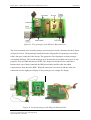
Figure 42. First prototype of the Khepera Bluetooth Unit. ..................................................... 57
Figure 43. Second prototype of the Khepera Bluetooth Unit................................................... 57
Figure 44. Khepera Bluetooth Unit PCB layout proposal....................................................... 59
Figure 45. Test of the transceiver circuit................................................................................. 60
Figure 46. Software state diagram........................................................................................... 62
Figure 47. Interrupt and polling relationship.......................................................................... 63
Figure 48. File structure. ......................................................................................................... 64
Figure 49. Flowchart of the initialisation process................................................................... 65
Figure 50. Examples of robot ID and baud rate settings......................................................... 66
Figure 51. Flow chart of the main function. ............................................................................ 68
Figure 52. Flowchart for UART transmission and reception. ................................................. 73
Figure 53. Screen shot of COM Test........................................................................................ 75
Figure 54. Current consumption test of the KBU prototype. ................................................... 77
Figure 55. Communication chain............................................................................................. 78
Figure 56. Screen shot of the logic analyser............................................................................ 78
Figure 57. Measurements of the Bluetooth throughput. [Hörjel 2001]................................... 80
Figure 58. Timing diagram. ..................................................................................................... 81
Figure 59. Interface of the Radio Base Station software. ........................................................ 82
De Montfort University
Faculty of Computing Sciences and Engineering
MSc Mechatronics 2001/2002
viii
Andreas Eriksson
Master Thesis. “Bluetooth for mobile robots (communication units)”
2002-09-20
List of Tables
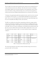
Table 1. Pin specification. (Redrawn from [3]) ....................................................................... 31
Table 2. Electrical specification for the K-bus interface. [K-Team 2001] .............................. 32
Table 3. Power consumption for ROK 101 007. [Ericsson 2001] ........................................... 36
Table 4. Complete set of robot ID and baud rate settings. ...................................................... 67
De Montfort University
Faculty of Computing Sciences and Engineering
MSc Mechatronics 2001/2002
ix
Andreas Eriksson
Master Thesis. “Bluetooth for mobile robots (communication units)”
2002-09-20
List of Abbreviations
AP – Access Point
API – Application Programmable Interface
BCB – Bluetooth Core Board
bps – bits per second
BT– Bluetooth
KBU – Khepera Bluetooth Unit
LSB – Least Significant Bit
LSByte – Least Significant Byte
MCU – Micro Controller Unit
MSB – Most Significant Bit
MSByte – Most Significant Byte
PAN – Personal Area Network
PC – Personal Computer
PCB – Printed Circuit Board
Rx – Receive
RBS – Radio Base Station
SIG – Special Interest Group
Tx – Transmit
UART – Universal Asynchronous Receiver Transmitter
USART – Universal Synchronous / Asynchronous Receiver Transmitter
List of Definitions
Baud rate – Bits per second
Byte – 8 bit long data word
Char – Character, 8 bit long data type
Unsigned – The MSB of the data type becomes a value instead of an indication of plus or
minus.
De Montfort University
Faculty of Computing Sciences and Engineering
MSc Mechatronics 2001/2002
x
Andreas Eriksson
Master Thesis. “Bluetooth for mobile robots (communication units)”
2002-09-20
1 Introduction
The aim of this chapter was to give an overview of the project and the Master thesis. A brief
introduction of the Computer Science department at the University of Skövde is given. The
aims and objectives of the project are then addressed.
1.1
Background
The Computer Science Department at the University of Skövde are among other things
performing research in Artificial Intelligence (AI) and Artificial Neural Networks (ANN)
related areas. The department is closely following the front line technology and research in
these areas and they are very familiar with using the Khepera robots in their research. The
Computer Science Department have developed there own simulator and controlling software
for the Khepera robots called YAKS (Yet Another Khepera Simulator).
Khepera is a miniature mobile robot with functionality similar to that of larger robots used in
research and education. It allows real-world testing of the algorithms that are developed in
simulations for trajectory planning, obstacle avoidance, pre-processing of sensory
information, and hypotheses on behaviour processing, etc. Four robots of this type are
currently being used for this purpose in the Computer Science Department. [K-Team 1999 a]
The Khepera robot (see figure 1) has the following features: [K-Team 1999 a]
•
Small (50 mm in diameter) in order to be used on a table.
•
Modular in order to fit to a large number of needs.
•
Easy to use by the connection to standard and well-known tools.
•
Dead reckoning is used to determine its present location and eight Infrared sensors for
obstacle avoidance.
De Montfort University
Faculty of Computing Sciences and Engineering
MSc Mechatronics 2001/2002
1
Andreas Eriksson
Master Thesis. “Bluetooth for mobile robots (communication units)”
2002-09-20
Figure 1. Khepera mobile robot. [ANON 2002 a]
As the robots are used for education and research of ANN and AI related areas there are rather
demanding calculations involved. The calculations are not executed onboard the robots, thus
connection to a host computer is required. Sensor information should be sent from the robots
to the host computer and control commands for the motors in the opposite direction.
There were two ways of connecting the robots to the host computer that executed the
calculations and sent the control commands. Connection via RS-232 cable, which was
relatively fast but the cables were easily tangled when several robots were used
simultaneously. The cable problem was solved by using a radio communication module for
sending and receiving information to and from the host computer for further calculations.
However, the current radio link was too slow for handling more than one robot at the same
time. If more sensors or other equipment e.g. a camera was added, the requirement of the
radio link became even higher.
The fact that none of these two ways of connecting several robots to the host computer were
successful, constrained the research in multi-robot systems. The design of a solution with a
fast wireless communication link to eliminate the problem with tangled cables and still
provide a real-time communication was desired.
De Montfort University
Faculty of Computing Sciences and Engineering
MSc Mechatronics 2001/2002
2
Andreas Eriksson
Master Thesis. “Bluetooth for mobile robots (communication units)”
1.2
2002-09-20
Project aim
The aim of this project was to develop a wireless multi-robot network system for the Khepera
platform to the Computer Science Department at the University of Skövde. The network
should support real-time control of up to four robots from a host computer. To support multirobot research, wireless communication was required to get rid of all cables used for
communicating with the robots. A system containing both hardware and software was about
to be designed to replace the cables.
The aim was to design the system to support the communication strategy used for controlling
the Khepera robots. The robots were slaves and acted on the commands sent from the host
computer, which was master. One aim was to design the system as simple as possible to not
effect the functionality’s already adopted by the Khepera platform. The system should be of
cable replacing nature.
The project also aimed to evaluate and test Bluetooth technology in real-time control of the
Khepera mobile robots.
1.3
Project overview
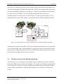
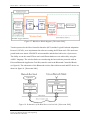
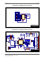
The project considered a system wireless connecting several robots to PC via a base station.
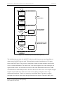
An overview of the system consisting of both hardware and software is illustrated in figure 2.
Figure 2. System overview.
De Montfort University
Faculty of Computing Sciences and Engineering
MSc Mechatronics 2001/2002
3
Andreas Eriksson
Master Thesis. “Bluetooth for mobile robots (communication units)”
2002-09-20
The system illustrated in figure 2 can be divided into two major parts, which also divided the
project between the two project members.
1. Design and implement Bluetooth communication units for the Khepera mobile robots.
2. Design and implementat a Bluetooth base station, interfaced to a host computer.
This Master Thesis focused on the design solution required for the robots only and no
emphasis was on the design of the base station for the host computer. Mr Kari Karvosenoja
performed the other part. The parts are briefly described in the two following sections to give
the reader an idea of the outcome of the project.
1.3.1
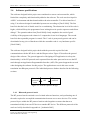
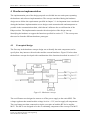
Khepera Bluetooth Unit
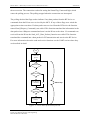
The Bluetooth (BT) communication unit for the Khepera mobile robot was called Khepera
Bluetooth Unit (KBU). The KBU was designed to be a modular unit to the Khepera robot
used to communicate control commands with the host computer. The design of the KBU was
fixed to basically be a circuit board connected to the data bus (called the K-bus) of the
Khepera robot. The circuit board contained several sophisticated electric components.
Simplified the main components identified were a Bluetooth device, a microcontroller and an
antenna (see figure 3). The microcontroller run an embedded software with the protocols both
dealing with the interfaces to the K-bus and the Bluetooth chip.
Wireless
communication
Circuit board
Khepera
mobile
robot
K-bus
Microcontroller
Communication
Interface
Bluetooth
device
Figure 3. Main components and interfaces of the KBU.
De Montfort University
Faculty of Computing Sciences and Engineering
MSc Mechatronics 2001/2002
4
Andreas Eriksson
Master Thesis. “Bluetooth for mobile robots (communication units)”
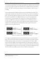
1.3.2
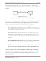
2002-09-20
Radio Base Station
The complete BT base station application with hardware and software was referred to as the
Radio Base Station (RBS). A basic block diagram of the RBS design is illustrated in figure 4.
The RBS hardware consisted of electronic components that enabled serial communication
with a host computer trough the comport, a BT device together with an antenna and power
supply circuits. The Bluetooth software stack, C-Stack, was implemented in the RBS host
computer. It was also attempted to be interfaced to the ANN simulator software YAKS by an
Application Programmable Interface (API). The stack was connected to the Bluetooth chip via
a communication interface.
Wireless
communication
RBS Hardware
RBS Software in the host computer
Communication
YAKS
C-Stack
Interface
Bluetooth
chip
API
Figure 4. Main components and interfaces of the RBS.
1.4
The need for a fast wireless connection
Before the project started it was impossible to connect more than one robot to the comport of
the host computer. When using up to four robots connected with cables restricted the robots in
their movements. The current problems with the existing techniques of connecting several
robots to a host computer constrained the research in multi-robot systems. The design of a
solution with a fast wireless communication link was to eliminate the problem e.g. with
tangled cables and still provide a real-time communication.
When BT was used the distance between the host computer and the robots were dramatically
improved from two meters (by cable) up to ten, which gives freedom for the user to build
more complex research applications.
De Montfort University
Faculty of Computing Sciences and Engineering
MSc Mechatronics 2001/2002
5
Andreas Eriksson
Master Thesis. “Bluetooth for mobile robots (communication units)”
1.5
2002-09-20
Project objectives
The objectives for the project was defined as follows:
•
Study and fully understand the parts of the Bluetooth standard required to fulfil the
project.
•
Study the Khepera platform both from the hardware and software point of view. Make
sure to fully understand the Khepera protocol standard and how they were
communicated between the Khepera robots and the host computer.
•
Review the literature written in the related areas.
•
Specify the hardware design for the KBU and focus on the integration of the hardware
in the Khepera structure.
•
Develop the KBU hardware design, choose the right components to fulfil the task and
test the different parts of the design by making prototypes.
•
Develop the software consisting of several parts e.g. BT software stack supporting
slave functions adapted for an embedded system.
•
Integrate the RBS and the KBU applications to work as a fully functional system for
control of the Khepera robots in a network.
•
Test and evaluate the performance of the complete system.
The final design and software development of the RBS part of the system were not included
in this Master Thesis. These topics were covered in the report, “Bluetooth enabled mobile
robots” by Mr Kari Karvosenoja.
De Montfort University
Faculty of Computing Sciences and Engineering
MSc Mechatronics 2001/2002
6
Andreas Eriksson
Master Thesis. “Bluetooth for mobile robots (communication units)”
1.6
2002-09-20
Expected project outcomes
Upon the success of the project, the expected outcomes were as follows:
•
A Hardware Khepera turret adapted to the structure of the Khepera robot.
•
An embedded software containing a BT stack supporting slave functionality’s for the
Khepera robots.
•
To integrate the KBU and RBS to a complete system and test the system successfully.
•
An evaluation of using BT in real-time control.
1.7
Project approach
Four major stages was identified as the approach adopted for this project. The first two stages
described below were performed part time in the Research Methods module of the MSc
Mechatronics program at De Montfort University in the UK. The last two stages were carried
out full time at the University of Skövde in Sweden.
1.7.1
Analysis stage
The analysis stage aimed to give overall knowledge of the project. The analysis stage was
finished by handing in a project brief to the supervisors on the 25th of February.
•
The task was first analysed, then the problem definition was identified and the basic
principles were understood. The task was broken down into smaller parts in order to
be mastered and solved. The problems of the initiating situation were identified and
considered as requirements for the design solution.
•
The involving technologies and components of the system were identified and studied.
•
The task was elaborated on the basis of a project brief.
De Montfort University
Faculty of Computing Sciences and Engineering
MSc Mechatronics 2001/2002
7
Andreas Eriksson
Master Thesis. “Bluetooth for mobile robots (communication units)”
1.7.2
2002-09-20
Research stage
The research stage gave deeper knowledge in the area of interest and ended with a
presentation of the work done until the 22nd of April.
•
The appropriate hardware was selected.
•
Bluetooth stack programming was studied in terms of examples and previous
performed implementations.
•
A detailed Design Specification of the Mechatronics design solution was produced and
handed in to the supervisors the 18th of March.
•
The literature review part of the Thesis was produced and handed in to the supervisors
the 22nd of April.
•
The project aims and objectives and the work done so far was presented to the
supervisors the 22nd of April. This was the final part of the research stage.
1.7.3
Development stage
The development stage mainly contained the design, implementation, test and evaluation of
the design solution. The development stage was performed in Sweden during the summer
semester.
•
The project was initialised and all practical things like lab equipment and other
facilities were taken care of.
•
The hardware was designed and implemented. The schematic drawings of the
prototypes were created, then the prototypes were produced. The prototypes were
connected to the PC and the robot and some basic test values were sent.
•
The development and implementation of the embedded software was performed. The
embedded BT stack was designed and verified.
De Montfort University
Faculty of Computing Sciences and Engineering
MSc Mechatronics 2001/2002
8
Andreas Eriksson
Master Thesis. “Bluetooth for mobile robots (communication units)”
•
2002-09-20
The performance test of the connection was in terms of speed, reliability and distance.
The design and the testing was naturally an iterative process that made many loops
before the design was final.
•
The Bluetooth technology was evaluated for real-time control of the Khepera mobile
robots.
1.7.4
Final stage
This stage finalised the entire project.
•
Finalising of the Master Thesis. The Thesis was under continuous improvements
during the entire project, this part was to make the final corrections. The Thesis was
handed in the 16th of September.
•
Final presentation of the project at the University of Skövde the 19th of September.
1.7.5 Gantt chart
The whole project was carried out in 29 weeks. The Gantt chart in figure 5 on the next page
describes the major milestones and target dates for the project. From the first day to the strict
deadline of 16th September for the dissertation and the 19th September for the presentation.
De Montfort University
Faculty of Computing Sciences and Engineering
MSc Mechatronics 2001/2002
9
Andreas Eriksson
Master Thesis. “Bluetooth for mobile robots (communication units)”
2002-09-20
Figure 5. Scheduling of MSc Project.
De Montfort University
Faculty of Computing Sciences and Engineering
MSc Mechatronics 2001/2002
10
Andreas Eriksson
Master Thesis. “Bluetooth for mobile robots (communication units)”
1.8
2002-09-20
Outline of this report
The report is divided into eight chapters and their contents are briefly described below:
Chapter One is an introduction to the project and describes the need for a Khepera Bluetooth
Unit. It also includes the aims and objectives for the project.
Chapter Two is the literature review section, which discusses the different topics and
technologies that was relevant to the final project of the MSc Mechatronics program.
Chapter Three contains information about the specification of requirements and the design
specification for this part of the project.
Chapter Four contains information about the conceptual hardware design and a detailed
description of the hardware implementation.
Chapter Five describes the embedded software implementation.
Chapter Six contains the tests performed on the final system.
Chapter Seven includes discussions, analysis and the results from the work done.
Chapter Eight contains conclusions and recommendations for future work.
The aim was not to produce a detailed technical report over the BT technology so there was
no chapter describing the BT standard exclusively. The information about BT was described
when it required in the text. For a more adequate description of BT see the Bluetooth
specification available on www.bluetooth.com.
De Montfort University
Faculty of Computing Sciences and Engineering
MSc Mechatronics 2001/2002
11
Andreas Eriksson
Master Thesis. “Bluetooth for mobile robots (communication units)”
2002-09-20
2 Literature review
The literature review presents state-of-art implementations and research in the related areas of
embedded solutions for wireless control of mobile robots with main focus in BT technology.
The combination of using BT communication together with the Khepera platform has never
been tested before. The literature in that particular area was therefore non-existing. There
have been implementations using embedded BT solutions for controlling other mobile robots.
There have also been implementations for wireless control of the Khepera platform using
other wireless technologies.
The review was divided into four parts where the first discussed different wireless network
topologies and available technologies. The second part described the research made in
embedded BT solutions for wireless control of mobile robots. The third part described the
existing solutions for wireless control of the Khepera platform. The fourth part discussed
other relevant embedded BT research that somehow contributed to the project.
2.1
Methods for wireless communication
The overall objective of this project was to obtain a wireless link of sufficient speed in order
to replace the cables and other existing insufficient wireless techniques available for the
Khepera platform. The basic requirements for the wireless link were sufficient speed (bit
rate), small hardware footprint and adaptation to the Khepera mobile robot system. This part
of the review presents the most suitable wireless communication topologies and technologies,
it also motivates the choice of BT. The choice of wireless link technology to be adopted in the
project effected the outcome to a great extent and therefore was of importance for the whole
project.
2.1.1
Wireless Network Topologies
One of the motivations to this project was to enable communication for the robots with a
minimum of actions for establishment of the link. A node should easily be added to or
removed from the network and as much generalisation as possible should be built into the
system. A node is simply a wireless device participating in a network. In order to possible an
easy established wireless link, different network topologies was required to be discussed.
De Montfort University
Faculty of Computing Sciences and Engineering
MSc Mechatronics 2001/2002
12
Andreas Eriksson
Master Thesis. “Bluetooth for mobile robots (communication units)”
2002-09-20
There are fundamentally two ways for a pair of wireless nodes to communicate with each
other. They both depend on the network topology or spatial structure of the networked
devices. [Naveenan 2001]
Access Point Topology
One method is to transfer data between nodes via a common Access Point (AP). Access
Points serve as bridges between wireless and wired networks. An AP usually contains a
transceiver, a wired network interface (to communicate with the wired infrastructure) and
software for data processing. The software performs the role of system administrator in the
wireless network. [LaMaire & Krishna 1996]
Ad Hoc Topology
The alternative method is an ad hoc topology that favours mobile applications such as the
Khepera platform. A mobile ad hoc network is defined as “a group of wireless nodes that cooperatively form a network that operates without the support of any fixed infrastructure”. In
ad hoc networking, nodes that wander into range of another node may request and establish a
connection. When that node leaves the area, connection can be terminated abruptly [LaMaire
& Krishna 1996]
Short-range wireless ad hoc networks simplifies communication between devices in close
proximity by forming Personal Area Networks (PAN’s). A PAN is a lightweight network
formed among a collection of wireless nodes without a central management or AP’s. In the
PAN, a master device co-ordinates the other nodes like an AP. Unlike an AP, any device is
capable of becoming a master device. [Bengt et al 2000]
The ad hoc topology give absolute generalisation of the network, where any node could act as
a master or slave. This in collaboration with the fact that there were several wireless link
technologies available that enabled ad hoc capabilities contributed to the choice of an ad hoc
topology network like Bluetooth.
2.1.2
Available wireless technologies
There are several wireless link technologies available for short-range data communication,
which were more or less suitable for this application. The technologies IEEE 802.11 Wireless
De Montfort University
Faculty of Computing Sciences and Engineering
MSc Mechatronics 2001/2002
13
Andreas Eriksson
Master Thesis. “Bluetooth for mobile robots (communication units)”
2002-09-20
LAN, HomeRF, HIPERLAN Type 2, Bluetooth and IrDA were briefly described in this
section.
IEEE 802.11 Wireless LAN
The technology operates in the 2.4GHz Industry, Scientific and Medical (ISM) band and is
used to replace a wired LAN. The transmission capacity is up to 11 Mbps. The number of
simultaneous users can be up to 128 and it also supports ad hoc networks. On the other hand it
is, compared to BT wireless technology, more expensive, more power consuming and the
hardware requires more space and it was therefore not suited for this small mobile robot
application. [Eeson 2001] [Naveenan 2001]
HomeRF
The HomeRF standard operates in the ISM band and the specification incorporates the DECT
(Digital Enhanced Cordless Telephony) standard. The transmission rate is up to 10 Mbps and
it can operate ad hoc networks or be under the control of a connection point co-ordinating the
system and providing a gateway to the telephone network. The hop frequency is 8 Hz while a
BT link hops at 1600 Hz. Home RF has many similarities with the BT wireless technology
but it was developed to meet the unique needs of the consumer in home networking
applications. [ANON 2001 b] [Eeson 2001]
HIPERLAN Type 2
The HIPERLAN Type 2 (HIPERLAN/2) standard is a new high speed standard for wireless
LAN and it is developed by ETSI (European Telecommunication Standards Institute) and
BRAN (Broadband Radio Access Network). The technology operates on the unlicensed 5
GHz band, which increases the overall capacity of wireless LAN. HIPERLAN/2 provides a
broadband environment that allows large networks to be deployed without compromising
performance. Some key features are high throughput with up to 54 Mbps (gross), LAN
coverage, indoor 30 m radius, outdoor 150 m radius, supports voice, video and multimedia
applications. [ANON 2002 b] [ANON 2001 a] [Naveenan 2001]
The technology intends to provide local wireless access to IP, Ethernet, IEEE 1394, ATM and
UMTS infrastructure by both stationary and moving terminals that interact with access points.
The intention of this technology was not what’s demanded in this project and no commercial
HIPERLAN/2 products are yet available. [ANON 2002 b] [ANON 2001 a]
De Montfort University
Faculty of Computing Sciences and Engineering
MSc Mechatronics 2001/2002
14
Andreas Eriksson
Master Thesis. “Bluetooth for mobile robots (communication units)”
2002-09-20
Bluetooth
The BT specification defines a short (10 meter) or optionally a medium range (100 meter)
radio link, capable of voice or data transmission to a maximum capacity of 720 kbps per
channel (gross throughput of 1Mbps). The technology was mainly aimed to replace cables,
which was exactly what the aim was in this project. [Ericsson 2002]
The radio frequency operates in the ISM band at 2.4 to 2.48 GHz, using a spread spectrum,
frequency hopping, full-duplex signal up to 1600 hops per second. The signal hops among 79
frequencies at 1 MHz intervals to give a high degree of interference immunity from external
influences. This is crucial due to the number of electronic products sharing this frequency
range. RF output is specified as 0 dBm (1 mW) in the 10m-range version and -30 to +20 dBm
(100 mW) in the longer-range version. [Ericsson 2002]
When the radio specification was produced, high emphasis was put on making a design
enabling single-chip and thereby reducing cost, power consumption and the chip size required
for implementation in mobile devices. [Ericsson 2002]
IrDA
Infrared Data Association (IrDA) offers wireless connectivity services using infrared light. In
general, IrDA is used to provide wireless connectivity technologies for devices that would
normally use cables. IrDA is a point-to-point, narrow-angle (30-deg. maximum cone), ad-hoc
data-transmission standard designed to operate over a distance of 0 to 1 m and at speeds of 9.6
kbps up to 16 Mbps. IrDA is a world-wide popular standard and widely available on personal
computers (PCs), computer peripheral devices, and embedded systems. [Suvak 2000]
2.1.3
Choise of wireless technology
Comparisons and drawbacks of some of the technologies have already been pointed out. Out
of the techniques just described there were only two techniques of wireless communication
that really aimed at replacing cables, BT and IrDA. The obvious choice between those was
BT according to the fundamental benefit of using radio instead of light as communication
media. The robots moved around and the essential line of sight required for the IrDA
technique could easily be broken for mobile robotics applications. There were other areas
De Montfort University
Faculty of Computing Sciences and Engineering
MSc Mechatronics 2001/2002
15
Andreas Eriksson
Master Thesis. “Bluetooth for mobile robots (communication units)”
2002-09-20
where IrDA was just as good or better than BT. E.g. power consumption, size, speed (bit
rate), cost, ease of implementation/design. BT was superior when talking about network
topologies and distance (reach).
BT gave the following benefits comparing to the other radio techniques described above (for
this particular system). BT was small, had low power consumption, designed for cable
replacement, fairly low cost and well known (world wide standard).
BT was perfect in its network structure of creating piconets with one master and up to seven
slaves. This was exactly what was intended in this project, the host computer acted as a
master to several slaves. The project did not handle bigger networks than four robots, which
ensured that there was no need to support scatternet capabilities for the KBU. For further
information about the BT protocol architecture and network topology see appendix A and
appendix B.
2.2
Control of mobile robots over Bluetooth
There were mainly two implementations of existing embedded BT solutions used for
controlling mobile robots at this time. Both of them were designed in Swedish universities
and used Ericsson BT equipment.
2.2.1
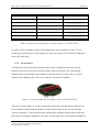
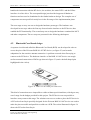
The Bluetooth Controlled Beetle
The “Bluetooth Controlled Beetle” was a project performed at Master level by two students at
Lunds Institute of Technology in November year 2000. The BT controlled Beetle (see figure
6) was a prototype used to show that the BT wireless technology and the Bluetooth Control
Card (BCC) designed in the project worked. [Brodin & Nilsson 2000]
De Montfort University
Faculty of Computing Sciences and Engineering
MSc Mechatronics 2001/2002
16
Andreas Eriksson
Master Thesis. “Bluetooth for mobile robots (communication units)”
2002-09-20
Figure 6. The Bluetooth controlled Beetle. [Brodin & Nilsson 2000]
The Beetle was in scale 1/10th and it was steered by a joystick. Figure 7 shows how the
control of the car was configured. The signals from the joystick were transmitted to the PC,
which then computed the control signals and transmitted them to the car. [Brodin & Nilsson
2000]
Figure 7. Control configuration for the Beetle. [Brodin & Nilsson 2000]
The system used Ericsson Bluetooth Application Tool Kits, which were interfaced to a PC on
one side. On the other side it was interfaced to the car and the joystick through the BCC,
which was a general circuit board (see figure 8 below) that enabled an interface to almost any
electrical device, which then gained the benefits of wireless communication via BT. [Brodin
& Nilsson 2000]
De Montfort University
Faculty of Computing Sciences and Engineering
MSc Mechatronics 2001/2002
17
Andreas Eriksson
Master Thesis. “Bluetooth for mobile robots (communication units)”
2002-09-20
Figure 8. Hardware solution of the BCC. [Brodin & Nilsson 2000]
The (BCC) consisted of an embedded BT solution enabling data communication using up to
the L2CAP layer in the BT protocol stack, the L2CAP layer is briefly described in appendix
A. The stack was embedded in a PIC16F876 microcontroller that also handled all the I/O: s of
the general control card. [Brodin & Nilsson 2000]
The Master Thesis just described has served as a good piece of literature for idea generation
to the design of the KBU, especially for the stack design according to the well documented
structure and code of the embedded software.
2.2.2
Radio Controlled Robot Car
The “Radio Controlled Robot Car” (see figure 9) was developed in a BSc Thesis paper made
by two Electrical Engineering students from the University of Karlskrona/Ronneby, which
was completed in July 2000. [Dijkstra & Martena 2000]
Figure 9. Radio Controlled Robot Car. [Dijkstra & Martena 2000]
De Montfort University
Faculty of Computing Sciences and Engineering
MSc Mechatronics 2001/2002
18
Andreas Eriksson
Master Thesis. “Bluetooth for mobile robots (communication units)”
2002-09-20
The objective of their project was to create a point-to-point connection between a Robot Car
and a PC both equipped with Bluetooth Starter Kits. The PC ran a program that sent steering
(acceleration/braking) information to the Robot Car, which received the data and controlled
its stepper motors accordingly. Two Ericsson Bluetooth Starter Kits were used as
communication devices (they can be viewed in figure 10). The host in the Robot Car was a
Digital Signal Processor (DSP) sitting on a development board. [Dijkstra & Martena 2000]
Figure 10. Architectural overview for the Robot Car. [Dijkstra & Martena 2000]
The design and operation of the BT point-to-point connection in this thesis were documented
very well and in high detail. The functionality of each protocol layer was described well and
shows the flow of data with precision. The use of a DSP card made this project less relevant
to the design of the KBU that used a microcontroller.
2.3
Wireless control of the Khepera platform
There have been several attempts in replacing the cable to communicate control commands
between the Khepera robot and the host computer. The vendor for the Khepera equipment (KTeam) offers one solution for wireless communication with the robots using radio. Another
solution found communicates via IR and both techniques were critically reviewed in this
section.
De Montfort University
Faculty of Computing Sciences and Engineering
MSc Mechatronics 2001/2002
19
Andreas Eriksson
Master Thesis. “Bluetooth for mobile robots (communication units)”
2.3.1
2002-09-20
Khepera Radio Turret
The Khepera radio turret together with the Khepera base station is the wireless option
available from K-Team to communicate between the host computer and the robots. A typical
configuration of the radio network is presented in figure 11 below.
Figure 11. Overview of the Khepera radio base and turret system. [K-Team 1999 b]
The radio network is composed of maximum 31 Khepera robots equipped with radio turrets
and by one radio base station connected to the host computer. Direct robot addressing, error
detection and correction are possible. The system also offers long-range inter-robot
communication, wireless monitoring of robot activities and ability to monitor collective
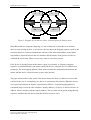
behaviour as new possibilities in autonomous robotics. [ANON 2002 a]
The radio channel is half duplex, which means that reception and transmission of data are
mutually exclusive. It operates at frequencies of 418 MHz or 433,920 MHz. The speed (real
throughput) of the radio is up to 9600bps depending on the size of the messages (4800bps
typical) and the range is 10 meters. [K-Team 1999 b]
The network is configured so the default state of the radio turret (see figure 12) is reception.
As soon as data has to be transmitted, the state changes and the data are transmitted. The data
transmitted on the radio channel is encapsulated in packets and the maximum length of data in
a packet is 16 bytes. [K-Team 1999 b]
According to Nicklas Bergfeldt (the initiator to this MSc project) this existing radio system
was insufficient and barely handled communication with one robot at a time. This was mainly
De Montfort University
Faculty of Computing Sciences and Engineering
MSc Mechatronics 2001/2002
20
Andreas Eriksson
Master Thesis. “Bluetooth for mobile robots (communication units)”
2002-09-20
due to the slow radio media, but it was also caused by the limit of 16-byte information in one
data packet. The information usually sent in the Khepera system is longer than 16 byte and
needs to be sent in several packets, which contributes to a slow system. The turret presented
in figure 12 below is 55*55*15 mm and it contains a Motorola M68331 microcontroller that
handles both the radio and K-bus interface. [ANON 2002 a]
Figure 12. Khepera radio turret. [ANON 2002 a]
The Khepera radio turret has been useful as reference when designing the KBU. The most of
the hardware differs but the purpose of the both systems are the same. When design
difficulties occurred it was nice to have another solution to look at that already had solved
those problems. The documentation of the Khepera radio turret was not as good as I was
hoping.
2.3.2
Communication with Khepera robots over a CAN infrared network
The CAN infrared network was designed in a Thesis produced at Master level in Paderborn
University, Germany. The Thesis report was in German, which made it very hard to
understand some parts. It described a very fascinating project and that was the reason to
include it in the literature review.
A wireless communication system for the Khepera robots was developed and built with the
use of a CAN (Controller Area Network) fieldbus system and IR for wireless data
transmission. It included communication between single robots as well as between a robot and
an external host computer. A complete concept for communication was designed (see figure
De Montfort University
Faculty of Computing Sciences and Engineering
MSc Mechatronics 2001/2002
21
Andreas Eriksson
Master Thesis. “Bluetooth for mobile robots (communication units)”
2002-09-20
13). The main focus was on low power consumption and a safe communication link.
[Odenbach 1999]
Figure 13. Overview of the CAN infrared network. [Odenbach 1999]
The communication system contained an extension for the robot (see figure 14) and a repeater
with additional master functions, based on the fieldbus system CAN with infrared
transceivers. The System enabled wireless communication between a host computer and a
single robot at 9600 baud (serial link), but also data exchange between robots (k-bus). The
used fieldbus system CAN introduced error control, bus arbitration and addressing, at a
transmission rate of 100 kbps. [Löffler et al 1999]
Figure 14. Top view of the CAN infrared turret. [Odenbach 1999]
De Montfort University
Faculty of Computing Sciences and Engineering
MSc Mechatronics 2001/2002
22
Andreas Eriksson
Master Thesis. “Bluetooth for mobile robots (communication units)”
2002-09-20
The hardware used in the design is pointed out in figur 14. The components were all surface
mounted in order to save space on the small circuit board. The design of the KBU struggled
with the same size boundaries. The project just described was used to give inspiration to the
hardware design of the Khepera system developed.
2.4
Embedded Bluetooth research
There were a long row of relevant research projects made in the area of embedded BT. The
aim of those projects may not have anything to do with wireless control of mobile robotics but
they definitely contributed to the success of this project. This part discribes two of the projects
made in embedded Bluetooth starting with the PlayMobile project and ending with the
BlueNurse project.
2.4.1
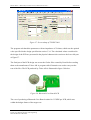
PlayMobile
The “PlayMobile” project was a project at Master level performed by two students at Lunds
Institute of Technology in November year 2000. The aim of the project was to investigate
mobile gaming over GSM- and BT networks, by developing a concept prototype, connecting
a Gameboy to a mobile phone over BT. [Gunée & Iranpour 2000]
There were basically two ways of connecting a BT device (or any other extra hardware) to a
Gameboy, first through the serial port, and second through the cartridge port. The project
produced both of the solutions. The cartridge port solution (see left part of figure 15) had the
best performance but required more hardware, was more complicated and expensive. The
serial interface solution (see right part of figure 15) was easier to implement and required less
hardware. The serial interface solution was not sufficient for the PlayMobile project but it had
great relevance to the KBU. [Gunée & Iranpour 2000]
De Montfort University
Faculty of Computing Sciences and Engineering
MSc Mechatronics 2001/2002
23
Andreas Eriksson
Master Thesis. “Bluetooth for mobile robots (communication units)”
2002-09-20
Figure 15. PlayMobile solutions. [Gunée & Iranpour 2000]
Both solutions incorporated Ericsson BT hardware and an AVR AT90S8515 microcontroller
from Atmel to run the BT stack. The block schematic of the serial interface solution is
presented in figure 16. The similarities to figure 3 describing the KBU were of great extent.
Figure 16. Block schematic of the PlayMobile serial solution. [Gunée & Iranpour 2000]
This report contained well-documented information of the two implementations and the
source code for the embedded stack. The stack was adapted to this special application and
could not be used without a massive effort in code reengineering.
2.4.2
The BlueNurse Wireless Link
The “BlueNurse” project was performed by three students at Bachelor level in the School of
Information Technology And Electrical Engineering at the University of Queensland,
Australia in October year 2001. The project aimed to remotely monitor and log patient’s vital
signs. The project was divided in three different parts (see figure 17) where one of them was
looking at the design of a BT wireless link for the Blue Nurse system. [Naveenan 2001]
De Montfort University
Faculty of Computing Sciences and Engineering
MSc Mechatronics 2001/2002
24
Andreas Eriksson
Master Thesis. “Bluetooth for mobile robots (communication units)”
2002-09-20
Figure 17. BlueNurse Block diagram. [Naveenan 2001]
Two host protocols: the Host Controller Interface (HCI) and the Logical Link and Adaptation
Protocol (L2CAP), were implemented in software creating the BT host stack. This stack was
ported both to an Atmel AT90S8535 microcontroller and the Intel x86 series of processors.
The ability to run the same BT host stack on different hardware was achieved by using the
ANSI C language. The wireless link was created using the host software protocols with an
Ericsson Bluetooth Application Tool Kit (same kit used in the Bluetooth Controlled Beetle,
see figure 8). The schematics of the Bluetooth wireless link with host stack and BT device are
shown in figure 18. [Naveenan 2001]
Figure 18. Schematics of the BlueNurse wireless link. [Naveenan 2001]
De Montfort University
Faculty of Computing Sciences and Engineering
MSc Mechatronics 2001/2002
25
Andreas Eriksson
Master Thesis. “Bluetooth for mobile robots (communication units)”
2002-09-20
The result of the implementation were summarised as follows. The ad-hoc nature of BT was
demonstrated with dynamic connection establishment and release. Asynchronous data transfer
with 1 Kbytes data packets was also achieved to demonstrate the use of L2CAP segmentation
and reassemble. Packet routing and dynamic network formation could not be implemented as
the BT devices used only supported point-to-point connections. [Naveenan 2001]
This Thesis explained the implementation of the BlueNurse wireless link well and especially
how the BT host stack was constructed. One drawback was that the ANSI C source code was
not available.
De Montfort University
Faculty of Computing Sciences and Engineering
MSc Mechatronics 2001/2002
26
Andreas Eriksson
Master Thesis. “Bluetooth for mobile robots (communication units)”
2002-09-20
3 Design specification
The design specification forms a “blueprint” from which the detailed design proposal was
formulated. The requirements were first specified to give input to form the specifications for
the different parts of the application, e.g. hardware and software.
3.1
Specification of requirements
The requirements applicable for the entire product design were specified in this chapter. The
requirements focused on the performance, environment, product target cost, size and weight.
3.1.1
General requirements
The following requirements was required to be met from the KBU:
•
Perform ten control loops every second in order to meet the requirements for real-time
control of the robots from the host computer. The specification of the control loop is
further described in section 3.2.
•
The units must work as a plug and play unit for the robots and contain a fulldeveloped interface to the robot.
•
The Khepera robot has quite low battery capacity and every extra module added to the
basic configuration increases the power consumption. The robot is equipped with
batteries with a capacity of 180mAh. This capacity allows the robot autonomy of
about 45 minutes in the basic configuration. According to these facts the power
consumption is 240mA in the basic configuration. The requirement was set to cause a
maximum reduction to the time by 15 minutes, which resulted in maximum power
consumption of approximately 100mA. [K-Team 1999 a]
•
The realistic target cost for one unit was set to approximately £200 (3000 SEK). It
only included the estimated material cost and not the production, development and
equipment costs. These costs did not affect the customer (the Computer Science
Department); hence they were paid by the Engineering Department at the University
of Skövde.
De Montfort University
Faculty of Computing Sciences and Engineering
MSc Mechatronics 2001/2002
27
Andreas Eriksson
Master Thesis. “Bluetooth for mobile robots (communication units)”
•
2002-09-20
The unit must contain hardware and software supporting an embedded solution for BT
communication with a base station.
3.1.2
Hardware requirements
The specific requirements for the hardware were as follows:
•
It should be a module to the Khepera robot whatever that meant in terms of restriction
in size (area and height) and connections to the robot. Further specifications are in the
section K-bus (3.3.1)and Circuit board (3.3.2) in the hardware specification part.
•
Robust constructions of the unit in order to manage normal use e.g. assemble and
disassemble.
•
Wiring specifications for the individual components must be followed in order to
minimise the amount of noise absorbed and inductance created in the wires.
•
The weight of the Bluetooth communication unit was under restrictions in order to not
reduce the power consumption and speed of the robots.
3.1.3
Software requirements
The software developed in this project consisted of a stack (a number of protocols) that
enabled the communication between the BT device and the robot. The stack was embedded in
a microcontroller to fit the application in terms of size and purpose. The specific requirements
applicable for the software were:
•
The software stack was to follow the BT standard v 1.1 in order to be fully compatible
with the RBS.
•
The software was forced to incorporate the Khepera turret protocol standard in order
to enable communication with the robot.
De Montfort University
Faculty of Computing Sciences and Engineering
MSc Mechatronics 2001/2002
28
Andreas Eriksson
Master Thesis. “Bluetooth for mobile robots (communication units)”
•
2002-09-20
The software had to be developed in a high level language like C in order to maintain
visibility of the code.
3.1.4
Link requirements
The requirements for the radio based communication link were:
•
Sufficient bit rate for the radio communication to give real-time control capability of
the Khepera robots.
•
The link had to enable the Khepera robots to operate in a network with at least 4
robots and a host computer via Bluetooth.
•
The robots were operating in an area of 3 x 3 meters that required a proper radio
communication within a distance of 5 meters in radius.
•
Techniques for safe radio communication had to be used to ensure a low rate of lost
data and disturbance absorbed from equipment in the environment.
3.2
Specification of the control loop
The specification of how the control loop for controlling a robot from the host computer was
discussed in order to give the overall specification of the system functionality. The existing
control architecture for the Khepera was adopted in this project in order to fully provide the
system with the control features that was originally designed. The loop used for control the
robots from the host computer followed the steps described in figure 19 below. The host
computer requests for the status of the eight Infra Red (IR) sensors that are used to describe
the environment the robot is operating in. The robot checked the values of the IR-sensors and
sends them to the host computer, which calculated the control parameters. The parameters
were then sent to the robot, which translated them into control commands for the motors that
drove the robot. The commands used were capital ‘N’ to request the status of the IR-sensors
and capital ‘D’ to send the motor speed parameters. The commands are more described in
section 3.4.2.
De Montfort University
Faculty of Computing Sciences and Engineering
MSc Mechatronics 2001/2002
29
Andreas Eriksson
Master Thesis. “Bluetooth for mobile robots (communication units)”
2002-09-20
Figure 19. Control loop for controlling a robot from the host computer.
3.3
Hardware specifications
The hardware specification described the design in terms of functional, mechanical and
electrical aspects for the individual parts.
3.3.1
K-bus
The interface to the K-bus consists of 57 pins, which placements and functions briefly are
illustrated in figure 20 below.
Figure 20. K-Bus overview.
De Montfort University
Faculty of Computing Sciences and Engineering
MSc Mechatronics 2001/2002
30
Andreas Eriksson
Master Thesis. “Bluetooth for mobile robots (communication units)”
2002-09-20
The bus enabled a local multi-microcontroller network, which was the recommended way to
realise performant extension units on Khepera. This allowed the connection of intelligent
units equipped with their own local microcontrollers. For this approach the control of these
units were realised by writing a dedicated software layer (on the local microcontrollers) to
realise the interface between Khepera and the different devices of the units. [K-Team 2001]
To design a unit supporting the multi-microcontroller network, a special 6-wire bus was used
to communicate. The PAI, SCK, F7, /CSCOM, MISO and MOSI pins briefly described in
table 1 below were used. The implementation of the network also required knowledge about
how to access the BIOS of the Khepera robots. [K-Team 2001]
The KBU was considered to only perform communication with the host computer and the
existing way of doing this was roughly to connect the TxD (pin 53) and RxD (pin54) to the
comport of the host computer. These signals were already spread on the K-Bus and available
for the KBU. There was no need to communicate over the multi-microcontroller network and
share the 6-wire bus with the other turrets when the UART communication was free to use.
The signals of the power group (see table 1) are used for all kind of turrets to supply them
with power.
Table 1. Pin specification. (Redrawn from [3])
The electrical specifications for the K-bus in absolute maximum ratings (for one unit) are
presented in table 2. [K-Team 2001]
De Montfort University
Faculty of Computing Sciences and Engineering
MSc Mechatronics 2001/2002
31
Andreas Eriksson
Master Thesis. “Bluetooth for mobile robots (communication units)”
2002-09-20
Type
Value
Comment
Supply voltage (Vcc)
-0.5V to 6.5V
______________
Load on the power
100mA
______________
Load by signal (digital)
2 HC loads
______________
Load by signal (analog)
1mA
only on VRef output
DC output voltage (digital)
-0.5V to Vcc+0.5V
______________
DC output voltage (analog)
-0.2V to VRef+0.2V
______________
Table 2. Electrical specification for the K-bus interface. [K-Team 2001]
In order to allow a modular system with multiple units 45 bus signals out of the 57 were
needed to be spread, twelve of the signals were only used on the CPU board of the Khepera
robot. [K-Team 2001]
3.3.2 Circuit board
The Khepera robot is built up by modules and in order to support this structure certain
physical restrictions were present for the design of the circuit board. The robot and the
modules have a round shape with a diameter of 50 mm. Figure 21 below shows a typical
module for the Khepera robot; the one presented is a general I/O-module.
Figure 21. Typical module for the Khepera robot. [ANNON 2002 a]
The pins viewed in figure 21 are the connection to the K-bus. The placement of the pins on
the circuit board restricts the maximum area that could be used for the electrical design
solution. Appendix C shows the drawing containing the complete measurements of the bus
placement. According to appendix C the space on each side of the circuit board available for
De Montfort University
Faculty of Computing Sciences and Engineering
MSc Mechatronics 2001/2002
32
Andreas Eriksson
Master Thesis. “Bluetooth for mobile robots (communication units)”
2002-09-20
the design solution was approximately a square shaped area of 40*30 mm plus some
additional room near the edges. The physical design of the circuit board had one more
limitation and that was the height of the electrical solution. Figure 22 shows the main
constraint to ensure a good mechanical compatibility between all the modules.
Figure 22. Mechanical bus constraint. [K-Team 1999 a]
3.3.3
Wiring specifications
The wires was designed to follow the individual wiring specifications for each component.
The general specifications for the wiring considered while designing a product dealing with
fast data rates were:
•
Short: The length of the physical conductors had to be short in order to counteract
disturbances and noise added to the signals.
•
Separated: The conductors could not be placed to near each other due to electrical
disturbances caused from each other.
•
Built-in: The wiring should be printed on the circuit board in order to give a safe and
reliable design.
De Montfort University
Faculty of Computing Sciences and Engineering
MSc Mechatronics 2001/2002
33
Andreas Eriksson
Master Thesis. “Bluetooth for mobile robots (communication units)”
3.3.4
2002-09-20
Microcontroller
The microcontroller was the co-ordinating part of the design solution and was to possible the
integration of BT communication for the Khepera robots. Many of the requirements specified
in section 3.1 directly affected the design parameters for the microcontroller. The speed of the
microcontroller was crucial in order to correspond to the overall speed requirement of the
system. The speed was both depending on how fast instructions can be carried out and the
workload for the microcontroller. The tasks for the microcontroller was basically consisting of
interfacing both the K-bus and the BT device and also translate the information between the
two interfaces by using protocols that followed specific standards. The specification of the
software embedded in the microcontroller (dealing with the translation) is described in section
3.4.
One requirement was that the software should be written in a higher level programming
language than assembler in order to maintain visibility of the code. A compiler for a high
level language was therefore desired for the microcontroller. The Electronics Department at
the University of Skövde had experience and equipment for the Atmel 8-bit AVR
microprocessor series, which worked fine with a C-compiler.
The I/O specification for the microcontroller was divided into three parts:
1. Interface to the K-bus: This interface was specified in section 3.3.1 and consisted of
the two I/O’s to enable the UART communication between the KBU and the Khepera
robot. The K-bus did also provide the unit with the power supply (electrical
specification according to table 2).
2. Interface to the Bluetooth chip: The interface to the BT device restricted the type of
communication to three techniques UART, USB and PCM. Many microcontrollers
enables the functionality of an UART interface, which was used in this application.
The simplest UART communication interface using two I/O’s was used; see further
description in section 3.3.5.
3. Interface to status diodes, buttons and switches: Two diodes was used to display
the status of the MCU and one button was used to give reset functionality. Eight
De Montfort University
Faculty of Computing Sciences and Engineering
MSc Mechatronics 2001/2002
34
Andreas Eriksson
Master Thesis. “Bluetooth for mobile robots (communication units)”
2002-09-20
switches was used to perform certain settings for the KBU. These I/O’s had to be
considered during the design of the I/O interface.
The I/O requirements were summarised as eight inputs, two outputs and two 2-wire UART
ports. The size of the microcontroller was important in order to fit in the restricted space of
the circuit board. Typical measurement of a suitable microcontroller could be around 20*20
mm. The electrical specifications for a typical microcontroller are specified below.
•
Power Consumption varies depending on the clock frequency, running mode, voltage
and operating temperature. Desired value was < 5mA.
•
Operating Voltages was desired to be 3.3V, which was the same as the BT device.
3.3.5
Bluetooth device
The BT device that was used is presented in figure 23 below. It is a multi-point device from
Ericsson that suited this application well; it goes under the name ROK 101 007. The chip
includes a baseband processor, BT Radio, application and antenna interfaces and supporting
circuitry, together with low-level BT software. The device supports both voice and data
transmission. External communication is carried out using the device’s built-in full-speed
USB, UART or PCM interface. The chip is a power class 2 Bluetooth device, and is qualified
for version 1.1 of the Bluetooth specification. The dimensions of the device are 33x17x3 mm
and the asynchronous data channel can support maximal 723.2 kbps asymmetric (and still up
to 57.6 kbps in the return direction), or 433.9 kbps symmetric. [Ericsson 2001]
Figure 23. Bluetooth device. [Ericsson 2001]
De Montfort University
Faculty of Computing Sciences and Engineering
MSc Mechatronics 2001/2002
35
Andreas Eriksson
Master Thesis. “Bluetooth for mobile robots (communication units)”
2002-09-20
The UART interface was used to connect the device to the microcontroller. The UART
interface implemented on the chip was an industry standard 16C450 and supports baud rates
up to 460800 bits/s. Figure 24 shows a block diagram of the interfaces to the BT device. Only
two signals was used for the UART interface. TxD (B5) and RxD (A5) used for data flow.
The flow control signals RTS (A6) and CTS (B6) were not required for the simplest
application. A 128 byte FIFO buffer was associated with the UART of the ROK 101 007.
[Ericsson 2001]
Figure 24. Interfaces of the Bluetooth device. [Ericsson 2001]
Power consumption
The Bluetooth technology corresponds well to the requirement of low power consumption.
The technology was special designed for mobile applications, which requires low power
consumption. The Bluetooth chip can operate in different modes depending on the operation
performed. Table 3 specifies the power consumption for the different modes. [Ericsson 2001]
Table 3. Power consumption for ROK 101 007. [Ericsson 2001]
De Montfort University
Faculty of Computing Sciences and Engineering
MSc Mechatronics 2001/2002
36
Andreas Eriksson
Master Thesis. “Bluetooth for mobile robots (communication units)”
2002-09-20
3.3.6 Antenna
The design specifications applicable for the antenna in order to qualify as an antenna for the
BT device are discussed here. The quality and length of the conductor connecting the antenna
to the BT device was very important to consider in the design. The length of the conductor
should be kept short to counteract absorption of disturbances from external sources and also
to prevent from creating disturbances for the other components in the Khepera robot.
It was very important to keep the quality of the antenna conductor high. The output routing
was desired to be 50 ohm and the Voltage Standing Wave Ratio (VSWR) to 2:1 all the way to
the antenna, in order to maintain good radio performance according to the data sheet for the
BT device. [Ericsson 2001]
A VSWR of 2:1 gave in other words an allowable variation of the impedance between 25 and
100 ohms for the conductor connecting the BT device and the antenna together. This was
according to the following calculations, where the VSWR relationship for the allowed
impedance is presented in equation 1.
VSWR =
rˆc =
2 1 + rˆc
=
1 1 − rˆc
Equation 1
50 − zc
50 + zc
Equation 2
The value of r̂c is obtained from equation 1 as rˆc =
1
; this results in the two following values
3
for r̂c .
rˆc =
1
3
and
rˆc = −
1
3
Putting these values in equation 2 gave;
1 50 − zc
=
3 50 + zc
De Montfort University
Faculty of Computing Sciences and Engineering
MSc Mechatronics 2001/2002
1 50 − zc
− =
3 50 + zc
37
Andreas Eriksson
Master Thesis. “Bluetooth for mobile robots (communication units)”
2002-09-20
50 + zc = 150 − 3zc
50 + zc = −150 + 3zc
z c = 25Ω
zc = 100Ω
so the allowable impedance range was 25Ω < z c < 100Ω . Equation 1 and equation 2 were
taken from [Carr 1994].
3.3.7
Hardware functions
In order to come up with a hardware design proposal the requirements for the hardware were
transformed into functions for the design to support. The functions were also presented to give
an overall picture of the hardware functionality. The following eight bullet points specified
the detailed functions for the hardware design:
1. On/Off function: The possibility to shut off the entire KBU was introduced to give
the option of accessing the existing cord-based serial communication instead of the
radio-based solution provided by the KBU. The on/off function for the KBU resulted
in that the unit doesn’t need to be disassembled when it isn’t used. The disassembly
procedure is usually time consuming and can harm the hardware. The function adds
flexibility and preserves the hardware.
2. Voltage regulation function: The input voltage is somewhere between +4 and +6
Volts and the KBU requires an operation Voltage to be stabile at +3.3 Volts. The
function of regulating the voltage to suit the components used in the proposed design
were considered as a must.
3. Reset function: A manual controlled reset function was necessary to be specified in
order to enable a reset of the BT device and the MCU if an error occurs.
4. Interfacing the BT device function: One of the most important functions for the
KBU to perform was the Bluetooth radio communication. The function of interfacing
the BT device was specified to enable the use of the ROK 101 007 BT chip. The
function considered the interface to the antenna and the UART port.
De Montfort University
Faculty of Computing Sciences and Engineering
MSc Mechatronics 2001/2002
38
Andreas Eriksson
Master Thesis. “Bluetooth for mobile robots (communication units)”
2002-09-20
5. Show status function: The show status function was introduced to inform the user of
the KBU status. The idea was to display the status by the use of three status LED’s.
One green LED to indicate power on, one blue LED to indicate a Bluetooth
connection with the base station and one red LED to indicate an error.
6. K-Bus communication function: The communication between the Khepera robot and
the KBU was designed to work via a standard two-wire UART over the K-Bus. The
K-Bus Voltage levels for a logical zero was 0V and logical one +5V the MCU used
0V and +3.3V respectively. In order to support the communication the use of a line
driver were considered mandatory.
7. Choice of baud rate function: The Khepera robot itself gave the opportunity to
alternate the baud rate of the UART communication. The choice of baud rate function
was introduced to give the same functionality to the KBU. The user is then able to
interact with the KBU and set the baud rate for the UART communication with the Kbus.
8. Choice of robot ID number function: This function was specified to possible the
user to interact with the KBU and to set the robot ID number for the BT
communication with the base station. The possibility of assigning an ID number for a
specific robot solved the problem of communicating with several robots. This function
was unfortunately not fully developed in the time available for this project but it was
considered while forming the conceptual design of the hardware.
The functions just specified were used to form the hardware concept described in section 4.1.
De Montfort University
Faculty of Computing Sciences and Engineering
MSc Mechatronics 2001/2002
39
Andreas Eriksson
Master Thesis. “Bluetooth for mobile robots (communication units)”
3.4
2002-09-20
Software specifications
The software designed in this project was considered to run on a microcontroller, which
limited the complexity and functionality added to the software. The code was developed in
ANSI C environment and then downloaded to the microcontroller. Two direct benefits of
using C in software design for embedded systems are according to [Zurell 2000]. The first
benefit is that the level of details won’t be overwhelming. The abstraction level of the code is
higher, which will keep the programmer from “miring down in opcode sequences and silicon
debugs”. The quotation taken from [Zurell 2000] clearly emphasise the result of good
visibility of the program code written in C compared to lower level languages. The second
benefit is that a portable program is created. The C-code is pretty much generic and can be
downloaded to any piece of hardware while the assembler code is very hardware specific.
[Zurell 2000]
The software designed in this project dealt with the protocols required for both
communication with the BT device and the Khepera robot. Figure 25 describes the general
design of the software. The general approach of designing a BT application is to keep the
functionality’s of the BT protocol stack separated from the other parts and to access the BT
stack through an Application Programmable Interface (API). The general approach was used
when designing the software for this project. The application to run in this case was the
translation into Khepera protocols. The individual parts are further described in the following
sections.
Bluetooth
protocol
stack
API
Khepera
protocol
Figure 25. General software design.
3.4.1
Bluetooth protocol stack
The BT protocol stack consisted a set of related software functions, each performing one of
the tasks required to accomplish communication between two or more devices. The various
protocol layers within the BT protocol stack worked together to ensure that data was
transmitted reliably from one BT device to another BT device. The different protocols of the
stack are briefly described in appendix A. [Asahania 2002]
De Montfort University
Faculty of Computing Sciences and Engineering
MSc Mechatronics 2001/2002
40
Andreas Eriksson
Master Thesis. “Bluetooth for mobile robots (communication units)”
2002-09-20
The Bluetooth stack was designed to be embedded in the microcontroller and therefore
simplified as much as possible in order to not put to much workload on the microcontroller.
The lowest amount of layers from the stack required to fulfil the task should be used. The
stack was only designed to be a prototype of the BT specification v. 1.1 but still complete
enough in order to be used properly with the BT hardware.
The lowest layer of the BT stack to be implemented in the BT host (the MCU) was the Host
Controller Interface (HCI) layer, which is pictured in figure 26 below. The physical bus driver
could be excluded in this case, because the UART port functionality was already implemented
in the MCU. The HCI provided an uniform interface method of accessing the BT hardware
capabilities. The stack development for the KBU was based on the HCI layer, which was the
only layer used here.
Figure 26. Lower layers of the Bluetooth software stack. [Bluetooth SIG 2001]
Another thing taken into consideration while the BT stack was designing was the technique
used to communicate between the MCU and the BT device. In this case the UART ports was
used and the BT standard specified this as the HCI UART Transport Layer. The objective of
the HCI UART Transport Layer was to make it possible to use the Bluetooth HCI over a
De Montfort University
Faculty of Computing Sciences and Engineering
MSc Mechatronics 2001/2002
41
Andreas Eriksson
Master Thesis. “Bluetooth for mobile robots (communication units)”
2002-09-20
serial interface between two UART’s on the same PCB (see figure 27). The HCI UART
Transport Layer assumed that the UART communication was free from line errors. [Bluetooth
SIG 2001]
Figure 27. HCI UART transport layer. [Bluetooth SIG 2001]
There were four kinds of HCI packets that could be sent via the UART Transport Layer. HCI
did not provide the ability to differentiate the four HCI packet types without a HCI packet
indicator sent immediately before the HCI packet. The four HCI packets were:
1. HCI Command Packet with packet indicator 0x01. The HCI command packets were
used to send commands that set the functionality of the BT device. They could only be
sent to the BT device. [Bluetooth SIG 2001]
2. HCI ACL Data Packet with packet indicator 0x02. The ACL data packets carried
data information and they could be sent in both directions. [Bluetooth SIG 2001] A
more detailed specification of the data packets used in this application is presented in
section 3.5.
3. HCI SCO Data Packet with packet indicator 0x03. Could be sent in both directions,
carries voice information and were not used here. [Bluetooth SIG 2001]
4. HCI Event Packet with packet indicator 0x04. Could only be sent from the BT device
and were used to indicate status and actions of the BT device. [Bluetooth SIG 2001]
There was no claim to exactly follow the standard and certificate the KBU as a Bluetooth
product by the Bluetooth Qualification Review Group due to the lack of time for this Master
Thesis. There is a lot of information available about the Bluetooth specification v. 1.1 in
[Bluetooth SIG 2001].
De Montfort University
Faculty of Computing Sciences and Engineering
MSc Mechatronics 2001/2002
42
Andreas Eriksson
Master Thesis. “Bluetooth for mobile robots (communication units)”
2002-09-20
There are a few free stacks available on the Internet, which are written for different computer
platforms, but there was no stack available for implementation in this specific embedded
system. This project developed a stack to suit this specific application. The stack developed in
the Bluetooth Controlled Beetle project (see section 2.2.1) was used as reference.
3.4.2
Khepera protocol
The software design included interaction with the Khepera robot. The information sent
between the host computer and a robot consisted of control commands and the format of the
control commands had to be respected when the software was designed. The communication
with the Khepera robot was made by sending and receiving messages consisting of ASCII
characters. Every interaction between the host computer and a Khepera was composed by: [KTeam 1999 a]
•
A command, beginning with one ASCII capital letters and followed, if necessary, by
numerical or literal parameters separated by a comma and terminated by a carriage
return or a line feed, sent by the host computer to the Khepera robot. [K-Team 1999 a]
•
A response, beginning with the same ASCII letter as the command but in lower-case
and followed, if necessary, by numerical or literal parameters separated by a comma
and terminated by a carriage return and a line feed, sent by the Khepera to the host
computer. [K-Team 1999 a]
Figure 28 below illustrates the format specification of a typical control command for the
Khepera. When the control command capital ‘E’ was sent from the host computer to the
robot, the effect was that the instantaneous speed of the two motors were read and responded.
The total number of control commands are 18.[K-Team 1999 a]
Figure 28. Format specification of a Khepera control command. [K-Team 1999 a]
De Montfort University
Faculty of Computing Sciences and Engineering
MSc Mechatronics 2001/2002
43
Andreas Eriksson
Master Thesis. “Bluetooth for mobile robots (communication units)”
2002-09-20
During all communication the host computer played the role of master and the Khepera the
role of slave. The master initiated all communication. [K-Team 1999 a]
3.4.3
Application Programmable Interface
The Application Programmable Interface (API) was the specific interface between the BT
protocol stack and the Khepera protocols. The task for the API in this software was to perform
the translation of the data passing between the two types of protocols.
3.4.4
Software structure
The microcontroller used were interrupt driven and raised different status flags depending on
the interrupt type. The software was designed to use the different status flags in order to keep
track of internal and external actions. The software structure was of multi-file nature and
consisted of several files compiled together. An example of a multi-file structure is illustrated
in figure 29. The header file contained global variable and function declarations to give the
rest of the files access to them. The other files had different functionality’s and provided each
other with hardware independent services.
Figure 29. Example of a multi-file software structure. [Brodin & Nilsson 2000]
3.4.5
Software functions
The main task for the software to handle can briefly be described as: listen for received data
on two UART ports one connected to the BT device and one connected to the Khepera robot.
The message received on one of the UART ports was translated and transmitted on the other
UART port. The main task was broken down and considered together with the other tasks for
De Montfort University
Faculty of Computing Sciences and Engineering
MSc Mechatronics 2001/2002
44
Andreas Eriksson
Master Thesis. “Bluetooth for mobile robots (communication units)”
2002-09-20
the MCU to carry out e.g. the initialisation procedure, to form the functions required for the
software to support.
1. Initialisation function: All necessary initialisation procedures for both the MCU and
the BT device had to be supported.
2. Translation function: The translation function was identified to perform two
translations; one translating BT information into Khepera commands and another
performing the opposite translation. The translations were performed every time a
command was sent between the RBS and the Khepera robots and they had to be
carried out as fast as possible to keep the delay caused as small as possible.
3. Interrupt function: The interrupts caused by interactions from external actions such
as UART Rx interrupts had to be supported. The Bi-directional communication over
the two UART ports was designed to be interrupt driven in order to work as fast and
effective as possible.
4. Display status function: The software was designed to display the different statuses
the MCU could enter to inform the user of what was going on in the MCU. A blue
LED was turned on if a BT connection between two devices were noticed and a red
LED flashed when an error occurred.
3.5
Specification of data packets
All information sent over a Bluetooth channel was presented as packets. The specification for
the data packets used in this design had to follow both the Bluetooth and the Khepera
specification. The Bluetooth specification divides the ACL data packets in two major parts, a
header and the payload (see figure 30).
LSByte
Header 9 Bytes
MSByte
Payload max utilysing 132 Bytes
Figure 30. The two major parts of an ACL data packet.
De Montfort University
Faculty of Computing Sciences and Engineering
MSc Mechatronics 2001/2002
45
Andreas Eriksson
Master Thesis. “Bluetooth for mobile robots (communication units)”
2002-09-20
The information sent to the BT device over the HCI UART transport layer were sent in little
Endian style, which implies that the LSByte were sent first. Data fields bigger than one Byte
were also sent LSByte first. The packet header consisted of nine Bytes; figure 31 below
describes the contents of the header in greater detail.
Byte 0
Byte 1
Packet type
Byte 2
Connection handler PB
Byte 5
Byte 6
Byte 3
BC
Byte 7
L2CAP data length
Byte 4
Total data length
Byte 8
L2CAP CID
Figure 31. Packet header.
The different parts of the header are briefly commented below:
•
Packet type: The four types of packets are already described in section 3.4.1 and the
packet indicator for the ACL data packet was 0x02.
•
Connection handler: Is a unique number identifying the BT channel between two BT
devices. The data field is twelve bits long.
•
Packet Boundary flag (PB): The field was two bits long and was used to define if the
packet was the first out of several packets. The software designed here did not support
splitting data in multiple L2CAP packets. The data field was always set to 10.
Value
00
01
10
11
•
Parameter description
Reserved for future use
Continuing Fragmant Package of higher layer
message
First package of an higher layer message (i.e
start of an L2CAP package)
Reserved for future use.
Broad Cast flag (BC): The field was two bits long and defined to whom the packet
was sent.
De Montfort University
Faculty of Computing Sciences and Engineering
MSc Mechatronics 2001/2002
46
Andreas Eriksson
Master Thesis. “Bluetooth for mobile robots (communication units)”
Value
00
01
10
11
•
2002-09-20
Parameter description
No broadcast only point to point connection
Active broadcast. Sent to all active slaves.
Piconet broadcast. Sent to all slaves including
them in "Park mode".
Reserved for future use.
Total data length: The total number of Bytes including the L2CAP data length and
CID fields.
•
L2CAP data length: The total length of the payload specified in Bytes.
•
L2CAP CID: The field specified the Channel IDentifier (CID) for the channel.
The payload consisted of the data sent in the packet. The length of the data could vary
between 0 - 2745 bits, which allowed a big variety of data to be sent. [Björnsson 2001] The
Khepera specification did set the requirement for how the data should look like in the payload
area of a data packet. The specification of the Khepera commands were described in section
3.4.2. The longest Khepera command used had the length of 132 Bytes, which was the
maximum payload length utilised.
3.6
Tool specification
The main tools that was used during the design were:
•
ICCAVR C compiler: This C compiler was used for the development of the code in
the embedded software. The compiler is from ImageCraft and available as 30 days full
demo version on http://www.imagecraft.com/software/. The compiler is suitable for a
big range of microcontrollers.
•
Pony Prog: This serial device-programming tool was used for downloading of the
code to the MCU. The program is a freeware and available on
http://www.LancOS.com.
De Montfort University
Faculty of Computing Sciences and Engineering
MSc Mechatronics 2001/2002
47
Andreas Eriksson
Master Thesis. “Bluetooth for mobile robots (communication units)”
•
2002-09-20
Protel 99 SE: This PCB design and schematic tool was used for the layout and wiring
design of the circuit board. The software is available as 30 days full demo version on
http://www.protel.com/software/ where more information of the tool from Altium is
available.
•
TXLine 2001: Is a calculation program for calculating conductor parameters. This
program was used for calculations of the conductor between the BT device and the
antenna.
De Montfort University
Faculty of Computing Sciences and Engineering
MSc Mechatronics 2001/2002
48
Andreas Eriksson
Master Thesis. “Bluetooth for mobile robots (communication units)”
2002-09-20
4 Hardware implementation
The implementation part of the design proposal was divided into two main parts separating
the hardware and software implementations. The concept considered during the hardware
design was to follow the requirements specified in chapter 3.1. An important issue considered
during the hardware implementation was to design a unit as unnoticeable and transparent as
possible in the communication chain, which doesn’t influence the overall function of the
Khepera robot. The implementation started with a description of the design concept
identifying the hardware to support the functions specified in section 3.3.7. The concept was
then used to form the different hardware prototypes.
4.1
Conceptual design
The first step in the hardware concept design was to identify the main components and to
specify how they interact with each other and the external interfaces. Figure 32 below show
the hardware concept developed with consideration of the functions described in section 3.3.7.
Figure 32. Hardware concept.
The on/off button was designed to turn on or off the power supply to the entire KBU. The
voltage regulator then transferred the voltage level to +3.3V; used to supply all components.
The reset button was then connected to trig the reset pins on both the BT device and the
MCU. The MCU was designed to be the co-ordinating component of the concept. The MCU
De Montfort University
Faculty of Computing Sciences and Engineering
MSc Mechatronics 2001/2002
49
Andreas Eriksson
Master Thesis. “Bluetooth for mobile robots (communication units)”
2002-09-20
handles the interaction with the BT device, the switches, the status LED’s and the K-Bus
interface via a line driver. The conceptual design just described supports all hardware
functions and was used as foundation for the further hardware design. The complete set of
components was not specified exactly here in the first stage of the implementation phase.
The next stage to carry out was to design the hardware prototypes. The hardware was
developed in two steps where the first step focused on the interface to the BT device, thus
enabled the BT functionality. The second step was to design the hardware contained the MCU
and other components. The two steps are presented in the following subchapters.
4.2
Bluetooth Core Board design
A separate circuit board called the Bluetooth Core Board (BCB) was developed in order to
access the pins of the Ericsson ROK 101 007 BT device (see figure 23) and to make
adaptations for the sensitive antenna connection. A problem occurred when first trying to
connect to the BT device. The hardware interface of the ROK 101 007 device was trough
surface mounted connections of BGA type shown in figure 33 (notice the ball shaped pins
highlighted in the circles).
Figure 33. ROK 101 007 BGA pin connection.
This kind of connections were impossible to solder without special machines, which goes way
out of range for the budget provided for this project. The BT device was not possible to
interface at any extent at this stage. The solution was to use a socket to place the BT device in.
A BT socket from Suyin specially designed for the Ericsson ROK 101 007 device was used to
make the pins accessible and possible to solder on a PCB. The socket illustrated in figure 34
shows the BT socket from Suyin.
De Montfort University
Faculty of Computing Sciences and Engineering
MSc Mechatronics 2001/2002
50
Andreas Eriksson
Master Thesis. “Bluetooth for mobile robots (communication units)”
2002-09-20
Figure 34. Suyin BT socket.
The next difficulty was to solder the tiny pins on the socket distributing the connections to the
BT device. In order to solder the pins a special designed Printed Circuit Board (PCB) was
designed and produced. The procedure of producing the PCB is described in the next
subchapter. The pins of the socket were so tiny that a microscope and a really thin tip on the
soldering-iron was necessary to use.
The PCB was designed to also incorporate the antenna, the conductor connecting the antenna
to the BT device and 20 universal connector pins distributing the interface to the BT device.
The antenna used was a Swivel antenna from GigaAnt called Titanis (see figure 35 below)
with the following antenna features; placed on the PCB with a standard SMA connector; total
length 61.4mm, width 20mm, depth 18.4mm and rotating top.
Figure 35. Titanis Swivel Bluetooth antenna.
The choice of this specific antenna between others was due to the ease of connecting it to the
PCB by a simple SMA connector. A much smaller antenna can be used in future
improvements of the hardware design.
De Montfort University
Faculty of Computing Sciences and Engineering
MSc Mechatronics 2001/2002
51
Andreas Eriksson
Master Thesis. “Bluetooth for mobile robots (communication units)”
2002-09-20
The final design of the BCB with the socket, BT device, SMA connector, antenna and the
universal pins are illustrated in figure 36 below. The schematics describing the correlation
between the components are presented in appendix D.
Figure 36. Bluetooth Core Board.
4.2.1
Producing the Printed Circuit Board
The PCB of the Bluetooth Core Board (see figure 38) was produced with good adaptation of
the antenna conductor and it also distributed all connections to the BT device necessary (for
this project) through standard pins easy to use for prototypes. The design process of the PCB
was started by making the schematic drawing (see appendix D) in Protel then the PCB layout
was produced also in Protel. The shape and layout of the PCB was adapted to fit in the
Khepera structure.
The material used in the PCB was GaAs, which is preferable for signals in the Mega Hertz
range. The Microstrip connecting the antenna output of the BT device to the antenna was of
very high importance to succeed with a good radio communication. The program TXLINE
2001 was used to perform the calculations of the Microstrip in this design. The screen dump
of the calculation performed in TXLINE is presented in figure 37 below.
De Montfort University
Faculty of Computing Sciences and Engineering
MSc Mechatronics 2001/2002
52
Andreas Eriksson
Master Thesis. “Bluetooth for mobile robots (communication units)”
2002-09-20
Figure 37. Screen dump of TXLINE 2001.
The program calculated the parameters with an impedance of 50 ohms, which was the optimal
value specified in the design specification section 3.3.6. The calculated values considered in
the design of the PCB are presented in the physical characteristic section to the lower left part
of figure 37.
The final part of the PCB design was to test the Gerber files created by Protel before sending
them to the manufacturer Teltex AB. A program called Cantastic was used to carry out the
test of the files. The PCB produced by Teltex AB is illustrated in figure 38 below.
Figure 38. Bluetooth Core Board PCB.
The cost of producing a Bluetooth Core Board resulted in 335 SEK per PCB, which was
within the budget frames of the target cost.
De Montfort University
Faculty of Computing Sciences and Engineering
MSc Mechatronics 2001/2002
53
Andreas Eriksson
Master Thesis. “Bluetooth for mobile robots (communication units)”
4.2.2
2002-09-20
Verification of the Bluetooth Core Board
The functionality and performance of the BCB design was evaluated by producing two PC
dongle prototypes see figure 39 below. The dongles are called Radio Base Station (RBS)
because one of them was used in the continuos development of the base station in the other
part of this project. The RBS was equipped with a voltage regulator, a Maxim RS-232 line
driver, a DB-9 connector (female) and the special connectors to interface the BCB.
Figure 39. Radio Base Station.
The two dongles were connected to PC: s running a simple program called SimpleConnectC;
based on an “of the shelf” BT stack called the C-stack (freely available on www.cstack.com).
The benefit of using an already developed program based on an existing stack was the
certainty of a properly working software. If any errors are noticed it is very likely caused by
the hardware.
Figure 40. Interface of SimpleConnectC.
De Montfort University
Faculty of Computing Sciences and Engineering
MSc Mechatronics 2001/2002
54
Andreas Eriksson
Master Thesis. “Bluetooth for mobile robots (communication units)”
2002-09-20
Figure 40 above shows the interface of the SimpleConnectC program. The functionality of
this program was to initiate the BT device by pressing the “Start” button, search for other BT
devices by pressing the “Search for Bluetooth Devices” button and to connect to a chosen BT
device by pressing the “Open Connection” button.
The evaluation of the hardware by using this program showed that the BCB worked properly
in fact all functions of the SimpleConnectC program worked perfectly. The functionality of
the BCB was then considered verified.
4.3
Khepera Bluetooth Unit design
The second board designed was the Khepera Bluetooth Unit incorporating the MCU and the
rest of the parts described in the hardware concept. The prototype was developed in large
scale on a standard Wiro-Board to make it easier during the development. It was easy to do
measurements and corrections on the design. The first components attached were the voltage
regulator circuitry used to transform the input voltage to a stabile level of +3.3V. The voltage
regulator was built up using a standard linear regulator and a couple of resistors performing
voltage division.
After a reliable supply voltage level was obtained the RS-232 line driver was implemented.
The line driver was used to convert the voltage levels on the UART communication with the
K-Bus and also to facilitate communication with a standard PC comport. The prototype used a
Maxim transceiver called MAX3232CPE that has two receiver and two transmitter channels.
The component used required four 100nF capacitors.
The MCU was the next component to implement. An Atmel 8-bit AVR RISC (Reduced
Instruction Set Computer) of type ATMega 128L was used in this design proposal. The
ATMega 128L MCU fulfilled all the requirements specified in the design specification. The
MCU is small and only available in a PQFP (Plastic Quadrate Flat Package). It supports
double UART interfaces and has five full eight-pin I/O ports. It can be re-programmable at
any time. It has sufficient memory space, low power consumption and runs on +3.3V.
De Montfort University
Faculty of Computing Sciences and Engineering
MSc Mechatronics 2001/2002
55
Andreas Eriksson
Master Thesis. “Bluetooth for mobile robots (communication units)”
2002-09-20
The MCU was implemented with a 7.3728 MHz crystal oscillator, which was optimal to give
as low deviation for the UART baud rates as possible. When using the maximum crystal value
for the MCU at 8 MHz, the deviation is up to 7.8% at 115.2 kbps caused by dividing the baud
rate with respect of the frequency.
A problem occurred when trying to access the 64 pins of the MCU, which only were
separated with 0.8 mm. It was not possible to solder the MCU directly on the Wiro-Board so
the only option was to produce a self made socket holding the MCU. It was quite tricky to
solder all 64 pins of the MCU, the crystal and several capacitors onto the limited space
available on the self made socket. This required microscope and very fine soldering
equipment. The pins of the MCU were distributed to universal pins fitting on the Wiro-Board.
The final design of the socket with the components soldered is illustrated figure 41 below.
Figure 41. Microcontroller socket.
Two prototypes were designed in order to possible the development of multi-robot network.
The first prototype is illustrated in figure 42 and not all hardware such as the eight-bit DIP
Switch and the status LED’s were included. The figure points out the different parts on the
prototype.
De Montfort University
Faculty of Computing Sciences and Engineering
MSc Mechatronics 2001/2002
56
Andreas Eriksson
Master Thesis. “Bluetooth for mobile robots (communication units)”
2002-09-20
Figure 42. First prototype of the Khepera Bluetooth Unit.
The work continued and a second prototype was developed, which is illustrated in the left part
of figure 43 below. The knowledge obtained from developing the first prototype was used to
reduce the space required for the design. The approach of developing the second prototype
was slightly different. The second prototype was developed to be modular and to serve in two
purposes; first as a RBS and then as a KBU. The design was divided on two small WiroBoards where one of them contained the RBS functionality and the other the added
components to form the entire KBU. When the latter part was removed and the cable was
connected as in the right part of figure 43 the prototype was a simple PC dongle.
Figure 43. Second prototype of the Khepera Bluetooth Unit.
De Montfort University
Faculty of Computing Sciences and Engineering
MSc Mechatronics 2001/2002
57
Andreas Eriksson
Master Thesis. “Bluetooth for mobile robots (communication units)”
2002-09-20
The second prototype included all the parts from the conceptual design, the status LED’s and
the Switch were added. The KBU was not produced in PCB format and the prototypes were
the hardware developed within the time available for this project. A good start on the PCB
design was performed and further described in the next section.
4.3.1
Producing the Printed Circuit Board
The work with producing the PCB for the Khepera Bluetooth Unit started with creating the
schematic drawing of the proposed design in Protel; the schematic is appended in appendix D.
Not all of the components used for the prototype solution were suitable to fit the layout and
size constraints for the PCB solution. In order to fit in the size available on the PCB, surface
mounted components were considered mandatory. The surface mounted components
corresponding to the components used in the prototypes were chosen in most of the cases.
When improvements were possible to perform; other components were chosen.
The prototype used a Maxim transceiver called MAX3232CPE, which is large, has relatively
high power consumption and supports unnecessarily many receiver and transmitter channels.
The final design proposal used a single receiver called MAX3182 instead, which is very
small, low power consuming and only supporting one receiver channel connected to the Rx
line from the K-Bus due to the different logical levels. The next improvement was to change
the voltage regulator from a large standard circuit to a tiny LE33 ABD from ST
Microelectronics. Another improvement was to change the connector type to surface mounted
micro-connectors to save space.
The PCB layout proposal designed in Protel is illustrated in figure 44 below. The problem of
fitting all components inside the restricted area was a difficulty. All the conductors connecting
the pins together the same way specified by the schematic were not performed due to the lack
of time.
De Montfort University
Faculty of Computing Sciences and Engineering
MSc Mechatronics 2001/2002
58
Andreas Eriksson
Master Thesis. “Bluetooth for mobile robots (communication units)”
2002-09-20
Figure 44. Khepera Bluetooth Unit PCB layout proposal.
The PCB design work performed so far was considering a four layer PCB, three layers to
place the conductors on and one ground plane layer. The components could only be placed on
the two outer layers. The blue components in the figure were placed on the bottom layer and
the red components were placed on the top layer. The green circle was the physical constraint
caused by the size of the Khepera robot. The large yellow contour was the BCB placed on top
of the KBU. The components placed underneath the BCB was restricted in height. The design
required allot of components to be accessible for the user e.g. the on/off button, reset button,
serial line interface, the DIP Switch and the LED’s. The space available on the edges of the
layout was heavily restricted by the K-Bus. The layout presented in figure 44 is just a layout
suggestion.
The cost of producing a PCB like this was approximated to 500 SEK per PCB. The Bill Of
Materials, in other words the complete set of components used in the proposed design is
presented in appendix E. The total price for the design is according to the calculations in
appendix E summarised to 2045 SEK.
De Montfort University
Faculty of Computing Sciences and Engineering
MSc Mechatronics 2001/2002
59
Andreas Eriksson
Master Thesis. “Bluetooth for mobile robots (communication units)”
4.3.2
2002-09-20
Verification of the Khepera Bluetooth Unit
The prototype was verified to make sure that the hardware was performing well before
starting to develop any software solutions. The components were verified individually starting
with the voltage regulator that was tested by measuring the output voltage level with a Multimeter. An oscilloscope was also used to monitor the noise on the output from the voltage
regulator. Capacitors were added on both sides of the voltage regulator and the noise was
reduced to a reasonable level. The correct function of the MAX 3232CPE transceiver was
verified by performing a loop back test. The circuit was connected like figure 45 below
describes. The output and the input were short circuited to form a loop. The transceiver
transformed the logical levels correctly and returned the same information that was sent.
Figure 45. Test of the transceiver circuit.
The MCU was tested in order to verify the hardware implementation of the MCU on the
socket. An echo program was downloaded to the MCU, which simply returned whatever was
received on the UART. The test was carried out successfully. The BCB was already verified
so all the individual parts of the implementation worked fine.
De Montfort University
Faculty of Computing Sciences and Engineering
MSc Mechatronics 2001/2002
60
Andreas Eriksson
Master Thesis. “Bluetooth for mobile robots (communication units)”
2002-09-20
5 Software implementation
The software was developed in ANSI C program language using the ImageCraft development
environment (described more in section 3.6). The entire source code for the implementation is
appended in appendix F.
5.1
Conceptual design
The concept was to design a system supporting communication with several robots by the use
of piconets. The overall concept of having the base station as master and the robots as slaves;
supports the general idea of controlling several robots from a PC. The existing radio turret
system presented in part 2.3.1 used the same concept. The thought was then to keep the
software simple as possible and only use the necessary features in order to fulfil the
requirements. Each part of the communication chain between the PC and the Khepera robot
were causing a delay and therefore no extra features were added.
A BT piconet network support one master having up to seven independent radio connections
to other slave devices according to [Bray & Sturman 2001]. Each of them was identified with
a connection handler that was determined when the connection was created. In order to
identify which robot associated with each radio connection the robot ID can be set on the
KBU.
5.1.1
State diagram
After the functions were identified (see section 3.4.5) it was possible to form a state diagram
for the software. The software will express different states, moving between them after
processing external interactions or internal events. The diagram in figure 46 illustrates these
states and the stimuli that make it progress through them.
De Montfort University
Faculty of Computing Sciences and Engineering
MSc Mechatronics 2001/2002
61
Andreas Eriksson
Master Thesis. “Bluetooth for mobile robots (communication units)”
2002-09-20
Figure 46. Software state diagram.
The software starts in the initialisation mode, which initialise the hardware. The normal mode
enters after a connection is established with the RBS. The normal mode poll the command
received flag and the data received flag set by the UART interrupt routines. Translation mode
one translates the received Khepera command into an ACL data packet and transmits it to the
BT device. Translation mode two translates the incoming ACL data packet into a Khepera
command and transmits it to the Khepera robot. When any error occurs the error mode enters,
which flashes a red LED to indicate an error for the user. The only way to exit the error mode
is to make a hardware reset, which sets the software in the initialisation mode again.
5.1.2
Interrupts and polling
The interrupt and polling functionality of the software is illustrated in figure 47. The MCU
that was used was interrupt driven and sets different status flags depending on the interrupt
type. An interrupt subroutine was called for every generated interrupt. The subroutine
investigates the interrupts and trigs different status flags depending on the origin. The
software used two status flags to keep track of the external actions in form of received
Khepera commands or BT data packets. The main thread polled the status flags raised during
De Montfort University
Faculty of Computing Sciences and Engineering
MSc Mechatronics 2001/2002
62
Andreas Eriksson
Master Thesis. “Bluetooth for mobile robots (communication units)”
2002-09-20
an interrupt, such as receiving a data packet and then takes appropriate actions. The polling of
the status flags started after a BT connection was established with the RBS.
Figure 47. Interrupt and polling relationship.
The reason that the software was built to both support interrupts and polling was mainly to
make it as effective as possible. The software utilised the benefit of interrupt controlled
UART communication, which kept the application free while communicating. The
communication failed if an interrupt occurred during the execution of another interrupt
subroutine. The MCU prioritised all the interrupts and rejected the one with lowest priority,
which caused a failure and probably data losses. It was therefore very important to design the
interrupt routines as small as possible. Design the software to use polling kept the interrupt
routines smaller.
5.2
The embedded software
The embedded software was designed in a multi-file structure mentioned in section 3.4.4. The
final file structure for the proposed software design presented in figure 48 below reminds very
much of the multi-file structure described in figure 29. The file structure below consisted of
seven files performing different tasks. All the files are explained in the following sections.
De Montfort University
Faculty of Computing Sciences and Engineering
MSc Mechatronics 2001/2002
63
Andreas Eriksson
Master Thesis. “Bluetooth for mobile robots (communication units)”
2002-09-20
Figure 48. File structure.
5.2.1
Global functions and variables
The global variables and functions were defined as external in the “Global.h” header file.
When the header file was included in another file it was possible for that file to access the
global variables and functions. The header file was included in all the other files. The initial
values for the global variables were set in the “Global.c” file. Further information how this
was carried out can be seen in the code in appendix F.
5.2.2 Initialisation
The functions performing the initialisation of the entire design were gathered in one file
“Init.c”. The initialisation process was divided into three parts, which are illustrated by the
flowchart in figure 49 below.
De Montfort University
Faculty of Computing Sciences and Engineering
MSc Mechatronics 2001/2002
64
Andreas Eriksson
Master Thesis. “Bluetooth for mobile robots (communication units)”
2002-09-20
Start
Open and
initialise the
ports.
MCU
initialisation
Initialise timer
resources
Initialise
USART
resourses
Read robot ID
and baudrate on
PortC
Wrong
setting?
Yes
Error()
Read robot ID
and baudrate
No
Delay two
seconds
Call a HCI
command
function
Result
OK?
Initialisation of the
Bluetooth module
No
Error()
Yes
Initialisation
perfotmed
Figure 49. Flowchart of the initialisation process.
The initialisation procedure for the MCU, which was the first part can vary depending on
what parts of the MCU that are used. This application required initialisation of I/O ports,
timers and UART ports. The ports were initialised as input or output and their initial values
were set in the initialisation. The entire PortC was used as input to act on the settings of the
eight-bit DIP Switch. The Switch was used to set the robot ID and baud rate for the UART
communication with the Khepera robot. Pin zero and one on PortA were set as outputs to light
the blue and red LED. Two timers were used to cause delays. Timer0 to cause a one
millisecond long delay. Timer1 to a cause one second long delay. The timers overflow
interrupts were used to notice when the specified time was expired. The two UART ports
De Montfort University
Faculty of Computing Sciences and Engineering
MSc Mechatronics 2001/2002
65
Andreas Eriksson
Master Thesis. “Bluetooth for mobile robots (communication units)”
2002-09-20
were initialised and the Rx and Tx interrupts were enabled. The UART0 port were set to baud
rate equal to 57.6 kbps (the initial value for the BT device), eight data bits, no parity and one
stop bit. The UART1 port had the same settings except for the baud rate, which was set to
38.4 kbps.
The robot ID and baud rate settings were the next part of the initialisation developed. The
eight-bit DIP Switch that was connected to PortC on the MCU was read in the initialisation
phase. The three least significant switches were used to set the robot ID associated with the
BT connection established with the RBS. This function was not fully developed in the
software but the concept was defined. The concept was to send the robot ID in the first
message to the RBS after a connection was established to notice the RBS what robot to
associate with each connection. The five most significant switches specified the baud rate
settings for the UART communication with the Khepera robot. Figure 50 shows some
examples of how the switches can be set.
Figure 50. Examples of robot ID and baud rate settings.
The complete set of possible settings for the robot ID and baud rate are specified in table 4
below. The robot ID was decided to be maximum seven depending on the limits of piconets.
The BT technology supports greater number of network members in a scatternet, which
requires allot more emphasis on development of the BT stack. The baud rates settings were
limited to be the five different values available to set on the robots today. There was no need
to support baud rates not possible for the robot to handle. The baud rate settings had to be the
same for the KBU and the Khepera robot in order to establish a communication.
De Montfort University
Faculty of Computing Sciences and Engineering
MSc Mechatronics 2001/2002
66
Andreas Eriksson
Master Thesis. “Bluetooth for mobile robots (communication units)”
2002-09-20
Robot ID
3 LSB
Baud rate (kbps)
5 MSB
1
100
9.6
10000
2
010
19.2
01000
3
110
38.4
00100
4
001
57.6
00010
5
101
115
00001
6
011
-
-
7
111
-
-
Table 4. Complete set of robot ID and baud rate settings.
The last part of the initialisation procedure was the initialisation of the BT device. The
initialisation and settings for the BT device were very crucial in order to get the BT function
running properly. This part took a significant time of the time spent on software development.
The BT device was initialised by sending HCI commands from the MCU to the BT device,
which responded with a corresponding HCI Events telling the result of the command. The
flowchart in figure 49 briefly describes that the result was checked after each sent command.
If the result was incorrect the error subroutine was called, which flashed the red LED. The
commands and events used during the initialisation to set the BT device to function as a slave
in this application are discussed in section 5.2.4.
5.2.3
Main
The main function was putted in the “Main.c” file. The program execution started in this file,
which also contained definitions of global functions such as the wait functions. For detailed
information of the code developed in “Main.c” see appendix F.
The flow chart of the main function is illustrated in figure 51 below. The function first called
the initialisation process described in the previous part. Then the program starts to poll the
flags after a connection was registered with the RBS. The established connection was
indicated by a message sent from the BT device to the MCU. The actual information sent was
a HCI Create Connection Complete Event. The HCI specific functions are more described in
De Montfort University
Faculty of Computing Sciences and Engineering
MSc Mechatronics 2001/2002
67
Andreas Eriksson
Master Thesis. “Bluetooth for mobile robots (communication units)”
2002-09-20
the next section. The connection resulted in setting the Status Flag Connected high, which
enters the polling process. The polling stopped when the connection was interrupted.
The polling checked the flags used to indicate if any data packets from the BT device or
commands from the K-bus were received by the MCU. If any of these flags were raised the
appropriate action was taken. If a data packet was received from the BT device the function
named Send_Khepera_Command() was called. This function translated the information in the
data packet into a Khepera command and sent it on the K-bus to the robot. If a command was
received from the K-bus the Send_ACL_Data_Packet() function was called. This function
translated the command into a data packet for BT transmission and sent it to the BT device.
For more information about the send and receive functions see the UART section where they
are described in detail.
Start
Call the Init
process
No
Connected?
Yes
Data received?
Yes
Send_Khepera_
Command()
Command
received?
Main loop
No
No
Yes
Send_ACL_Data_
Packet()
Figure 51. Flow chart of the main function.
De Montfort University
Faculty of Computing Sciences and Engineering
MSc Mechatronics 2001/2002
68
Andreas Eriksson
Master Thesis. “Bluetooth for mobile robots (communication units)”
5.2.4
2002-09-20
HCI Layer
The file “HCI.c” contained all functions used to define the information sent to and received
from the BT device. The file contained all BT hardware dependencies and provided the
service of sending data.
The complete set of functionality’s provided by the HCI layer was not supported in the
proposed software design. The BT possibilities for the designed stack were heavily reduced to
only support the necessary functions for becoming a slave. The stack was kept as simple as
possible to reduce software size in the MCU and to give a chance to accomplish the project on
time. The functions used followed the BT standard v1.1. More about what parts supported by
the stack developed are described further in this section.
The HCI commands sent to the BT device over the HCI UART transport layer was used to set
the hardware in a desired status in order to act like a slave to the RBS master. The status
desired to achieve was the status when the connection was established between the KBU and
the RBS. The BT technology required a set of actions before creating the connection. First of
all the BT device was initialised to be in discoverable mode for other BT devices, the master
could now discover the slave. The next thing was to set the slave device to accept a
connection request from the master. The master requests for a connection by sending a
HCI_Create_Connection command to its own BT device. This command contained all
information that the device needed to establish a connection. The slave decides whether a
connection will be accepted or not. The complete set of HCI commands used in the slave is
described below:
•
HCI_Reset: The reset command was always sent as the first command in the
initialisation proceedure to cause a software reset of the BT device.
•
HCI_Write_Authentication_Enable: This command was used to write the value to the
authentication enable parameter. The parameter controls if the local device requires to
authenticate the remote device at connection set-up. The authentication is then
De Montfort University
Faculty of Computing Sciences and Engineering
MSc Mechatronics 2001/2002
69
Andreas Eriksson
Master Thesis. “Bluetooth for mobile robots (communication units)”
2002-09-20
performed between the Create_Connection command or acceptance of an incoming
ACL connection and the corresponding Connection Complete event.
•
HCI_Set_Event_Filter: This command was used to set the configuration of the filter
for connection handling of new connections. The command was used to set the BT
device to allow all devices to establish connection.
•
HCI_Write_Connection_Timeout: Was used to set the time, which the BT device will
deny connection after. The time was set to five seconds.
•
HCI_Write_Page_Timeout: Was used to set the parameter that defines the maximum
time the local BT device will wait for a base band page response from the remote
device at a connection attempt. The time was set to five seconds.
•
HCI_Write_Scan_Enable: This command was used to enable the discovarable mode
and to enable the control of connection attempts. In other words the command controls
whether or not the BT device periodically scans for inquiry requests and/or page
attempts from other BT devices.
•
HCI_Set_Event_Mask: The Set_Event_Mask command was used to control which
events generated by the BT device. The MCU has to deal with each event received
from the Bluetooth devices. The event mask allowed the MCU to control how much it
will be interrupted. Only the necessary events were allowed in order to minimise the
workload for the MCU.
The code of a typical command presented below shows how the transmit buffer was filled
with information and then sent using the packet length parameter. How the information was
sent over the UART port is further described in the UART section.
De Montfort University
Faculty of Computing Sciences and Engineering
MSc Mechatronics 2001/2002
70
Andreas Eriksson
Master Thesis. “Bluetooth for mobile robots (communication units)”
2002-09-20
//*************************HCI Reset*************************
// Software reset of the Bluetooth host.
byte HCI_Reset(void)
{
OP_CODE_1 = 0x0C;
OP_CODE_2 = 0x03;
Nr_Of_Parameter_Bytes = 0x00;
Transmit_Buffer_0[0]
Transmit_Buffer_0[1]
Transmit_Buffer_0[2]
Transmit_Buffer_0[3]
=
=
=
=
//OP code MSByte.
//OP code LSByte.
HCI_Command_Packet;
OP_CODE_2;
OP_CODE_1;
Nr_Of_Parameter_Bytes;
Packet_Length = 4;
//Indicates the length
//of the entire packet.
return Send_HCI_Command(Packet_Length); //Calls the Send function.
}
The information sent from the BT device to the MCU that carries the responses from the
commands are called HCI events. The events received were identified and depending on its
nature different actions was taken. The software was designed to support the following HCI
events:
•
HCI_Command_Complete_Event: This event was sent from the BT module when a
command was completed. The event carried information describing the status of the
executed command. If the command was executed successfully the next command
was sent to the BT device.
•
HCI_Connection_Complete_Event: This event was used by the BT device to indicate
an established connection for the MCU. The event was used in the software to trig the
Blue LED and to start the polling of the flags.
•
HCI_Disconnection_Complete_Event: The disconnection complete event was sent
from the BT device when the connection failed. It was used by the software to turn
off the Blue LED and to stop the polling.
•
HCI_Hardware_Error_Event: When a hardware error occurs for the BT device a
hardware error event is sent. This event was used by the software to indicate an error
by turning the MCU in error mode.
De Montfort University
Faculty of Computing Sciences and Engineering
MSc Mechatronics 2001/2002
71
Andreas Eriksson
Master Thesis. “Bluetooth for mobile robots (communication units)”
2002-09-20
The software was developed to support a limited number of events due to the lack of space
available in the MCU and the aim to produce an efficient software implementation. The
efficiency of the program was due to the speed the software could translate between the two
protocols. The software was designed to send an ACL data packet every time information was
received from the Khepera robot. The translation from Khepera specific information into an
ACL data packet was very simple. The information was simply putted in the payload section
of an ACL data packet. The information received from the Khepera was in Byte (ASCII)
format and could be assigned directly to the payload area of the transmit buffer. The only
information added was the header mandatory for BT communication. The ACL data packet
was designed to be transmitted directly after the translation was performed. The code of the
translation procedure is appended in appendix F.
5.2.5 UART
The UART interrupt routines and the change UART baud rate functions were placed in the
“USART.c” file. The main task for this file was to perform the Receive and Transmit
functionality’s. Transmitting information over the UART ports were performed basically in
the same way irrespective of the information sent e.g. HCI commands or Khepera commands.
The flowchart to the left in figure 52 below illustrates the procedure for transmitting
information on the UART. After the transmit buffer was loaded with the information to be
sent, the transmitter was checked whether it was busy or not and the information was not sent
until the transmitter was available. The information in the transmit buffer was sent one Byte at
a time using the Tx interrupt to check if the last byte was sent. The design of the software to
transmit one Byte directly after another by the use of the Tx interrupt gave efficiency to the
software. The number of transmitted Bytes were counted and compared with the total number
of Bytes to transmit. After the information was sent the Tx interrupt was disabled.
De Montfort University
Faculty of Computing Sciences and Engineering
MSc Mechatronics 2001/2002
72
Andreas Eriksson
Master Thesis. “Bluetooth for mobile robots (communication units)”
2002-09-20
Start
Start
LOAD transmit
buffer
Save the Byte
Transmitter
busy?
Byte OK?
No
Yes
Enable Tx interrupt
Start of
message?
Yes
No
Reject the Byte
No
No
Transmit one Byte
End of
message?
No
Yes
Last byte
transmitted?
Message too
long?
Yes
Yes
Disable Tx
interrupt
Delete the message
Set status flags
Yes
No
End of Rx
subroutine
Information sent
Figure 52. Flowchart for UART transmission and reception.
The procedure of receiving information on the UART was designed to use the Rx interrupt
that was trigged for every Byte received of the information. The role of the Rx interrupt
routine was very important in the design of the receiving procedure. The routine, which
flowchart is illustrated in the right part of figure 52 was designed to start saving the Byte
received in the receive buffer. The Rx routine then identified the Byte as relevant information
or not, if not, the Byte was rejected. The routine continued to check the information received,
if it was the first byte of a message. When the first byte was identified the following Bytes
were controlled if they were the last in the message. A further control was added to check if
the maximum length of the buffer was passed. The buffers used were dimensioned to 200
Bytes due to the maximum length of 145 Bytes for the longest Khepera command including
the BT header. If the length of the message received was over 200 Bytes the complete
message was deleted. If the message was successfully received it was then identified and
depending on what type the message was, different status flags were trigged to indicate a
received message.
De Montfort University
Faculty of Computing Sciences and Engineering
MSc Mechatronics 2001/2002
73
Andreas Eriksson
Master Thesis. “Bluetooth for mobile robots (communication units)”
5.2.6
2002-09-20
Khepera
The “Khepera.c” file included the function performing the translation from BT specific
information to Khepera commands enabling the communication with the Khepera robot. The
translation was once again designed to be very simple. The payload of the ACL data packet
contained the ASCII characters composing the Khepera command. The payload part of the
receive buffer for the BT device communication was directly converted to the transmit buffer
for the Khepera communication. The direct and effective translation contributed to a fast
system. The transmit buffer was ordered to be sent immediately after the translation was
perform.
5.3
Software verification
The software was simulated in the AVR Studio environment but the restricted possibilities of
simulating real time UART communication made the situation unavoidable to not actually
download the program to the hardware every time a software correction was performed. The
reliability of the tests became very high when they were performed directly on the target
hardware, which was good.
The software verification was performed in several steps. The first test performed was a
simple bounce test for verification of the receive and transmit functions for the UART ports.
This was performed by connecting the KBU to the comport of a PC, sending ASCII
characters from a program called COM Test (see screen shot in figure 53). COM Test is a
simple terminal program used to send information on the comport. The string sent was “Hello
world!” which also was returned successfully by the MCU.
De Montfort University
Faculty of Computing Sciences and Engineering
MSc Mechatronics 2001/2002
74
Andreas Eriksson
Master Thesis. “Bluetooth for mobile robots (communication units)”
2002-09-20
Figure 53. Screen shot of COM Test.
The next test was to verify the Khepera communication; performed by connecting the KBU
prototype to the Khepera robot. The test command used were “L” which turned on a status
LED on the robot. The command was sent from COM Test to the UART0 port of the MCU,
which passed the information to the Khepera robot via the UART1 port. The robot then
responded to the MCU that passed the information to the PC. The LED was turned on and the
Khepera communication part of the software was verified.
The HCI layer functions were verified in two steps. The verification of the initialisation
procedure included the HCI commands and events. They were simply tested by the use of an
oscilloscope to see the action on the UART communication between the BT device and the
MCU. The aim with the initialisation was to end up with a connection complete event
indicating a successful connection, which also was achieved. The second part was to verify
the receiving and transmitting of Bluetooth packets. Creating a bounce program that unpacked
the payload of a received packet and packed it into a new packet to send back to the RBS
verified this part of the software.
The final verification test of the embedded software was to connect the Khepera robot all the
way to the RBS Communicator software developed in the other part of the project. This
connection used the entire communication chain. This test is described in greater detail in
section 6.2, test of the communication chain.
De Montfort University
Faculty of Computing Sciences and Engineering
MSc Mechatronics 2001/2002
75
Andreas Eriksson
Master Thesis. “Bluetooth for mobile robots (communication units)”
2002-09-20
6 Tests
This chapter describes how the tests were performed on the application; moreover the results
from the tests are described and commented.
6.1
Current consumption test
The current consumption was measured to see if the prototype produced fulfilled the
requirement of less than 100 mA. The measurement was perform by measuring the current
with a multi-meter. The first test was performed to measure the current consumption of the
prototype in the most basic style, with the MCU and the BT device removed. The basic style
consumed nearly 17mA. The component contributing the most to the current consumption
was the linear voltage regulator.
The rest of the tests was performed by exposure the prototype to different actions. The current
consumption for each action that effect the consumption for the BT device is described in
figure 54 below. The first action was to reset the prototype and the result was 31 mA when the
reset button was pressed down. During the reset the MCU and the BT device consumed
minimal amount of current. After the reset button was released the consumption went up to 41
mA before the initialisation of the BT device was performed. During the initialisation the
current consumption went up to 60 mA. After the initialisation the BT device was set in
inquiry scan mode to search for other BT devices, the current was varying between 37 and 41
mA in this period. When the RBS found the KBU, the current consumption raised to 51 mA.
After the BT device was found the device entered page scan mode where the current varied
between 37 and 41 mA again. The consumption became stabil at 70 mA after the connection
was established. The last action to test was to send data, which required a current
consumption at 73 mA. The highest current consumption for the prototype was obtained when
data was sent from the BT device.
De Montfort University
Faculty of Computing Sciences and Engineering
MSc Mechatronics 2001/2002
76
Andreas Eriksson
Master Thesis. “Bluetooth for mobile robots (communication units)”
2002-09-20
Current consumption (mA)
70
7060-
73
60
51
504030-
31
Inquiry scan
Page scan
2010Reset
BT init
Connected
Inquiry
descovered
Sending data
Action
Figure 54. Current consumption test of the KBU prototype.
6.2
Test of the communication chain
This test was performed to verify the throughput of the communication chain. Also to show
the difference from adding the extra parts in the chain and to present the individual delays
accumulated to the total delay.
6.2.1
Test set-up
The test command used trough this test was capital ‘N’, which reads the value of the eight IRsensors on the robot. The command was two Bytes long and the corresponding response was
46 Bytes long. The communication chain is illustrated by figure 55 below where the
measuring points also are specified. The communication was carried out by sending the test
command from the RBS software trough the communication chain to the robot that
responded. The response travelled trough the communication chain to the RBS software.
De Montfort University
Faculty of Computing Sciences and Engineering
MSc Mechatronics 2001/2002
77
Andreas Eriksson
Master Thesis. “Bluetooth for mobile robots (communication units)”
PC
RBS HW
RBS SW
Cinterface Stack
KBU
BT
module
1
2
57.6 kbps
2002-09-20
BT
module
3
4
57.6 kbps
MCU
5
6
38.4 kbps
Khepera
robot
Figure 55. Communication chain.
The measurements of the time taken for the different operations in the communication chain
were performed by the use of a logic analyser. Two probes from the logic analyser were used
to measure a delay. The probes were connected to the different measuring points and the gap
between the last bit of the incoming channel and the first bit of the outgoing channel defines a
delay. Figure 56 below is a screen shot of the logic analyser and it illustrates the delay caused
by the answer time of the robot more described in the next section.
Figure 56. Screen shot of the logic analyser.
6.2.2
Measurements
Several measurements were perform in order to calculate the delay caused by the different
parts in the communication chain.
The test performed on the answer time from the Khepera robot was interesting. This was
because of the time measured here corresponds to the entire delay time caused by the original
set up of connecting the Khepera robot directly to the host computer. Connecting the probes
to measure point five and six performs the measurement of the answer time. The result
presented in figure 56 was then achieved. The answer time from the Khepera were specified
De Montfort University
Faculty of Computing Sciences and Engineering
MSc Mechatronics 2001/2002
78
Andreas Eriksson
Master Thesis. “Bluetooth for mobile robots (communication units)”
2002-09-20
as the gap from the last bit of the command entering the robot to the firs bit of the answer
leaving the robot. The time taken performing capital ‘N’ was 1.3 milliseconds.
The performance of the embedded software including the BT stack performing the translation
between the BT and Khepera protocols was tested in both directions. The test of translating
data packets into Khepera commands were performed by accessing measure point four and
six. The gap from the last bit of the data packet coming in to the MCU and the first bit of the
command going out to the robot was 36.2 microseconds, which was really fast.
The test of translating Khepera command response into data packets were performed by
accessing measure point three and five. The gap from the last bit of the command response
coming in to the MCU and the first bit of the data packet going out to the BT device was 80
microseconds, which also was really fast. The operation of translating the command response
takes longer time than translating the data packet in this case. This fact was due to the length
of the command response was longer than the command itself.
The probes were connected to measure point three and four to measure the delay caused by
the KBU and the Khepera responses together. The delay caused by that part of the
communication chain was totally 20.6 milliseconds. The extra delay time added to the sum of
the three measurements performed above were caused by the time to actually transmit the
information over the UART interfaces between the different components. The main part of
the delay, actually 19.2 milliseconds was caused by sending the information over the UART
interfaces. The information travelled over four UART interfaces, they are indicated with
three, four, five and six in figure 55.
An interesting measurement would have been to test the throughput over the entire BT
communication including the processing time in the two BT devices. Connecting the probes
to measure point one and three should have given the delay in one direction and connecting
the probes to measuring point two and four should have given the delay in the other direction.
Unfortunately this test was not possible to carry out. The measurement was destroyed by the
C-Stack that continuously did send status update request information to the BT device on the
RBS hardware, which responded with the status update information. All this traffic on the
UART connection to the PC made it impossible to identify the actual command sent here.
De Montfort University
Faculty of Computing Sciences and Engineering
MSc Mechatronics 2001/2002
79
Andreas Eriksson
Master Thesis. “Bluetooth for mobile robots (communication units)”
2002-09-20
The BT throughput was instead taken from a measurement performed in another Master
Thesis with the title “Bluetooth in Control” by Hörjel, 2001. The size of the information sent
was ten bytes in one direction and two bytes in the other. The measurements was performed
by using two channels of an oscilloscope and identify the delay similarly to the measurements
performed in this project using the logic analyser. Figure 57 below show the results from the
measurements. [Hörjel 2001]
Figure 57. Measurements of the Bluetooth throughput. [Hörjel 2001]
The time delay caused by the BT devices sending a payload of ten Bytes over the BT channel
was eight milliseconds, obtained from the upper part of the figure. The time delay caused by
sending a payload of two Bytes in the opposite direction was four milliseconds, obtained from
the lower part of the figure. The difference from sending two Bytes to ten was four
milliseconds, which results in an added time of 0.5 milliseconds for each Byte sent over the
BT cannel. The total maximum payload of the capital ‘N’ and corresponding response was 48
De Montfort University
Faculty of Computing Sciences and Engineering
MSc Mechatronics 2001/2002
80
Andreas Eriksson
Master Thesis. “Bluetooth for mobile robots (communication units)”
2002-09-20
Bytes. The total time taken to communicate the capital ‘N’ and corresponding answer was
then assumed to be 30 milliseconds, 24 milliseconds for the information in the payload and
three milliseconds added for initiating the communication in each direction. [Hörjel 2001]
6.2.3
Calculations of the known delays
The measurements just described was used together with the known bit rate and amount of
Bytes flowing over each UART interface to form the timing diagram in figure 58 below. The
delays known were only them possible to measure or calculate. The timing diagram only
illustrates the delays caused after the information left the computer until it was returned again.
It can be compared with connecting the probes to measuring point one and two in figure 55.
10
20
30
40
50
60
t
(ms)
UART 57.6kbps
BT com
UART 57.6kbps
Microcontroller
UART 38.4kbps
Khepera robot
Figure 58. Timing diagram.
When the different bit rates were identified and the exact amount of Bytes travelling over
each UART interface was calculated it was possible to calculate the delay caused by each
UART interface. The different parts of the communication chain are presented in the left side
of figure 58 and the accumulating delay caused by each part is illustrated. The command sent
to the robot was shorter than the corresponding response, which is shown in the figure. The
big uncertainty of the reliability for the large delay caused by the BT communication in the
timing diagram made the reliability of the complete test a bit lower. The total delay caused by
the part of the communication chain that was outside the PC was 60 milliseconds.
6.2.4
Delay caused by the entire communication chain
The RBS software was used to perform the measurement of the delay caused by the entire
communication chain. These measurements were performed in the other Master Thesis by Mr.
Kari Karvosenoja. A timer started when a command was sent and the timer was stopped when
De Montfort University
Faculty of Computing Sciences and Engineering
MSc Mechatronics 2001/2002
81
Andreas Eriksson
Master Thesis. “Bluetooth for mobile robots (communication units)”
2002-09-20
the answer was received. The delay caused by the communication chain was measured to
approximately 124 milliseconds. Different measurements was performed for different packet
modes and a number of settings were changed to improve the performance but nothing
seemed to help. The throughput for sending the capital ‘N’ was still around 124 milliseconds.
Another test performed was to measure the total time taken for the other command used,
capital ‘D’. The measurement was performed in the same way as for capital ‘N’ and the result
was approximately 56 milliseconds. The time difference between the commands was caused
by different amount of information sent for the commands.
6.3
Real-time control test
A real-time control test was performed to see if the throughput was sufficient anyway and to
use the complete system on the project presentation. The RBS Communicator software was
further developed to give the functionality to steer one robot from the software. The software
was also asking for update of the eight IR-sensor values and displayed them in the interface.
An update-rate of 200 milliseconds was possible to use without any program crashes. The
interface of the RBS software is illustrated in figure 59 below.
Figure 59. Interface of the Radio Base Station software.
De Montfort University
Faculty of Computing Sciences and Engineering
MSc Mechatronics 2001/2002
82
Andreas Eriksson
Master Thesis. “Bluetooth for mobile robots (communication units)”
2002-09-20
The robot was controlled by using the buttons in the lower left of the figure. A good feeling of
real-time control was obtained by steering the robot in different directions with the buttons.
De Montfort University
Faculty of Computing Sciences and Engineering
MSc Mechatronics 2001/2002
83
Andreas Eriksson
Master Thesis. “Bluetooth for mobile robots (communication units)”
2002-09-20
7 Discussion and results
This project involved various tasks like designing the hardware, development of the software,
verification of the parts separately and test of the performance how they worked together. The
discussion describes the work performed and the results of the project.
The communication chain adds a long row of overheads to the original set-up connecting the
Khepera robots directly to the PC with a speed of 38.4 kbps. The communication chain uses
that bit rate to communicate from the MCU to the Khepera robot over the K-Bus. The other
parts of the communication chain described in figure 55 did all add an overhead, delaying the
throughput comparing to the original set-up. The proposed design of the communication chain
had therefore no possibility to compete with or improve the original bit rate of 38.4 kbps. The
original thought was to design the communication chain to support an update-rate of the
control loop ten times per second, which might be possible to achieve. The test of the
performance resulted in an update-rate slower than the required.
The tests performed on the throughput of the communication link points out an insufficient
throughput for the entire communication. It took around 124 milliseconds to send the capital
‘N’ command and the control loop was specified to also use the capital ‘D’ command, which
took 56 milliseconds. That resulted in 180 milliseconds for one control loop to be completed.
Approximately five control loops could be carried out per second, which is insufficient. One
important issue to discuss was the reasons behind the low throughput and the failure of not
being able to match the requirements of ten control loops per second to fulfil real-time control
of the robots.
The measurement of the time taken for the embedded software to translate the information in
both directions was under 0.1 milliseconds, which in fact was much lower than expected. The
low translation time shows the success of the software structure and the benefit of simplicity.
The result of 20.6 milliseconds from the test performed of the delay caused by the KBU and
the Khepera response together in section 6.2.2 verifies that the slow part was not in the KBU.
The lack of tests performed on the BT throughput forced me to look on the delay measured in
another project. The test was not completely reliable when not performed in this specific
application, but it was used in the absence of better results. The assumption was made that the
De Montfort University
Faculty of Computing Sciences and Engineering
MSc Mechatronics 2001/2002
84
Andreas Eriksson
Master Thesis. “Bluetooth for mobile robots (communication units)”
2002-09-20
throughput was approximately the same due to the fact that similar BT hardware was used.
The result from the other project was used to approximate the BT throughput to totally 30
milliseconds for communicating in both directions. The fact that the calculated delay caused
by the BT communication was that large made me curious and the calculations were doublechecked. The assumption that each Byte added to the payload increased the delay caused by
the BT communication with 0.5 milliseconds resulted in a bit rate of 16 kbps. The BT
specification defines a possible bit rate of 433.9 kbps, so the calculated bit rate of 16 kbps was
considered extremely poor and not very reliable. The throughput must be much higher. It was
tremendously sad that it was not possible to measure the throughput for this application.
However, considering the approximated delay value caused by the BT communication of 30
milliseconds resulted in the fact that this was not the main part of the delay causing the very
low throughput either.
What other parts were left to cause the delay? Continuos calculations were performed adding
all the known delays. The result of a delay caused by the entire part of the system outside the
PC was 60 millisecond. 60 millisecond was nearly half of the delay caused by the entire
communication chain of 124 milliseconds measured in the software. The delay caused by the
software was then 64 milliseconds. The software implemented in the PC was consisting of
two parts, the C-Stack and the RBS software interface. The RBS software interface was only
used to display and access the functionality of the C-Stack and was assumed to cause a very
low delay. The rest of the delay was caused by the C-Stack.
When discussing the delays caused by the different parts of the control chain leads to the
identification of the insufficient part, the C-Stack. What was the reason to the slow
performance of C-Stack? It can depend upon a long number of things, which were very hard
to confirm depending on the lack of sufficient documentation provided with the C-Stack. The
poll time of the comport was made to slow. The stack was based on Windows specific
objects. The procedure to access the stack from the RBS Communicator software did not use
a multi-threaded approach, which slowed the performance down. One can only speculate
about the reasons of the bad performance of the C-Stack.
Which actions were performed to increase the speed of the system? Different types of data
packets were used to increase the throughput of the communication chain, but it did not effect
the throughput to any appreciable extent. This fact leads towards the result that the bottleneck
De Montfort University
Faculty of Computing Sciences and Engineering
MSc Mechatronics 2001/2002
85
Andreas Eriksson
Master Thesis. “Bluetooth for mobile robots (communication units)”
2002-09-20
was somewhere else in the communication chain. The speed of the UART interfaces were
increased. The C-Stack did not support to increase the bit rate for the UART communication
with the BT device higher than 57.6 kbps.
After the system was developed to steer one robot from the RBS Communicator interface the
next difficulty was to connect and send data to two robots. Much time was spent to achieve
the multi-robot communication but it was not achievable to send data to several robots when
using the C-Stack. The different connections were identified with a unique connection
handler. When the data was sent the connection handler was used to indicate which
connection to send the data over. The C-Stack automatically wrote over the connection
handler with the handler for the latest connection established. In other words, the only channel
to communicate over was the latest one established. The C-Stack was once again the part that
restricted the success of the project.
Effort was put in porting the C-Stack to YAKS, which was a requirement in the original
system set-up. The C-Stack could not be used together with YAKS due to the Microsoft
Automation-object used to communicate with the stack, which wasn’t supported by YAKS. A
More adequate explanation of how the C-Stack was ported to YAKS is presented in the
Master Thesis “Bluetooth enabled mobile robots” by Kari Karvosenoja.
The C-Stack has been pointed out as the failing part of the system designed several times. The
following question was therefore unavoidable. Why was the C-Stack used at all in this
project? The answer to this was the time limit prevailing for the project. The restriction in
time forced us to make simplifications e.g. choose the C-Stack, which was an of the shelf
stack. The choice of an already functional stack was made to save time for stack development.
The insufficiency of the C-Stack was discovered to late to use another stack or to develop the
entire stack from scratch.
The fact that the delays added by the part developed in my section of the communication
chain mainly were caused by the UART communication between the different devices in the
design. It was hardly anything to do. All the different parts of the design proposal was
required to perform BT communication and the embedded software stack was performing
better than expected. An obvious improvement would be to fasten up the UART interfaces,
but the interface between the MCU and Khepera robot was already set to the maximum speed
De Montfort University
Faculty of Computing Sciences and Engineering
MSc Mechatronics 2001/2002
86
Andreas Eriksson
Master Thesis. “Bluetooth for mobile robots (communication units)”
2002-09-20
supported by the robot, 38.4 kbps. The next generation of Khepera robots supports a bit rate
of 115 kbps, which will result in decreasing the delay with five milliseconds when sending
capital ‘N’. The communication between the MCU and the BT device can be improved to 115
kbps but that will only effect the delay with 4.5 milliseconds when sending capital ‘N’.
The final PCB of the KBU has not been produced within the time limits of this project. The
main reason for this was the time limit prevailing for the project, but the fact that the multirobot network was not achieved made it unnecessary to put money and effort into producing
hardware that may never be used. A good foundation for the work with producing the
hardware was achieved.
The current consumption measured for the KBU-prototype varied allot during the different
actions performed by the hardware. The highest value of the current consumption, 73mA was
obtained when the BT device was transmitting data. The normal value during a connection
was measured to 70mA. The lowest value obtained during the test, 31mA was measured when
the reset button was pressed down. The current consumption varied with 42 mA from the
lowest to the highest consumption measured. The differences were caused by the BT device
that required allot more current when transmitting information. The current consumption was
measured to be 17mA when both the MCU and the BT device were removed. Those two
components must be used in the final design so the current consumption caused by them can
not be reduced. The current consumption of 17 mA for the rest of the components will be
reduced when using the surface mounted components suggested in the Bill Of Materials
presented in appendix E. The total current consumption can only be approximated but anyway
the result will be under the requirement set to 100mA.
The accompanying Bill Of Material in appendix E specifies the components considered for
the final design proposal of the not yet produced PCB. The price of producing the final PCB
was only estimated, a quotation proposal was not requested from Teltex AB due to the lack of
time. The price to produce the PCB was estimated to 500 SEK and the total cost of the
proposed design ends at 2045 SEK, which gives a good margin to the target cost of 3000
SEK. The prices on the other components were taken from catalogues.
De Montfort University
Faculty of Computing Sciences and Engineering
MSc Mechatronics 2001/2002
87
Andreas Eriksson
Master Thesis. “Bluetooth for mobile robots (communication units)”
2002-09-20
8 Conclusions and future work
The conclusions and proposals of future work are described in this chapter.
8.1
Conclusions
A good foundation for the project was performed in the introduction were the aims and
objectives clearly pointed out the desired achievements for the project. The literature review
pointed out the lack of implementations using BT for the Khepera robots and also identified
some other relevant work used for idea generation. The design specification described all the
components and interfaces required to achieve the implementation. The design specification
shows the complexity of the system designed.
The BCB design proposal turned out to work very good and it was modular in all terms, the
connection accessing the BT device were spread by standard pins to enable access of the
hardware functionality. The BT socket provided possibilities of changing the BT device and
performing hardware upgrades. The modular design made it possible to use the BCB on both
the RBS and the KBU.
The KBU part of the project was verified to work according to the requirements. The design
drawings of the PCB were initiated but not finished completely within the time limits of the
project. The KBU design actually turned out to be very generic and the possibility of using
this design with minor modifications for other applications are quite good. An application
with a UART port available can be adapted to this design proposal. The information sent must
only consist of a byte stream e.g. ASCII characters and be terminated with a carriage return
(0x0D) or a line feed (0x0A).
The requirements specified for the price and the current consumption were fulfilled by the
proposed design. The calculations performed to obtain the price for the final proposal had an
uncertainty in the exact price for producing the PCB. The margin between the calculated
value and the target cost was considered large enough. The current consumption was
measured on the prototype, which used components with higher current consumption then the
De Montfort University
Faculty of Computing Sciences and Engineering
MSc Mechatronics 2001/2002
88
Andreas Eriksson
Master Thesis. “Bluetooth for mobile robots (communication units)”
2002-09-20
components proposed for the final design. The measurement still showed that the current
consumption was under the required.
The RBS part of the project used the C-Stack which failed to deliver the expected throughput
for this application. The C-stack was not of open source type and therefor constraints the user
from knowing what really happened in the stack. The documentation of the stack was under
all criticism and did not provide the user with sufficient information to understand the
operations fully. The C-Stack came without any support and the e-mails sent to them have not
been responded. The conclusion of this was to use another stack providing support, complete
set of source code and good documentation or else develop the stack from scratch.
The scope of the project was a bit too extensive for the time constraint prevailing for the final
project of the MSc Mechatronics program. There was no development equipment used for the
Bluetooth part of the project. The Bluetooth development started with limited knowledge
about the Bluetooth technology. The project scope was increased when not using any
development equipment and the time taken for the implementation would maybe been reduces
by the use of equipment. The lack of development equipment had benefits of forcing us to
design more electronics and to dig even deeper in the Bluetooth specification providing us
with solid knowledge.
Significant knowledge have been obtained during the proceed of this project. In terms of
project management, electronic circuitry design, software programming for embedded
systems and data communication skills. Knowledge of the Bluetooth wireless communication
technology has been absorbed, especially how to access the hardware via the HCI UART
interface.
The work done and the results presented will be useful for the Computer Science Department
even though the complete solution not was obtained. If the proposals for future work
discussed below are carried out, the complete solution of a network enabling control of four
Khepera robots from YAKS might be achieved.
De Montfort University
Faculty of Computing Sciences and Engineering
MSc Mechatronics 2001/2002
89
Andreas Eriksson
Master Thesis. “Bluetooth for mobile robots (communication units)”
8.2
2002-09-20
Proposals for future works
The proposals for further work following after the completion of this Master Thesis are
mainly four separate proposals. The first proposal is to find the bottleneck in the
communication chain by performing further investigations and measurements on the system
designed in this project. Identify the exact time taken by the BT communication for the
commands used in the control loop and try to investigate whether the communication can be
performed faster. Then identify the exact delay caused by the C-Stack in order to make
improvements.
Another future work might be to replace the C-Stack by another stack developed from scratch
fully adopting a multi-threaded approach. The embedded software designed for the
microcontroller can be used as reference. The benefit of creating the stack from scratch is that
full control and knowledge about the actions performed by the stack is obtained. The stack
will probably be faster than the C-Stack if a multi-threaded approach is undertaken. One
thread can perform the transmitting of data and one can perform the receiving of the data. The
two processes can then be executed simultaneously.
To finalise the design of the KBU and produce the final PCB’s to fit on the Khepera robots.
This will really finish this part of the project. The functionality of selecting robot ID to
identify each connection can also be incorporated. The UART interfaces can be set to the
maximum baud rates to improve the throughput.
To design an embedded stack for the master. The similar hardware used in the KBU can be
used and ported to the comport of the PC. The same software developed to support slave
functionality for the Khepera robots can be used. The extra features required for master
functionality can be added. A small test have been carried out to develop a master and one
connection was established. The functionality of sending data and connecting to several
robots was never tested within the time limit. The benefits of an embedded master is that it
will not be difficult to port it to YAKS. YAKS supports the use of the radio system developed
by K-Team described in section 2.3.1. That system uses an embedded master communicating
with YAKS. The porting functionality is already implemented in YAKS and the same
protocol used to communicate between YAKS and the other master can be adopted by the BT
master.
De Montfort University
Faculty of Computing Sciences and Engineering
MSc Mechatronics 2001/2002
90
Andreas Eriksson
Master Thesis. “Bluetooth for mobile robots (communication units)”
2002-09-20
References
[ANON 2002 a]
ANON (2002), General Khepera information from www.k-team.com., accessed 2002-03-17.
[ANON 2002 b]
ANON (2002), “HiperLAN2”. Available on-line;
http://www.hiperlan.uk.com/pages/whatishiperlan.htm, accessed 2002-04-12.
[ANON 2001 a]
ANON (2001), “Requirements and Architectures for Interworking between HIPERLAN/2 and
3rd Generation Cellular systems”, Technical Report from ETSI TR 101 957 V1.1.1 and
Broadband Radio Access Networks (BRAN) of HIPERLAN Type 2, ETSI, France.
[ANON 2001 b]
ANON (2001), "Consumer Whitepaper”, Property of HomeRF Working Group, Inc.
Available online; http://www.homerf.org/data/tech/consumerwhitepaper.pdf, accessed 200204-12.
[Asahania 2002]
Asahina J. (2002), “Bluetooth Protocol Stack”, from
www.troygroup.com/wireless/documents/whitepapers/bt_stack_white_paper.pdf, accessed
2002-02-19.
[Bengt et al 2000]
Bengt, A., Feeney, L. et al (2000), “Spontaneous Networking: An Application-Oriented
Approach to Ad Hoc Networking”, IEEE Communications Magazine,vol.38, no.6, pp.176181.
[Björnsson 2001]
Björnsson M. (2001), “Bluetooth in Secure Products”, final project at Department of
Electrical Engineering, Linköping University.
De Montfort University
Faculty of Computing Sciences and Engineering
MSc Mechatronics 2001/2002
91
Andreas Eriksson
Master Thesis. “Bluetooth for mobile robots (communication units)”
2002-09-20
[Bluetooth SIG 2001]
Bluetooth Special Interest Group (2001), “Specification of the Bluetooth System”, Core
specification Version 1.1, Specification Volume 1.
[Bray & Sturman 2001]
Bray J. and Sturman C. F. (2001), “Bluetooth Connect Without Cables”, Prentice Hall PTR,
Prentice-Hell Inc., USA, ISBN 0-13-089840-6.
[Brodin & Nilsson 2000]
Brodin J. and Nilsson P (2000), “Implementing a Wireless I/O Unit using Bluetooth”, Master
Thesis, Department of Automatic Control, Lund Institute of Technology, Sweden, ISSN
0280–5316, ISRN LUTFD2/TFRT5652SE.
[Carr 1994]
Carr J. J. (1994), “Practical Aantenna Handbook 2nd Edition”, TAB Books, McGraw-Hill inc.,
USA, ISBN 0-07-011105-7.
[Dijkstra & Martena 2000]
Dijkstra M and Martena A.R. (2000), ”Radio Controlled Robot Car”, University of
Karlskrona/Ronneby, Department of Telecommunications and Signal Processing, Sweden.
[Eeson 2001]
Eeson E. (2001), “Application of Bluetooth Technology Wireless Vehicle Logger”, BEng
Thesis, School of Information Technology And Electrical Engineering, University of
Queensland, division of Computer Systems Engineering, Australia.
[Ericsson 2002]
Ericsson (2002), “Bluetooth Beginners Guide”. Available on-line;
www.ericsson.com/bluetooth/beginners_files/beginners_guide.pdf, accessed 2002-02-16.
[Ericsson 2001]
Ericsson Microelectronics AB (2001), “Bluetooth module, ROK 101007, product datasheet”,
http://www.ericsson.com/microe/products/bluetooth_solutions/mcm.shtml, accessed 2002-0215.
De Montfort University
Faculty of Computing Sciences and Engineering
MSc Mechatronics 2001/2002
92
Andreas Eriksson
Master Thesis. “Bluetooth for mobile robots (communication units)”
2002-09-20
[Gunée & Iranpour 2000]
Gunée R. and Iranpour A. (2000), “PlayMobile“, Master Thesis, Department of Automatic
Control, Lund Institute of Technology, Sweden.
[Hörjel 2001]
Hörjel A. (2001), ”Bluetooth in control”, Master Thesis, Department of Automatic Control,
Lund Institute of Technology, Sweden.
[K-Team 2001]
K-Team (2001), “Khepera bus and turret specifications”, revision 1.2, LAMI-EPFL, INFEcublens, CH-1015 Lausanne, Switzerland. Available on www.k-team.com, accessed 200202-10.
[K-Team 1999 a]
K-Team (1999), “Khepera User Manual”, version 5.02, K-Team, Switzerland. Available on
www.k-team.com, accessed 2002-02-10.
[K-Team 1999 b]
K-Team (1999), “Radio Turret User Manual”, version 1.0, K-Team, Switzerland. Available
on www.k-team.com, accessed 2002-02-10.
[LaMaire & Krishna 1996]
LaMaire R.O. and Krishna A. (1996), “Wireless LANs and Mobile Networking: Standards
and Future Directions”, IEEE Communications Magazine, vol.34, no.8, pp.86-94.
[Löffler et al 1999]
Löffler A., Odenbach C. et al (1999), “An Operating Wireless CAN Communication System
for Khepera Robots”, System and Circuit Technology, Heinz Nixdorf Institute, Paderborn
University, Germany.
De Montfort University
Faculty of Computing Sciences and Engineering
MSc Mechatronics 2001/2002
93
Andreas Eriksson
Master Thesis. “Bluetooth for mobile robots (communication units)”
2002-09-20
[Naveenan 2001]
Naveenan V. (2001), “The BlueNurse Wireless Link”, BEng Thesis, School of Information
Technology And Electrical Engineering, University of Queensland, division of Computer
Systems Engineering, Australia.
[Odenbach 1999]
Odenbach C. (1999), “Kommunikation zwischen Khepera-Robotern mit einem CAN Infrarot
Netzwerk“, Master Thesis, Heinz-Nixdorf-Institut, Paderborn University, Germany.
[Suvak 2000]
Suvak D. (2000), "Comparing The Benefits Of IrDA And Bluetooth". Available on-line;
http://www.wirelesssystemsdesign.com/2000/may2200/31-36.html, accessed 2002-04-12.
[Zurell 2000]
Zurell K. (2000), “C Programming for EMBEDDED SYSTEMS”, R&D Books, CMP Media
Inc., USA, ISBN 1-929629-04-4.
De Montfort University
Faculty of Computing Sciences and Engineering
MSc Mechatronics 2001/2002
94
Andreas Eriksson
Appendix A
Bluetooth Protocol Stack Basics
Source
The information used in this appendix was a combination from [Brodin & Nilsson 200] and
[Asahania 2002].
Bluetooth Protocol Stack Basics
2002-09-20
Bluetooth Protocol Stack Basics
This appendix gives a brief description of the Bluetooth protocol stack. The different layers of
the stack are compared to the OSI model in figure 1 below.
Figure 1. Bluetooth stack compared to the OSI model. [Brodin & Nilsson 2000]
The Bluetooth protocol stack is used in conjunction with the Link Manager, the Bluetooth
baseband hardware and the Bluetooth RF interface hardware to transmit data over a Bluetooth
wireless link. [Asahania 2002]
Link control hardware
The Link Manager, baseband, and RF are collectively known as the Link control hardware.
The Link Manager controls link set-up, security, and control, and the Link Managers on two
Bluetooth devices communicate with each other via the Link Manager Protocol (LMP). The
baseband provides the digital hardware interface and handles the basic low-level Bluetooth
communications protocols, while the RF hardware takes care of the actual radio transmission.
In most Bluetooth hardware implementations, the Link Manager and baseband functions are
combined into a single chip known as the Host Controller (often called the "baseband
chip", even though it handles both the baseband and Link Manager functions), while the RF
function is isolated onto a separate radio chip or module. [Asahania 2002]
De Montfort University
Faculty of Computing Sciences and Engineering
MSc Mechatronics 2001/2002
1
Andreas Eriksson
Bluetooth Protocol Stack Basics
2002-09-20
Protocols
The functions for the protocols that are used in this project are:
•
HCI: The Hardware Controller Interface (HCI) isn't really a Bluetooth layer. Rather, it
isolates the Bluetooth baseband and link manager and provides a standard interface to
the protocol stack. UART, RS-232 (which has added negotiation and error checking
compared to the UART method), and USB are the standard HCI transport protocols.
[Asahania 2002]
•
L2CAP: The Logical Link Control and Adaptation Protocol (L2CAP) layer interfaces
to the link controller and allows multiple channels to share a single Bluetooth link. In
this manner, multiple different high-level protocols like TCP/IP and OBEX file
transfer to be used simultaneously. It also provides group management, including the
handling of point-to-multipoint connections and the negotiation of quality of service
(QOS) between devices. [Asahania 2002]
•
SDP: The Service Discovery Protocol (SDP) provides a way to discover available
Bluetooth services. A Bluetooth device can act as an SDP client looking for services,
or as SDP server providing a service or services, or it can have both functions.
[Asahania 2002]
•
RFCOMM: The RFCOMM layer provides a mechanism for transmitting and
receiving characters over a Bluetooth link as if the application was talking to a serial
port. Because of its simplicity and familiarity, many applications will use RFCOMM
for serial data transfers. [Asahania 2002]
•
Profile: The profiles are predefined applications and different Bluetooth devices can
support different profiles. [Asahania 2002]
De Montfort University
Faculty of Computing Sciences and Engineering
MSc Mechatronics 2001/2002
2
Andreas Eriksson
Bluetooth Protocol Stack Basics
2002-09-20
References used
[Asahania 2002]
Asahina J, “Bluetooth Protocol Stack”,
www.troygroup.com/wireless/documents/whitepapers/bt_stack_white_paper.pdf, accessed
2002-02-19.
[Brodin & Nilsson 2000]
J. Brodin and P. Nilsson, “Implementing a Wireless I/O Unit using Bluetooth”, Master Thesis
2000, Department of Automatic Control, Lund Institute of Technology, ISSN 0280–5316,
ISRN LUTFD2/TFRT5652SE.
De Montfort University
Faculty of Computing Sciences and Engineering
MSc Mechatronics 2001/2002
3
Andreas Eriksson
Appendix B
Bluetooth Network Topology
Source
The information in this appendix was taken from M. Björnsson, “Bluetooth in Secure
Products”, final project 2001, Department of Electrical Engineering, Linköping University.
Bluetooth Network Topology
2002-09-20
Bluetooth Network Topology
This section briefly describes the network topology in Bluetooth, for further information see
[Miller, 2000] and [Bluetooth, 2000]. Any two communicating Bluetooth units form a masterslave couple. Whether a Bluetooth unit acts as a slave or a master is decided when the link is
established. It is specified that any unit should be able to play either role. The master does not
have any special privileges, but merely decides the frequency hop pattern. A device is either
in the connected state or the standby state, furthermore, within the connected state there is
four modes defined (active, sniff, hold and park). These modes are defined for power saving
purposes. The responsiveness is highly mode dependant (see figure 1 or [Miller, 2000 p.24]).
Figure 1. Responsiveness versus power consumption.
The standby state is a power saving state. Imagine using Bluetooth in your television remote
control, the device will be in the standby state (and save power) until you activate it by
pushing a button.
The master can have up to seven active slaves and many more parked slaves. While an active
slave communicates actively on the piconet, a parked slave has to be activated. However, a
parked slave remains synchronized with the master and will therefore be easier to reassimilate into the network than a slave in the standby state.
A collection of units hopping together is called a piconet. It is possible for a device to take
part in more than one piconet. When two or more piconets overlap in time and space (see
figure 2) they form a scatternet. If a device takes part in more than one piconet it can only be
master in one of them.
De Montfort University
Faculty of Computing Sciences and Engineering
MSc Mechatronics 2001/2002
1
Andreas Eriksson
Bluetooth Network Topology
2002-09-20
Figure 2. Example of a scatternet. Slave A/B participates in both piconets.
Since Bluetooth uses frequency hopping, it is not evident how to introduce new member
devices to an existing piconet. A new device does not know the hopping sequence used by the
network; therefore it cannot communicate with any of the network members. Some initial
negotiation is required between the new member and the master of the piconet in order to
establish the connection. There are two ways a device can join a piconet.
If the device is already known at the master a page is performed. A frequency hopping
sequence is calculated both by the master and by the device, using the device’s address as a
parameter. The new hopping pattern is then used to initiate the communication between the
master and the device, which becomes a slave in the piconet.
The page scenario above only works if the master knows the device’s address, however that
will not be the case if a completely new device is presented to the network. When the device
is not previously known an inquiry is performed as follows. A special hopping pattern is
calculated using a reserved code called the "inquiry address"; no device is allowed to have an
address, which coincides with the inquiry address. The two units can negotiate using this hop
sequence and thereafter the device joins the network as a new slave.
De Montfort University
Faculty of Computing Sciences and Engineering
MSc Mechatronics 2001/2002
2
Andreas Eriksson
Bluetooth Network Topology
2002-09-20
References used
[Bluetooth SIG 2000]
Bluetooth Special Interest Group (2000), "Bluetooth Specification v.1.1",. Available on-line,
Http://www.bluetooth.com/developer/specification/specification.asp, accessed in June 2001.
[Miller & Basdikian 2001]
Miller B. A. and Bisdikian C. (2001), "Bluetooth Revealed", Prentice-Hall, Inc., ISBN 0-13090294-2.
De Montfort University
Faculty of Computing Sciences and Engineering
MSc Mechatronics 2001/2002
3
Andreas Eriksson
Appendix C
Detailed bus placement
Source
The information in this appendix was taken from K-team, 1999, “Khepera User Manual”,
version 5.02, K-Team, Ch. de Vuasset, CP 111 1028 Préverenges, Switzerland. Available on
www.k-team.com, accessed 2002-02-10.
Detailed bus placement
2002-09-20
All the measures are in inches.
De Montfort University
Faculty of Computing Sciences and Engineering
MSc Mechatronics 2001/2002
1
Andreas Eriksson
Appendix D
Schematics
Schematics
2002-09-20
Schematics for Bluetooth Core Board
1
2
3
4
6
5
D
D
J1
1
2
3
4
5
6
7
8
9
10
CON1
0
J2
1
2
3
4
5
6
7
8
9
10
CON1
0
C
1
2
3
4
5
6
7
8
9
10
GN
R3
D
C1
C2
C3
VccI
Vcc
O
A6
A4
A2
1GN
2D T6
3 B1
4 B2
5 B4
6 B5
7 B6
8 A5
9 A3
10 A1
A1
A2
A3
A4
A5
A6
U1
A1
A2
A3
A4
A5
A6
B1
B2
B3
B4
B5
B6
B1
B2
B3
B4
B5
B6
GN
D
C1
C2
C3
C4
NC C5
VccC6
C1
C2
C3
C4
C5
C6
Erics s on ROK 101
VccI
007
Vcc
O
B
C1
100
n
T1
T2
T3
T4
T5
T6
T1
T2
T3
T4
T5
T6
GN
D
Ant
GN
D
NC
NC
T6
R1
R2
R3
R4
R5
R6
R1
R2
R3
R4
R5
R6
GN
GN
D
D
R3
NC
NC
NC
J3
SM
A
C
B
C2
100
n
A
A
Titl
e
Siz
e
B
Date
File
1
2
3
4
5
BLUETOOTH CORE
BOARD
Numbe
Revis io
n
r
28-AugSheet
C:\Protel\Khepera
Bluetooth Unit\Khepera
Drawn
KK &
2002
f
Bl
h U i Ddb
B
6 AK
Schematics for Khepera Bluetooth Unit
1
2
3
4
6
5
Tex
+3.3
V
D
Re
d
+3.3
V
C00
1100
GN
R3
D
VC
VCC
C
iC3
B1
B2
A1
A3
A5
C00
2100
C
1
2
3
4
5
6
7
8
9
10
J1
J2
1
1
2
2
3
3
4
4
5
5
6
6
7
7
8
8
9
9
10
10
CON1 CON1
0
0
J4
2
1
CON
2
1
2
3
4
5
6
7
8
9
10
GN
DT6
B6
B5
C1
C2
B4
A2
A4
A6
Blu
C00
3100
+3.3
C10 V
1
C30
+ 22.2
R10
2
330
Khepera
VCC
100
1
2
3
4
5
6
7
8
9
10
11
12
13
14
15
16
PE
N
PE0
(RXD0)
PE1
PE
(TXD0)
PE
2
PE
3
PE
4
PE
5
PE
6
PB
7
PB1
0
PB
(SCK)
PB
2
PB
3
PB
4
PB
5
6
PA
3
PA
4
PA
PA
5
PA
6
PG
7
2PC
PC
7
PC
6
PC
5
PC
4
PC
3
PC
2
PC
1
PG
0
PG
1
0
ATM EGA12
8L
U10
0
48
47
46
45
44
43
42
41
40
39
38
37
36
35
34
33
R10
347
k
R10
447
k
R10
547
k
P P P RVGXXP P P P P P P P
17B7
18G19G20ES
21C22N23T24T25D26D27D28D29D30D31D32D
E
AA
2 3
(R (T
XX
+3.3
V
R10
747
k
R10
847
k
R10
947
k
J 30
0
1
2
3
4
5
6
Serial
Li
R11
047
k
S3
SW DIP8
9 10111213141516
C10
522p
Khepera
R D
VC
C
1
2
3
2
De Montfort University
Faculty of Computing Sciences and Engineering
MSc Mechatronics 2001/2002
Khepera
Khepera
VCC
Ext
Khepera
RxD
Khepera
TxD
Khepera
GND
Khepera
GND
GND
8 7 6 5 4 3 2 1
X1
7.3728M
H
C10
422p
C10
3100
R10
647
k
U20
0EN
GN
ROU
D
MTAX31
82
+3.3
V
Vcc
5
RI
N
4
Khepera
TD
D
3
4
1
J 10
24
5
D CAP 1
CON
1J 10
46
11
54
/CSE
2
R D
53
3
TD
48
4
47
/IRQ6
5
20
F7
6
21
D10
7
22
D11
8
D12
CON
J810
43
21
41
A1
2
40
D15
3
42
D14
4
55
A0
5
56
A3
6
57
A4
7
45
A5
8
R/W
CON
J810
19
31
18
D9
2
D8
CON
J210
7
41
6
GNA
VR f 2
CON
2J 10
49
91
52
M ISO
2
51
/CSCOM
3
37
SCK
4
38
CH4
CH5 5
CON
5J 10
5
81
3GND
2
2
GND
36
VCC EXT34
CH3
CON
4J 10
39
71
50
PAI
44OSI 23
M
A2
CON
3J 10
1
61
4/R
VCC 2
CON
2
C
B
A
C20
1100
Titl
e
Siz
e
B
Date
File
1
On/Of
f
C30
1
+3.3
V
B
PD
SC
O
R ESE
K
NC
T
PD
IV C
GN
C
GN
D
GN
D
GN
D
D
S1
100
R30
1330
64V63G62A61PF
60PF
59PF
58PF
57PF
56PF
55PF
54PF
53G52V51P50P49P
CNR0 1 2 3 4 5 6 7 NCAAA
EF
SW
DPST
J 20
0 1
2
3
4
5
6
7
8
9
10
CON1
0
U30
0 OU IN
8
7
GN
T GN
6
GN D
GN
D
5
NC DINH
D
LE33ABD(SO
8)
+3.3
V C10
2
100
S2
A
R10
1
330
D2
+3.3
V
1
2
3
4
D1
Gree
D3
5
Khepera Bluetooth Unit Schematics
Numbe
r
Revis io
n
28-AugSheet
C:\Protel\Khepera
Bluetooth Unit\Khepera
Drawn
2002
f
Bl
h U i Ddb
B
6
KK &
AK
Andreas Eriksson
Appendix E
Bill Of Materials
Bill Of Materials
De Montfort University
Faculty of Computing Sciences and Engineering
MSc Mechatronics 2001/2002
2002-09-20
1
Andreas Eriksson
Appendix F
Source Code
Source Code
2002-09-20
/************************************************/
/* File Name:
Global.h
*/
/* Title:
Header file
*/
/* Author:
Andreas Eriksson
*/
/* Date:
2002-08-25
*/
/* Project:
MSc Master Thesis, Mechatronics*/
/* Version:
1.1
*/
/* Target MCU: ATMega 128L
*/
/* Clock Freq: 8 MHz
*/
/*----------------------------------------------*/
/* Description:
*/
/*
This file is the header file enabling the*/
/*
multiple file structure of the software. */
/************************************************/
#ifndef GLOBAL_H
#define GLOBAL_H
typedef unsigned char byte;
#endif
//___________________________________________________________
//--------------------Global Variables----------------------/* These are the global variables defined in Global.c and
*/
/* they will be usable in the differnt files by including
*/
/* "global.h".
*/
/*__________________________________________________________*/
//Flags.
extern unsigned int Status_Flag_Connected;
extern unsigned int Data_Received_Flag;
extern unsigned int Khepera_Command_Received_Flag;
//Variables related to the BT communication via USART0.
extern byte Transmit_Buffer_0[200];
extern byte Receive_Buffer_0[200];
extern unsigned int Transmit_Buffer_Index_0;
extern unsigned int Receive_Buffer_Index_0;
extern unsigned int Transmit_Length_0;
extern unsigned int Transmit_Allowed_0;
extern unsigned int Receive_Busy_0;
//Variables related to the Khepera communication via USART1.
extern byte Transmit_Buffer_1[200];
extern byte Receive_Buffer_1[200];
extern unsigned int Transmit_Buffer_Index_1;
extern unsigned int Receive_Buffer_Index_1;
extern unsigned int Transmit_Length_1;
extern unsigned int Transmit_Allowed_1;
extern unsigned int Receive_Busy_1;
//Variables used in main USART0 and USART1.
extern unsigned int Data_Length_Parameter;
extern unsigned int Khepera_Command_Length;
De Montfort University
Faculty of Computing Sciences and Engineering
MSc Mechatronics 2001/2002
1
Andreas Eriksson
Source Code
2002-09-20
//-------------------End Of Global Variables----------------//___________________________________________________________
//___________________________________________________________
//-------------Declaration of global functions--------------/* This part of the file contains all the global function */
/* declarations in order to enable function calls between */
/* files.
*/
//----------------------------------------------------------//*********************** From Main.c ***********************
extern void Wait_MSeconds(unsigned int Delay_In_MSeconds);
extern void Wait_Seconds(unsigned int Delay_In_Seconds);
extern void Error(void);
//*********************** From Init.c ***********************
extern void Init_Devices(void);
extern void Init_BT(void);
//*********************** From Hci.c ************************
// Hci Commands
extern byte HCI_Reset(void);
extern byte HCI_Ericsson_Set_Uart_Baud_Rate(void);
extern byte HCI_Read_Buffer_Size(void);
extern byte HCI_Write_Authentication_Enable(void);
extern byte HCI_Set_Event_Filter(void);
extern byte HCI_Write_Connection_Timeout(void);
extern byte HCI_Write_Page_Timeout(void);
extern byte HCI_Write_Scan_Enable(void);
extern byte HCI_Set_Event_Mask(void);
// HCI Events
extern void Select_HCI_Event(void);
// ACL Data Packets
//extern void Received_ACL_Data_Packet(unsigned int
Data_Total_Length);
extern void Send_ACL_Data_Packet(unsigned int Data_Length);
//*********************** From USART.c **********************
extern void Send_USART0(unsigned int Number_Of_Bytes);
extern void Change_USART0_Baud_Rate(void);
extern void Send_USART1(unsigned int Number_Of_Bytes);
extern void Change_USART1_Baud_Rate(byte Baudrate);
//*********************** From Khepera.c **********************
extern void Send_Khepera_Command(unsigned int
Temp_Data_Total_Length);
//------------------End Of Global Functions----------------//__________________________________________________________
De Montfort University
Faculty of Computing Sciences and Engineering
MSc Mechatronics 2001/2002
2
Andreas Eriksson
Source Code
2002-09-20
/************************************************/
/* File Name:
Global.c
*/
/* Title:
Global variable declarations
*/
/* Author:
Andreas Eriksson
*/
/* Date:
2002-08-25
*/
/* Project:
MSc Master Thesis, Mechatronics*/
/* Version:
1.1
*/
/* Target MCU: ATMega 128L
*/
/* Clock Freq: 7.3728 MHz
*/
/*----------------------------------------------*/
/* Description:
*/
/*
This file contains all global variable
*/
/*
declarations.
*/
/************************************************/
#include "global.h"
//___________________________________________________________
//-------------Declaration Of Global Variables--------------//Flags.
unsigned int Status_Flag_Connected = 0;
unsigned int Data_Received_Flag = 0;
unsigned int Khepera_Command_Received_Flag = 0;
//Variables related to the BT communication via USART0.
byte Transmit_Buffer_0[200];
byte Receive_Buffer_0[200];
unsigned int Transmit_Buffer_Index_0 = 0;
unsigned int Receive_Buffer_Index_0 = 0;
unsigned int Transmit_Length_0 = 0;
unsigned int Transmit_Allowed_0 = 1;
unsigned int Receive_Busy_0 = 0;
//Variables related to the Khepera communication via USART1.
byte Transmit_Buffer_1[200];
byte Receive_Buffer_1[200];
unsigned int Transmit_Buffer_Index_1 = 0;
unsigned int Receive_Buffer_Index_1 = 0;
unsigned int Transmit_Length_1 = 0;
unsigned int Transmit_Allowed_1 = 1;
unsigned int Receive_Busy_1 = 0;
//Variables used in main USART0 and USART1.
unsigned int Data_Length_Parameter = 0; //Also in USART0 interrupts.
unsigned int Khepera_Command_Length = 0;//Also in USART1 interrupts.
//------------------End Of Global Variables-----------------//___________________________________________________________
De Montfort University
Faculty of Computing Sciences and Engineering
MSc Mechatronics 2001/2002
3
Andreas Eriksson
Source Code
2002-09-20
/*************************************************/
/* File Name:
Init.c
*/
/* Title:
Initiation
*/
/* Author:
Andreas Eriksson
*/
/* Date:
2002-08-25
*/
/* Project:
MSc Master Thesis, Mechatronics */
/* Version:
1.1
*/
/* Target MCU: ATMega 128L
*/
/* Clock Freq: 7.3728 MHz
*/
/*-----------------------------------------------*/
/* Description:
*/
/*
Containes all the initiation routines.
*/
/*************************************************/
#include <iom128v.h>
#include <macros.h>
#include "global.h"
//___________________________________________________________
//-------------------Private variables----------------------//Variables for the Read_Switch_Status function
static byte Temp_Data;
static byte RobotID;
static byte Baudrate;
//Variables for the Init_BT function.
static byte HCI_Command_Result;
//Variable used to act on
//the results from the BT
//initiation.
//------------------End Of Private Variables---------------//__________________________________________________________
//***********************Port Init**************************
// Initiates the port of the MCU.
void port_init(void)
{
PORTA = 0x00;
DDRA = 0xFF;
PORTB = 0xFF;
DDRB = 0x00;
PORTC = 0xFF; //m103 output only
DDRC = 0xFF;
PORTD = 0xFF;
DDRD = 0x00;
PORTE = 0xFF;
DDRE = 0x00;
PORTF = 0xFF;
DDRF = 0x00;
PORTG = 0x1F;
DDRG = 0x00;
}
De Montfort University
Faculty of Computing Sciences and Engineering
MSc Mechatronics 2001/2002
4
Andreas Eriksson
Source Code
2002-09-20
//**********************TIMER0 initialisation**********************
//TIMER0 initialisation - prescale:1024
// WGM: Normal
// desired value: 1mSec
// actual value: 0,972mSec (2,8%)
void timer0_init(void)
{
TCCR0 = 0x00; //stop
ASSR = 0x00; //set async mode
TCNT0 = 0xF9; //set count
OCR0 = 0x07;
// TCCR0 = 0x07; //start timer
}
//*********************TIMER1 initialisation***********************
//TIMER1 initialisation - prescale:1024
// WGM: 0) Normal, TOP=0xFFFF
// desired value: 1Sec
// actual value: 1,000Sec (0,0%)
void timer1_init(void)
{
TCCR1B = 0x00; //stop
TCNT1H = 0xE3; //setup
TCNT1L = 0xE1;
OCR1AH = 0x1C;
OCR1AL = 0x1F;
OCR1BH = 0x1C;
OCR1BL = 0x1F;
OCR1CH = 0x1C;
OCR1CL = 0x1F;
ICR1H = 0x1C;
ICR1L = 0x1F;
TCCR1A = 0x00;
// TCCR1B = 0x05; //start Timer
}
//**********************UART0 initialisation************************
// desired baud rate: 57600
// actual: baud rate:57600 (0,0%)
// char size: 8 bit
// parity: Disabled
void uart0_init(void)
{
UCSR0B = 0x00; //disable while setting baud rate
UCSR0A = 0x00;
UCSR0C = 0x06;
UBRR0L = 0x07; //set baud rate lo
UBRR0H = 0x00; //set baud rate hi
UCSR0B = 0xB8;
}
De Montfort University
Faculty of Computing Sciences and Engineering
MSc Mechatronics 2001/2002
5
Andreas Eriksson
Source Code
2002-09-20
//**********************UART1 initialisation************************
// desired baud rate:38400
// actual baud rate:38400 (0,0%)
// char size: 8 bit
// parity: Disabled
void uart1_init(void)
{
UCSR1B = 0x00; //disable while setting baud rate
UCSR1A = 0x00;
UCSR1C = 0x06;
UBRR1L = 0x0B; //set baud rate lo
UBRR1H = 0x00; //set baud rate hi
UCSR1B = 0xB8;
}
//*************************Init Devices****************************
//This routine is called to initialise the MCU
void Init_Devices(void)
{
//stop errant interrupts until set up
CLI(); //disable all interrupts
XDIV = 0x00; //xtal divider
XMCRA = 0x00; //external memory
port_init();
timer0_init();
timer1_init();
uart0_init();
uart1_init();
}
MCUCR = 0x00;
EICRA = 0x00; //extended ext ints
EICRB = 0x00; //extended ext ints
EIMSK = 0x00;
TIMSK = 0x05; //timer interrupt sources
ETIMSK = 0x00; //extended timer interrupt sources
SEI(); //re-enable interrupts
//The MCU are now initialised
//**********************Read switch status*******************
// Reads the value of the switches on PortC and take action
// of the settings.
void Read_Switch_Status(void)
{
Temp_Data = PORTC;
//Read the value on PORTC.
RobotID = Temp_Data & 0b00000111; //Mask out the three LSB's.
Baudrate = Temp_Data & 0b11111000; //Mask out the 5 MSB's.
Change_USART1_Baud_Rate(Baudrate);
}
De Montfort University
Faculty of Computing Sciences and Engineering
MSc Mechatronics 2001/2002
6
Andreas Eriksson
Source Code
2002-09-20
//**********************Bluetooth initialisation*******************
// Sends all the HCI command to the BT module in order to set it as
// a slave.
void Init_BT(void)
{
Wait_Seconds(2); //Wait 2 seconds before init, BT need two seconds
after reset.
HCI_Command_Result = HCI_Reset();
if(HCI_Command_Result != 0x00)
//Command error
{
Error();
}
HCI_Command_Result = HCI_Read_Buffer_Size();
if(HCI_Command_Result != 0x00)
//Command error
{
Error();
}
HCI_Command_Result = HCI_Write_Authentication_Enable();
if(HCI_Command_Result != 0x00)
//Command error
{
Error();
}
HCI_Command_Result = HCI_Set_Event_Filter();
if(HCI_Command_Result != 0x00)
//Command error
{
Error();
}
HCI_Command_Result = HCI_Write_Connection_Timeout();
if(HCI_Command_Result != 0x00)
//Command error
{
Error();
}
HCI_Command_Result = HCI_Write_Page_Timeout();
if(HCI_Command_Result != 0x00)
//Command error
{
Error();
}
HCI_Command_Result = HCI_Write_Scan_Enable();
if(HCI_Command_Result != 0x00)
//Command error
{
Error();
}
HCI_Command_Result = HCI_Set_Event_Mask();
if(HCI_Command_Result != 0x00)
//Command error
De Montfort University
Faculty of Computing Sciences and Engineering
MSc Mechatronics 2001/2002
7
Andreas Eriksson
Source Code
2002-09-20
{
}
Error();
/*
HCI_Command_Result = HCI_Ericsson_Set_Uart_Baud_Rate();
if(HCI_Command_Result != 0x00)
//Command error
{
Error();
}
*/
}
De Montfort University
Faculty of Computing Sciences and Engineering
MSc Mechatronics 2001/2002
8
Andreas Eriksson
Source Code
2002-09-20
/*************************************************/
/* File Name:
HCI.c
*/
/* Title:
HCI Commands and Data Packets
*/
/* Author:
Andreas Eriksson
*/
/* Date:
2002-08-25
*/
/* Project:
MSc Master Thesis, Mechatronics */
/* Version:
1.1
*/
/* Target MCU: ATMega 128L
*/
/* Clock Freq: 7.3728 MHz
*/
/*-----------------------------------------------*/
/* Description:
*/
/*
This file containes the routines handling */
/*
HCI commands, HCI events and HCI ACL data
*/
/*
packets sent and received by the BT module */
/*************************************************/
#include <iom128v.h>
#include <macros.h>
#include "global.h"
//___________________________________________________________
//-------------------Private variables----------------------//+++++++++++++++++++General Variable++++++++++++++++++++++++
static unsigned int Packet_Length;
//Local variable,
//stores the packet length.
//
//
//
//
There are three types of packets in the HCI layer
1: HCI Command packets.
2: HCI Event packets.
3: HCI Data packets, the ACL type is used here.
//++++++++++++++++++++Command Packets++++++++++++++++++++++++
// _______________________________________________________________
//|
|
|
|
|
|
//| OP CODE | Nr of parameters | Parameter 0 |------| Parameter N |
//| 2 Byte |
1 Byte
|
1 Byte
|------|
1 Byte
|
//|_________|__________________|_____________|______|_____________|
static const byte HCI_Command_Packet = 0x01; //Constant used to
indicate
//HCI commands over UART.
static
static
static
data.
static
static
static
byte OP_CODE_1;
byte OP_CODE_2;
byte Nr_Of_Parameter_Bytes;
//HCI Command OP code
//2 Bytes long.
//Nr of Bytes in parameter
byte Parameter1[10];
byte Parameter2[10];
byte Parameter3[10];
//Array storing parameter1.
//Array storing parameter2.
//Array storing parameter3.
De Montfort University
Faculty of Computing Sciences and Engineering
MSc Mechatronics 2001/2002
9
Andreas Eriksson
Source Code
2002-09-20
//+++++++++++++++++++++ACL Data Packets+++++++++++++++++++++++
// __________________________________________________________________
//|
|
|
|
|
|
//| Con handle | PB Flag | BC Flag | Data Total Length | Data....... |
//| 12 Bits
| 2 Bits | 2 Bits |
2 Byte
| 0-255 Byte |
//|____________|_________|_________|___________________|_____________|
static const byte HCI_ACL_Data_Packet = 0x02;//Constant used to
indicate ACL data packets over UART.
//static byte ACL_Data_Packet[200];
static
static
static
static
byte
byte
byte
byte
Con_Handle_1;
Con_Handle_2;
Flags;
Con_Handle_2_and_Flags;
static
static
static
static
static
static
byte
byte
byte
byte
byte
byte
Length_HCI_LSByte;
Length_HCI_MSByte;
Length_L2CAP_LSByte;
Length_L2CAP_MSByte;
CID_LSByte;
CID_MSByte;
static unsigned int Data_Total_Length; //Data length in int size, 2
Byte.
static unsigned int Packet_Position_Indicator;
static unsigned int Buffer_Position_Indicator;
static unsigned int Data_Temp = 0;
//++++++++++++++++++++++Event Packets+++++++++++++++++++++++++
// ___________________________________________________________________________
//|
|
|
|
|
|
//| Event CODE | Nr of ev parameters | Event Parameter 0 |------| Event Par N |
//|
1 Byte
|
1 Byte
|
1 Byte
|------|
1 Byte
|
//|____________|_____________________|___________________|______|_____________|
static const byte HCI_Event_Packet = 0x04; //Constant used to
indicate HCI events over UART.
static byte Event_Code;
static byte Nr_Of_Event_Parameters;
parameters.
//HCI Event Code.
//Nr of Bytes in Event
//------------------End Of Private Variables---------------//__________________________________________________________
De Montfort University
Faculty of Computing Sciences and Engineering
MSc Mechatronics 2001/2002
10
Andreas Eriksson
Source Code
2002-09-20
//___________________________________________________________
//----------------------HCI Commands------------------------// This part of the file containes all the HCI commands used
// in this BT stack. The HCI commands are sent from the host
// to the host controller (the BT module) in order to
// controll the performance of the host controller.
// The commands follow the BT standard v.1.1.
//----------------------------------------------------------//***********************Send HCI Command**************************
// This subroutine sends the HCI commands to the BT module.
static byte Send_HCI_Command(unsigned int Length)
{
Receive_Busy_0 = 1;
//Engage the receiver to listen for the
//command complete Event
Send_USART0(Length);
//Sends the HCI command.
while(Receive_Busy_0 == 1);
return Receive_Buffer_0[6];
//Wait for the command complete Event.
//Return the status result from the
//command complete Event.
}
//*************************HCI Reset*************************
// Software reset of the Bluetooth host.
byte HCI_Reset(void)
{
OP_CODE_1 = 0x0C;
OP_CODE_2 = 0x03;
Nr_Of_Parameter_Bytes = 0x00;
Transmit_Buffer_0[0]
Transmit_Buffer_0[1]
Transmit_Buffer_0[2]
Transmit_Buffer_0[3]
Packet_Length = 4;
=
=
=
=
//OP code MSByte.
//OP code LSByte.
HCI_Command_Packet;
OP_CODE_2;
OP_CODE_1;
Nr_Of_Parameter_Bytes;
//Indicates the length of the entire packet.
return Send_HCI_Command(Packet_Length); //Calls the Send function.
}
//*************HCI Ericsson Set Uart Baud Rate*****************
// Ericsson specific command that sets the Baud Rate for the
// UART communication for the BT module. The UART Baud Rate is
// also set for the MCU in order to communicate with the BT
// module. Initiate Baud Rate for the BT module is 57.6 kbit/s
// it is here changed to 115.2 kbit/s to maximize the prestanda.
// The limitation of the communication is set by the MCU.
De Montfort University
Faculty of Computing Sciences and Engineering
MSc Mechatronics 2001/2002
11
Andreas Eriksson
Source Code
2002-09-20
byte HCI_Ericsson_Set_Uart_Baud_Rate(void)
{
OP_CODE_1 = 0xFC;
OP_CODE_2 = 0x09;
Nr_Of_Parameter_Bytes = 0x01;
Parameter1[0] = 0x02;
Transmit_Buffer_0[0]
Transmit_Buffer_0[1]
Transmit_Buffer_0[2]
Transmit_Buffer_0[3]
Transmit_Buffer_0[4]
//Baud Rate = 115.2 kbit/s.
=
=
=
=
=
HCI_Command_Packet;
OP_CODE_2;
OP_CODE_1;
Nr_Of_Parameter_Bytes;
Parameter1[0];
Packet_Length = 5;
//****Transmition of the command****//
Receive_Busy_0 = 1;
//Engage the receiver to listen for the
//command complete Event.
Send_USART0(Packet_Length);
Wait_MSeconds(1);
//Send the HCI command.
//Waits 1 milli second to be sure that
//the command is sent before changing
//the baud rate for the MCU.
Change_USART0_Baud_Rate(); //Changes USART baud rate for the MCU.
while(Receive_Busy_0 == 1);//Wait for the command complete Event.
return Receive_Buffer_0[6];//Return the status result from the
//command complete Event.
}
//*******************HCI Read Buffer Size********************
// Reads the buffer parameters (capabilities) of the BT host.
byte HCI_Read_Buffer_Size(void)
{
OP_CODE_1 = 0x10;
OP_CODE_2 = 0x05;
Nr_Of_Parameter_Bytes = 0x00;
Transmit_Buffer_0[0]
Transmit_Buffer_0[1]
Transmit_Buffer_0[2]
Transmit_Buffer_0[3]
=
=
=
=
HCI_Command_Packet;
OP_CODE_2;
OP_CODE_1;
Nr_Of_Parameter_Bytes;
Packet_Length = 4;
return Send_HCI_Command(Packet_Length);
}
De Montfort University
Faculty of Computing Sciences and Engineering
MSc Mechatronics 2001/2002
12
Andreas Eriksson
Source Code
2002-09-20
//****************HCI Write Authentication Enable******************
// Writes the value to the Authentication Enable parameter.
byte HCI_Write_Authentication_Enable(void)
{
OP_CODE_1 = 0x0C;
OP_CODE_2 = 0x20;
Nr_Of_Parameter_Bytes = 0x01;
Parameter1[0] = 0x00;
Transmit_Buffer_0[0]
Transmit_Buffer_0[1]
Transmit_Buffer_0[2]
Transmit_Buffer_0[3]
Transmit_Buffer_0[4]
//Authentication disabled 4 all con.
=
=
=
=
=
HCI_Command_Packet;
OP_CODE_2;
OP_CODE_1;
Nr_Of_Parameter_Bytes;
Parameter1[0];
Packet_Length = 5;
return Send_HCI_Command(Packet_Length);
}
//*********************HCI Set Event Filter***********************
// Sets the configuration of the filter for connection handling
// of new connections.
byte HCI_Set_Event_Filter(void)
{
OP_CODE_1 = 0x0C;
OP_CODE_2 = 0x05;
Nr_Of_Parameter_Bytes = 0x03;
Parameter1[0] = 0x02;
//Parameter 1 is the filter type.
// 0x02 = Connection setup.
Parameter2[0] = 0x00;
//Parameter 2 Filter condition type.
// 0x00 = Allow connection from all
// devices.
Parameter3[0] = 0x02;
Transmit_Buffer_0[0]
Transmit_Buffer_0[1]
Transmit_Buffer_0[2]
Transmit_Buffer_0[3]
Transmit_Buffer_0[4]
Transmit_Buffer_0[5]
Transmit_Buffer_0[6]
//Parameter 3 is Auto accept flag
// 0x02 = Do auto accept with
// role switch disabled.
=
=
=
=
=
=
=
HCI_Command_Packet;
OP_CODE_2;
OP_CODE_1;
Nr_Of_Parameter_Bytes;
Parameter1[0];
Parameter2[0];
Parameter3[0];
Packet_Length = 7;
return Send_HCI_Command(Packet_Length);
}
De Montfort University
Faculty of Computing Sciences and Engineering
MSc Mechatronics 2001/2002
13
Andreas Eriksson
Source Code
2002-09-20
//******************HCI Write Connection Timeout*******************
// Sets the time which the BT device will deny connection after.
byte HCI_Write_Connection_Timeout(void)
{
OP_CODE_1 = 0x0C;
OP_CODE_2 = 0x16;
Nr_Of_Parameter_Bytes = 0x02;
Parameter1[0] = 0x1F;
Parameter1[1] = 0xA0;
Transmit_Buffer_0[0]
Transmit_Buffer_0[1]
Transmit_Buffer_0[2]
Transmit_Buffer_0[3]
Transmit_Buffer_0[4]
Transmit_Buffer_0[5]
//Interval length N*0,625msec.
//where N is a 2byte hex number.
=
=
=
=
=
=
HCI_Command_Packet;
OP_CODE_2;
OP_CODE_1;
Nr_Of_Parameter_Bytes;
Parameter1[1];
Parameter1[0];
Packet_Length = 6;
return Send_HCI_Command(Packet_Length);
}
//*******************HCI Write Page Timeout*********************
// Sets the parameter that defines the maximum time the
// local Link Manager will wait for a baseband page
// response from the remote device at a locally initiated
// connection attempt.
byte HCI_Write_Page_Timeout(void)
{
OP_CODE_1 = 0x0C;
OP_CODE_2 = 0x18;
Nr_Of_Parameter_Bytes = 0x02;
Parameter1[0] = 0x20;
Parameter1[1] = 0x00;
Transmit_Buffer_0[0]
Transmit_Buffer_0[1]
Transmit_Buffer_0[2]
Transmit_Buffer_0[3]
Transmit_Buffer_0[4]
Transmit_Buffer_0[5]
//Interval length N*0,625msec.
//where N is a 2byte hex number.
=
=
=
=
=
=
HCI_Command_Packet;
OP_CODE_2;
OP_CODE_1;
Nr_Of_Parameter_Bytes;
Parameter1[1];
Parameter1[0];
Packet_Length = 6;
return Send_HCI_Command(Packet_Length);
}
De Montfort University
Faculty of Computing Sciences and Engineering
MSc Mechatronics 2001/2002
14
Andreas Eriksson
Source Code
2002-09-20
//*******************HCI Write Scan Enable*********************
// Controls whether or not the Bluetooth device will periodically
// scan for page attempts and/or inquiry requests from other
// Bluetooth devices.
byte HCI_Write_Scan_Enable(void)
{
OP_CODE_1 = 0x0C;
OP_CODE_2 = 0x1A;
Nr_Of_Parameter_Bytes = 0x01;
Parameter1[0] = 0x03;
Transmit_Buffer_0[0]
Transmit_Buffer_0[1]
Transmit_Buffer_0[2]
Transmit_Buffer_0[3]
Transmit_Buffer_0[4]
//Inquiry + Page scan enabled.
=
=
=
=
=
HCI_Command_Packet;
OP_CODE_2;
OP_CODE_1;
Nr_Of_Parameter_Bytes;
Parameter1[0];
Packet_Length = 5;
return Send_HCI_Command(Packet_Length);
}
//**********************HCI Set Event Mask************************
// The Set_Event_Mask command is used to control which events are
// generated by the HCI for the Host. If the bit in the Event_Mask
// is set to a one, then the event associated with that bit will
// be enabled. The Host has to deal with each event that occurs by
// the Bluetooth devices. The event mask allows the Host to
// control how much it is interrupted.
byte HCI_Set_Event_Mask(void)
{
OP_CODE_1 = 0x0C;
OP_CODE_2 = 0x01;
Nr_Of_Parameter_Bytes = 0x08;
Parameter1[0]
Parameter1[1]
Parameter1[2]
Parameter1[3]
Parameter1[4]
Parameter1[5]
Parameter1[6]
Parameter1[7]
=
=
=
=
=
=
=
=
0x00;
0x00;
0x00;
0x00;
0x00;
0x04;
0x60;
0x14;
Transmit_Buffer_0[0]
Transmit_Buffer_0[1]
Transmit_Buffer_0[2]
Transmit_Buffer_0[3]
Transmit_Buffer_0[4]
Transmit_Buffer_0[5]
Transmit_Buffer_0[6]
//Event mask 8 bytes
=
=
=
=
=
=
=
HCI_Command_Packet;
OP_CODE_2;
OP_CODE_1;
Nr_Of_Parameter_Bytes;
Parameter1[7];
Parameter1[6];
Parameter1[5];
De Montfort University
Faculty of Computing Sciences and Engineering
MSc Mechatronics 2001/2002
15
Andreas Eriksson
Source Code
2002-09-20
Transmit_Buffer_0[7] = Parameter1[4];
Transmit_Buffer_0[8] = Parameter1[3];
Transmit_Buffer_0[9] = Parameter1[2];
Transmit_Buffer_0[10] = Parameter1[1];
Transmit_Buffer_0[11] = Parameter1[0];
Packet_Length = 12;
return Send_HCI_Command(Packet_Length);
}
//--------------------End Of HCI Commands------------------//__________________________________________________________
//___________________________________________________________
//--------------------ACL Data Packets----------------------//**********************Send ACL Data Packet**********************
// The Send ACL Data Packet function puts the payload into the
// data packet and sends it to the BT module.
void Send_ACL_Data_Packet(unsigned int Payload_Length)
{
Flags = 0x20;
//Value of the two flags PB and BC.
//Connection handle parameters received in the connection complete
event.
//The MSByte of the connection handle also contains flags.
Con_Handle_2_and_Flags = (byte)(Con_Handle_2 & 0x0F);
Con_Handle_2_and_Flags = (byte)(Con_Handle_2_and_Flags | Flags);
//Set the HCI Length parameter.
Data_Temp = Payload_Length + 4;
//HCI length 4 Byte longer,
//includes the L2CAP header.
Data_Temp = Data_Temp & 0x00FF;
//Mask out the low Byte.
Length_HCI_LSByte = (byte) Data_Temp; //Save the LSByte.
Data_Temp = Payload_Length & 0xFF00; //Mask out the high Byte.
Data_Temp = Data_Temp >> 8;
//Shift down the Byte.
Length_HCI_MSByte = (byte) Data_Temp; //Store the MSByte.
//Set the L2CAP Length parameter.
Data_Temp = Payload_Length & 0x00FF; //Mask out the low Byte.
Length_L2CAP_LSByte = (byte) Data_Temp;
//Save the LSByte.
Data_Temp = Payload_Length & 0xFF00;
//Mask out the high Byte.
Data_Temp = Data_Temp >> 8;
//Shift down the Byte.
Length_L2CAP_MSByte = (byte) Data_Temp;
//Store the MSByte.
//L2CAP channel identifier.
CID_LSByte = 0x00;
CID_MSByte = 0x00;
//Channel identifier LSByte.
//Channel identifier MSByte.
//*****Fills the transmit buffer*******//
De Montfort University
Faculty of Computing Sciences and Engineering
MSc Mechatronics 2001/2002
16
Andreas Eriksson
Source Code
2002-09-20
//Starts with the header.
Transmit_Buffer_0[0] = HCI_ACL_Data_Packet;//ACL Data Packet id.
Transmit_Buffer_0[1] = Con_Handle_1; //Connection handle LSByte.
Transmit_Buffer_0[2] = Con_Handle_2_and_Flags; //Con_handle MSByte
+ Flags.
Transmit_Buffer_0[3] = Length_HCI_LSByte; //Length HCI LSByte.
Transmit_Buffer_0[4] = Length_HCI_MSByte; //Length HCI MSByte.
Transmit_Buffer_0[5] = Length_L2CAP_LSByte;//Length L2CAP LSByte.
Transmit_Buffer_0[6] = Length_L2CAP_MSByte;//Length L2CAP MSByte.
Transmit_Buffer_0[7] = CID_LSByte;
//CID LSByte.
Transmit_Buffer_0[8] = CID_MSByte;
//CID MSByte.
//Then fills the Payload.
Packet_Position_Indicator = 0;
Buffer_Position_Indicator = 9;
while(Packet_Position_Indicator < Payload_Length)
{
Transmit_Buffer_0[Buffer_Position_Indicator] =
Receive_Buffer_1[Packet_Position_Indicator];
Packet_Position_Indicator++;
Buffer_Position_Indicator++;
}
//Sends the Data to BT.
Send_USART0((Payload_Length + 9));
}
//----------------End Of ACL Data Packets-------------------//___________________________________________________________
//___________________________________________________________
//-----------------------HCI Events-------------------------// This part of the file containes all the functions used
// when acting on different HCI Events. The HCI Events are
// sent from the BT module to the host in order to tell the
// status and performance of the host controller for the host.
// The Events follow the BT standard v.1.1.
//----------------------------------------------------------//****************HCI Command Complete Event*****************
// Proceedures for a Command Complete Event
void HCI_Command_Complete_Event(void)
{
Receive_Busy_0 = 0;
//Assures that a command is completed
//and that it succeded.
}
//***************HCI Connection Complete Event****************
// Proceedures for a Connection Complete Event. Saves the
// connection handle for the connection and sets the connected
// status flag. Turnes on the Blue LED.
void HCI_Connection_Complete_Event(void)
De Montfort University
Faculty of Computing Sciences and Engineering
MSc Mechatronics 2001/2002
17
Andreas Eriksson
Source Code
2002-09-20
{
}
Con_Handle_1 = Receive_Buffer_0[4];
Con_Handle_2 = Receive_Buffer_0[5];
Status_Flag_Connected = 1;
PORTA |= 0x01;
// turn on Blue
//LSByte.
//MSByte.
//Status flag 4 connection
LED.
//***************HCI Connection Complete Event****************
// Proceedures for a Disconnection Complete Event. Resets the
// connected status flag. Turnes off the Blue diod.
void HCI_Disconnection_Complete_Event(void)
{
Status_Flag_Connected = 0;
//Status flag 4 connection
PORTA &= ~0x01;
// turn off Blue LED.
}
//********************Select HCI Event***********************
// This subroutine selects what type the incomming HCI Event is.
void Select_HCI_Event(void)
{
if(Receive_Buffer_0[1] == 0x0E)
{
HCI_Command_Complete_Event();
}
else if(Receive_Buffer_0[1] == 0x03 && Receive_Buffer_0[3] == 0x00)
{
HCI_Connection_Complete_Event();
}
else if(Receive_Buffer_0[1] == 0x05 && Receive_Buffer_0[3] == 0x00)
{
HCI_Disconnection_Complete_Event();
}
else if(Receive_Buffer_0[1] == 0x10)
//BT module HW error event.
{
Error();
}
else
{
//Take no action if the event wasn't recognizable.
}
}
//--------------------End Of HCI Events---------------------//___________________________________________________________
De Montfort University
Faculty of Computing Sciences and Engineering
MSc Mechatronics 2001/2002
18
Andreas Eriksson
Source Code
2002-09-20
/*************************************************/
/* File Name:
USART.c
*/
/* Title:
USART Communication
*/
/* Author:
Andreas Eriksson
*/
/* Date:
2002-08-25
*/
/* Project:
MSc Master Thesis, Mechatronics */
/* Version:
1.1
*/
/* Target MCU: ATMega 128L
*/
/* Clock Freq: 7.7328 MHz
*/
/*-----------------------------------------------*/
/* Description:
*/
/*
This file containes the routines performing */
/*
the bi directional communication with the
*/
/*
BT module and the Khepera via the UART0 and */
/*
UART1 respectively.
*/
/*************************************************/
#include <iom128v.h>
#include <macros.h>
#include "global.h"
//___________________________________________________________
//-------------------Private variables----------------------//USART0 interrupts
static unsigned int First = 1;
static unsigned int Data_Length = 0;
static unsigned int Data_Temp = 0;
//USART1 interrupts
static unsigned int Start = 1;
//Change baudrate 1
static byte Baudrate_Register;
//------------------End Of Private Variables---------------//__________________________________________________________
//********************UART0 Rx interrupt********************
//The MCU has received a byte from the Khepera in UDR0.
#pragma interrupt_handler uart0_rx_isr:19
void uart0_rx_isr(void)
{
//Store the Byte.
Receive_Buffer_0[Receive_Buffer_Index_0++] = UDR0;
// The first byte is always zero after a reset.
// If a reset was performed then exclude this byte.
if(Receive_Buffer_Index_0 == 1 && (Receive_Buffer_0[0] != 0x02 &&
Receive_Buffer_0[0] != 0x04))
{
Receive_Buffer_Index_0--;
}
De Montfort University
Faculty of Computing Sciences and Engineering
MSc Mechatronics 2001/2002
19
Andreas Eriksson
Source Code
2002-09-20
//Error, to large packet recieved. Start look for data or event
//packets again.
if(Receive_Buffer_Index_0 >= 200)
{
Receive_Buffer_Index_0 = 0;
}
//Set length of Event packet.
if(((Receive_Buffer_Index_0 - 1) >= 2) && (Receive_Buffer_0[0] ==
0x04) && (First == 1))
{
Data_Length = (unsigned int) Receive_Buffer_0[2];
First = 0;
}
//Set length of Data packet.
if(((Receive_Buffer_Index_0 - 1) >= 4) && (Receive_Buffer_0[0] ==
0x02) && (First == 1))
{
Data_Length = (unsigned int) Receive_Buffer_0[3];//Data length
LSByte.
Data_Temp = (unsigned int) Receive_Buffer_0[4]; //Shift the high
byte
Data_Temp = Data_Temp << 8;
//of the data length word
Data_Length = Data_Length | Data_Temp;
//to the MSByte.
First = 0;
}
//Received whole Event Packet
if(Receive_Buffer_0[0] == 0x04 && Receive_Buffer_Index_0 ==
(Data_Length + 3))
{
Receive_Buffer_Index_0 = 0;
Data_Length = 0;
First = 1;
Select_HCI_Event();
}
//Received whole Data Packet
if(Receive_Buffer_0[0] == 0x02 && Receive_Buffer_Index_0 ==
(Data_Length + 5))
{
Data_Received_Flag = 1;
Data_Length_Parameter = Data_Length;
Data_Length = 0;
Receive_Buffer_Index_0 = 0;
First = 1;
}
}
De Montfort University
Faculty of Computing Sciences and Engineering
MSc Mechatronics 2001/2002
20
Andreas Eriksson
Source Code
2002-09-20
//********************UDR0 interrupt**********************
// Character transferred to shift register so UDR0 is now
// empty.
#pragma interrupt_handler uart0_udre_isr:20
void uart0_udre_isr(void)
{
/* Check if all data is transmitted */
//If not all bytes are transmitted then transmit another Byte.
if ( Transmit_Buffer_Index_0 < Transmit_Length_0 )
{
UDR0 = Transmit_Buffer_0[Transmit_Buffer_Index_0]; /* Start
transmission */
Transmit_Buffer_Index_0++;
//Increase number of sent bytes.
}
//If all bytes are transmitted.
else
{
UCSR0B &= ~(1<<UDRIE0);
/* Disable UDRE interrupt */
Transmit_Allowed_0 = 1;
//Allow another transmision.
}
}
//**********************Send USART0************************
// Allows the interrupt routine to send the number of bytes
// passed to the function on USART0.
void Send_USART0(unsigned int Number_Of_Bytes)
{
while (Transmit_Allowed_0 == 0); //Wait until transmission is
allowed, if busy.
Transmit_Allowed_0 = 0;
//Engage the Transmitter.
Transmit_Length_0 = Number_Of_Bytes; //Set the global variable
keeping track of the length of the command to send.
Transmit_Buffer_Index_0 = 0;
//Reset the buffer index.
UCSR0B |= (1<<UDRIE0);
/* Enable UDRE interrupt */
while (Transmit_Allowed_0 == 0);
//Wait until finished.
}
//*****************Change USART0 Baud Rate********************
// Changes the Baud Rate of USART0 to 115.2 kbit/s during
// operation.
void Change_USART0_Baud_Rate(void)
{
//Set the baud rate of the MCU to 115.2kbit/s.
De Montfort University
Faculty of Computing Sciences and Engineering
MSc Mechatronics 2001/2002
21
Andreas Eriksson
Source Code
UCSR0B
UBRR0L
UBRR0H
UCSR0B
2002-09-20
=
=
=
=
0x00;
0x03;
0x00;
0x98;
//disable while setting baud rate
//set baud rate lo
//set baud rate hi
//enable interrupt.
}
//********************UART1 Rx interrupt********************
//The MCU has received a byte from the Khepera in UDR1.
#pragma interrupt_handler uart1_rx_isr:31
void uart1_rx_isr(void)
{
//Store the Byte
Receive_Buffer_1[Receive_Buffer_Index_1++] = UDR1;
// Controls that the first byte is a command from Khepera.
// If an incorrect start byte is received then exclude this byte.
if(Receive_Buffer_Index_1 == 1 && (Receive_Buffer_1[0] < 'a' ||
Receive_Buffer_1[0] > 'z'))
{
Receive_Buffer_Index_1--;
}
//Error, to large command
//available.Start look for
if(Receive_Buffer_Index_1
{
Receive_Buffer_Index_1 =
}
recieved. No such large commands
another command.
>= 200)
0;
// Approve command start.
if(((Receive_Buffer_Index_1 - 1) == 1) && ((Receive_Buffer_1[0] >=
'a') || (Receive_Buffer_1[0] <= 'z')) && (Start == 1))
{
Start = 0;
}
//Set length of command and confirm that the whole command is
received.
if( ( (Receive_Buffer_1[(Receive_Buffer_Index_1 - 1)] == 0x0A) ||
(Receive_Buffer_1[(Receive_Buffer_Index_1 - 1)] == 0x0D) ||
(Receive_Buffer_1[(Receive_Buffer_Index_1 - 1)] == 0x09) ) && (Start
== 0) )
{
Khepera_Command_Received_Flag = 1;
Khepera_Command_Length = Receive_Buffer_Index_1;
Receive_Buffer_Index_1 = 0;
Start = 1;
}
}
De Montfort University
Faculty of Computing Sciences and Engineering
MSc Mechatronics 2001/2002
22
Andreas Eriksson
Source Code
2002-09-20
//********************UDR1 interrupt**********************
// Character transferred to shift register so UDR1 is now
// empty.
#pragma interrupt_handler uart1_udre_isr:32
void uart1_udre_isr(void)
{
// Check if all data is transmitted
if ( Transmit_Buffer_Index_1 < Transmit_Length_1 )
{
UDR1 = Transmit_Buffer_1[Transmit_Buffer_Index_1]; // Start
transmission.
Transmit_Buffer_Index_1++;
}
else
{
UCSR1B &= ~(1<<UDRIE1);
Transmit_Allowed_1 = 1;
}
// Disable UDRE interrupt.
}
//**********************Send USART1************************
// Allows the interrupt routine to send the number of bytes
// passed to the function on USART1.
void Send_USART1(unsigned int Number_Of_Bytes)
{
while (Transmit_Allowed_1 == 0);
allowed, if busy.
//Wait until transmit is
Transmit_Allowed_1 = 0;
isn't ordered from somewhere else.
//Makes sure a transmision
Transmit_Length_1 = Number_Of_Bytes; //Sets the number of Bytes
transmitted over USART1.
Transmit_Buffer_Index_1 = 0;
//Reset the buffer.
UCSR1B |= (1<<UDRIE1);
//Enables UDRE interrupt.
while (Transmit_Allowed_1 == 0);
finished.
}
//Waits until transmission is
//*****************Change USART1 Baud Rate********************
// Changes the Baud Rate of USART1 to the settings specified
// by the switches.
void Change_USART1_Baud_Rate(byte Baudrate)
{
if(Baudrate == 0b00001000)//Baudrate = 9.6kbps
{
De Montfort University
Faculty of Computing Sciences and Engineering
MSc Mechatronics 2001/2002
23
Andreas Eriksson
Source Code
2002-09-20
Baudrate_Register = 0x2F;
}
if(Baudrate == 0b00010000)//Baudrate
{
Baudrate_Register = 0x17;
}
if(Baudrate == 0b00100000)//Baudrate
{
Baudrate_Register = 0x0B;
}
if(Baudrate == 0b01000000)//Baudrate
{
Baudrate_Register = 0x07;
}
if(Baudrate == 0b10000000)//Baudrate
{
Baudrate_Register = 0x03;
}
}
= 19.2kbps
= 38.4kbps
= 57.6kbps
= 115kbps
//Set the baud rate of the MCU to 115.2kbit/s.
UCSR0B = 0x00; //disable while setting baud rate
UBRR0L = Baudrate_Register; //set baud rate lo
UBRR0H = 0x00; //set baud rate hi
UCSR0B = 0x98; //enable interrupt.
De Montfort University
Faculty of Computing Sciences and Engineering
MSc Mechatronics 2001/2002
24
Andreas Eriksson
Source Code
2002-09-20
/*************************************************/
/* File Name:
Khepera.c
*/
/* Title:
Khepera specific functions.
*/
/* Author:
Andreas Eriksson
*/
/* Date:
2002-08-25
*/
/* Project:
MSc Master Thesis, Mechatronics */
/* Version:
1.1
*/
/* Target MCU: ATMega 128L
*/
/* Clock Freq: 7.3728 MHz
*/
/*-----------------------------------------------*/
/* Description:
*/
/*
Containes Khepera specific routines
*/
/*
handling the Khepera communication
*/
/*
protocol.
*/
/************************************************/
#include <iom128v.h>
#include <macros.h>
#include "global.h"
//___________________________________________________________
//-------------------Private variables----------------------static unsigned int Command_Position_Indicator = 0;
static unsigned int Buffer_Position_Indicator = 0;
//------------------End Of Private Variables---------------//__________________________________________________________
//*******************Send Khepera Command**********************
// Function that sends the payload of a received data packet
// to the Khepera.
void Send_Khepera_Command(unsigned int Command_Total_Length)
{
Command_Position_Indicator = 0;
Buffer_Position_Indicator = 9;
Command_Total_Length = Command_Total_Length - 4; //Compensate for
L2CAP header.
while(Command_Position_Indicator < Command_Total_Length)
{
Transmit_Buffer_1[Command_Position_Indicator] =
Receive_Buffer_0[Buffer_Position_Indicator];
Command_Position_Indicator++;
Buffer_Position_Indicator++;
}
Send_USART1(Command_Total_Length);
}
De Montfort University
Faculty of Computing Sciences and Engineering
MSc Mechatronics 2001/2002
25
Andreas Eriksson
Source Code
2002-09-20
/*************************************************/
/* File Name:
Main.c
*/
/* Title:
Main program and initiation
*/
/* Author:
Andreas Eriksson
*/
/* Date:
2002-08-25
*/
/* Project:
MSc Master Thesis, Mechatronics */
/* Version:
1.1
*/
/* Target MCU: ATMega 128L
*/
/* Clock Freq: 7.3728 MHz
*/
/*-----------------------------------------------*/
/* Description:
*/
/*
This file containes the the main loop
*/
/*
itself and the calls for the initialisation */
/*
routines for the MCU and the BT module.
*/
/*************************************************/
#include <iom128v.h>
#include <macros.h>
#include "global.h"
//___________________________________________________________
//-------------------Private variables----------------------//Timer interrupt
static unsigned int Passed_MSeconds;
static unsigned int Passed_Seconds;
//------------------End Of Private Variables----------------//___________________________________________________________
//********************Timer interrupts*********************
#pragma interrupt_handler timer0_ovf_isr:17
void timer0_ovf_isr(void)
{
//TIMER0 has overflowed.
TCNT0 = 0xF9; //reload counter value
Passed_MSeconds++;
}
#pragma interrupt_handler timer1_ovf_isr:15
void timer1_ovf_isr(void)
{
//TIMER1 has overflowed
TCNT1H = 0xE3; //reload counter high value
TCNT1L = 0xE1; //reload counter low value
Passed_Seconds++;
}
De Montfort University
Faculty of Computing Sciences and Engineering
MSc Mechatronics 2001/2002
26
Andreas Eriksson
Source Code
2002-09-20
//********************Wait MSeconds***********************
// Function that waits an optional number of milliseconds.
void Wait_MSeconds(unsigned int Delay_In_MSeconds)
{
Passed_MSeconds = 0;
TCCR0 = 0x07; //start Timer
while(Passed_MSeconds < Delay_In_MSeconds);
TCCR0 = 0x00; //stop Timer
}
//*********************Wait Seconds***********************
// Function that waits an optional number of seconds.
void Wait_Seconds(unsigned int Delay_In_Seconds)
{
Passed_Seconds = 0;
TCCR1B = 0x05; //start Timer
while(Passed_Seconds < Delay_In_Seconds);
TCCR1B = 0x00; //stop Timer
}
//***************************Error**************************
// Function that is called if some error is noticed. The
// program is set in an eternal loop that flashes a Red
// Error LED on PortA pin 1.
void Error(void)
{
while(1)
{
Wait_Seconds(1);
PORTA ^= 0x02; // flip bit 1 on PORTA
}
}
//___________________________________________________________
//-------------------------Main-----------------------------void main(void)
{
//Initialisation.
Init_Devices();
Init_BT();
//****************Main loop***************
while(1)
{
if(Status_Flag_Connected == 1)
{
// Poll the flags.
if(Data_Received_Flag == 1)
De Montfort University
Faculty of Computing Sciences and Engineering
MSc Mechatronics 2001/2002
27
Andreas Eriksson
Source Code
2002-09-20
{
Send_Khepera_Command(Data_Length_Parameter);
Data_Received_Flag = 0;
}
if(Khepera_Command_Received_Flag == 1)
{
Send_ACL_Data_Packet(Khepera_Command_Length);
Khepera_Command_Received_Flag = 0;
}
}
}
}
//---------------------End of Main--------------------------//___________________________________________________________
De Montfort University
Faculty of Computing Sciences and Engineering
MSc Mechatronics 2001/2002
28
Andreas Eriksson