1
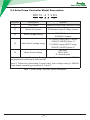
by
Solar Pump Inverter
TABLE OF CONTENTS
1. How it Works........................................................................01
1.1 General Introduction...............................................................................01
1.2 Pump Check Valve Requirements..........................................................02
1.3 Features.................................................................................................03
2. Solar Pump Controller General Information.........................05
2.1 Inspection..............................................................................................05
2.2 Descriptions and Features.....................................................................05
2.3 Protection Features...............................................................................06
2.4 Solar Pump Controller Model Description..............................................07
2.6 Solar Pump Controller Dimensions........................................................14
3. Installation............................................................................16
3.1 Installation Preparation & Requirements ..............................................17
3.2 Control Box and Controller Location Selection......................................18
3.3 Mounting Procedure..............................................................................19
4. Electrical Wiring...................................................................20
4.1 Terminals................................................................................................20
4.2 Power In DC Wiring ..............................................................................21
4.3 Ground Wiring........................................................................................22
4.4 Motor Wiring...........................................................................................23
4.5 Control Circuit Wiring (Optional)............................................................24
5. Start-up and Operation........................................................27
5.1 Keypad Description................................................................................27
5.2 Keypad Operation Process....................................................................28
5.3 Commissioning Procedure.....................................................................30
6. Three-Phase Motor Requirements.......................................35
7. Diagnostics and Troubleshooting.........................................36
7.1 Fault Codes............................................................................................37
7.2 Common Faults and Remedies..............................................................41
8. Periodic Maintenance..........................................................42
9. Solar Array ..........................................................................43
9.1 Example: 255W Monocrystalline Solar Array Curves...........................43
Appendix...................................................................................46
-I-
by
Solar Pump Inverter
Safety Information
NOTICE
Important information for installers of this equipment!
This equipment is intended for installation by technically qualified personnel.
Failure to install it in compliance with national and local electrical codes,and
within manufacturer recommendations, may result in electrical shock or fire
hazard, unsatisfactory performance, and equipment failure.
The installation information is available from pump manufacturers and
distributors, and directly from the solar pump controller manufacturers.
WARNING
Serious or fatal electrical shock may result from failure to connect the
motor,control enclosures, metal plumbing, and all other metal near the motor
or cable to a proper earth ground in accordance with local codes, using
wire no smaller than motor cable wires. To reduce risk of electrical shock,
disconnect power before working on or around the water system. Do not use
motor in swimming areas.
WARNING
High voltages (both AC and DC) capable of causing severe injury or death
by electrical shock are present in this unit. More than one disconnect switch
may be required to de-energize the equipment before servicing. This unit
should only be installed or serviced by technically qualified professionals.
Anytime working on or near the solar pump controller, or system:
• Turn OFF the external DC rated disconnect from the solar array to the solar
pump controller.
• Ensure AC power has been disconnected from the solar pump controller (if
used).
• Wait a minimum of 5 minutes after removing power from the solar pump
controller before servicing.
WARNING
Solar panels that have been exposed to full solar insolation for an extended
period of time can achieve high temperatures and could be a potential source
of burns to exposed skin if contacted. Use caution when working around
solar arrays.
- II -
by
Solar Pump Inverter
1. How it Works
1.1 General Introduction
The solar pumping system serves to provide water in remote applications where
electrical grid power is either unreliable or unavailable. The system pumps water
using a high-voltage DC power source such as an photovoltaic array of solar
panels(Which is abbreviated as solar array in this manual). Since the sun is only
available during certain hours of a day and only in good weather conditions,
the water is generally pumped into a storage pool or tank for further usage, and
water sources are those natural or special such as river, lake, well or waterway,
etc. Two level switches, one is High Level Switch, the other is Low Level Switch,
should be installed inside the pool or tank to regulate the water level. If the water
comes from a well, another two level switches should be installed inside the
well. The Low Level Switch of the well serves as an indication that the well has
run dry. The system will shut down to protect the pump and motor until the well
has recovered as the High Level Switch are reached by water. Figure 1 shows a
typical diagram of the solar pumping system. The major parts and components
in the system are listed after the diagram.
Figure 1 solar pumping system
- 01 -
by
Solar Pump Inverter
To be part of a water supply, the solar pumping system is designed which
consists of:
A. Solar Array
B. DC Breaker or Disconnect Switch
C. Solar Pump Controller
D. Pump and Motor
E. Water Source Level Switches (optional)
F. Tank Level Switches (optional)
The solar pump controller runs at variable speed to match the changing power
available from the solar array. Variable speed operation means there is no inrush or surge of energy during the pump/motor start-up, helping to eliminate
wear on the motor and pumping system. A leading cause of pump motor failure
is the stress applied to the motor during a full voltage start-up. The solar variable
speed operation ramps up the speed smoothly, which eliminates starting stress.
This feature enhances long-term motor reliability.
1.2 Pump Check Valve Requirements
In order to ensure maximum system reliability and water delivery, check valves
must be installed in the drop pipe. The first check valve must be installed at
the pump and additional check valves should be installed every 30m (100 ft)
of vertical pipe after the pump. See the pump owner’s manual for additional
information.
- 02 -
by
Solar Pump Inverter
1.3 Features
System Diagnostics
The solar pump controller continuously monitors system performance and
can detect a variety of abnormal conditions. In many cases, the controller will
compensate as needed to maintain continuous system operation; however, if
there is high risk of equipment damage, the controller will protect the system
and display the fault code. If possible, the controller will try to restart itself when
the fault condition subsides. See Diagnostics and Troubleshooting section for a
list of Fault Codes and corrective actions.
Motor Soft-Start
Normally, when there is a demand for water and power, the solar pump
controller will be operating. Whenever the solar pump controller detects a need
for water, the controller always “ramps up” the motor speed while gradually
increasing motor voltage, resulting in a cooler motor and lower start-up current
compared to conventional water systems. In cases where the demand for water
is low, the system may cycle on and off. Due to the controller’s soft-start feature
this will not harm the motor.
Over Temperature Foldback
The solar pump controller is designed for full power operation from a solar array
in ambient temperatures up to 60 °C. Under extreme thermal conditions, the
controller will reduce output power in an attempt to avoid shutdown. Full pump
output is restored when the controller temperature cools to a safe level.
Level Control Switch
Up to four level control switches can be wired into the solar pump controller
for water level control. This is optional and is not very necessarily required
to run the solar pump controller. The solar pump controller can be used with
one to four control switches, or none at all. This provides the user maximum
adjustability when using the solar pump controller. See INSTALLATION section
for more information on installing and using control switches.
Switching to Backup AC Power
The solar pump controller’s input power terminal may be switched manually
primary source (solar array), the controller draws from it to run the pump. The
solar pump controller can be manually switched to the alternate backup supply
input if:
- 03 -
by
Solar Pump Inverter
• The solar array input cannot provide at least 180 VDC(220VAC motor output)
or 350VDC (380VAC motor output) to successfully start the motor; AND
• Generator backup power is available at the AC backup terminals.
Note: Depending on the model number, solar pump controllers support power
input either 220VAC single phase, or 380VAC three phase, Please contact the
authorized agencies for details.
DC primary source power every 30 minutes. If the primary DC power is
available, shut down the controller, switch back to primary power and attempt to
run on DC power supply.
NOTICE
A DC circuit switch and a generator power switch must be installed, and
these two switches must be mechanically interlocked each other to prevent
switching on together resulting the solar PV and the generator being
connected to the solar pump controller simultaneously! Please check if
the design is in accordance with all applicable national and local electrical
codes.
- 04 -
by
Solar Pump Inverter
2. Solar Pump Controller General Information
The solar pump controller is a variable speed motor drive designed to run any
IEC three-phase asynchronous motor. The solar pumping system provides
water to remote locations by converting high voltage, direct current from a solar
array into alternating current to run a standard three-phase asynchronous motor.
When solar power is not available, the controller can be switched manually to an
alternate single-phase or three-phase AC input such as a generator or inverter
from battery, if available. The controller provides fault detection, motor soft
start, and speed control. The solar pump controller is designed to provide these
features with the plug and play ease of installation.
The solar pump controller is designed with the high standard of reliability.
The controller attempts to drive the pump and motor to deliver water even
under adverse conditions, reducing output as necessary to protect the system
components from damage, and only shutting down in extreme cases. Full
operation is restored automatically whenever abnormal conditions subside.
2.1 Inspection
Before you begin, receive and inspect the solar pump controller unit. Verify
that the part number is correct and that no damage has occurred during
transportation.
Note: solar pump controller is one component of the solar pumping system
which has other two optional components, solar array and AC pump with motor.
2.2 Descriptions and Features
The solar pump controller is based on a standard platform controlling a standard
three-phase asynchronous motor driving a pump powered by a solar array or an
optional AC generator backup.
The solar pump controller continuously monitors system performance and
incorporates a number of features for pumping system protection. In the event
of a fault, the solar pump controller will indicate the type of fault through the LED
display mounted on the front cover of controller.
The solar pumping system is optimized for pumping under adverse input
power conditions unique to solar arrays.
• Internal diagnostics will tolerate a lower input voltage.
• Whenever possible, the controller attempts to drive the pump load by
maximizing power output from the solar array.
- 05 -
by
Solar Pump Inverter
An easy–to–
enable remote system monitoring.
• A LED display provides a detailed indication of system status.
•
2.3 Protection Features
Electronic monitoring gives the controller the capability to monitor the system
and automatically shut down in the event of:
• Dry well conditions – with low level switch
• Bound pump – with auto-reversing torque
• High Voltage Surge
• Low Input Voltage
• Open motor circuit
• Short circuit
• Over heat
NOTE: This controller provides motor overload protection by preventing motor
current from exceeding rating current and by limiting the duty cycle in the event
of low water level. This controller does not provide over temperature sensing of
the motor.
- 06 -
by
Solar Pump Inverter
2.4 Solar Pump Controller Model Description
RPC 10 - 4 T 5 R 5
①
②
③ ④
⑤
Segment
Desctription
Options
①
RPC series
Renesola SolarPump Controller series
②
Series ID+Version
10:Standard type ID, Basic version
③
Motor Voltage Rating
2:220VAC 3 phase;
4:380VAC 3 phase
④
Solar Panel Voltage range
⑤
Motor Power Rating
S: 310VDC rating, MPPT range
280VDC-360VDC(Note 1)
T: 540VDC rating, MPPT range
500VDC-600VDC(Note 2)
004:4kW;
5R5:5.5kW;
R: decimal point
Note 1: Supporting Alternating Current input, with voltage rating of 220VAC
single phase connecting to terminal R&T.
Note 2: Supporting Alternating Current input, with voltage rating of 380VAC
three phase connecting to terminal R, S and T.
Table 1 Solar Pump Controller Model Description
- 07 -
by
Solar Pump Inverter
Controller Model
RPC10-2SR75 RPC10-2S1R5 RPC10-2S2R2
Input Data
PV Source
Max Input Voltage(Voc)[V]
450V
Min Input Voltage, at mpp[V]
180V
Recommended voltage, at mppt
280VDC~360VDC
Max Amps Input[A]
4.3
8.6
12.5
Recommended Max Power at mppt[kW]
1.2
2.4
3.5
Alternate AC Generator
Input voltage
220/230/240V AC(±15%), Single Phase
Max Amps(RMS)[A]
8.2
14.0
23.0
Power and VA capability[kVA]
2.0
5.0
7.5
0.75
1.5
2.2
Output Data
Output Power,rated[kW]
Output Voltage, rated
220/230/240V AC, Three Phase
Max Amps(RMS)[A]
4.5
Output Frequency
7.0
10
0-50Hz/60Hz
Protection
Surge protection
Integrated
Overvoltage protection
Integrated
Undervoltage protection
Integrated
Locked pump protection
Integrated
Open circuit protection
Integrated
Short circuit protection
Integrated
Overheated protection
Integrated
Dry run protection
Integrated
General Data
Ambient Temperature Range
-20°C~60°C; >45°C, Derating as required
Cooling Method
Fan Cooling
Ambient Humidity
≤ 95%RH
Dimensions(H*W*D)[mm]
151.7*101*126.8
Gross Weight[kg]
1.4
Standard Warranty[month]
Certificates
18
IEC/EN 61800-5-1,IEC/EN 61800-2:2004,
IEC/EN 61800-3:2004,CE
- 08 -
by
Solar Pump Inverter
Controller Model
RPC10-4TR75 RPC10-4T1R5 RPC10-4T2R2
Input Data
PV Source
Max Input Voltage(Voc)[V]
750V
Min Input Voltage, at mpp[V]
350V
Recommended voltage, at mpp
500VDC~600VDC
Max Amps Input[A]
2.4
4.8
7.0
Recommended Max Power at mpp[kW]
1.2
2.4
3.5
Alternate AC Generator
Input voltage
380V AC(±15%), Three Phase
Max Amps(RMS)[A]
3.4
5.0
5.8
Power and VA capability[kVA]
2.2
3.3
5.0
1.5
2.2
Output Data
Output Power,rated[kW]
0.75
Output Voltage, rated
380V AC , Three Phase
Max Amps(RMS)[A]
2.5
Output Frequency
3.7
5.0
0-50Hz/60Hz
Protection
Surge protection
Integrated
Overvoltage protection
Integrated
Undervoltage protection
Integrated
Locked pump protection
Integrated
Open circuit protection
Integrated
Short circuit protection
Integrated
Overheated protection
Integrated
Dry run protection
Integrated
General Data
Ambient Temperature Range
-20°C~60°C; >45°C, Derating as required
Cooling Method
Fan Cooling
Ambient Humidity
≤ 95%RH
Dimensions(H*W*D)[mm]
151.7*101*126.8
Gross Weight[kg]
1.4
Standard Warranty[month]
Certificates
1.4
1.5
18
IEC/EN 61800-5-1,IEC/EN 61800-2:2004,
IEC/EN 61800-3:2004,CE
- 09 -
by
Solar Pump Inverter
Controller Model
RPC10-4T004 RPC10-4T5R5 RPC10-4T7R5
Input Data
PV Source
Max Input Voltage(Voc)[V]
750V
Min Input Voltage, at mpp[V]
350V
Recommended voltage, at mpp
500VDC~600VDC
Max Amps Input[A]
12.8
17.6
24.0
Recommended Max Power at mpp[kW]
6.4
8.8
12.0
Alternate AC Generator
Input voltage
380V AC(±15%), Three Phase
Max Amps(RMS)[A]
10.0
15.0
20.0
Power and VA capability[kVA]
6.6
9.0
13.0
5.5
7.5
Output Data
Output Power,rated[kW]
4.0
Output Voltage, rated
380V AC , Three Phase
Max Amps(RMS)[A]
9.0
Output Frequency
13.0
17.0
0-50Hz/60Hz
Protection
Surge protection
Integrated
Overvoltage protection
Integrated
Undervoltage protection
Integrated
Locked pump protection
Integrated
Open circuit protection
Integrated
Short circuit protection
Integrated
Overheated protection
Integrated
Dry run protection
Integrated
General Data
Ambient Temperature Range
-20°C~60°C; >45°C, Derating as required
Cooling Method
Fan Cooling
Ambient Humidity
≤ 95%RH
Dimensions(H*W*D)[mm]
249.5*155.5*159.5
Gross Weight[kg]
3.4
Standard Warranty[month]
Certificates
3.5
3.6
18
IEC/EN 61800-5-1,IEC/EN 61800-2:2004,
IEC/EN 61800-3:2004,CE
- 10 -
by
Solar Pump Inverter
Controller Model
RPC10-4T011 RPC10-4T015 RPC10-T18R5
Input Data
PV Source
Max Input Voltage(Voc)[V]
750V
Min Input Voltage, at mpp[V]
350V
Recommended voltage, at mpp
500VDC~600VDC
Max Amps Input[A]
35.2
48.0
57.6
Recommended Max Power at mpp[kW]
17.6
24.0
29.6
Alternate AC Generator
Input voltage
380V AC(±15%), Three Phase
Max Amps(RMS)[A]
26.0
35.0
38.0
Power and VA capability[kVA]
17.0
23.0
25.0
15.0
18.5
Output Data
Output Power,rated[kW]
11.0
Output Voltage, rated
Max Amps(RMS)[A]
380V AC, Three Phase
25.0
Output Frequency
32.0
37.0
0-50Hz/60Hz
Protection
Surge protection
Integrated
Overvoltage protection
Integrated
Undervoltage protection
Integrated
Locked pump protection
Integrated
Open circuit protection
Integrated
Short circuit protection
Integrated
Overheated protection
Integrated
Dry run protection
Integrated
General Data
Ambient Temperature Range
-20°C~60°C; >45°C, Derating as required
Cooling Method
Fan Cooling
Ambient Humidity
≤ 95%RH
364*214*190.5
Dimensions(H*W*D)[mm]
Gross Weight[kg]
9.8
Standard Warranty[month]
Certificates
9.8
10.0
18
IEC/EN 61800-5-1,IEC/EN 61800-2:2004,
IEC/EN 61800-3:2004,CE
- 11 -
by
Solar Pump Inverter
Controller Model
RPC10-4T022 RPC10-4T030 RPC10-4T037
Input Data
PV Source
Max Input Voltage(Voc)[V]
750V
Min Input Voltage, at mpp[V]
350V
Recommended voltage, at mpp
500VDC~600VDC
Max Amps Input[A]
70.4
96.0
118.4
Recommended Max Power at mpp[kW]
35.2
48.0
59.2
Alternate AC Generator
Input voltage
380V AC(±15%), Three Phase
Max Amps(RMS)[A]
46.0
62.0
76.0
Power and VA capability[kVA]
30.0
41.0
50.0
30.0
37.0
Output Data
Output Power,rated[kW]
22.0
Output Voltage, rated
Max Amps(RMS)[A]
380V AC, Three Phase
45.0
Output Frequency
60.0
75.0
0-50Hz/60Hz
Protection
Surge protection
Integrated
Overvoltage protection
Integrated
Undervoltage protection
Integrated
Locked pump protection
Integrated
Open circuit protection
Integrated
Short circuit protection
Integrated
Overheated protection
Integrated
Dry run protection
Integrated
General Data
Ambient Temperature Range
-20°C~60°C; >45°C, Derating as required
Cooling Method
Fan Cooling
Ambient Humidity
≤ 95%RH
Dimensions(H*W*D)[mm]
Gross Weight[kg]
424*285*210.3
17.2
Standard Warranty[month]
Certificates
17.2
17.6
18
IEC/EN 61800-5-1,IEC/EN 61800-2:2004,
IEC/EN 61800-3:2004,CE
- 12 -
by
Solar Pump Inverter
Controller Model
RPC10-4T045 RPC10-4T055 RPC10-4T075
Input Data
PV Source
Max Input Voltage(Voc)[V]
750
Min Input Voltage, at mpp[V]
350
Recommended voltage, at mpp
500VDC~600VDC
Max Amps Input[A]
144.0
176.0
240.0
Recommended Max Power at mpp[kW]
72.0
88.0
120.0
Alternate AC Generator
Input voltage
380V AC(±15%), Three Phase
Max Amps(RMS)[A]
90.0
110.0
140.0
Power and VA capability[kVA]
59.2
72.4
92.0
55.0
75.0
Output Data
Output Power,rated[kW]
45.0
Output Voltage, rated
Max Amps(RMS)[A]
380V AC, Three Phase
90.0
Output Frequency
105.0
150.0
0-50Hz/60Hz
Protection
Surge protection
Integrated
Overvoltage protection
Integrated
Undervoltage protection
Integrated
Locked pump protection
Integrated
Open circuit protection
Integrated
Short circuit protection
Integrated
Overheated protection
Integrated
Dry run protection
Integrated
General Data
Ambient Temperature Range
-20°C~60°C; >45°C, Derating as required
Cooling Method
Fan Cooling
Ambient Humidity
≤ 95%RH
544*380*284.8
Dimensions(H*W*D)[mm]
Gross Weight[kg]
42.2
Standard Warranty[month]
Certificates
42.6
650*473*318
71.0
18
IEC/EN 61800-5-1,IEC/EN 61800-2:2004,
IEC/EN 61800-3:2004,CE
- 13 -
by
Solar Pump Inverter
2.6 Solar Pump Controller Dimensions
There are three types of solar pump controller dimensions, as following
Figure2~4 showing. Table 3 lists all the frame sizes and mounting
dimensions.
Figure 2. 0.75~2.2kW Controller Dimensions
Figure 3. 4~7.5kW Controller Dimensions
- 14 -
by
Solar Pump Inverter
Figure 4. 11~75kW Controller Dimensions
Controller
Model
Mounting
Dimension
(mm)
D
Mounting
Hole
Diameter
(mm)
101
126.8
Φ5
151.7
101
126.8
Φ5
237
249.5
155.5
159.5
Φ5.9
156.6
378.3
364
396
214
221.7
190.5
Φ6
235
447
424
463
285
289.6
210.3
Φ7
260
580
544
595.5
380
390
284.8
Φ10
343
674
650
701.5
473
485
318
Φ10
Outline Dimension(mm)
A
B
H
92
142.7
151.7
92
142.7
144.4
H1
W
W1
RPC10-2SR75
RPC10-2S1R5
RPC10-2S2R2
RPC10-4TR75
RPC10-4T1R5
RPC10-4T2R2
RPC10-4T004
RPC10-4T5R5
RPC10-4T7R5
RPC10-4T011
RPC10-4T015
RPC10-4T18R5
RPC10-4T022
RPC10-4T030
RPC10-4T037
RPC10-4T045
RPC10-4T055
RPC10-4T075
Table 3 Solar Pump Controller Dimensions
- 15 -
by
Solar Pump Inverter
3. Installation
WARNING
High voltages (both AC and DC) capable of causing severe injury
or death by electrical shock are present in this unit. This unit should
only be installed or serviced by technically qualified professionals.
Anytime working on or near the solar pump controller, or system:
• Turn OFF the external DC rated disconnect from the solar array to the
solar pump controller.
• Ensure AC power has been disconnected from the solar pump
controller (if used).
• Wait a minimum of 5 minutes after removing power from the solar
pump controller before servicing.
READ THESE INSTRUCTIONS COMPLETELY BEFORE
INSTALLATION.
Note: During installation, if a conflict arises between this manual
and local or national electrical codes, the applicable local or national
electrical codes should prevail.
• The longevity and performance of the solar pumping package may be
adversely affected by improper installation.
• The solar array structure, modules, and wiring harness must be
properly assembled according to the manufacturer’s installation
instructions before installing the solar pump controller.
• Wiring Requirements: Use 75 °C rated wire sized for a maximum
voltage drop of 3% per local electric codes.
- 16 -
by
Solar Pump Inverter
3.1 Installation Preparation & Requirements
When installing the solar pump controller, be aware that:
• High voltage is present in the controller when powered on; use caution
when live DC power is on.
• Do not allow any unauthorized persons near the solar array and
connection sites while power is applied.
• It is strongly recommended that a DC rated disconnect box be used
to disconnect the incoming DC power from the solar pump controller
during installation and maintenance. Use a Volt Meter to confirm the
absence of voltage in the line before proceeding with installation or
maintenance.
• The DC disconnect should be sized to be capable of adequately
disconnecting the output open circuit voltage (Voc) and short circuit
current (Isc) of the solar array.
•
dry brush and vegetation.
• For optimal performance, avoid placing the solar array around any
objects that can cast shadows or reduce sunlight to the array.
• Install the solar pump controller in a control box with control terminals
and power wiring. Install the control box out of direct sunlight to prevent
overheating and reduced performance. The optimum location is on the
mounting pole for the solar array underneath the array for protection
from the sun, heat, and weather elements.
• Keep the surrounding area clear of vegetation.
•
• Limit access of animals to the system.
• Protect wires from damage from wildlife and weathering by using
conduit. For additional protection, bury the conduit in the ground.
- 17 -
by
Solar Pump Inverter
3.2 Control Box and Controller Location Selection
The solar pump controller
is intended for operation
in ambient temperatures
up to 60 °C. The following
recommendations will
help in the selection of
the proper location for the
solar pump controller .
Figure 5 Control Box and Controller Location
CAUTION
When using an alternate AC power source, the ambient temperature
is limited to 40 °C for full power delivery.
• The solar pump controller must be installed into a control box which
has a tight enclosure to avoid direct sunshine , rain, dust, moisture,
animals, plants, etc. The control box should has a bottom gland plate for
installing wire cord or conduit. To decide the size of control box, Please
refer to the following Figure 6.
Figure 6 Ventilation Arrangement and Required Distances
- 18 -
by
Solar Pump Inverter
• The control box should be mounted on a sturdy supporting structure
such as a wall or supporting post. Please take into account the weight
of the unit.
• The electronics inside the solar pump controller are air-cooled. As a
result, there should be at least 50 cm both above and below to allow for
make sure that it is at least 50 cm beneath the array.
• The solar pump controller should be mounted with the wiring end
oriented downward. The control box should not be placed in direct
sunlight or other locations subject to extreme temperatures or humidity
(mounting location should not be subjected to freezing conditions).
Placing the control box in direct sunlight or high ambient temperatures
will result in reduced performance due to temperature foldback
protection of the solar pump controller. For optimum performance,
maximize the shading of the control box.
3.3 Mounting Procedure
• Disconnect all electrical power supply.
• Install the control box with solar pump controller inside to a secure
post using mounting screws (not included). The top mounting holes
are slotted in order to hang the controller in place, while the bottom
fasteners are inserted to secure the unit from ever sliding up.
• If the mounting surface is narrower than the outer mounting slots, use
the top center and bottom center mounting holes and secure mounting
screws (not included).
- 19 -
by
Solar Pump Inverter
4. Electrical Wiring
4.1 Terminals
Note: Terminals are different in shapes and combinations, depending
on different sizes of solar pump controller.
Figure 7 Terminals Arrangement of solar pump controller
(11kW size, with lower part of front cover been cut away.)
Figure 8. Main terminals (11kW)
Figure 9. Control terminals (11kW)
- 20 -
by
Solar Pump Inverter
WARNING
Capacitors inside the solar pump controller can still hold lethal
voltage even after power has been disconnected. Allow 5 minutes for
dangerous internal voltage to discharge before removing solar pump
controller cover to access the terminals.
4.2 Power In DC Wiring
For Solar Pumping Systems, a two-pole DC disconnect switch must be
installed between the solar array and the solar pump controller.
Connect the cables which comes from the two-pole DC disconnect
Switch downstream terminals marked with “+” and “-”(positive and
negative poles of Solar panel output), to solar pump controller ’s
terminals block labeled as “R”, “T” . (Do not over-tighten the screws.).
See Figure 11.
WARNING
Before connect DC wiring, following the steps below to prevent
hazardous electric shock resulting in serious injury or device burning.
• Make sure that the external DC disconnect switch is off.
• Make sure that AC power is disconnected (if AC power supply is
wired as backup power)
• Make sure that all wires are properly identified and marked:
(a) the cable from the PV to the external DC disconnect switch
(b) the cable from the external DC disconnect to the solar pump
controller
- 21 -
by
Solar Pump Inverter
CAUTION
Do not connect a solar array directly to the DC input of the solar
pump controller without protection such as DC disconnect switch.
In this controller, the integral solid state short circuit protection of
motor wiring does not provide circuit protection of wiring for input
power. Input wiring protection must be provided in accordance with
all applicable national and local electrical codes. In addition, follow
any manufacturer’s recommendations for protection of a photovoltaic
(PV) array and protection of a generator, if used.
4.3 Ground Wiring
Ground terminal(GND) is labeled as this icon
. Please refer to the
instruction to this icon, or other equivalent icon or sign by local electrical
codes or international standard.
Connect the ground wire to the ground terminal of solar pump controller.
Correct Grounding helps to prevent shock hazard if there is a fault in the
motor .
See Figure 11.
WARNING
Serious or fatal electrical shock may result from failure to connect
the ground terminal to the motor, the solar pump controller, metal
plumbing and all other metal near the motor, or cable to a proper
earth ground in accordance with local codes, using wire no smaller
than motor cable wires. To minimize risk of electrical shock,
disconnect power before working on or around the solar pumping
system. Do not use motor in swimming areas.
- 22 -
by
Solar Pump Inverter
4.4 Motor Wiring
Connect the cable with four wires from the Motor to the controller
terminal block to terminals U, V, W, and GND (See Figure 11). (Do not
over-tighten the screws.).Motors with international leads are as shown
in the table in Figure 10. Check motor lead color to ensure correct
installation.
Note: To reverse direction of motor rotation, reverse any two wires.
US
Black(BLK)
Red (RED)
International
Gray (GRY)
Black (BLK) Browm(BRN) Ground (GND)
Yellow (YEL)
Figure 10. Motors with international leads
Figure 11. Main Terminals Wiring
- 23 -
Ground (GND)
by
Solar Pump Inverter
4.5 Control Circuit Wiring (Optional)
The solar pump controller can be operated with control switches to
control the controller ON/OFF, and water level switch sensing and
control High/Low pumping range. Use a normally closed low-voltage
control switch with a contact rating suitable for instrumentation use (i.e.
Max: 24 V 15mA)
4.5.1 ON/OFF Control Switch Operation(Optinaltion)
• Solar pump controllers can be turned ON/OFF by a control terminal
input. See Figure 12 for details. Note: F0.01 must be changed to 1
while the ON/OFF Control Switch is needed.
Figure 12. ON/OFF Control Switch Circuit Wiring Connections
4.5.2 Well Level Switch Operation
The solar pump controller is designed to utilize 2 level switches for
well water level control. One is HIGH level, the other is LOW level. See
Figure 13 for wiring connection.
Both HIGH and LOW level switch can be set to NO or NC contact type
from the USER DEFINABLE PARAMETER F5.27.
When the LOW level switch acts as the water falls below LOW level
threshold, the solar pump controller stops the pump, thus prevents the
well water from exhausting, in some case also protect the well.
When the HIGH level switch acts as the water rises higher than HIGH
level threshold, the solar pump controller starts the pump. Set the HIGH
and LOW level switch threshold to appropriate value, thus prevent the
pump from switching on and off frequently.
See USER DEFINABLE PARAMETER F5.27 in operation section of
manual for instructions .
- 24 -
by
Solar Pump Inverter
4.5.3 Tank Level Switch Operation
The solar pump controller is designed to utilize 2 level switches for Tank
or pool water level control. One is HIGH level, the other is LOW level.
See Figure 13 for wiring connection.
Both HIGH and LOW level switch can be set to NO or NC contact type
from the USER DEFINABLE PARAMETER F5.27.
When the LOW level switch acts as the water falls below LOW level
threshold, the solar pump controller starts the pump, thus supply water
to the tank or pool.
When the HIGH level switch acts as the water rises higher than HIGH
level threshold, the solar pump controller stops the pump, to prevents
water overflow. Set the HIGH and LOW level switch threshold to
appropriate value, thus prevent the pump from switching on and off
frequently.
See USER DEFINABLE PARAMETER F5.27 in operation section of
manual for instructions.
Once it shuts off, the solar pump controller then waits to run again until
the switch reads “CLOSED”.
Figure 13. Well/Tank Water Level Switch Wiring Connections
- 25 -
by
Solar Pump Inverter
4.5.4 Well & Tank Level Switches Position
Figure 14 shows the demo of four level Switches installation position .
Figure 14. Demo of Well & Tank Level Switches Installation
CAUTION
Tank level switch configurations are superseded by the Well level
switch. If the well switch detects low flow it will “OPEN” and override
the run signals sent by the tank level switches to protect the well,
motor and controller.
4.5.5 System Wiring Diagram
Figure 15. System Wiring Diagram
- 26 -
by
Solar Pump Inverter
5. Start-up and Operation
5.1 Keypad Description
Figure 16 Keypad Schematic Diagram
5.1.1 Button Function Description
Symbol
Button Name
PRGM
Program/ Exit
ENT
Data enter
Function Description
Enter or exit of menu, parameter setting
Progressively enter menu and confirm parameter.
UP/ increase
Progressively increase setting value or function
codes.
DOWN/
decrease
Progressively decrease setting value or function
codes.
≤
Shift
Use it to select displayed parameters cyclically
during running or stop status. In parameter
setting mode, press this button to select the bit to
be modified.
RUN
Run
STOP/
RESET
Stop/reset
REV/JOG
Shortcut
Start to run the controller in keypad control mode.
In running status, restricted by function code
F7.04, it can be used to stop the controller,
In malfunction alarm status, not restricted by
function code F7.04, it can be used to reset the
controller.
Determined by function code F7.03.
- 27 -
by
Solar Pump Inverter
5.1.2 Functional LED indicator description
Indicator Name
RUN
Description
Light on: controller running status.
STOP
Light on: controller stops or fault status.
FWD
Lights of FWD and RUN are on at the same time: controller
forward running status.
REV
Lights of REV and RUN are on at the same time: controller
reversely running status.
5.2 Keypad Operation Process
5.2.1 Parameter Setting
Three levels of menu are as following:
•
• Function code (second-class)
• Setting parameter of function code (third-class)
5.2.2 Remarks
Pressing PRGM or ENT can return to the second-class menu from the
third-class menu. The difference is: Pressing ENT will save the setting
parameters into control board, and return to the second-class menu
with shifting to the next function code automatically. While pressing
PRGM will directly return to the second-class menu without saving the
parameters, and keep staying at the current function code.
For example: change the parameter 00.50Hz of function code F1.01
Under the third-class menu, if the parameter has no flickering bit, it
include:
(1) The parameter of this function code can’t be modified, such as
actually detected parameter, operation records and so on.
(2)
- 28 -
by
Solar Pump Inverter
Figure 17 Flow Chart of Parameter Setting
5.2.3 Fault Reset
When controller malfunction occurs, it will display the relative fault
information. Use the STOP/ RESET key or terminals (determined by F5
group) to reset the fault. After fault reset, controller is at stand-by status.
If no fault reset when controller is at fault status, it will keep operation
protection status and cannot run.
- 29 -
by
Solar Pump Inverter
5.3 Commissioning Procedure
• Check and make sure wiring are correct. If needed, take a megger to
test the insulation of motor, cable, etc.
• Use a multimeter to test the PV output voltage at the DC switch.
• Power on the controller by switch on the DC switch.
• If necessary, modify and set the parameters of motor to the controller.
With the pump ready, Jog the motor shortly by ON/OFF control switch
with F0.01 set to 1 ,or RUN/STOP on keypad with F0.01 set to 0, to see
if the running direction of pump are correct. If the direction is wrong,
change the motor wiring connections by shifting two leads according to
Pump/Motor Wiring Connections section, or you can change Parameter
drive the motor in another direction.
• Make sure the level switches’ contact type is compatible with the
settings of Parameter F5.27. If not, change the settings.
•
• Check if the tank and well level switches are functioning well.
• Let the system work an hour, test the water supply capacity.
•
- 30 -
by
Solar Pump Inverter
that is effective on solar pump controllers.
“◎
Function
Code
Function
Descriptions
Factory
Setting
Modification
Type
0
●
4
●
0
●
0.01Hz
60.00Hz
●
0.01Hz
20.00Hz
○
2
○
10.0s
○
Minimum
Unit
F0 Group: Basic Parameters
F0.01
0:Keypad
Run
command source 1:Terminals
0: Digital Setting
Modified by Up/down
key
1: Potentiometer of
panel
2: AVI terminal
3: ACI terminal
4: Automatically
M a i n Fr e q u e n c y
F0.03
adjusted by Light
Source X Selection
intensity
5: Reserved
6: Multi-function digital
input terminals
7: PLC
8: PID
9: Communication
interface
F0.09
Running
direction
selection
F0.10
Max. output
frequency
0: Forward
1: Reverse
2: Reverse running
prohibited
10.00~ 600.0Hz
F0.14
Low limit of running
0.00Hz~ F0.12
frequency
F0.15
0: Running at low limit
Options at low limit frequency
frequency
1: Stop
2: Sleep at 0Hz
F0.19
Deceleration time 1 0.1 ~ 3600s
- 31 -
0.1s
by
Solar Pump Inverter
F0.20
Default setting
0:Not restore to default
setting
1: Restore to factory
setting
2:Fault record clearing
F0.21
Parameter lock
setting
0: Unlock parameter
1: Lock parameter
0
●
1
○
0.1kW
Different
according to
controller model
●
0.01Hz
50.00Hz
●
1V
Different
according to
controller model
●
0.1A
Different
according to
controller model
●
F2 Group: Motor Parameters
F2.01
F2.02
Motor rated power 0.4~700.0kW
Motor rated
frequency
10.00Hz~ F0.10
F2.04 Motor rated voltage 0~480V
F2.05
Motor rated current 0.8~2000A
F5 Group: Digital Input Terminal Functions
F5.00~
M1~M6 terminal
F5.05
function
F5.27
0:Invalid
1:Forward
2:Reverse
39:Well High Level
Limit
40:Well Low Level
Limit
41:Tank High Level
Limit
42:Tank Low Level
Limit
BIT0 for M1
0:N0:NO 1:NC
O 1:NC
BIT1 for M2
0:NO 1:NC
M1~M6 Normally BIT2 for M3
Open/Normally 0:NO 1:NC
BIT3 for M4
Close Options
0:NO 1:NC
BIT4 for M5
0:NO 1:NC
BIT5 for M6
0:NO 1:NC
F5.00 = 1
F5.01 = 2
F5.02 = 39
F5.03 = 40
○
F5.04 = 41
F5.05 = 42
0C
○
12
○
F6 Group: Output Terminal Parameters
F6.02
Relay 1 output
selection
12:Input Over Voltage
Fault
- 32 -
by
Solar Pump Inverter
F7 Group: Display Interface Parameters
F7.00
User password
F7.10
controller firmware
version
0~9999
0
○
◎
FA Group: Protection and Malfunction Parameters
FA.14
FA.15
FA.16
Fault
0: No fault
Record of the one 1: Inverter module
before last
protection (E001)
2. Over-current when
accelerate (E002)
3: Over-current when
decelerate (E003)
Last Fault Record
4: Over-current at
constant speed (E004)
5: Over-voltage when
accelerate (E005 )
6: Over-voltage when
decelerate (E006)
7: Over-voltage at
constant speed (E007)
8:Hardware
overvoltage (E008)
9:Under voltage
(E009)
10:controller overload
(E010)
11:Motor overload
(E011)
12:Phase-lack of input
(E012)
13:Phase-lack of
output (E013)
Current Fault
14:Heatsink
Record
overheating (E014)
15:External fault
(E015)
16:Communication
fault (E016)
17:Reserved
18:Current detection
fault (E018)
19:Motor autotuning
fault (E019)
20:Well Level
Fault(E020)
21:Tank Level
Fault(E021)
22:EEPROM fault
(E022)
- 33 -
◎
◎
◎
by
Solar Pump Inverter
FA.17
Running frequency
when fault occurs
Hz
◎
FA.18
Output current
when fault occurs
A
◎
FA.19
DC bus voltage
when fault occurs
V
◎
FD Group: Solar pumping special parameters
FD.05
FD.06
Max power point
voltage
Photovoltaic open
0-800
circuit voltage
FD.07 Power on auto start
FD.08
0-700
Delay
before auto start
Volt
220VAC motor
controller:
360VDC
380VAC motor
controller:
600VDC
○
Volt
220VAC motor
controller:
450V
380VAC motor
controller:
750VAC
○
1
○
5.0
○
0:Disable
1:Enable
0.0-900.0
WARNING
0.1s
Do NOT touch any other piece inside the solar pump controller
while power is applied. To service any other areas of the controller,
disconnect ALL power sources and wait 5 minutes before continuing.
- 34 -
by
Solar Pump Inverter
6. Three-Phase Motor Requirements
Normally, considering about the selection of solar pump controller, the
motor’s power rating should be equal to controller’s power rating.
But if the length of cable for motor wiring is more than 50m to
100m(depends on motor power rating, the smaller the motor power
rating is, the short length are required), the controller’s power rating
should be larger than the motor. For example, to an application of 100m
deep well , a 5.5kW controller should be selected to control 4kW motor.
- 35 -
by
Solar Pump Inverter
7. Diagnostics and Troubleshooting
The solar pump controller will attempt to drive the pump to deliver water
even under adverse conditions. To ensure years of reliable service, it
must also protect the system components from conditions that might
result in equipment damage. When adverse conditions arise, the
controller will continue to deliver as much water as possible at reduced
output if necessary, and will shut down only in extreme cases. Full
operation will resume automatically whenever abnormal conditions
subside.
Error conditions may suspend certain features, reduce output, or shut
down operation of the controller for varying amounts of time depending
on the nature and severity of the error. Problems that merely reduce
features or performance generally restore full operation when the
trouble condition subsides without stopping the pump or flashing an
error code. An severe error such as short circuit or over current requires
stopping the motor immediately. An overload error stops the controller
with a delay by time-load curves defined internally. The error code is
shown on the LED display.
If the controller has stopped to indicate a fault code on the display, the
associated time-out delay will vary depending on the nature of the fault.
The number following the “E” symbol corresponds to the error code for
the offending condition.
- 36 -
by
Solar Pump Inverter
7.1 Fault Codes
Fault
Fault description
code
Possible causes
Remedy
Too short acceleration
Increase acceleration time
time
E001
E002
E003
IGBT module
fault
Over-current
during
acceleration
Over-current
during
deceleration
Damaged IGBT module Ask for support
Malfunction caused by Inspect external equipment
interference
and eliminate interference
Improperly grounding
Check grounding wire
Too fast acceleration
Increase acceleration time
Too low input voltage
Check the input power supply
or wiring
lower-rating controller
Replace with higher-rating
controller
Too-fast deceleration
Increase deceleration time
Too-heavy and largeinertia load
Add proper braking units
lower-rating controller
Replace with higher-rating
controller
Sudden change of load Check the load
Over-current at
Too low input voltage
E004 constant running
speed
lower-rating controller
E005
Over-voltage
during
acceleration
E006
Over-voltage
during
deceleration
Check the input power supply
or wiring
Replace with higher-rating
controller
Abnormal input voltage Check input power
Restart the motor when
Avoid prompt restart when
instantaneous trip-off
trip-off
occurs
Too-fast deceleration
Increase deceleration time
Too-heavy and largeinertia load
Add proper braking units
Abnormal input voltage
Check input power supply or
wiring
Over-voltage at Abnormal input voltage Install proper input AC reactor
E007 constant running
Large-inertia load
Add proper braking units
speed
- 37 -
by
Solar Pump Inverter
Fault
Fault description
code
Possible causes
Remedy
Check input power supply or
Abnormal input voltage
wiring
Hardware overE008
voltage
Too-fast deceleration Increase deceleration time
Large-inertia load
E009
Under voltage of
Too-low input voltage
DC bus
Too fast acceleration
E010
E011
Controller
overload
Increase acceleration time
Too-low input voltage
Check input power supply or
wiring
Too-heavy load
Replace with higher-rating
controller
Too-low input voltage
Check input power supply or
wiring
Improper setting of
motor rated current
Properly setting of motor
rated current
Motor overload Improper motor’s
overload protection
threshold
E012 Input phase loss Phase-loss of R, S, T
Output phase
loss
Check input power supply or
wiring
Restart the motor when
Avoid prompt restart when
instantaneous trip-off
trip-off
occurs
lower-rating controller
E013
Add proper braking units
broken wires in the
output cable
broken wires in the
motor winding
Loose output terminals
- 38 -
Check load and boost the
torque
Replace with higher-rating
controller
Check input power supply or
wiring
Check the wiring and
installation
by
Solar Pump Inverter
Fault
Fault description
code
E014
Controller
overheat
Possible causes
Remedy
Instantaneous
overcurrent of
controller
Refer to over current remedy
Output short circuit
Re-wiring of output
Cooling fans of
Replace cooling fan and clear
controller stopped or
the ventilation channel
damaged. Obstruction
of ventilation channel
Too-high ambient
temperature
Decrease the ambient
temperature if possible
loose cables or
terminals
Inspect and tighten the wire
and terminals
Abnormal power circuit
Abnormal control PCB Ask for support
board
E015
E016
External fault
Faults tripped by
external fault input
terminals
Inspect external equipment
Improper baud rate
setting
Set proper baud rate
Communication Receive wrong data
fault
Long-time
communication
interruption
E017
Check communication
devices and cables
Reserved
Loose wires or
connectors of control
board
E018
Push STOP/RESET to reset
and ask for support
Current
detection fault
Amplifying circuit
abnormal
Hall sensor is damaged
Check the wiring and
connectors
Ask for support
Power circuit abnormal
E019 Auto-tuning fault
Inconsistence between Replace with the propercontroller and motor
rating controller
Improper setting of
Set rated parameters
motor rated parameters according to motor nameplate
- 39 -
by
Solar Pump Inverter
Fault
Fault description
code
Possible causes
Bigger tolerance of
parameters against
standard parameters
E019 Auto-tuning fault after auto tuning.
E020
E021
E022
Well Level
Fault (E020)
Remedy
Make motor uncoupled with
load and auto-tune again
Overtime of auto tuning
Check motor wiring and
parameters setting
Dry well or slow water
recovery
Waiting water recovery, or reinstall the pump.
Tank Level
High level limit is
Fault(E021)
reached.
before auto start
Read/ Write fault of
EEPROM fault control parameters
EEPROM damaged
- 40 -
Wait until water level comes
below the low level limit, and
then the solar pump controller
will start the pump again.
Push STOP/RESET to reset
Ask for support
by
Solar Pump Inverter
7.2 Common Faults and Remedies
Controller may have following faults or malfunctions during operation,
please refer to the following remedies.
7.2.1 No display after power on:
(1) Inspect whether the voltage of power supply is the same as the
controller rated voltage or not with multi-meter. If the power supply has
problem, inspect and solve it.
(2) Inspect whether the three-phase rectify bridge is in good condition
7.2.2 Power supply switch trips off when power on:
(1) Inspect whether the input power supply is grounded or short circuit.
Solve this problem.
(2) Inspect whether the rectify bridge has been burnt or not. If it is
damaged, ask for support.
7.2.3 Motor doesn’t run after controller works:
(1) Inspect if there is balanced three-phase output among U, V, W. If
yes, then motor could be damaged, or mechanically locked.
(2) If the output is unbalanced or lost, the controller drive board or the
output module may be damaged, ask for support..
7.2.4 Controller displays normally when power on, but switch at
the input side trips when running:
(1) Inspect whether the output side of controller is short circuit. If yes,
ask for support.
(2) Inspect whether ground fault exists. If yes, solve it.
(3) If trip happens occasionally and the distance between motor and
controller is too far, it is recommended to install output AC reactor.
(4) Inspect whether the output module is burnt or not. If yes, ask for
support.
- 41 -
by
Solar Pump Inverter
8. Periodic Maintenance
• Solar pump controller:
Periodically checking of Status display, error code display and fault
needed.
• Solar panels:
Periodically cleaning of the surface of panels and checking wiring are
required. Please refer to manufacturer’s instruction.
• Solar motor and pump:
refer to manufacturer’s instruction.
- 42 -
by
Solar Pump Inverter
9. Solar Array
9.1 Example: 255W Monocrystalline Solar Array Curves
Displaying Diminishing Solar Light Intensity
Figure 18. example solar array Curves
Each panel having the following values at standard test conditions
2
(STC of 1000 W/m , 25 deg C panel temp): Isc = 8.63A, Voc =36.6 Vdc,
Imp = 7.92 A, Vmp = 31.18 Vdc
2
2
W/m steps, at constant 25 deg. C panel temperature.
- 43 -
in 200
by
Solar Pump Inverter
Solar Panels Wired in Series When solar panels are wired in series, the
positive terminal of one solar panel is wired in to the negative terminal
of the next solar panel. When panels are connected in series:
• Voltage accumulates (adds) for each panel in series
• Wattage accumulates (adds) for each panel in series
• Current (Amps) remains the same as a single panel in the series
Figure 19. Solar Panels Wired in Series
Solar Panels Wired in Parallel When solar panels are wired in parallel,
the positive terminal of one solar panel is wired in to the positive
terminal of the next solar panels. Likewise, the negative terminals are
connected together to the negative terminals of the next solar panels.
When panels are connected in parallel:
• Voltage remains the same as a single panel in the parallel connection
• Wattage accumulates (adds) for each panel added
• Current (Amps) accumulates (adds) for each panel wired in parallel
Figure 20 Solar Panels Wired in Parallel
- 44 -
by
Solar Pump Inverter
Solar Panels Wired in Combination Series/parallel combination wiring
requires that at least two sets (or strings) or panels wired in series are
connected in parallel. When panels are connection in combination:
• Voltage accumulates (adds) for each panel in a single series circuit,
but does not accumulate for additional strings wired in parallel
• Wattage accumulates (adds) for each panel in a single series string
AND each string in parallel circuit (all panels in the array contribute
additively to the total Wattage)
• Current (Amps) remains the same for single panels in a series, but
accumulates (adds) for additional strings connected in parallel
Figure 21. Solar Panels Wired in Combination Series/Parallel
- 45 -
by
Solar Pump Inverter
Appendix
Generator Selection Information (Optional)
General Information
Not all AC generators will perform sufficiently with the solar pump
controller. Always consult the generator manufacturer for application
In a solar pump controller, AC input current flows directly through an
input rectifier into a storage capacitor, with no active power-factorcorrection (PFC) circuitry. Because of variation of generator performance
when connected to an input circuit like this, it is recommended that a
suggested minimum kVA rating be obtained from the generator supplier
The AC input of a solar pump controller draws current only near the
peaks of the sine-wave generator voltage. This pattern of current peaks
may distort an input sine-wave voltage, limiting the generator’s ability
to maintain a voltage level required by the controller. This behavior
is typical for equipment without dedicated power-factor-correction
circuits. A generator’s ability to provide low-distortion voltage during
such operation is limited by a generator parameter called “sub-transient
output reactance”. The lower the sub-transient output reactance, the
better the generator can maintain a low-distortion sine wave output
voltage.
Generators with greater to or at least equal to the solar pump controller’s
kVA ratings are expected to be capable of providing adequate voltage to
solar pump controller at rated power of the controllers. Please refer to
The above information is a guideline for selecting a generator based
on best known practice. Not all AC generators will perform satisfactorily
with the solar pump controller and can result in, but not limited to,
nuisance tripping, unsatisfactory performance, or controller damage.
Always consult the generator manufacturer for best use practices.
- 46 -
by
Solar Pump Inverter
Line reactors are typically available as three-phase line reactors. Follow
the manufacturer’s instructions for use in single-phase application. The
reactors can be mounted at the generator, using the proper enclosure
rating determined to be adequate for the generator.
AC Power Wiring Connections
The solar pump controller has AC Power wiring options such as a
generator when Solar DC power is not available.
Connect the cables from the AC power or generator to solar pump
controllerto terminals R, S, and T. (Figure 8) (Do not over-tighten the
screws.). There are three cases of wiring connections showing in Figure 8.
NOTICE
Depends on the given solar pump controller, some has only single
phase AC input(mostly as power rating from 0.75kW to 2.2kW), and
some has three phase AC input(mostly as power rating from 4kW to
55kW). Please check the controller’s model label according to solar
pump controller Model Description section and make sure which
case of connection you should follow.
WARNING
Connecting single phase generator to three phase solar pump
controller with different voltage rating will result in controller
malfunction or being destroyed!
Before connecting AC power or generator to main terminal R,S,T,
following steps must be carried out first, otherwise touching the
conductor or parts would lead to sever injury or even death while
they are energized!
• Make sure the generator is powered off.
• Make sure the external DC disconnect switch is off.
- 47 -
by
Solar Pump Inverter
Figure 22. AC Wiring Connections
- 48 -