1
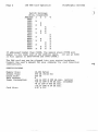
16K Ram
PolyMorphic
Systems
460 Ward [Jive Santa Barbara Califomia 93111 (805) 967-2351
·C)
This manual is PolyMorphic Systems part no. 810119.
Copyright 1977, · Interactive Products Corporation.
Card
Revision C
'Page 1
16K RAM Card Operation
PolyMorphic Systems
The PolyMorphic Systems 16K RAM card provides 16,384 bytes of
read/write storage. The card uses proven 4K dynamic RAM chips
and provides "transparent" refresh circuitry onboard (no wait
states). Each card has been tested for 72 hours before
shipment. This includes 48 hours of GALPAT and checkerboard
testing at high temperatures with no errors. This card should
provide years of trouble-free service in your 8080-based S-IOO
system.
THEORY OF OPERATION
Refresh cycles are i~serted during the T4 state of the Ml cycle
of the 8080 central processor or during a hold or halt state of
more than 15 cycles. Memory read cycles are initiated by the
coincidence of the phase 1 clock, PSYNC, and 007 (MREAD staus).
Write cycles are initiated by the leading edge of MWRITE.
If the card is used with systems using DMA (Direct Memory
Access), the DMA controller must provide the proper status bits
on the DO bus during SYNC time. The bus timing must match that
of an 8080 processor. Contact the manufacturer or distributor
of the DMA controller before attempting to use the 16K RAM card
with a DMA device.
,ADDRESSING
Consult the user's manual for your computer to determine the
correct address for this memory card. For POLY 88 or System 88
computers, the card should be addressed just above the present
top of memory.
If your system uses only 16K cards, the first
card should be addressed at 2000B, the second card at 6000B,
and the third card at AOOOH.
The 16K RAM card may be addressed to any 4K boundary within
the 64K address space of the S-IOO bus and will occupy the next
16K bytes ofs.t orage space., (Ifaddr.essed at 2000B, the RAM will
occupy 2000-5FFFH.)
The address switches are located in the
lower left corner of the card. Up to seven switches may be
present, but only the top four are used. These switches are
numbered 1 through 4 from the top of the card. The switch
settings for various addresses ar~ given below. Rocker switches
are ON when the on or plus side of the rocker switch is pressed
down. For purposes of reference, note the numbers down one side
of the card and across the top.
These numbers indicate the addresses of the memory chips within the ~6K block. Numbers down
the side indicate byte address: row 0 on the card is addressed
in the first 4K of the block, row 1 in the next, and so on.
Numbers across the top correspond to the bits in each byte.
Column 0 contains the first bit in every byte, column 1 the
second, etc.
Page 2
16K RAM Card Operation
Switch Settings
(X=on, blank=off)
2
Address 1
3
0000
1000
X
2000
X
X
3000
X
40-00 X
X
5000
X
X
6000
X
X
7000
X
X
8000
9000
X
AOOO
X
X - X
sOOO
X
COOO
X
X
Dodo
EOOO
X
X
X
FOOO
X
X
PolyMorphic Systems
,)
4
X
X
X
X
X
X
X
X
If addressed higher than COOOH, the memory above FFFFH will
appear in the lower end of the address space.
(If set at EOOO
it will appear at EOOO-FFFFH and OOOO-lFFFH.)
The RAM card may now be plugged into your system backplane.
Consult the user's manual for your computer for card insertion
instructions.
SPECIFICATIONS Memory Size:
Access Time:
Cycle Time:
Wait States:
Power Consumption:
Card Size:
16,384 Bytes
375 nS (from 01)
525 nS
o
+16 to 20V @ 200 rnA max. (active)
_ +IEi to 20V @ 90 rnA max. (standby)
+8 to 10V @ 600 rnA max.
-16 to 20V @ 24 rnA max.
5.5 n x Ion