1
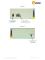
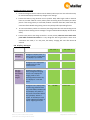
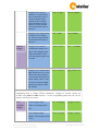
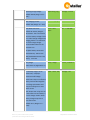
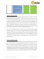
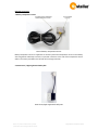
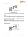
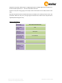
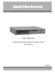
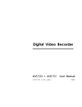
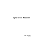
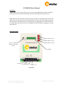
CC PWM HV User’s Manual
Introduction
Congratulations! You are the proud owner of one of the best PWM charge controllers available in
India. Please read this manual carefully before installing and operating the charge controller.
PWM charge controller model HV is advanced charge controllers for 96v battery banks and provide
maximum current up to 20 Amps. These charge controllers can work with Solar Photo Voltaic Panels
with wide power and voltage range. A three stage battery charging algorithm is implemented which
can charge battery with precise current and voltage to achieve fast battery charging yet ensuring
long battery life.
Product description
Increment button
Menu/Next button
Decrement button
LED to indicate
battery charging
status
LCD Display
PV +ve
PV -ve
Battery +ve Battery -ve
Front View
Note: For product enhancement, product
parameters can be changed without notice.
©Systellar Innovations 2014
Left Side View
For connecting
external Battery
temperature
sensor(Optional
For system
calibration only. Do
not connect anything
Right Side View
Power Saver / Night
Light Relay
Connector
(Optional Accessory)
Note: For product enhancement, product
parameters can be changed without notice.
©Systellar Innovations 2014
Installing the Charge Controller
1. Install the Charge Controller indoors near the battery bank at eye level. This will make it easy
to read the LCD display and make any changes in the settings.
2. Connect the battery using minimum 4 mm sq cables. Keep cable length small to minimize
losses in the cable. Observe correct polarity while connecting wires from battery and Solar
panels. If the wrong polarity is connected, the Batt. connection fault LED / Solar Panel (SP)
connection fault LED will start glowing. Correct the polarity before proceeding further.
3. As soon as the battery cables are connected, the Charge Controller will start working and its
display will start showing various messages. The green LED beside LCD display will also blink
slowly
4. Connect solar panel to the charge controller in correct polarity. Take care not to touch solar
panel cable ends with bare hand. It is very dangerous and will give electric shock. Once
connections are made, if it is day time, the battery charging will start after about 30
seconds.
LCD Display Messages*
LCD line 1
Initial display
messages:
DAY time
messages
when battery
is being
charged
LCD line 2
Message 1: Company name. In
case the system is uncalibrated,
line 2 displays “Sys Uncalib”
Systellar
Innovations
Message 2: Line 1 displays the
CC Model and line 2 the
software version
CC-PWM-HV
Sw ver. 1.02
Message 1: Line 1 displays
Battery voltage and charging
current. Line 2 displays the
charging mode. In case
Equalizing mode has been set,
line 2 displays ‘E’ in the last
column.
Batt:95.4V10.2A
Boost Chg
Message 2: Line 1 displays ‘Day’
and the energy collected from
solar panels today in KWHr units.
Line 2 displays relay status. If
Relay is set to be used as Power
Saver it displays “PSaver is
On/Off”. In case Relay is set to
be used as Night Light Switch, it
displays “Night Light:On/Off
DAY
Note: For product enhancement, product
parameters can be changed without notice.
02.30Hr
p.Saver:Off
©Systellar Innovations 2014
Night time
messages
Message 3: Line 1 displays
temperature. In case optional
battery temperature sensor is
installed, it displays battery
temperature else it displays
ambient temperature. Line 2
displays the energy collected
from the solar panels today in
KWHr units
Temp: 33 deg C
Total:0.230KWHr
Message 4: Line 1 displays Solar
panel power. Line 2 displays
‘Day’ and the energy collected
from the solar panels today in
KWHr units
Power 1200W
Day:0.230KWHr
Message 1: Line 1 displays
present Battery voltage. Line 2
displays “Nite” (Night) and the
energy collected by the solar
panels during the day which has
just ended.
Batt: 95.4V
Message 2: Line 1 displays “Nite”
(Night) and the time in hr. Line 2
displays relay status. If Relay is
set to be used as Power Saver it
displays “PSaver is Off”. In case
Relay is set to be used as Night
Light Switch, it displays “Night
Light: On/Off”
Nite: 5:46 hrs
Nite:
1.526KWHr
Night Switch: On
PROGRAMMING MODE: By pressing NEXT button for 2 sec, you can enter the
programming mode to change various parameters. Changes to current values can
be made using INCR and DECR buttons. To exit programming mode wait for 20 sec
without pressing any button
Adjust
Parameters
messages
End of Charging Voltage:
End of Charging
Voltage: 113.6V
Trickle Charging
Voltage: 110.4V
(Default: 113.6, Range:108V –
116V )
Trickle Charging voltage:
(Default: 110.4V, Range: 105.5V
– 112V )
Note: For product enhancement, product
parameters can be changed without notice.
©Systellar Innovations 2014
Equalizing Charge voltage:
Equalizing Chg
Voltage: 116.8v
Max. Charging
Current: 20A
Float Hold
Time:
Min. 5-150:030
Relay Usage:
0 Psvr,1 NitSw:1
Power Saver Off
Voltage: 92v
(Default:116.8V, Range: 112V –
118V )
Max. Charging current:
(Default: 20A, Range: 5A – 20A)
Float Mode Hold Time:
Default: 30 minutes, Range 5 –
150 minutes. This is the time for
which the battery voltage is held
at its end of charge voltage while
charging, before it is reduced to
the trickle charge voltage.
Recommended values for this
parameter are:
Flat plate battery: 60 minutes
Tubular battery: 150 minutes
SMF (Sealed Maintenance Free)
Battery: 5 minutes
Relay Usage:
(Power Saver: 0, Night Switch: 1)
In case Relay usage is set as
Power saver, it displays:
Power Saver Off Voltage:
Power saver relay turns off when
battery has been discharged to
this voltage. Also Power saver
relay turns off approx. 2 hours
before sunset.
Note: Power saver relay turns on
2 hours after sunrise if battery is
in trickle charge mode or when
battery voltage is equal to or
more than 13.5V.
(Default:11.5V, Range: 11.2 –
11.8V)
Note: For product enhancement, product
parameters can be changed without notice.
©Systellar Innovations 2014
In case Relay usage is set as
Night Light Switch, it displays
messages as shown here. Code 1
is for Dusk to Dawn operation of
the night switch and 2 – 14
Number of hours On after dusk
(Default: 4)
Night Light Sw:
1D-D 2-14 Hrs:04
.
Setting Equalizing charging mode:
When several batteries are connected in series (like 96v battery bank), it is useful to “overcharge”
the battery bank for a limited period of time once every month. It helps in equalizing the charge in
all the cells of the battery bank by bringing them to full charge. The electrolyte in the batteries is also
homogenised by agitation during gassing at the time of “overcharge”. In Systellar PWM HV charge
controller, equalizing charge can be set by pressing the NEXT key twice in quick succession. To
confirm that equalization charging mode has been set, check the day time display message 2. If
equalizing mode is set, ‘E’ is displayed in the last column. In case NEXT key is pressed twice in quick
succession, when equalizing mode is already set, the equalization mode is reset.
Note that when equalization mode is set, it does not go to equalization mode immediately.
Equalization charging is the last leg of battery charging. In equalizing charging mode, instead of
stopping the battery voltage at “end of charge” voltage, the system will allow the battery to go up to
“Equalizing Charge voltage” and it will maintain it there for a total period of 60 minutes. Once this
time period is over, the battery will go into “Trickle charging mode” and equalizing mode will be
automatically reset.
Setting programmable parameters
To enter “Adjust Parameter” mode, keep the NEXT key pressed for 2 seconds. It will turn on the back
light of the LCD and display the first parameter with its present value. To increase the value, press
INCR key. To decrease the value, press DECR key. Note that the value of the parameter will not go
beyond its preset limits. When NEXT is pressed, the displayed value of the parameter is written in
the MEMORY and the display goes to the next parameter. Press NEXT key for 2 seconds to come out
of ‘Adjust parameter mode’. If no key is pressed for 20 seconds, it automatically comes out of Adjust
parameter mode. Note that in this case, the value of the last parameter is not written in MEMORY.
Note: For product enhancement, product
parameters can be changed without notice.
©Systellar Innovations 2014
Optional Accessories
1. Battery Temperature sensor
External Battery Temperature Sensor
Battery temperature sensor is supplied as an accessory. Paste the temperature sensor on the battery
side using double sided tape. Insert the 4 pin RJ11 connector at the end of the temperature sensor
cable in the socket provided on the left side of the charge controller.
2. Power Saver / Night Light Switch Relay box:
Power Saver/Night Light Switch Relay Box
Note: For product enhancement, product
parameters can be changed without notice.
©Systellar Innovations 2014
For use as power saver:
Power Saver Connection Diagram
Program the parameter ‘Relay usage’ to 0 (Power Saver). Set appropriate Power Saver Off voltage. If
you want to use maximum solar energy set this voltage nearer to 89.6V. However if you want to
minimize the possibility of battery getting discharged (in case of grid supply failure) then set it nearer
to 94.4V
Inside the relay box the tag going to the output socket should come from the N/C contact of the
relay. This will cause the mains supply to the inverter to be cut when relay is On.
Connect the power plug of the relay box in a power socket. Connect inverter mains cord to the
socket provided on the Relay box. Connect the 2 pin PV connector to the relay drive output
connector on the right side of the charge controller.
Now when the battery charge voltage is more than 110.4, the relay will turn on. This will cut-off the
mains supply to the inverter and thus save electricity. Note that in this condition, the load connected
from the inverter will be driven by the battery while the battery is being charged by the solar panels.
For use as Night Light Switch:
Night Light Switch Connection diagram
Note: For product enhancement, product
parameters can be changed without notice.
©Systellar Innovations 2014
Program the parameter ‘Relay usage’ to 1 (Night Light switch). Set Night Light switch parameter to 1
for dusk to dawn operation or 2 – 14 hours of operation after dusk.
Inside the relay box the tag going to the output socket should come from the N/O contact of the
relay.
Now the relay will be turned on at dusk and remain on till dawn or for number of hours as set in the
parameters. When the relay is on, the night light connected on the socket of the relay box will be
supplied power through the relay.
Technical specifications
Technology
PULSE WIDTH MODULATION
Battery bank
voltage
96V
Maximum
charging current:
20 Ampere
Appropriate solar
panel voltage:
152-168 Volts
Idle current from
battery (typical)
11 mA
Deep discharge
protection
system shut off
voltage
Note: For product enhancement, product
parameters can be changed without notice.
84V
©Systellar Innovations 2014