1
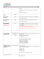
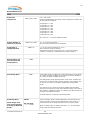
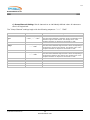
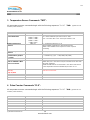
1 Brultech Research Inc GEM Commands, Packet Info and API 3/5/2012 Commands: All GreenEye commands are executed beginning with the escape sequence “^^^”. Once the GEM receives these three characters, it pauses its normal operation and listens for a valid command sequence. These commands are broken into groups: SYS system RQS request Cxx channel TMP temperature PLS pulse counter API data request 1. System “SYS” commands are used to read or modify parameters which apply to the entire system. 2. Request “RQS” commands provide the ability to read the current settings. 3. Channel “Cxx” commands allow setup of parameters relating to any of the 32(48) power monitoring channels. 4. Temperature “TMP” commands are used for setting up the temperature sensor parameters. 5. Pulse “PLS” commands are used to setup the pulse counter parameters. 6. API data “API” gets monitored data. Typically used for “polling” data when realtime packets are not used. © Brultech Research Inc 1 www.brultech.com 2 Brultech Research Inc GEM Commands, Packet Info and API ....................................................................................... 1 Commands: ....................................................................................................................... 1 1. System Commands “SYS”: ......................................................................................... 3 2. Channel Commands “Cxx”: ......................................................................................... 12 3. Temperature Sensor Commands “TMP”: .................................................................... 14 4. Pulse Counter Commands “PLS”: .............................................................................. 14 5. Request Information Commands “RQS”: .................................................................... 16 6. Data Polling API “API”: ............................................................................................ 20 7. Commands using HTTP GET method: ........................................................................ 22 © Brultech Research Inc 2 www.brultech.com 3 Brultech Research Inc 1. System Commands “SYS”: All System Commands begin with the following sequence: “^^^SYS” (quotes are not included, cases sensitive) Action RealTime “ON” Command Description “_ON” Causes the GEM to start sending real-time packets based on the user selected packet format and interval. Ex: Sending “^^^SYS_ON” GEM responds with _ON and begins sending the selected packet format after the packet send interval time has elapsed. RealTime “OFF” “OFF” Causes the GEM to stop sending real-time. If you are sending this command remotely, you should enable the “keep alive” pulse so that the GEM doesn’t lose TCP/IP connection with the server. Ex: Sending “^^^SYSOFF” GEM responds with OFF Set Packet Format “PKT”<xx> xx = 00 to 99 The value sent must be two numeric characters long. This means that a value such as “2” should be sent like this: “^^^SYSPKT02” Notice the leading zero padding. GEM responds with “PKT” if executed. The packet formats are described in the GEM’s Packet Format manual. Set Packet Send Interval “IVL” <xxx> xxx = 001 to 256 This must be three numeric characters long. GEM responds with “IVL” once executed. The value represents the number of seconds between each packet send. Realtime must be enabled (_ON) for the packets to be sent. Set Packet Chunk Size “PKS”<val><CR> <val> is a numeric value between 80 and 65000 A carriage return (CR) is required at the end of the command. This parameter sets the number of bytes to be sent in each chunk. Since the GEM’s packet size can be fairly large, the packet sometimes need to be broken into small sections (chunks) with slight pauses (milliseconds) between each transmission in order not to surpass the throughput of certain communicating devices. © Brultech Research Inc 3 www.brultech.com 4 Brultech Research Inc Ex: ^^^PKS240<CR> will cause the packet data to be sent in chunks of 240 bytes. The GEM responds with PKS Set Packet Chunk Interval Time “PKI”<val><CR> <val> is a numeric value between 1 and 65000 A carriage return (CR) is required at the end of the command. The GEM responds with PKI Set Max Buffer Size “BFF”<val><CR> <val> is a numeric value between 10 and 1700 A carriage return (CR) is required at the end of the command. The GEM responds with BFF Enable Wifi Hardware Flow Control Affecting Packet Send Requires RN-171 firmware version 1.44 or greater “FL1”<x> <x> = 0 for disabled or 1 for enabled. Make sure RN-171 is set for “set uart flow 1”. Option 2 uses the RTS line. This option is implemented to prevent buffer issues with the Wifly module. The GEM responds with FL1 OR “Hardware Flt” which signifies that the GEM is not configured for Wifi module. Enable Zigbee Flow Control (COM2). “FL2”<x> <x> = 0 for disabled or 1 for enabled. Make sure that XBee flow control is enabled ATD71 (CTS). This option applies to realtime packet data transfer from the process buffer only. Commands are issued regardless of flow status. This flow control also stops data from being sent to the Wifi module or other COM1 communication module The GEM responds with FL2 OR “Hardware Flt” which signifies that the GEM is not configured for XBee module. PT Type “TPT” <xxx> xxx= 001 to 255 Value must be three numeric characters long. GEM responds with “TPT” This value is a constant based on the Potential Transformer’s (PT) voltage ratio. A value for this constant is chosen so that the GEM displays the proper AC line voltage. If the GEM displays 116V when a multimeter measures 118V at the power line, this value may be increased slightly to cause the GEM to display 118V. See manual for more information. © Brultech Research Inc 4 www.brultech.com 5 Brultech Research Inc PT Range “VRG” <xx> xx= 00 to 10 Value must be two numeric characters long. GEM responds with “VRG” This parameter works in conjunction with the “PT Type” described above. The interpreted voltage is doubled every time the value is reduced by one. For example: Range = 3 Displayed voltage = 117.0 V Range = 2 Displayed voltage = 234.0 V Refer to the GEM User’s Manual for more details. Reset a Specific Pulse Counter “RSP” <x> x = 1 to 4 <x> is a numeric value representing the pulse counter channel to be reset. The reset value is zero. Each counter channel is 3-bytes long, therefore can count to 16,777,215 pulses. GEM responds with “RSP” if executed. Reset All Pulse Counters “RSTP” Reset All Counters “RSTA” Zeroes all counters: Channel 1 to 48 watt-second All pulse counters Seconds counter GEM responds with “RSTA” after execution. Reset Seconds Counter “RSTS” Zeroes the seconds incremental counter. This counter increments every second as long as the system is monitoring. Resets all four pulse channel counters to zero. GEM responds with “RSTP” if executed. GEM responds with “RSTS” It is used along with watt-second values to calculate Watt. Refer to GEM manual. Reset the WattSecond counter for a specified channel. “RSTC” <xx> xx = 01 to 48 <xx> must be a two character value. GEM responds with “RSTC” This command zeroes the watt-second counter for the specified channel. Absolute and Polarized counters are both reset. Set the Line Frequency to 50Hz or 60Hz © Brultech Research Inc HZ<x> <x> = “0” (60Hz) OR “1” (50Hz) GEM responds with “HZ” 5 www.brultech.com 6 Brultech Research Inc Set Date and Time “DTM”<yy,mm,dd,h h,mm,ss><CR> Set the date and time of the GEM. For the most part, this date clock is not required. It is there for future use. Ex: “DTM12,08,23,13,30,28”<CR> will set the GEM for August 23 rd, 2012 1:30:28 pm GEM responds with “DTM” Bootload COM processor Bootload Engine processor Set the HTTP post URL Wait 500 ms after B87 response “URL”<url><CR> <url> is the URL text such as http://mysite.com The last byte must be a CR to indicate the end to the URL data. The URL text is limited to 63 characters. GEM responds with “URL” Set the HTTP post URL extension “URE”<url ext><CR> <url ext> is the URL extension text such as /mycode.php The last byte must be a CR to indicate the end to the URL extension data. The URL extension text is limited to 63 characters. GEM responds with “URE” Set Data Host Token/Key1 URT<token><CR> <token> is the assigned token from the data hosting site. Max 63 characters. The last byte must be a CR to indicate the end the token string. The token string is limited to 63 characters (not including the CR). GEM responds with “URT” Set Additional Post © Brultech Research Inc “URK”<x><key> <x> is the key number from 2 to 8 6 www.brultech.com 7 Brultech Research Inc Keys <CR> <key> is the assigned key from the data hosting site. Max 31 characters. The last byte must be a CR to indicate the end the token string. The token string is limited to 63 characters (not including the CR). GEM responds with “URK” Set Data Host Device Node URN<node><CR> <node> is the assigned token from the data hosting site. Max 63 characters. The last byte must be a CR to indicate the end the token string. The token string is limited to 63 characters (not including the CR). GEM responds with “URN” Reset XBee Module “ZBR” Reset Wifi Module “RSW” Wifi Auto Reset Interval “WAR”<x><CR> Automatically sends a reset pulse to Wifi module after “x” seconds if data has not been received from COM1 port. If x=0 then this feature is disabled Valid Range: 30 to 255 seconds If a value between 1 and 29 is entered, the value of 30 will automatically be used. The last byte must be a CR to indicate the end. This feature has been implemented to deal with issues of third party hardware. If the communication module locks up or stops responding, this option causes a reset to restart the module, restoring communication. Refer to GEM manual for more information. GEM responds with “WAR” Wifi No-HTTPResponse Reset Interval “WRR”<x><CR> Automatically sends a reset pulse to Wifi module after “x” number of missing response after sending an HTTP “GET”, “POST” or “PUT. Used in cases where the Wifi module may have locked up. Valid Range: 2 to 255 missing responses The last byte must be a CR to indicate the end. This feature has been implemented to deal with issues inherent of third party hardware. If the communication module locks up or stops responding, this option causes a reset to restart the module, restoring communication. This method is preferred over the “WAR” method © Brultech Research Inc 7 www.brultech.com 8 Brultech Research Inc when sending packet data using HTTP GET or PUT method. Refer to GEM manual for more information. GEM responds with “WRR” ZigBee Auto Reset Interval “ZAR”<x><CR> Automatically sends a reset pulse to Wifi module after “x” seconds if data has not been received from COM1 port. If x=0 then this feature is disabled Valid Range: 30 to 255 seconds If a value between 1 and 29 is entered, the value of 30 will automatically be used. The last byte must be a CR to indicate the end. This feature has been implemented to deal with issues of third party hardware. If the communication module locks up or stops responding, this option causes a reset to restart the module, restoring communication. Refer to GEM manual for more information. GEM responds with “WAR” ZigBee No-HTTPResponse Reset Interval “ZRR”<x><CR> Automatically sends a reset pulse to Wifi module after “x” number of missing response after sending an HTTP “GET”, “POST” or “PUT. Used in cases where the Wifi module may have locked up. Valid Range: 2 to 255 missing responses The last byte must be a CR to indicate the end. This feature has been implemented to deal with issues inherent of third party hardware. If the communication module locks up or stops responding, this option causes a reset to restart the module, restoring communication. This method is preferred over the “WAR” method when sending packet data using HTTP GET or PUT method. Refer to GEM manual for more information. GEM responds with “WRR” Set Installed Hardware/Module “HDW”<x><CR> No Modules x = 0 Wifi only: x = 1 Zigbee only x = 2 Wifi and Zigbee x = 3 Wiznet only COM1 x = 4 Wifi and Wiznet (COM2) x = ? Informs GEM’s processor as to which hardware communication module(s) is installed. If this value is not configured, the green system LED will flash every © Brultech Research Inc 8 www.brultech.com 9 Brultech Research Inc second. This setting is important to reduce battery drain during power outages. GEM responds with “HDW” Wifi Baud Reset to 19200 “WBR” Re-Boot COM Processor “RBC” Re-Boot Engine1 Processor “RBE” Master Polyphase ON/OFF Setting “PH”<x> This command restarts the main processor. Used for debugging. GEM responds with “RBC” Resets the power engine processor. Generally not required. GEM responds with “RBE” (New 09/10/12) X = 0 Polyphase is OFF all phases assume phase A regardless of phase settings. X= 1 Polyphase is ON all channels are assigned the user defined phase setting. X= 2 Three-phase delta with 30degree offset X = 3 Single Phase with CT phase compensation based on CT setting GEM responds with “PHx” where “x” is the selected value Enable Channels to be included in the HTTP PUT packet “EPC”<xxx>,<xxx> ,<xxx>, <xxx>,<xxx>,<xxx ><CR> xxx = 000 to 255 Six bit mapped bytes sets which of the 48 channels will be sent with the HTTP post. First value = channels 1 to 8 Second value = channels 9 to 16 …… and so on Ex: EPC007,001,128,000,001,000<CR> 007(1-8): chan 1,2 and 3 are enabled 001(8-16): chan 9 enabled 128(17-24): chan 24 enabled 000(25-32): none enabled 001(33-40): chan 33 enabled 000(41-48): none enabled Enable Pulse Counters included in the HTTP PUT packet “EPP”<xxx><CR> xxx = 000 to 015 Single bit mapped bytes sets which of the 4 pulse counting channels will be sent with the HTTP post. Counter1 Counter2 Counter3 Counter4 = = = = bit0 bit1 bit3 bit4 Ex: value 004 = CNTR 3 enabled for POST © Brultech Research Inc 9 www.brultech.com 10 Brultech Research Inc Enable Post Temperature “EPT”<xxx><CR> xxx = 000 to 255 Single bit mapped bytes sets which of the 8 temperature channels will be sent with the HTTP post. Temperature Temperature Temperature Temperature Temperature Temperature Temperature Temperature 1 2 3 4 5 6 7 8 = = = = = = = = bit0 bit1 bit2 bit3 bit4 bit5 bit6 bit7 Ex: value 017 = T1 and T5 enabled for POST Set Max Number of Channels To Be Used Set Number of ThingSpeak Block “CMX”<xx><CR> “TSB”<x> Read and Store SN from Bootload (Get Serial Number) “GSN” Enter Bridge Mode “BR1” X = 01 to 48 (two characters) Prevents from processing un-used channels. <x> is the number of blocks from 1 to 8 Each TS blocks contain 8 channels. Each block has its own unique post “Key”. The first key (block1) resides in “Token/Key1”. Subsequent keys reside in Key2-8. Links COM1 directly to COM2 and is baud independent. The serial port or module connected to COM1 has a crossover connection directly to any device on COM2 or COM2’s serial port. The GEM pauses regular processes while in this mode. The date-time clock is also not functional at this time, therefore if the realtime clock is used for any reason, it should be updated after exiting bridge mode. This function is very handy for accessing installed communication devices via a serial port or other communication module. This mode is also useful for upgrading firmware or configuring an XBee module (for example) using COM1 serial port. A special sequence is required to exit bridge mode. Exit Bridge Mode NOTE: NOTE: Bridge mode may also be exited by pressing the GEM’s PB briefly. Do not send “^^^” <SYS> © Brultech Research Inc Since the bridge1 mode is baud independent, the command to exit from this mode must also be baud independent. For this reason, a timed sequence of any single character is sent to exit this mode. When in bridge mode, the System LED will be ??? . To exit bridge1 mode, send the following sequence: 10 www.brultech.com 11 Brultech Research Inc Only send the sequence described in the paragraph (right) Factory Preset “FP”<x> <any <any <any <any <any single single single single single character> character> character> character> character> pause pause pause pause 1.75 second 1.75 second 750 millisecond 750 millisecond <x> is 0-3 0 = no com modules installed 1 = Wifi module installed 2 = XBee module installed 3 = Both modules installed 4 = Wiznet Only on COM1 Presets all default values and sets up the hardware settings including flow control. © Brultech Research Inc 11 www.brultech.com 12 Brultech Research Inc 2. Channel Commands “Cxx”: a) Individual Channel Settings are commands that affect only the specified channel. One command is required for each channel. b) All Channel Settings will set all of the channels to a given value c) Group Channel Setting is used to give each channel with a unique value, however the values for all 48 channels are sent in a structured block to speed up the process. c) Individual Channel Settings: Sets a given channel to a given value. All individual channel settings begin with the following sequence: “^^^” “Cxx”, where “xx” is the channel number 01 to 48. Action Set channel CT Type Set channel CT Range Command Description TYP <xxx> xxx = 001 to 255 RNG <x> Set channel Phase PH<x> Set channel Phase Compensation PC(x) x = 0 to 9 x = A or B or C X = 0,1,2 0 = no phase compensation 1 = 4 degrees compensation 2 = 8 degrees compensation (Added Sept 10,2012) Toggle channel polarity (revised Apr 22, 2012) “^^^CH”<p><xx> <p> is “0” or “1” polarity <xx> is two character channel number b) All Channel Settings: Sets all channels to a common setting defined by a single value. The “All Channel” settings begin with the following sequence: “^^^” “CHE”. Action Set All channel CT Type Set All channel CT Range Command TYP <xxx> RNG <x> Set All channel Phase PHx Set All Channel Pol 0 (default) Set All Channel Pol 1 POL0 © Brultech Research Inc Description xxx = 001 to 255 x = 0 to 9 x = A or B or C POL1 12 www.brultech.com 13 Brultech Research Inc c) Group Channel Setting: Set all channels to an individually defined value. All values are sent in a single block. The “Group Channel” settings begin with the following sequence: “^^^” “CHG”. Action Command Description Set CH1 to CH48 CT Type TYP <xxx>,<xxx>, <xxx>, ……. <CR> xxx = 001 to 255 Send 48 comma delimited 3-character values corresponding to the desired CT type for each channel. The carriage return <CR> completes the block. A response is echoed “OK” or “ER” Set All channel CT Range RNG <x>,<x>,<x>, …….. <CR> x = 0 to 9 Send 48 comma delimited single character values corresponding to the desired CT range for each channel. The carriage return <CR> completes the block. A response is echoed “OK” or “ER” PH<x>,<x>,<x>, ………. <CR> x = A or B or C Send 48 comma delimited single character values corresponding to the desired CT phase for each channel. The carriage return <CR> completes the block. A response is echoed “OK” or “ER” Set All channel Phase © Brultech Research Inc 13 www.brultech.com 14 Brultech Research Inc 3. Temperature Sensor Commands “TMP”: All temperature sensor commands begin with the following sequence: “^^^” “TMP” (quotes are not included, cases sensitive) Action Save Temperature Sensor ROM code Enable Temperature Channel Disable Temperature Channel REMOVED! Set Resolution (9,10,11 or 12 bit) Read then Write ROM code for SINGLE 1-Wire Device connected. Set Temperature Units (C or F) Sept 12,2012 Command Description “ROM <c>, <val1> <val2> <val3> <val4> <val5> <val6> <val7> <val8><CR> “EN”<x> c = temperature channel number “1” to “8” val = three character byte value “000” to “255” val1 = the value after <val> is the byte number 1 to 8 x = Temperature Channel 1 to 8 When enabled, temperature is processed and read. NOTE: Leave disabled if not required to reduce required processing. “DS”<x> x = Temperature Channel 1 to 8 R<x><r> x = Temperature Channel 1 to 8 r = resolution (0,1,2,3 = 9bit,10bit,11bit,12bit) “ROW”<x> x = Temperature Channel 1 to 8 NOTE: Only one 1-wire device may be connected to the bus when using this command. Reads the ROM code of the connected 1-wire device and saves it to the temperature channel indicated by the value of <x>. “DGC” or “DGF” DGC sets to Celsius DGF sets to Fahrenheit 4. Pulse Counter Commands “PLS”: All temperature sensor commands begin with the following sequence: “^^^” “PLS” (quotes are not included, cases sensitive) Action Enable Pulse Counter Disable Pulse Counter © Brultech Research Inc Command “EN”<x> “DS”<x> Description x = Counter number 1 to 4 x = Counter number 1 to 4 14 www.brultech.com 15 Brultech Research Inc © Brultech Research Inc 15 www.brultech.com 16 Brultech Research Inc 5. Request Information Commands “RQS”: All data Request commands begin with the following sequence: “^^^” “RQS ” Action Read all settings Command “ALL” Description Response: “ALL” <CRLF> Then sends Hex values comma delimited: - - © Brultech Research Inc 1 byte (spare) 48 bytes channel option 48 bytes CT types (ch1 to ch48) 24 bytes CT range (One nibble/channel. Two nibbles/byte.) ex: First CT range byte = 0x23, CH1 CT range = 3 and CH2 CT range = 2 1 byte = PT type 1 byte = PT range 1 byte = packet format selection 1 byte = packet send interval 1 byte: Wifi Auto Reset Timer Value (“0” = off) 1 byte:Wifi Missing Resp Rst Value (“0” = off) 1 byte: Wifi Options 1 byte: Xbee Auto Reset Timer Val (“0” = off) 1 byte: Xbee Missing Resp Rst Val (“0” = off) 1 byte: XbeeWifi Options 1 byte: Primary COM port (not yet implemted) 48 bytes = packet options / channel 1 byte = counter options bits 0 to 3, set for enabled (selects if included in certain packet formats) 1 byte = temperature enable 8bits, one per temperature channel (selects if included in certain packet formats) 8 bytes = Temperature 1 ROM code 8 bytes = Temperature 2 ROM code 8 bytes = Temperature 3 ROM code 8 bytes = Temperature 4 ROM code 8 bytes = Temperature 5 ROM code 8 bytes = Temperature 6 ROM code 8 bytes = Temperature 7 ROM code 8 bytes = Temperature 8 ROM code 1 byte = Temperature channel enabled to be converted and read. 1 byte = Additional 1-Wire device options 1 byte = Hardware Modules Installed (required to reduce battery consumption) 1 byte = Maximum channels processed. 48 bytes = reserved for future 8 bytes = System Settings 6 bytes = bitwise selects which of the 48 channels sent during an HTTP PUT 1 byte = bitwise selects which of the 4 pulse counter channels sent during an HTTP PUT . 1 bytes = bitwise selects which of the 8 temperature channels sent during an HTTP PUT 2 bytes = General packet options 1 byte = NET metering options (bi-directional counter? ) 2 bytes = Chunk size 1 byte = Enabled Pulse counters… which counters are processed. Others..???? 16 www.brultech.com 17 Brultech Research Inc --------- total ??? (was 374) bytes End with <CRLF> Read all CT Types “ATP” Response: Hex values comma delimited Packets sent: Read all CT Ranges “ARG” 48 comma delimited Hex values <CRLF> carriage return (ascii 13d,10d) Response: Hex values comma delimited Data sent: 24 comma delimited Hex values <CRLF> carriage return (ascii 13d.10d) Each range is represented by a single nibble of each Hex value. The LSB nibble represents the odd channels and MSB nibble the even channels. For example: Hex values: 12,32,34,45…….. would represent CH1 CH2 CH3 CH4 CH5 CH6 CH7 CH8 Read All channel Options “AOP” range range range range range range range range = = = = = = = = 2 1 2 3 4 3 5 4 Response: Comma delimited Hex values. One value for each channel. The “phase” setting is part of this byte. Packets sent: Read Channel Phase Setting “PH”<xx> 48 comma delimited Hex values <CRLF> carriage return (ascii 13d,10d) <xx> is 01 to 48 channel value Responds with “A”, “B” or “C” Read Realtime Status “RTL” Responds with “OFF” or “ON” followed by <CRLF> Read Realtime Send Interval “ITV” Responds with a single hex value representing 0 to 255 seconds followed by <CRLF> Read Realtime Packet Format “RTF” Responds with a single hex value representing format value followed by <CRLF> Read Temperature ON/Off Status “TST” Responds with “xxxxxxxx” where x = 0 or 1 (off/on) followed by <CRLF> Ex: 00010100 temp channel 3 & 5 enabled © Brultech Research Inc 17 www.brultech.com 18 Brultech Research Inc Read Pulse ON/Off Status “PST” Read Packet Chunk Size “PKS” Read Packet Chunk Interval Get Max Buffer Size “PKI” “BFF” Read Specified Channel CT Type and Range “Cxx” Read PT Type and Range “RPT” Read Hertz Setting Read 8 Temperature ROM byte setting Read Max Channel Setting Master Enable Polarized WS counters for NET metering “HZ” “RTR”<x> “CMX” “ENM”<x> Read ThingSpeak number of blocks “TSB” Read URL string Read URL extension “URL” “URE” Responds with “xxxx” where x = 0 or 1 (off/on) followed by <CRLF> Ex: 0100 pulse counter 3 enabled Responds with numeric value (two byte size) Responds with a value between 10 and 1700. This value is the maximum number of bytes to be buffered and must be set to a value greater than the packet size and chunk size. If set to great, problems may occur trying to transfer too much buffered data should a connection be lost then restored. xx= 01 to 48 Channel number Responds with two byte hex value representing CT Type and Range values <CRLF> Responds with two byte hex value representing PT Type and Range values <CRLF> Responds with 60Hz or 50Hz x = 1 to 8 Responds with 8 comma delimited hex bytes followed by CRLF A value of 1 to 48 is returned. This represents the value that the maximum number of channels to be processed is set to. .x = “0” or “1” When set to “1”, polarized ws counters are used. If NET metering is not required, set this value to zero. Future updates will provide the ability to select which channel polarized counters are enabled. Returns the number of ThingSpeak blocks. Each block contins 8 channels. <url string> Followed by CRLF <url extension string> Followed by CRLF “TE”<x> x is the temperature channel Read Wifi Auto-Reset Value Read Wifi Missing Response Counter Value “WAR” Returns Wifi Auto-Reset value “WRR” Returns Wifi Missing Response value Read Firmware Version of Master Processor “VR1” Read the firmware version for the communication processor. Ends with CRLF Read Firmware Version of Engine Processor “VR2” Read the firmware version for CH1 to CH32 engine processor. Ends with CRLF Read Firmware Version of Expansion Processor (if 16 channel expansion is present) “VR3” Read the firmware version for CH33 to CH48 engine processor. Ends with CRLF Read Temperature © Brultech Research Inc 18 www.brultech.com 19 Brultech Research Inc Request time “DTM” Read Serial Number “SRN” Read Enabled Post Channels “EPC” Read realtime clock yy-mm-dd hh:mm:ss Returns: <xxx>,<xxx>,<xxx>,<xxx>,<xxx>,<xxx> xxx = 000 to 255 Six bit mapped bytes sets which of the 48 channels will be sent with the HTTP post. First value = channels 1 to 8 Second value = channels 9 to 16 …… and so on Ex: EPC007,001,128,000,001,000<CR> 007(1-8): chan 1,2 and 3 are enabled 001(8-16): chan 9 enabled 128(17-24): chan 24 enabled 000(25-32): none enabled 001(33-40): chan 33 enabled 000(41-48): none enabled Read Enabled Post Counters “EPP” Returns bit mapped value representing the counters included in HTTP post. Read Enabled Post Temperature Channels “EPT” Returns bit mapped value representing the temperature channels included in HTTP post. © Brultech Research Inc 19 www.brultech.com 20 Brultech Research Inc 6. Data Polling API “API”: All data Request commands begin with the following sequence: “^^^” “API” Action Read Single Channel Power (Watt) Read Power for a Range of Channels (Watt) Read Single Channel Energy (WattSecond) Read Absolute for a Range of Channels (WattSeconds) Read Enabled Channels for POST Command Description “WAT”<xx> xx= Channel number 01 to 48 Numeric watt data followed by CRLF “WRG” <ss><rr> “ENR”<xx> ss = start channel (01 to 48) rr = number of consecutive channels Numeric Data sent is comma delimited. Ends with CRLF xx= Channel number 01 to 48 Numeric watt-second data followed by CRLF “EGR” <ss><rr> ss = start channel (01 to 48) rr = number of consecutive channels Numeric Watt-Second Data sent is comma delimited. Ends with CRLF “EPC” Returns six byte values. These bit-mapped values represents which channels are included during a POST Returned values are comma delimited. Read Enabled Pulse Counters for POST “EPP” Read Enabled Temperature Channels for POST “EPT” Ex: value 5 = counter 1 and counter 3 Returns single byte value 0 to 15 This bit-mapped value represents which pulse counter channels are included during a POST Ex: value 5 = counter 1 and counter 3 Returns single byte value 0 to 255 This bit-mapped value represents which temperature channels are included during a POST Ex: value 5 = temp 1 and temp 3 Read Voltage “VLT” Sends Numeric Value = Volt x 10. This value should be divided by ten to obtain one decimal point accuracy. Ends with CRLF Read Incremental Seconds Counter “SEC” Send Numeric 3-byte value. Ends with CRLF Send all recent power, temperature and counter values. “VAL” Responds with “VAL”<CRLF> Sends comma delimited numeric values. c1=<watt>,c2=<watt> ………,t1=<degrees>,t2=<degrees>,…… p1=<pulse count lsb value>, …… “END”<CRLF> The purpose of this API is to provide updated data to the setup © Brultech Research Inc 20 www.brultech.com 21 Brultech Research Inc program. Read Temperature of Specified Temperature Channel Send One Packet © Brultech Research Inc “TP”<x> “SPK” “x” is the temperature channel number. Sends using the currently selected packet format. Realtime must be OFF in order for this cmd to be functional. 21 www.brultech.com 22 Brultech Research Inc 7. Commands using HTTP GET method: All data Request commands begin with the following sequence: “^^^” Action Command Send All GEM Settings Info “RQS” “WEB” index.php/ecmEngine/gsettings/?SN=&cm=&t1=&t2=&t3=&t4=&t5=&t6=&t7= &t8=&t9= &t10=&t11=&t12=&t13=&t14=&t15=&t16=&t17=&t18=&t19=&t20=&t21=&t22 =&t23= &t24=&t25=&t26=&t27=&t28=&t29=&t30=&t31=&t32=&t33=&t34=&t35=&t36 =&t37= &t38=&t39=&t40=&t41=&t42=&t43=&t44=&t45=&t46=&t47=&t48=&r1=&r2= &r3=&r4= &r5=&r6=&r7=&r8=&r9=&r10=&r11=&r12=&r13=&r14=&r15=&r16=&r17=&r1 8=&r19= &r20=&r21=&r22=&r23=&r24=&r25=&r26=&r27=&r28=&r29=&r30=&r31=&r3 2=&r33= &r34=&r35=&r36=&r37=&r38=&r39=&r40=&r41=&r42=&r43=&r44=&r45=&r4 6=&r47= &r48=&p1=&p2=&p3=&p4=&p5=&p6=&p7=&p8=&p9=&p10=&p11=&p12=&p1 3=&p14= &p15=&p16=&p17=&p18=&p19=&p20=&p21=&p22=&p23=&p24=&p25=&p26 =&p27= &p28=&p29=&p30=&p31=&p32=&p33=&p34=&p35=&p36=&p37=&p38=&p39 =&p40= &p41=&p42=&p43=&p44=&p45=&p46=&p47=&p48=&pt=&pr=&dp=&si= SN = serial number cm = maximum channels used t = channel type r = channel range p = channel phase pt = PT Type pr = PT Range dp = device phase si = send interval © Brultech Research Inc 22 www.brultech.com 23 Brultech Research Inc © Brultech Research Inc 23 www.brultech.com