1
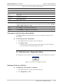
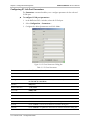
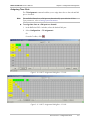
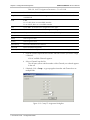
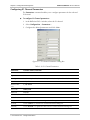
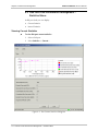
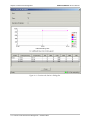
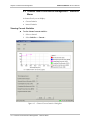
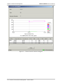
RADview/TDM
Element Management System for TDM Applications
DXC-4
© 1994–2004 RAD Data Communications
Publication 05/04
Contents
Chapter 1. Introduction
1.1 Overview of the DXC-4 Device.................................................................................... 1-1
Using the Graphical User Interface ........................................................................................ 1-2
LEDs..................................................................................................................................... 1-3
1.2 System Level Operations.............................................................................................. 1-4
1.3 Port Level Operations .................................................................................................. 1-6
Link Port Level Operation ..................................................................................................... 1-6
Control Port Level Operation ................................................................................................ 1-7
1.4 Channel Level Operations ........................................................................................... 1-7
E1/T1 Channel Level Operation ............................................................................................ 1-7
Chapter 2. Fault Management
2.1 System Level Fault Management – Fault Menu............................................................. 2-1
Displaying the Active Alarms ................................................................................................. 2-1
Clearing the Active Alarm Buffer ........................................................................................... 2-2
Displaying the System Alarm Buffer List ................................................................................. 2-3
Clearing the Alarm Buffer...................................................................................................... 2-4
2.2 Link Port Level Fault Management – Fault Menu.......................................................... 2-4
Displaying the Active Alarms for a Link Port........................................................................... 2-5
Clearing the Link Port Active Alarm Buffer............................................................................. 2-6
2.3 Link Port Level Fault Management – Diagnostics Menu................................................ 2-6
Running a Test on a Link Port ............................................................................................... 2-6
2.4 Channel Port Level Fault Management – Fault Menu ................................................... 2-8
Displaying the Active Alarms for a Channel Port .................................................................... 2-8
Clearing the Channel Port Active Alarm Buffer....................................................................... 2-9
2.5 Channel Port Level Fault Management – Diagnostics Menu ....................................... 2-10
Running a Test on a Channel Port ....................................................................................... 2-10
Chapter 3. Configuration Management
3.1 System Level – Configuration Menu ............................................................................. 3-1
Viewing and Setting System Information................................................................................ 3-1
Setting System Parameters..................................................................................................... 3-3
Polling the Agent................................................................................................................... 3-4
Resetting the Hardware......................................................................................................... 3-4
3.2 System Level – Options Menu ..................................................................................... 3-5
Configuring the Manager List................................................................................................. 3-5
3.3 Link Port Level – Configuration Menu.......................................................................... 3-7
Configuring T1 Link Port Parameters ..................................................................................... 3-7
Configuring E1 Link Port Parameters ..................................................................................... 3-9
Assigning Time Slots............................................................................................................ 3-10
3.4 Control Port Level – Configuration Menu................................................................... 3-12
Configuring Control Port Parameters ................................................................................... 3-13
3.5 Channel Port Level – Configuration Menu ................................................................. 3-14
Configuring T1 Channel Parameters .................................................................................... 3-14
Configuring E1 Channel Parameters .................................................................................... 3-15
RADview/TDM DXC-4 User’s Manual
i
Table of Contents
Chapter 4. Performance Management
4.1 System Level Performance Management – Statistics Menu ........................................... 4-1
Setting Polling Interval........................................................................................................... 4-1
4.2 Port Level Performance Management – Statistics Menu................................................ 4-2
Viewing Current Statistics...................................................................................................... 4-2
Viewing Interval Statistics ...................................................................................................... 4-4
4.3 Channel Level Performance Management – Statistics Menu ......................................... 4-7
Viewing Current Statistics...................................................................................................... 4-7
Viewing Interval Statistics ...................................................................................................... 4-8
ii
RADview/TDM DXC-4 Installation and Operation Manual
Table of Contents
List of Figures
1-1. RADview DXC-4 Window ................................................................................................... 1-2
2-1. System Level Fault Menu...................................................................................................... 2-1
2-2. All Active Alarm List Dialog Box ........................................................................................... 2-2
2-3. System Alarm Buffer List Dialog Box ..................................................................................... 2-3
2-4. Port Level Fault Menu .......................................................................................................... 2-5
2-5. Port Active Alarms List Dialog Box ........................................................................................ 2-5
2-6. Port Level Diagnostics Menu ................................................................................................ 2-6
2-7. Port Test Dialog Box............................................................................................................. 2-7
2-8. Channel Level Fault Menu.................................................................................................... 2-8
2-9. Port Active Alarms List Dialog Box for Channels ................................................................... 2-8
2-10. Channel Level Diagnostics Menu...................................................................................... 2-10
2-11. Channel Test Dialog Box .................................................................................................. 2-10
3-1. System Level Configuration Menu ........................................................................................ 3-1
3-2. System Information Dialog Box ............................................................................................ 3-2
3-3. System Parameters Dialog Box ............................................................................................. 3-3
3-4. Reset HW Dialog Box .......................................................................................................... 3-4
3-5. System Level Options Menu................................................................................................. 3-5
3-6. Manager List Dialog Box....................................................................................................... 3-6
3-7. Link Port Level Configuration Menu ..................................................................................... 3-7
3-8. T1 Port Parameters Dialog Box............................................................................................. 3-8
3-9. E1 Port Parameters Dialog Box ............................................................................................. 3-9
3-10. Link TS Assignment Dialog Box – T1 Link ......................................................................... 3-10
3-11. Link TS Assignment Dialog Box – E1 Link ......................................................................... 3-11
3-12. Group TS Assignment Dialog Box ..................................................................................... 3-12
3-13. Control Port Configuration Menu ..................................................................................... 3-12
3-14. Control Port Parameters Dialog Box ................................................................................. 3-13
3-15. Channel Level Configuration Menu ................................................................................. 3-14
3-16. T1 Channel Parameters Dialog Box ................................................................................. 3-14
3-17. E1 Channel Parameters Dialog Box .................................................................................. 3-16
4-1.
4-2.
4-3.
4-4.
4-5.
4-6.
System Level Statisitics Menu .............................................................................................. 4-1
Polling Interval Selection Dialog Box ................................................................................... 4-1
Port Current Statisitics ........................................................................................................ 4-3
Port Intervals Statisitics ....................................................................................................... 4-5
Channel Current Statisitics.................................................................................................. 4-8
Channel Intervals Statisitics............................................................................................... 4-10
RADview/TDM DXC-4 Installation and Operation Manual
iii
Table of Contents
List of Tables
1-1.
1-2.
1-3.
1-4.
1-5.
DXC-4 LEDs ........................................................................................................................ 1-3
System Management Device Mode Options........................................................................ 1-4
Link Port Management Options........................................................................................... 1-6
Control Port Management Options...................................................................................... 1-7
Channel Management Options............................................................................................ 1-7
2-1. All Active Alarm List Parameters ........................................................................................... 2-2
2-2. System Alarm Buffer List Parameters..................................................................................... 2-4
2-3. Port Active Alarms List Parameters........................................................................................ 2-5
2-4. Port Test Parameters ............................................................................................................ 2-7
2-5. Port Active Alarms List Parameters for Channels .................................................................. 2-9
2-6. Channel Test Parameters .................................................................................................... 2-11
3-1. System Information Parameters ............................................................................................ 3-2
3-2. System Parameters ............................................................................................................... 3-3
3-3. Manager List Parameters ...................................................................................................... 3-6
3-4. T1 Port Parameters............................................................................................................... 3-8
3-5. E1 Port Parameters ............................................................................................................... 3-9
3-6. Link TS Assignment Parameters – T1 or E1 Link .................................................................. 3-11
3-7. Group TS Assignment Parameters....................................................................................... 3-12
3-8. Control Port Parameters ..................................................................................................... 3-13
3-9. T1 Channel Parameters ..................................................................................................... 3-15
3-10. E1 Channel Parameters .................................................................................................... 3-16
4-1.
4-2.
4-3.
4-4.
iv
Port Current Statisitics Parameters ....................................................................................... 4-4
Port Intervals Statisitics Parameters ...................................................................................... 4-6
Channel Current Statisitics Parameters................................................................................. 4-8
Channel Intervals Statisitics Parameters.............................................................................. 4-11
RADview/TDM DXC-4 Installation and Operation Manual
Chapter 1
Introduction
This chapter provides an overview of the DXC-4 device and the RADview DXC-4
user interface.
1.1 Overview of the DXC-4 Device
The DXC-4 is a standalone unit, used for protected monitoring of T1/E1 digital
transmission lines. Protected monitoring is performed by connecting each pair of
the T1/E1 link, from its protected monitoring point (PMP) to a receiver in the
DXC-4. The DXC-4 can be equipped with up to 8 receivers, providing protected
monitoring for 8 T1/E1 links. The DXC-4 is able to groom up to a full 24 (for a T1
link) or 31 (for an E1 link) DS0 timeslots over a single link towards a central
location. Compliance with the ITU-T G.772 specifications allows the DXC-4 to
groom the full number of timeslots on the link with no impedance of the
transmitted digital signal, allowing the Telecom Carrier to monitor and analyze
infrastructure performance without having to dispatch a field technician or
equipment to a remote location.
Using the Graphical User Interface
Figure 1-1. RADview DXC-4 Window
The RADview DXC-4 window provides a dynamically updated graphical
representation of the DXC-4 front and rear panels, allowing you to monitor and
manage DXC-4 operations. The window includes port interfaces and their
operational and communication statuses, as well as the device’s LED indicator
statuses.
Overview of the DXC-4 Device
1-1
RADview/TDM DXC-4 User’s Manual
Chapter 1 Introduction
Menu Bar
The menu bar includes the following pull-down menus: Configuration, Fault,
Diagnostics, Options, and Help. Menu availability and content varies depending
on the selected interface (system or port).
Toolbar
The following button is available on the toolbar:
System Info – Displays the system information for the selected
interface.
Poll agent – polls the agent.
Status Bar
The status bar indicates if RADview DXC-4 is ready or currently polling the device.
LEDs
The front panel of DXC-4 includes a series of LED indicators that show the current
operating status of the unit. Table 1-1 lists and describes the DXC-4 indicators.
Table 1-1. DXC-4 LEDs
Name
Function
Location
PWR (green)
ON – Power supply is ON
Front panel
Off - Power supply is OFF
Blinking – When one of the power supplies is off (for dual power
supply device)
TST (yellow)
ON – Test is active on one of the device’s ports.
Front panel
ALARM (red)
ON – Alarm is present in the alarm buffer
Front panel
ETH: LINK (green)
ON – LAN is connected to the Ethernet interface
Front panel
OFF – LAN is not connected to the Ethernet interface
ETH: ACT (yellow)
ON – Ethernet interface is receiving/transmitting data
Front panel
OFF – Ethernet interface not receiving/transmitting data
LINK: REM/LOC
(red/yellow)
1-2
ON – Sync Loss exists on the link
Overview of the DXC-4 Device
Front panel
RADview/TDM DXC-4 User’s Manual
Chapter 1 Introduction
1.2 System Level Operations
Table 1-2 lists the different management options for the system level device mode.
Table 1-2. System Management Device Mode Options
Tasks – Configuration
Dialog Box and Parameter Location
Path
Setting the System
Information
System Information Dialog Box (refer to
Viewing and Setting System Information in
Chapter 3)
Configuration
´System Info…
Setting the System
Parameters
System Parameters Dialog Box (refer to Setting
System Parameters in Chapter 3)
Configuration
´System Parameters…
Polling the Agent
Polling the Agent in Chapter 3
Configuration
´System Commands
´Poll Agent
Resetting the Hardware
Reset HW Dialog Box (refer to Resetting the
Hardware in Chapter 3)
Configuration
´System Commands
´Reset HW
Tasks – Fault
Dialog Box and Parameter Location
Path
Displaying the Active
Alarms
All Active Alarm List Dialog Box (refer to
Displaying the Active Alarms in Chapter 2)
Fault
´All Active Alarms
´List…
Clearing the Active Alarms
Clearing the Active Alarm Buffer in Chapter 2)
Fault
´All Active Alarms
´Clear
Displaying the System
Alarm Buffer List
System Alarm Buffer List Dialog Box (refer to
Displaying System Alarm Buffer List in
Chapter 2)
Fault
´History Log
´List...
Clearing the Alarm Buffer
Clearing the Alarm Buffer in Chapter 2
Fault
´History Log
´Clear
Tasks – Options
Dialog Box and Parameter Location
Path
Configuring the Manager
List
Manager List Dialog Box (refer to Configuring
the Manager List in Chapter 3)
Options
´Manager List...
Tasks – Statistics
Dialog Box and Parameter Location
Path
Setting the Polling Interval
Setting Polling Interval in Chapter 4
Statistics
´Polling Interval…
System Level Operations
1-3
RADview/TDM DXC-4 User’s Manual
Chapter 1 Introduction
1.3 Port Level Operations
This section describes:
•
Link Port Level Operations
•
Control Port Level Operation
• Channel Level Operations
Link Port Level Operations
You can manage up to 8 T1/E1 ports in the DXC-4. Table 1-3 lists the different
management options for a link port.
Table 1-3. Link Port Management Options
Tasks – Configuration
Dialog Box and Parameter Location
Path
Configuring the Link Port
Parameters
For T1, T1 Port Parameters Dialog Box (refer
to Configuring T1 Link Port Parameters in
Chapter 3)
Configuration
´Parameters…
For E1, E1 Port Parameters Dialog Box (refer
to Configuring E1 Link Port Parameters in
Chapter 3)
Assigning the Time Slots
Link TS Assignment Dialog Box (refer to
Assigning Time Slots in Chapter 3)
Configuration
´TS Assignment…
Tasks – Fault
Dialog Box and Parameter Location
Path
Displaying the Active Alarms
Port Active Alarm List Dialog Box (refer to
Displaying the Active Alarms for a Port in
Chapter 2)
Fault
´Active Alarms…
Clearing the Active Alarms
Clearing the Active Alarm Buffer in Chapter 2
Fault
´Clear
Tasks – Diagnostics
Dialog Box and Parameter Location
Path
Running a Test on the Link
Port
Port Test Dialog Box (refer to Running a Test
on a Port in Chapter 2)
Diagnostics
´Test…
Tasks – Statistics
Dialog Box and Parameter Location
Path
Displaying Link Port Current
Statistics
Port Current Statistics (refer to Viewing
Current Statistics in Chapter 4)
Statistics
´Current…
Displaying Link Port Interval
Statistics
Port Interval Statistics (refer to Viewing
Interval Statistics in Chapter 4)
Statistics
´Interval…
Control Port Level Operation
There is one Control (DB9 Serial) port in the DXC-4. Table 1-4 lists the different
management options for the Control port.
1-4
Port Level Operations
RADview/TDM DXC-4 User’s Manual
Chapter 1 Introduction
Table 1-4. Control Port Management Options
Tasks – Configuration
Dialog Box and Parameter Location
Path
Configuring the Control
Port Parameters
Control Port Parameters Dialog Box (refer to
Configuring Control Port Parameters in Chapter 3)
Configuration
´Parameters…
Channel Level Operations
Any configured E1/T1 Channel may be by the DXC-4. Table 1-5 lists the different
management options for a Channel.
Table 1-5. Channel Management Options
Tasks – Configuration
Dialog Box and Parameter Location
Path
Configuring the Channel
Parameters
For T1, T1 Channel Parameters Dialog Box (refer to
Configuring T1 Channel Parameters in Chapter 3)
Configuration
´Parameters…
For E1, E1 Channel Parameters Dialog Box (refer to
Configuring E1 Channel Parameters in Chapter 3)
Tasks – Fault
Dialog Box and Parameter Location
Path
Displaying the Active
Alarms
Port Active Alarms List Dialog Box for Channels (refer
to Displaying the Active Alarms for a Channel in
Chapter 2)
Fault
´Active Alarms…
Clearing the Active Alarms
Clearing the Channel Active Alarm Buffer in
Chapter 2
Fault
´Clear
Tasks – Diagnostics
Dialog Box and Parameter Location
Path
Running a Test on the
Channel
Port Test Dialog Box (refer to Running a Test on a
Channel in Chapter 2)
Diagnostics
´Test…
Port Level Operations
1-5
RADview/TDM DXC-4 User’s Manual
Chapter 1 Introduction
Table 1-5. Channel Management Options (Cont.)
Tasks – Statistics
Dialog Box and Parameter Location
Path
Displaying Channel Current
Statistics
Port Current Statistics Dialog Box (refer to Viewing
Current Statistics in Chapter 4)
Statistics
´Current…
Displaying Channel Interval
Statistics
Port Interval Statistics Dialog Box(refer to Viewing
Interval Statistics in Chapter 4)
Statistics
´Interval…
1-6
Port Level Operations
Chapter 2
Fault Management
This chapter describes DXC-4 fault management at the system, port, and channel
levels.
2.1 System Level – Fault Menu
The Fault menu provides access to the system alarm options. You can view alarm
severity as well as mask alarms.
Figure 2-1. System Level Fault Menu
Displaying the Active Alarms
To display the active alarms:
1. In the RADview DXC-4 window, select the device.
2. Select Fault > All Active Alarms > List...
Note
You can sort the Active Alarm List by clicking any of the column headings.
Figure 2-2. All Active Alarm List Dialog Box
System Level – Fault Menu
2-1
RADview/TDM DXC-4 User’s Manual
Chapter 2 Fault Management
Table 2-1. All Active Alarm List Parameters
Parameter
Possible Values / Remarks
Port
The port reporting the alarm
Code
Alarm code
Description
Description of the alarm
Severity
Event, Major, Minor
[Close]
Click <Close> to close the Active Alarm List dialog box
[Save File...]
Click <Save File...> to save the Active Alarm List. The Save dialog box appears. In the
File Name field, enter the name of the file. In the File of type field, select Acrobat (*pdf)
or HTML (*.htm). Click Save
[Print...]
Click <Print...> to print the Active Alarm List
[Refresh]
Click <Refresh> to update the Active Alarm List
Clearing the Active Alarm Buffer
The All Active Alarm > Clear command enables you to clear all entries in the
active alarm buffer.
To clear the active alarm buffer:
1. In the RADview DXC-4 window, select the device.
2. Select Fault > All Active Alarms > Clear.
The next time you view the All Active Alarm List, only alarms that occur
after the Clear operation appear in the list.
Displaying the System Alarm Buffer List
The History Log > List command enables you to display the alarm buffer that
contains the recorded alarms of the device.
To display the alarm buffer list:
1. In the RADview DXC-4 window, select the device.
2. Select Fault > History Log > List...
Note
You can sort the System Alarm Buffer List by clicking any of the column headings.
2-2 System Level – Fault Menu
RADview/TDM DXC-4 User’s Manual
Chapter 2 Fault Management
Figure 2-3. System Alarm Buffer List Dialog Box
Table 2-2. System Alarm Buffer List Parameters
Parameter
Possible Values / Remarks
Port
Port reporting the alarm
Code
Alarm code
Description
Description of the alarm
Severity
Off, Minor, Major
Date & Time
Date of the alarm. To set the format, refer to the System Information Dialog Box in
Chapter 3
Time of the alarm in the format: HH:MM:SS
[Close]
Click <Close> to close the System Alarm Buffer List
[Save File...]
Click <Save File...> to save the System Alarm Buffer List to a file. The Save dialog box
appears. In the File Name field, enter the name of the file. In the File of type field, select
Acrobat (*pdf) or HTML (*.htm). Click <Save>
[Print...]
Click <Print...> to print the System Alarm Buffer List
[Refresh]
Click <Refresh> to update the System Alarm Buffer List
System Level – Fault Menu
2-3
RADview/TDM DXC-4 User’s Manual
Chapter 2 Fault Management
Clearing the Alarm Buffer
The History Log > Clear command enables you to clear all entries in the alarm
buffer.
To clear the alarm buffer:
1. In the RADview DXC-4 window, select the device.
2. Select Fault > History Log > Clear.
The next time you view the Alarm Buffer List, only alarms that occur after
the Clear operation appear in the list.
2.2 Link Port Level – Fault Menu
The Fault menu provides access to the port level alarm options. You can view
alarm severity.
Figure 2-4. Link Port Level Fault Menu
Displaying the Active Alarms for a Link Port
To display the active alarms for a link port:
1. In the RADview DXC-4 window, select the link port.
2. Select Fault > Active Alarms…
Note
You can sort the Active Alarms List by clicking any of the column headings.
Figure 2-5. Port Active Alarms List Dialog Box
2-4 Link Port Level – Fault Menu
RADview/TDM DXC-4 User’s Manual
Chapter 2 Fault Management
Table 2-3. Port Active Alarms List Parameters
Parameter
Possible Values / Remarks
Port
The port reporting the alarm
Type
T1, E1
Code
Alarm code
Description
Description of the alarm
Severity
Event, Major, Minor
[Close]
Click <Close> to close the Active Alarm List dialog box
[Save File...]
Click <Save File...> to save the Active Alarm List to a file. The Save dialog box appears.
In the File Name field, enter the name of the file. In the File of type field, select Acrobat
(*pdf) or HTML (*.htm). Click Save
[Print...]
Click <Print...> to print the Active Alarm List
[Refresh]
Click <Refresh> to update the Active Alarm List
Clearing the Link Port Active Alarm Buffer
The Fault > Clear command enables you to clear all entries in the port active
alarm buffer.
To clear the port active alarm buffer:
1. In the RADview DXC-4 window, select the link port.
2. Select Fault >Clear.
The next time you view the port level Active Alarm List, only alarms that
occur after the Clear operation appear in the list.
2.3 Link Port Level – Diagnostics Menu
The Diagnostics menu provides access to the link port level diagnostic test options.
Figure 2-6. Link Port Level Diagnostics Menu
Running a Test on a Link Port
To display the active alarms for a link port:
1. In the RADview DXC-4 window, select the link port.
2. Select Diagnostics > Test...
Link Port Level – Diagnostics Menu
2-5
RADview/TDM DXC-4 User’s Manual
Chapter 2 Fault Management
Figure 2-7. Port Test Dialog Box
Table 2-4. Port Test Parameters
Parameter
Possible Values / Remarks
Port
The port being tested
Type
T1, E1
Current
Test
Description of the test currently running
Time Left
Time remaining in the running test
New
Test
Local Loop, Remote Loop
Duration (min)
Duration of test to be run. This option is only available for Remote Loop tests
[Start Test]
Click <Start Test> to begin testing a port
[Cancel]
Click <Cancel> to close the Port Test Dialog Box
[Stop Test]
Click <Stop Test> to stop the currently running test before its configured duration
[Refresh]
Click <Refresh> to update the Port Test information
2-6 Link Port Level – Diagnostics Menu
RADview/TDM DXC-4 User’s Manual
Chapter 2 Fault Management
2.4 Channel Level – Fault Menu
The Fault menu provides access to the channel level alarm options. You can view
alarm severity.
Figure 2-8. Channel Level Fault Menu
Displaying the Active Alarms for a Channel
To display the active alarms for a channel:
1. In the RADview DXC-4 window, select the channel.
2. Select Fault > Active Alarms…
Note
You can sort the Active Alarm List by clicking any of the column headings.
Figure 2-9. Port Active Alarms List Dialog Box
Channel Level – Fault Menu
2-7
RADview/TDM DXC-4 User’s Manual
Chapter 2 Fault Management
Table 2-5. Port Active Alarms List Parameters for Channels
Parameter
Possible Values / Remarks
Port
The channel reporting the alarm
Type
T1, E1
Code
Alarm code
Description
Description of the alarm
Severity
Event, Major, Minor
[Close]
Click <Close> to close the Active Alarm List dialog box
[Save File...]
Click <Save File...> to save the Active Alarm List to a file. The Save dialog box appears.
In the File Name field, enter the name of the file. In the File of type field, select Acrobat
(*pdf) or HTML (*.htm). Click Save
[Print...]
Click <Print...> to print the Active Alarm List
[Refresh]
Click <Refresh> to update the Active Alarm List
Clearing the Channel Active Alarm Buffer
The Fault > Clear command enables you to clear all entries in the channel active
alarm buffer.
To clear the channel active alarm buffer:
1. In the RADview DXC-4 window, select the channel.
2. Select Fault > Clear.
The next time you view the channel level Active Alarm List, only alarms
that occur after the Clear operation appear in the list.
2-8 Channel Level – Fault Menu
RADview/TDM DXC-4 User’s Manual
Chapter 2 Fault Management
2.5 Channel Level – Diagnostics Menu
The Diagnostics menu provides access to the channel level diagnostic test options.
Figure 2-10. Channel Level Diagnostics Menu
Running a Test on a Channel
To display the active alarms for a channel:
1. In the RADview DXC-4 window, select the channel.
2. Select Diagnostics > Test...
Figure 2-11. Port Test Dialog Box
Channel Level – Diagnostics Menu
2-9
RADview/TDM DXC-4 User’s Manual
Chapter 2 Fault Management
Table 2-6. Port Test Parameters
Parameter
Possible Values / Remarks
Port
The channel being tested
Type
T1, E1
Current
Test
Description of the test currently running
Time Left
Time remaining in the running test
New
Test
Local Loop, Remote Loop
Duration (min)
Duration of test to be run. This option is only available for Remote Loop tests
[Start Test]
Click <Start Test> to begin testing a port
[Cancel]
Click <Cancel> to close the Port Test Dialog Box
[Stop Test]
Click <Stop Test> to stop the currently running test before its configured duration
[Refresh]
Click <Refresh> to update the Port Test information
2-10 Channel Level – Diagnostics Menu
Chapter 3
Configuration Management
The chapter describes the DXC-4 configuration management at the system, port,
and channel levels.
3.1 System Level – Configuration Menu
The Configuration menu provides system level configuration information.
Figure 3-1. System Level Configuration Menu
Viewing and Setting System Information
The System Info command enables you to view and set physical information
about the DXC-4.
To view and set system information:
1. In the RADview DXC-4 window, select the device.
2. Select Configuration > System Info...
or
From the toolbar, click
.
3. Configure the desired parameters and click <Set>.
System Level – Configuration Menu
3-1
RADview/TDM DXC-4 User’s Manual
Chapter 3 Configuration Management
Figure 3-2. System Information Dialog Box
Table 3-1. System Information Parameters
Parameter
Possible Values / Remarks
Description
Brief description of each agent configuration in the RADview database
Object ID
ID of the selected device
Name
System name
Contact
Contact information
Location
System location
System Up Time
Format: X days HH:MM:SS
Date & Time
Date Format
DD-MM-YYYY, MM-DD-YYYY, YYYY-MM-DD
Date
System date
Time
System time (HH:MM:SS)
Number of
Interfaces
Number of available interfaces.
[Set]
Click <Set> to send new values to the agent
[Cancel]
Click <Cancel> to close the System Information dialog box
[Refresh]
Click <Refresh> to refresh the data in the System Information dialog box
3-2 System Level – Configuration Menu
RADview/TDM DXC-4 User’s Manual
Chapter 3 Configuration Management
Setting System Parameters
The System Parameters command enables you to set system parameters for the
DXC-4 device.
To set system parameters:
1. In the RADview DXC-4 window, select the device.
2. Select Configuration > System Parameters...
3. Configure the desired parameters and click <Set>.
Figure 3-3. System Parameters Dialog Box
Table 3-2. System Parameters
Parameter
Possible Values / Remarks
Ports Type
LINK
T1, E1
Channels
T1, E1
Clock Source
Mode
Internal, Station Clock, Automatic, LBT
Frequency (KHz)
Bandwidth in KHz
LBT from Port
LINK, Channels 1-8
[Set]
Click <Set> to send new values to the agent
[Cancel]
Click <Cancel> to close the System Parameters dialog box
[Refresh]
Click <Refresh> to refresh the data in the System Parameters dialog box
System Level – Configuration Menu
3-3
RADview/TDM DXC-4 User’s Manual
Chapter 3 Configuration Management
Polling the Agent
The Polling Agent command causes the device to immediately poll the Agent. This
command is useful if you configure the device NOT to perform periodic polling of
the Agent. Using this command, you can perform a ‘one time’ polling to update
the device’s status.
To poll the Agent:
1. In the RADview DXC-4 window, select the device.
2. Select Configuration > System Commands > Poll Agent
or
From the toolbar, click
.
The device immediately polls the agent.
Resetting the Hardware
The Reset HW command enables you to reset the Agent’s hardware.
To reset the hardware:
1. In the RADview DXC-4 window, select the device.
2. Select Configuration > System Commands > Reset HW.
3. Click <OK>.
The agent’s hardware is reset.
Figure 3-4. Reset HW Dialog Box
3-4 System Level – Configuration Menu
RADview/TDM DXC-4 User’s Manual
Chapter 3 Configuration Management
3.2 System Level – Options Menu
The Options menu enables you to configure the Manager List.
Figure 3-5. System Level Options Menu
Configuring the Manager List
The Manager List dialog box enables you to display and configure the Manager
List, where you designate the destination NMS stations for SNMP traps.
To configure the manager list:
1. In the RADview DXC-4 window, select the device.
2. Select Options > Manager List...
3. Configure the desired parameters and click <Set>.
Figure 3-6. Manager List Dialog Box
System Level – Options Menu
3-5
RADview/TDM DXC-4 User’s Manual
Chapter 3 Configuration Management
Table 3-3. Manager List Parameters
Parameter
Possible Values / Remarks
Manager ID
1..10
IP Address
IP address of manager
[Set]
Click <Set> to send new values to the agent
[Cancel]
Click <Cancel> to close the Manager List dialog box
[Refresh]
Click <Refresh> to refresh the data in the Manager List dialog box
3.3 Link Port Level – Configuration Menu
There can be two different types of link ports, T1 or E1.
Figure 3-7. Link Port Level Configuration Menu
Note
A different Configuration dialog appears for each type of Link Port. The DXC-4 will
automatically detect the Link Port type and open the proper Configuration dialog.
Configuring T1 Link Port Parameters
The Parameters command enables you to configure parameters for the selected
T1 link port.
To configure T1 link port parameters:
1. In the RADview DXC-4 window, select the desired T1 link port.
2. Select Configuration > Parameters...
3. Configure the desired parameters and click <Set>.
3-6 Link Port Level – Configuration Menu
RADview/TDM DXC-4 User’s Manual
Chapter 3 Configuration Management
Figure 3-8. T1 Port Parameters Dialog Box
Table 3-4. T1 Port Parameters
Parameter
Possible Values / Remarks
Port
LINK
Type
T1
Line Type
D4, ESF
Line Code
B8ZS, B7ZS, Transparent
Interface
CSU, DSU
Tx Gain (dB)
0, 7.5, 15.0, 22.5
Line Length (ft)
0-133, 134-266, 267-399, 400-533, 534-655, FCC-68A
Sync
Fast, TR-62411
Idle Code (hex)
00…FF
OOS (hex)
00…FF
[Set]
Click <Set> to send the new configuration to the agent
[Cancel]
Click <Cancel> to close the T1 Port Parameters dialog box
[Refresh]
Click <Refresh> to update the data in the T1 Interface Parameters dialog box
Link Port Level – Configuration Menu
3-7
RADview/TDM DXC-4 User’s Manual
Chapter 3 Configuration Management
Configuring E1 Link Port Parameters
The Parameters command enables you to configure parameters for the selected
E1 link port.
To configure E1 link port parameters:
1. In the RADview DXC-4 window, select the E1 link port.
2. Select Configuration > Parameters...
3. Configure the desired parameters and click <Set>.
Figure 3-9. E1 Port Parameters Dialog Box
Table 3-5. E1 Port Parameters
Parameter
Possible Values / Remarks
Port
LINK
Type
E1
Line Type
E1 (G.732N), E1-CRC (G.732N-CRC4), E1-MF (G.732S),
E1-CRC-MF (G.732S-CRC4)
Interface
DSU, LTU
Restore Time (sec)
1, 10, CCITT
Line Code
HDB3, AMI
Balanced
Yes, No
Idle Code (hex)
00…FF
OOS (hex)
00…FF
[Set]
Click <Set> to send the new configuration to the agent
[Cancel]
Click <Cancel> to close the E1 Interface Parameters dialog box
[Refresh]
Click <Refresh> to update the data in the E1 Interface Parameters dialog box
3-8 Link Port Level – Configuration Menu
RADview/TDM DXC-4 User’s Manual
Chapter 3 Configuration Management
Assigning Time Slots
The TS Assignment command enables you to assign time slots on the selected link
port to channels.
Note
The available Channels on a link port are determined by your selection of Ports
Type parameters, refer to Setting System Parameters.
To assign time slots on a link port to a channel:
1. In the RADview DXC-4 window, select the desired link port.
2. Select Configuration > TS Assignment...
Or
From the Toolbar, click
.
Figure 3-10. Link TS Assignment Dialog Box – T1 Link
Figure 3-11. Link TS Assignment Dialog Box – E1 Link
Link Port Level – Configuration Menu
3-9
Chapter 3 Configuration Management
RADview/TDM DXC-4 User’s Manual
Table 3-6. Link TS Assignment Parameters – T1 or E1 Link
Parameter
Possible Values / Remarks
Mng TS
Timeslot dedicated to in-band management. This timeslot will be dedicated on all
available links
LINK
1-32
For a T1 link, there are 24 available timeslots
For an E1 link, there are 31 available timeslots
[Set]
Click <Set> to send the new configuration to the agent
[Cancel]
Click <Cancel> to close the Link TS Assignment dialog box
[Group]
Group timeslots across channels. Opens the Group TS dialog box
[Connect >]
Connect timeslot to channel
[Data]
Sets TS Type to Data
[Voice]
Sets TS Type to Voice
[Disconnect]
Disconnect timeslot from a channel
[Reset All]
Reset all timeslot assignments
[Refresh]
Click <Refresh> to update the data in the E1 Interface Parameters dialog box
3. Click the cell that represents the timeslot and link to which you wish to assign
a Channel.
A list of available Channels appears.
4. Select a Channel from the list.
The cell turns yellow and the number of the Channel you selected appears
in the cell.
5. If desired, click <Group> to group together timeslots and Channels across
multiple links.
Figure 3-12. Group TS Assignment Dialog Box
3-10 Link Port Level – Configuration Menu
RADview/TDM DXC-4 User’s Manual
Chapter 3 Configuration Management
Table 3-7. Group TS Assignment Parameters
Parameter
Possible Values / Remarks
Start from LINK
TS
First timeslot to be included in group
Channels
1-8
CH TS
Selected timeslot
TS Type
Data, Voice
[OK]
Click <OK> to send the new configuration to the agent
[Cancel]
Click <Cancel> to close the Link TS Assignment dialog box
6. Configure any additional desired parameters and click <Set>.
3.4 Control Port Level – Configuration Menu
Figure 3-13. Control Port Configuration Menu
Configuring Control Port Parameters
The Parameters command enables you to configure parameters for the control
port.
To configure Control interface parameters:
1. In the RADview DXC-4 window, select the control port.
2. Select Configuration > Parameters...
3. Configure the desired parameters and click <Set>.
Figure 3-14. Control Port Parameters Dialog Box
Control Port Level – Configuration Menu
3-11
RADview/TDM DXC-4 User’s Manual
Chapter 3 Configuration Management
Table 3-8. Control Port Parameters
Parameter
Possible Values / Remarks
Port
Control
Rate (bps)
9600, 19200, 38400, 57600, 115200
Stop Bits
1, 1.5, 2
Parity
None, Odd, Even
[Set]
Click <Set> to send the new configuration to the agent
[Cancel]
Click <Cancel> to close the Control Port Parameters dialog box
[Refresh]
Click <Refresh> to update the data in the Control Port Parameters dialog box
3.5 Channel Level – Configuration Menu
There can be two types of channels, T1 or E1.
Figure 3-15. Channel Level Configuration Menu
Note
A different Configuration dialog appears for each type of channel. The DXC-4 will
automatically detect the type and open the proper Configuration dialog
Configuring T1 Channel Parameters
The Parameters command enables you to configure parameters for the selected
channel.
To configure T1 channel parameters:
1. In the RADview DXC-4 window, select the T1 channel.
2. Select Configuration > Parameters...
3. Configure the desired parameters and click <Set>.
3-12 Channel Level – Configuration Menu
RADview/TDM DXC-4 User’s Manual
Chapter 3 Configuration Management
Figure 3-16. T1 Channel Parameters Dialog Box
Table 3-9. T1 Channel Parameters
Parameter
Possible Values / Remarks
Port
CH1..CH8
Type
T1
Line Type
D4, ESF
Line Code
B8ZS, B7ZS, Transparent
Interface
CSU, DSU
Tx Gain (dB)
0, 7.5, 15.0, 22.5
Line Length (ft)
0-133, 134-266, 267-399, 400-533, 534-655, FCC-68A
Sync
Fast, TR-62411
Idle Code (hex)
00…FF
OOS (hex)
00…FF
[Set]
Click <Set> to send the new configuration to the agent
[Cancel]
Click <Cancel> to close the T1 Channel Parameters dialog box
[Refresh]
Click <Refresh> to update the data in the T1 Channel Parameters dialog box
Channel Level – Configuration Menu
3-13
RADview/TDM DXC-4 User’s Manual
Chapter 3 Configuration Management
Configuring E1 Channel Parameters
The Parameters command enables you to configure parameters for the selected
E1 channel.
To configure E1 Channel parameters:
1. In the RADview DXC-4 window, select the E1 channel.
2. Select Configuration > Parameters...
3. Configure the desired parameters and click <Set>.
Figure 3-17. E1 Channel Parameters Dialog Box
Table 3-10. E1 Channel Parameters
Parameter
Possible Values / Remarks
Port
CH1..CH8
Type
E1
Line Type
E1 (G.732N), E1-CRC (G.732N-CRC4), E1-MF (G.732S), E1-CRC-MF (G.732S-CRC4)
Interface
DSU, LTU
Restore Time
(sec)
1, 10, CCITT
Line Code
HDB3, AMI
Balanced
Yes, No
Idle Code (hex)
00…FF
OOS (hex)
00…FF
[Set]
Click <Set> to send the new configuration to the agent
[Cancel]
Click <Cancel> to close the E1 Channel Parameters dialog box
[Refresh]
Click <Refresh> to update the data in the E1 Channel Parameters dialog box
3-14 Channel Level – Configuration Menu
Chapter 4
Performance Management
This chapter describes DXC-4 statistics at the system, port, and channel levels.
4.1 System Level Performance Management – Statistics
Menu
The Statistics menu provides access to the system statistics.
Figure 4-1. System Level Statistics Menu
Setting Polling Interval
To set the polling interval:
1. Select Statistics > Port Performance > Polling Interval...
2. Select a polling interval by selecting an interval (5 to 60 seconds in 5 second
intervals) and click <Set>.
Figure 4-2. Polling Interval Selection Dialog Box
System Level Performance Management – Statistics Menu
4-1
Chapter 4 Performance Management
RADview/TDM DXC-4 User’s Manual
4.2 Link Port Level Performance Management –
Statistics Menu
At link port level you can display:
•
Current Statistics
•
Interval Statistics.
Viewing Current Statistics
To view link port current statistics:
1. Select a link port.
2. Select Statistics > Current...
Figure 4-3. Port Current Statistics Dialog Box
4-2 Link Port Level Performance Management – Statistics Menu
RADview/TDM DXC-4 User’s Manual
Chapter 4 Performance Management
Table 4-1. Port Current Statistics Parameters
Parameter
Possible Values / Remarks
Port
Link
Type
T1/E1
Time Elapsed
Number of seconds since the beginning of the current interval
0..899
Errored Seconds (ES)
Number of seconds in the current interval in which an event or alarm occurred
0..899
Severe Errored Seconds Number of seconds in the current interval in which at least 320 CRC events or one
(SES)
OOF event occurred
0..899
Unavailable Seconds
(UAS)
Number of seconds in the current interval in which a failed signal state exists. A
failed signal state occurs after 10 consecutive severe errored seconds. This state is
cleared only after the DXC processes 10 consecutive seconds of data without an
SES
0..899
Controlled Slip Seconds Number of seconds in the current interval in which at least one controlled SLIP
(CSS)
event occurred
0..899
Bursty Errored Seconds
(BES)
Number of seconds in the current interval in which 2 – 319 CRC events occurred
0..899
Degraded Minutes
(DM)
Number of minutes in the current interval in which the bit error rate (BER)
exceeded 1x10⁻⁶
0..15
Viewing Interval Statistics
To view port interval statistics:
1. Select a link port.
2. Select Statistics > Intervals...
Link Port Level Performance Management – Statistics Menu
4-3
Chapter 4 Performance Management
RADview/TDM DXC-4 User’s Manual
Figure 4-4. Port Intervals Statistics Dialog Box
4-4 Link Port Level Performance Management – Statistics Menu
RADview/TDM DXC-4 User’s Manual
Chapter 4 Performance Management
Table 4-2. Port Intervals Statistics Parameters
Parameter
Possible Values / Remarks
Port
Link
Type
T1/E1
Number of Intervals
0..96
Int. No.
Interval number
From (hh:mm)
Time interval started
To (hh:mm)
Time interval ended
Errored Seconds (ES)
Number of seconds in the current interval in which an event or alarm occurred
0..899
Severe Errored Seconds Number of seconds in the current interval in which at least 320 CRC events or
(SES)
one OOF event occurred
0..899
Unavailable Seconds
(UAS)
Number of seconds in the current interval in which a failed signal state exists. A
failed signal state occurs after 10 consecutive severe errored seconds. This state is
cleared only after the DXC processes 10 consecutive seconds of data without an
SES
0..899
Controlled Slip Seconds Number of seconds in the current interval in which at least one controlled SLIP
(CSS)
event occurred
0..899
Bursty Errored Seconds
(BES)
Number of seconds in the current interval in which 2 – 319 CRC events occurred
0..899
Degraded Minutes
(DM)
Number of minutes in the current interval in which the bit error rate (BER)
exceeded 1x10⁻⁶
0..15
Link Port Level Performance Management – Statistics Menu
4-5
Chapter 4 Performance Management
RADview/TDM DXC-4 User’s Manual
4.3 Channel Level Performance Management – Statistics
Menu
At channel level you can display:
•
Current Statistics
•
Interval Statistics.
Viewing Current Statistics
To view channel current statistics:
1. Select a channel.
2. Select Statistics > Current...
Figure 4-5. Channel Current Statistics Dialog Box
4-6 Channel Level Performance Management – Statistics Menu
RADview/TDM DXC-4 User’s Manual
Chapter 4 Performance Management
Table 4-3. Channel Current Statistics Parameters
Parameter
Possible Values / Remarks
Port
CH1..CH8
Type
T1/E1
Time Elapsed
Number of seconds since the beginning of the current interval
0..899
Errored Seconds (ES)
Number of seconds in the current interval in which an event or alarm occurred
0..899
Severe Errored Seconds Number of seconds in the current interval in which at least 320 CRC events or
(SES)
one OOF event occurred
0..899
Unavailable Seconds
(UAS)
Number of seconds in the current interval in which a failed signal state exists. A
failed signal state occurs after 10 consecutive severe errored seconds. This state is
cleared only after the DXC processes 10 consecutive seconds of data without an
SES
0..899
Controlled Slip Seconds Number of seconds in the current interval in which at least one controlled SLIP
(CSS)
event occurred
0..899
Bursty Errored Seconds
(BES)
Number of seconds in the current interval in which 2 – 319 CRC events occurred
0..899
Degraded Minutes
(DM)
Number of minutes in the current interval in which the bit error rate (BER)
exceeded 1x10⁻⁶
0..15
Viewing Interval Statistics
To view channel interval statistics:
1. Select a channel.
2. Select Statistics > Intervals...
Channel Level Performance Management – Statistics Menu
4-7
Chapter 4 Performance Management
RADview/TDM DXC-4 User’s Manual
Figure 4-6. Channel Intervals Statistics Dialog Box
4-8 Channel Level Performance Management – Statistics Menu
RADview/TDM DXC-4 User’s Manual
Chapter 4 Performance Management
Table 4-4. Channel Intervals Statistics Parameters
Parameter
Possible Values / Remarks
Port
CH1..CH8
Type
T1/E1
Number of Intervals
0..96
Int. No.
Interval number
From (hh:mm)
Time interval started
To (hh:mm)
Time interval ended
Errored Seconds (ES)
Number of seconds in the current interval in which an event or alarm occurred
0..899
Severe Errored Seconds Number of seconds in the current interval in which at least 320 CRC events or
(SES)
one OOF event occurred
0..899
Unavailable Seconds
(UAS)
Number of seconds in the current interval in which a failed signal state exists. A
failed signal state occurs after 10 consecutive severe errored seconds. This state is
cleared only after the DXC processes 10 consecutive seconds of data without an
SES
0..899
Controlled Slip Seconds Number of seconds in the current interval in which at least one controlled SLIP
(CSS)
event occurred
0..899
Bursty Errored Seconds
(BES)
Number of seconds in the current interval in which 2 – 319 CRC events occurred
0..899
Degraded Minutes
(DM)
Number of minutes in the current interval in which the bit error rate (BER)
exceeded 1x10⁻⁶
0..15
Channel Level Performance Management – Statistics Menu
4-9
Chapter 4 Performance Management
4-10 Channel Level Performance Management – Statistics Menu
RADview/TDM DXC-4 User’s Manual
Index
—A—
Active alarms
channel, 2-7
link port, 2-4
system, 2-1
Agent
polling, 3-4
Alarm Buffer List, 2-2
Alarms
active channel, 2-7
active link port, 2-4
active system, 2-1
clearing buffer, active, 2-2
clearing buffer, channel, 2-8
clearing buffer, link port, 2-5
clearing buffer, system, 2-4
All Active Alarms Dialog Box, 2-1
—B—
Buffer, alarms
active, 2-2
channel, 2-8
link port, 2-5
system, 2-2
—C—
Channel
configuration menu, 3-12
configuring E1 parameters, 3-14
configuring T1 parameters, 3-12
diagnostics menu, 2-9
E1 operations, 1-5
fault menu, 2-7
operations, 1-5
performance management, 4-6
statistics, 4-6
T1 operations, 1-5
testing, 2-9
Clearing alarm buffer
active, 2-2
channel, 2-8
link port, 2-5
system, 2-4
Configuration Management
channel level, 3-12
link port level, 3-6
overview, 3-1
system level, 3-1
Configuration Menu
channel level, 3-12
control port level, 3-11
link port level, 3-6
system level, 3-1
Configuring
channel level, 3-12
channel time slots, 3-9
control port parameters, 3-11
E1 channel parameters, 3-14
E1 link port parameters, 3-8
link port level, 3-6
link port time slots, 3-9
manager list, 3-5
system information, 3-1
system parameters, 3-3
T1 channel parameters, 3-12
T1 link port parameters, 3-6
Control Port
configuration, 3-11
configuration menu, 3-11
management options, 1-4
operation, 1-4
Control Port Parameters Dialog Box, 3-11
Current Statistics
viewing channel, 4-6
viewing link port, 4-2
—D—
Defining
system parameters, 3-3
Diagnostics Menu
link port level, 2-5
Dialog Box
all active alarms, 2-1
channel active alarms, 2-7
channel current statistics, 4-6
channel intervals statistics, 4-8
channel test, 2-9
control port parameters, 3-11
E1 channel parameters, 3-14
E1 link port parameters, 3-8
group TS Assignment, 3-10
link port active alarms, 2-4
link port current statistics, 4-2
link port intervals statistics, 4-4
link port test, 2-6
link TS assignment – E1 Link, 3-9
link TS assignment – T1 Link, 3-9
I-1
RADview/TDM DXC-4 User’s Manual
Index
manager list, 3-5
reset HW, 3-4
system alarm buffer, 2-3
system information, 3-2
system parameters, 3-3
T1 channel parameters, 3-13
T1 link port parameters, 3-7
Displaying active alarms
channel, 2-7
link port, 2-4
system, 2-1
DXC-4
introduction, 1-1
LEDs, 1-2
overview, 1-1
—E—
E1
configuring channel parameters, 3-14
configuring link port parameters, 3-8
E1 Port Parameters Dialog Box
channel, 3-14
link, 3-8
—F—
Fault Management
channel level, 2-7
link port level, 2-4
overview, 2-1
system level, 2-1
Fault Menu
channel level, 2-7
link port level, 2-4
system level, 2-1
—G—
Graphical User Interface, 1-1
Group TS Assignment Dialog Box, 3-10
—H—
Hardware, resetting, 3-4
fault menu, 2-4
link operations, 1-4
operations, 1-4
performance management, 4-2
statistics, 4-2
testing, 2-5
Link TS Assignment Dialog Box, E1 Link Port, 3-9
Link TS Assignment Dialog Box, T1 Link Port, 3-9
—M—
Management Options
channel, 1-5
control port, 1-4
link port, 1-4
Manager List
configuring, 3-5
Manager List Dialog Box, 3-5
Menu Bar, 1-2
Menus
configuration, channel port level, 3-12
configuration, control port level, 3-11
configuration, link port level, 3-6
configuration, system level, 3-1
diagnostics, channel level, 2-9
diagnostics, link port level, 2-5
fault, channel level, 2-7
fault, link port level, 2-4
fault, system level, 2-1
options, system level, 3-5
statistics, system level, 4-1
—O—
Options Menu
system level, 3-5
—P—
Parameters
configuring E1 channel parameters, 3-14
configuring E1 link port parameters, 3-8
configuring T1 channel parameters, 3-12
configuring T1 link port parameters, 3-6
Performance Management
overview, 4-1
—I—
Interface parameters
Polling Interval
Interval Statistics
Polling the Agent, 3-4
Port Active Alarms List Dialog Box
Introduction, 1-1
Port Current Statistics Dialog Box
—L—
LEDs, 1-2
Link Port
Port Intervals Statistics Dialog Box
E1 Link Port, 3-8
T1 Link Port, 3-6
viewing channel, 4-7
viewing link port, 4-3
assigning time slots, 3-9
configuration menu, 3-6
configuring link port parameters, 3-6
diagnostics menu, 2-5
I-2
setting, 4-1
channel, 2-7
link, 2-4
channel, 4-6
link port, 4-2
channel, 4-8
link port, 4-4
Port Level
control port, 3-11
control port operations, 1-4
RADview/TDM DXC-4 User’s Manual
operations overview, 1-4
Port Test Dialog Box
channel, 2-9
link, 2-6
—R—
Reset HW Dialog Box, 3-4
Resetting Hardware, 3-4
Running Test, 2-5
channel, 2-9
link port, 2-5
Index
System Information Dialog Box, 3-2
System Level
configuration management, 3-1
configuration menu, 3-1
fault management, 2-1
fault menu, 2-1
operations, 1-3
options menu, 3-5
performance management, 4-1
statistics menu, 4-1
System Management, 1-3
System Parameters
setting, 3-3
—S—
Setting
System Parameters Dialog Box, 3-3
Statistics
—T—
T1
system parameters, 3-3
setting polling interval, 4-1
viewing channel current statistics, 4-6
viewing channel interval statistics, 4-7
viewing link port current statistics, 4-2
viewing link port interval statistics, 4-3
Statistics Menu
system level, 4-1
Status Bar, 1-2
System Alarm Buffer List Dialog Box, 2-3
System Information
configuring channel parameters, 3-12
configuring link port parameters, 3-6
T1 Port Parameters Dialog Box
channel, 3-13
link, 3-7
Testing
channel, 2-9
link port, 2-5
Toolbar, 1-2
viewing and setting, 3-1
I-3
Index
I-4
RADview/TDM DXC-4 User’s Manual