1
INSTALLATION AND
OPERATION MANUAL
HSF-1, HSF-2
Fiber Optic Teleprotection Interface Modules
Megaplex-2100/2104 Version 12, Megaplex-4100 Ver. 1.6
The Access Company
HSF-1, HSF-2
Fiber Optic Teleprotection Interface Modules
Megaplex-2100/2104 Version 12, Megaplex-4100 Ver. 1.6
Installation and Operation Manual
Notice
This manual contains information that is proprietary to RAD Data Communications Ltd. ("RAD").
No part of this publication may be reproduced in any form whatsoever without prior written
approval by RAD Data Communications.
Right, title and interest, all information, copyrights, patents, know-how, trade secrets and other
intellectual property or other proprietary rights relating to this manual and to the HSF-1, HSF-2
and any software components contained therein are proprietary products of RAD protected
under international copyright law and shall be and remain solely with RAD.
HSF-1, HSF-2 is a registered trademark of RAD. No right, license, or interest to such trademark is
granted hereunder, and you agree that no such right, license, or interest shall be asserted by
you with respect to such trademark.
You shall not copy, reverse compile or reverse assemble all or any portion of the Manual or the
HSF-1, HSF-2. You are prohibited from, and shall not, directly or indirectly, develop, market,
distribute, license, or sell any product that supports substantially similar functionality as the
HSF-1, HSF-2, based on or derived in any way from the HSF-1, HSF-2. Your undertaking in this
paragraph shall survive the termination of this Agreement.
This Agreement is effective upon your opening of the HSF-1, HSF-2 package and shall continue
until terminated. RAD may terminate this Agreement upon the breach by you of any term hereof.
Upon such termination by RAD, you agree to return to RAD the HSF-1, HSF-2 and all copies and
portions thereof.
For further information contact RAD at the address below or contact your local distributor.
International Headquarters
RAD Data Communications Ltd.
North America Headquarters
RAD Data Communications Inc.
24 Raoul Wallenberg Street
Tel Aviv 69719, Israel
Tel: 972-3-6458181
Fax: 972-3-6498250, 6474436
E-mail: [email protected]
900 Corporate Drive
Mahwah, NJ 07430, USA
Tel: (201) 5291100, Toll free: 1-800-4447234
Fax: (201) 5295777
E-mail: [email protected]
© 1988–2008 RAD Data Communications Ltd.
Publication No. 764-245-02/08
Quick Start Guide
If you are familiar with the HSF modules, use this guide to prepare them for
operation.
For your safety:
• Do not look directly into optical connectors while the HSF module is operating.
• Do not attempt to adjust the laser drive current.
• The use of optical instruments with this product will increase eye hazard.
Warning
• Use of controls or adjustment or performing procedures other than those
specified herein may result in hazardous radiation exposure.
1.
Connecting the Cables
Insert the module in the assigned I/O slot, and then connect the prescribed
cables to the module connectors as follows:
•
Transmit fiber: connect to the corresponding TX connector
•
Receive fiber: connect to the corresponding RX connector.
2.
Configuration Procedure
Configuring the HSF Modules
To configure the desired HSF-1, HSF-2 port in the MP-2100/2104 chassis:
Use the command:
DEF CH SS CC
where SS is the slot number, and CC is the port number (1 or 2).
To configure the desired HSF-1, HSF-2 port in the MP-4100 chassis:
Use the Configuration>Physical Ports>I/O screen.
Configuration parameters and the range of values are listed in the following table.
HSF-1, HSF-2
MP-2100/2104 Ver. 12, MP-4100 Ver. 1.6
Configuration Procedure
1
Quick Start Guide
Installation and Operation Manual
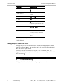
Parameter
Connect*
Admin Status**
Range of Values
YES
NO
UP
DOWN
Rate
1 Ts to 10 Ts
ML Slot*
IO-1 up to the maximum
supported by the chassis
ML Channel*
EX1 up to the maximum
supported by the selected main
link module
Destination Slot**
CL, IO-1 to IO-10
Destination Port**
1 to 8 for external ports
1 to 63 (1 to 84) for internal
(virtual) PDH ports
NONE
* MP-2100/2104 only
** MP-4100 only
Configuring the Main Link Port
Configure the port of the main link module to which the HSF payload is routed
using the command DEF CH SS CC, where SS is the main link slot number and
CC is the main link port number.
To comply with the requirements of the IEEE PC37.94 standard draft, the
Megaplex main link port carrying the HSF payload must be configured with DATA
OOS sequence=FF.
3.
Timeslot Routing
Configure the HSF module timeslot routing, using the command DEF TS.
2
Timeslot Routing
HSF-1, HSF-2
MP-2100/2104 Ver. 12, MP-4100 Ver. 1.6
Contents
Chapter 1. Introduction
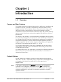
1.1
1.2
1.3
1.4
Overview.................................................................................................................... 1-1
Purpose and Main Features ..................................................................................... 1-1
Product Options...................................................................................................... 1-1
Application Considerations ...................................................................................... 1-2
Physical Description ................................................................................................... 1-2
Functional Description................................................................................................ 1-3
Background Information.......................................................................................... 1-3
Functional Block Diagram ........................................................................................ 1-4
Link Interface Characteristics .................................................................................. 1-5
Timing .................................................................................................................... 1-5
Alarm Indications .................................................................................................... 1-5
Diagnostics ............................................................................................................. 1-6
Technical Specifications.............................................................................................. 1-6
Chapter 2. Installation and Operation
2.1
2.2
2.3
2.4
Introduction ............................................................................................................... 2-1
Installing the Module in the Chassis ............................................................................ 2-2
Connecting the Cables................................................................................................ 2-2
Normal Indications ..................................................................................................... 2-3
Module Status Indication......................................................................................... 2-3
Link Status Indications ............................................................................................ 2-3
Chapter 3. Configuration
3.1
3.2
3.3
3.4
3.5
Configuration Sequence for the MP-2100/2104 Chassis.............................................. 3-1
Configuration Sequence for the MP-4100 Chassis ....................................................... 3-2
Configuration Parameters........................................................................................... 3-2
Assigning Timeslots .................................................................................................... 3-3
Displaying Status and Configuration Information ........................................................ 3-4
Chapter 4. Troubleshooting and Diagnostics
4.1
4.2
Troubleshooting Instructions ...................................................................................... 4-1
Technical Support ...................................................................................................... 4-2
HSF-1, HSF-2
MP-2100/2104 Ver. 12, MP-4100 Ver. 1.6
i
Table of Contents
ii
Installation and Operation Manual
HSF-1, HSF-2
MP-2100/2104 Ver. 12, MP-4100 Ver. 1.6
Chapter 1
Introduction
1.1
Overview
Purpose and Main Features
This manual describes the technical characteristics, applications, installation and
operation of the HSF-1 and HSF-2 teleprotection interface modules for the
Megaplex modular E1/T1 multiplexer systems. The modules have single or dual
fiber optic interface, which provides a secure link in hazardous or hostile
environments, increases the maximum connection range, and provides immunity
against electrical interference and protection against the deleterious effects of
ground loops.
The function of the modules is to interface between the Megaplex and an external
fiber optic link complying with the requirements of the IEEE PC37.94 standard draft
for n×64 kbps fiber optic interfaces to teleprotection equipment. This enables the
teleprotection equipment to use the advanced transport capabilities offered by
Megaplex equipment. The HSF modules support a teleprotection traffic payload in
the range of 64 to 640 kbps per port (that is, n = 1 to 10).
The fiber optic link operates at a line rate of 2.048 Mbps and uses the framing
mode specified in the IEEE PC37.94 standard draft (this framing is based on the
G.732N framing for E1 links).
The modules have one or two optical ports, operating at a nominal wavelength of
850 mm. The ports are terminated in two ST connectors, for connection to
standard multimode fibers.
Product Options
The HSF modules are available in a single- or dual interface versions and are
called HSF-1 and HSF-2, respectively. HSF-1 is supported by the Megaplex-2100
and Megaplex-2104 chassis only, while HSF-2 is also supported by
Megaplex-4100.
Note
HSF-1, HSF-2
In this manual, the generic term Megaplex is used when the information is
applicable to all the Megaplex chassis and the term HSF is used when the
information is applicable to both the HSF-1 and HSF-2 versions. The complete
equipment designation is used only for information applicable to a specific
equipment version.
MP-2100/2104 Ver. 12, MP-4100 Ver. 1.6
Overview
1-1
Chapter 1 Introduction
Installation and Operation Manual
Application Considerations
The HSF modules can be installed in any I/O slot. The number of HSF modules
actually installed in a Megaplex can be selected in accordance with the number of
fiber optic links required by the specific user’s application.
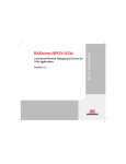
In accordance with the IEEE PC37.94 standard draft, each 64 kbps teleprotection
traffic payload carried by the HSF module occupies two timeslots on the HSF
optical link, and is processed by the HSF module for transport in a single 64 kbps
main link timeslot.
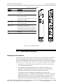
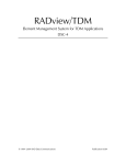
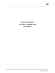
A typical HSF-1 application is shown in Figure 1-1.
Figure 1-1. Typical HSF-1 Application
The following configuration restrictions apply:
•
HSF payload timeslots must always be defined as data timeslots.
•
To comply with the requirements of the IEEE PC37.94 standard draft, the
Megaplex main link port carrying the HSF payload must be configured with
DATA OOS sequence=FF.
•
The equipment connected to the remote end of the link should use loopback
timing (i.e., its timing must be locked to the Megaplex nodal timing).
1.2
Physical Description
HSF-1 and HSF-2 are 4U-high modules, which occupy one module slot in the
Megaplex chassis. All their functions are configured by software.
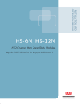
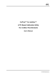
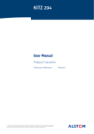
The panels of the HSF-1 and HSF-2 modules are shown in Figure 1-2. Table 1-1
explains the functions of the indicators located on the module panel.
Each port has two optical connectors, designated TX (transmit output) and RX
(receive input).
1-2
Physical Description
HSF-1, HSF-2
MP-2100/2104 Ver. 12, MP-4100 Ver. 1.6
Installation and Operation Manual
Chapter 1 Introduction
Table 1-1. HSF Indicators
Indicator
Description
ALARM
Lights when a fault has been detected in
the module
HSF-1
ALARM
TST
ON LINE
Lights when the module is operating
properly and is active.
Off when the module is defective, or is not
connected to a TDM bus
LOC S. LOSS
Lights when the local module has lost
frame synchronization
REM S. LOSS
Lights when a loss-of-frame
synchronization indication is received by
the module from the equipment connected
to the remote end of the fiber-optic link
HSF-2
LOC
ALARM
ON
LINE
TST
REM
LOC
S. LOSS
ON
LINE
REM
S. LOSS
L
I
N
K
RX 1
RX
TX
TX
L
I
N
K
1
ALARM
TST
ON
TST
LOC
REM
S. LOSS
Not used
RX
L
I
N
K
2
TX
HSF-1
HSF-2
Figure 1-2. HSF Module Panels
1.3
Functional Description
Background Information
The frame structure used by the HSF external port is in accordance with the IEEE
PC37.94 standard draft. The frame structure specified in this standard draft is
similar to the 2.048 Mbps frame structure of ITU-T Rec. G.704 and the no-signaling
frame structure (G.732N) of ITU-T Rec. G.732. The main differences are as follows:
•
Timeslots 0 to 7 are used for the teleprotection link overhead, and therefore
the first payload timeslot is 8.
•
The payload data encoding method uses two teleprotection link bits to
represent each teleprotection payload bit. Therefore, two link timeslots
(128 kbps) are needed for each 64 kbps teleprotection channel.
For example, when the teleprotection payload rate is 64 kbps, the
teleprotection link rate is 128 kbps and used timeslots are 8 and 9. The other
payload timeslots, that is, 10 to 31, carry alternating “1” and “0”. However,
within the HSF module the data received from the telecommunication
equipment is decoded and the contents of each pair of timeslots is restored
HSF-1, HSF-2
MP-2100/2104 Ver. 12, MP-4100 Ver. 1.6
Functional Description
1-3
Chapter 1 Introduction
Installation and Operation Manual
to 64 kbps before being routed to a Megaplex TDM bus. Therefore, in this
example, only one timeslot is transferred to the TDM bus.
The reverse process occurs in the HSF transmit path: each timeslot received
from a TDM bus is encoded and inserted in two consecutive timeslots
(starting with 8).
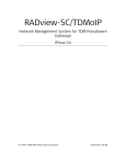
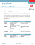
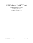
Functional Block Diagram
Figure 1-3 shows the functional block diagram of the HSF-2 module. The HSF-1
block diagram is similar, the only difference being in that only one link is
available.
The HSF module includes the following main subsystems:
•
TDM bus interfaces: four independent TDM bus interfaces, one for each
Megaplex TDM bus.
•
Routing matrix: controls the routing of the payload timeslots between the
TDM bus interfaces and the HSF interface.
HSF-2
TDM
Bus A
Interface
TDM
Bus B
Interface
TDM Bus D
TDM Bus C
TDM Bus B
Link 1
Link
Interface
(Port EX2)
Link 2
Routing
Matrix
TDM
Bus C
Interface
TDM Bus A
Link
Interface
(Port EX1)
TDM
Bus D
Interface
Internal
Clock & Timing
Signals
Figure 1-3. HSF-2 Functional Block Diagram
1-4
Functional Description
HSF-1, HSF-2
MP-2100/2104 Ver. 12, MP-4100 Ver. 1.6
Installation and Operation Manual
•
Chapter 1 Introduction
Link interface:
The transmit path of the interface performs the following main functions:
Fills constant data in accordance with the IEEE PC37.94 standard draft
in the timeslots that do not carry payload.
Generates frames in accordance with the IEEE PC37.94 standard draft
and inserts the processed data stream in the appropriate timeslots of
the transmit frame.
Prepares the resulting data stream, having a line rate of 2.048 Mbps,
for transmission through the HSF fiber-optic link interface.
The receive path performs the following main functions:
Recovers the receive signal from the optical signal received from the
teleprotection equipment.
Synchronizes to the incoming signal frame, and retrieves the payload
timeslots and decodes the received payload.
Transfers the retrieved payload timeslots to the TDM bus (through
the routing matrix).
•
Timing subsystem: generates the internal clock and timing signals required by
the HSF link transmit path. These signals are locked to the Megaplex nodal
timing.
Link Interface Characteristics
The HSF modules have single or dual optical interface for operation over
multimode fibers terminated in a ST connector. The nominal wavelength is
850 mm.
The fiber optic interface offers high performance and has a wide dynamic range,
which ensures that the receiver will not saturate even when using short fiber
optic cables (saturation is caused when the optical power applied to the receiver
exceeds its maximum allowed input power, and results in very high bit error
rates).
Timing
The HSF transmit path timing is derived from the nodal clock used by the
Megaplex.
The nodal clock source can be selected in accordance with system requirements,
as explained in the corresponding Megaplex Installation and Operation Manual.
The HSF module cannot be selected as timing source.
The receive path of the HSF optical port uses the clock signal recovered from the
corresponding received line signal. Therefore, the user’s teleprotection
equipment should use loopback timing, that is, its link transmit clock should be
locked to the receive clock derived from the receive data of the same port.
HSF-1, HSF-2
MP-2100/2104 Ver. 12, MP-4100 Ver. 1.6
Functional Description
1-5
Chapter 1 Introduction
Installation and Operation Manual
Alarm Indications
The HSF module provides the following alarm indications:
•
To the local teleprotection equipment: in case of local loss of frame
synchronization on the corresponding main link port, the HSF module inserts
a 1010... sequence in the timeslots sent to the teleprotection equipment.
•
To the remote equipment: in case a local loss of frame synchronization or
loss of input signal occurs on the receive path of the HSF module, the module
sends a stream of “1” to the TDM bus toward the corresponding main link
port (equivalent to an FF out-of-service (OOS) sequence).
Diagnostics
The HSF module panel includes indicators that display the status of the link
interface (loss of local and remote synchronization), and the presence of alarms
in the module.
1.4
Technical Specifications
Number of Links 1 or 2
Payload Rate
n × 64 kbps per port, where n = 1 to 10 (64 to 640 kbps)
Megaplex
Support
HSF-1
MP-2100, MP-2104
HSF-2
MP-2100, MP-2104, MP-4100
Nominal Bit Rate
2.048 Mbps
Wavelength
850 nm
Fiber Type
62.5/125 μm multimode
Transmitter Type
VSCEL
Power Coupled into Fiber
-19 to –11 dBm (-15 dBm typical)
Receiver Sensitivity
-32 dBm
Optical Budget
13 dB
Maximum Receiver Input Power
-11 dBm
Receiver Dynamic Range
21 dB
Typical Range
2 km (with 6.8 dB margin)
Frame
IEEE PC37.94 draft
Connectors
ST
Line Interface
Characteristics
1-6
Technical Specifications
HSF-1, HSF-2
MP-2100/2104 Ver. 12, MP-4100 Ver. 1.6
Installation and Operation Manual
Chapter 1 Introduction
Timing
Internal Oscillator
±30 ppm
Indicators
Module
Alarm
Link Interface
• On-line
• Local sync loss
• Remote sync loss
Configuration
HSF-1, HSF-2
MP-2100/2104 Ver. 12, MP-4100 Ver. 1.6
Programmable via Megaplex management
system
Technical Specifications
1-7
Chapter 1 Introduction
1-8
Technical Specifications
Installation and Operation Manual
HSF-1, HSF-2
MP-2100/2104 Ver. 12, MP-4100 Ver. 1.6
Chapter 2
Installation and Operation
2.1
Introduction
This chapter provides installation, configuration and operation instructions for
the HSF-1 and HSF-2 modules.
The information presented in this chapter supplements the Megaplex installation,
configuration and operation instructions contained in the corresponding
Megaplex Installation and Operation Manual.
Warning
Before performing any internal settings, adjustment, maintenance, or repairs,
first disconnect all the cables from the module, and then remove the module
from the Megaplex enclosure.
No internal settings, adjustment, maintenance, and repairs may be performed by
either the operator or the user; such activities may be performed only by a skilled
technician who is aware of the hazards involved.
Always observe standard safety precautions during installation, operation, and
maintenance of this product.
Caution The HSF modules contain components sensitive to electrostatic discharge (ESD).
To prevent ESD damage, always hold the module by its sides, and do not touch
the module components or connectors.
HSF modules comply with laser product performance standards set by government
agencies for Class 1 laser products. The modules do not emit hazardous light, and
the beam is totally enclosed during all operating modes of customer operation and
maintenance.
HSF modules are shipped with protective covers installed on all the optical
connectors. Keep the covers for reuse, to reinstall the cover over the optical
connector as soon as the optical cable is disconnected.
HSF-1, HSF-2
MP-2100/2104 Ver. 12, MP-4100 Ver. 1.6
Introduction
2-1
Chapter 2 Installation and Operation
Installation and Operation Manual
For your safety:
Warning
• Before turning on the equipment, make sure that the fiber optic cable is intact
and is connected to the optical transmitter.
• Do not use broken or unterminated fiber-optic cables/connectors.
• Do not look straight at the laser beam, and do not look directly into the
optical connectors while the module is operating.
• Do not attempt to adjust the laser drive current.
• The use of optical instruments with this product will increase eye hazard.
• Use of controls or adjustment or performing procedures other than those
specified herein may result in hazardous radiation exposure.
ATTENTION: The laser beam may be invisible!
2.2
Installing the Module in the Chassis
The HSF modules can be installed in an operating chassis (hot insertion). Avoid
looking directly into the optical connectors.
For general installation procedures and safety instructions, refer to the
corresponding Megaplex Installation and Operation Manual.
Insert the HSF module in the prescribed I/O slot and fasten it with its two screws.
2.3
Connecting the Cables
Before starting, refer to the installation plan to determine the fiber-optic cables
intended for connection to the HSF module.
Connect the prescribed cables to the following connectors on the module panel:
•
Connect the transmit cable to the TX connector
•
Connect the receive cable to the RX connector.
Before connecting, clean the optical connectors using an approved solvent, and
dry thoroughly using optical tissue. Avoid sharp bends and twisting of the fiber
optic cables.
2-2
Connecting the Cables
HSF-1, HSF-2
MP-2100/2104 Ver. 12, MP-4100 Ver. 1.6
Installation and Operation Manual
2.4
Chapter 2 Installation and Operation
Normal Indications
Module Status Indication
When the link connected to the HSF module is operational, its ALARM indicator
must be off.
Link Status Indications
The normal indications for an operational link interface are as follows:
HSF-1, HSF-2
•
The ON-LINE indicator of an active link must light steadily.
•
If the other communication equipment on the link is not yet operative, the
corresponding LOC S. LOSS and/or REM S. LOSS indicator may light. These
indicators must turn off as soon as the link with the remote equipment is
established.
MP-2100/2104 Ver. 12, MP-4100 Ver. 1.6
Normal Indications
2-3
Chapter 2 Installation and Operation
2-4
Normal Indications
Installation and Operation Manual
HSF-1, HSF-2
MP-2100/2104 Ver. 12, MP-4100 Ver. 1.6
Chapter 3
Configuration
This chapter provides configuration information for HSF modules installed in the
Megaplex-2100/2104 or Megaplex-4100 chassis. For general instructions and
additional configuration procedures, refer to Megaplex-2100/2104 Installation
and Operation Manual and Megaplex-4100 Installation and Operation Manual,
respectively.
The configuration is performed by means of the management system used to
control the Megaplex unit:
•
Supervision terminal or Telnet – refer to the Megaplex-2100/2104 or
Megaplex-4100 Installation and Operation Manual for instructions.
•
Web browser – refer to the Megaplex-4100 Installation and Operation Manual
for instructions.
•
Network management system, e.g., the RADview network management
system – refer to the RADview User's Manual for instructions.
3.1
Configuration Sequence for the MP-2100/2104
Chassis
To configure an HSF-1, HSF-2 module and put it into service:
1. Add an HSF-1, HSF-2 module not yet installed in the Megaplex-2100/2104
chassis to the database. This allows preconfiguring the module parameters,
so that the module will immediately start operating in the desired mode as
soon as it is installed in the enclosure. For the supervision terminal, use the
DEF SYS command.
2. Configure the HSF-1, HSF-2 channel parameters:
To define the parameters of all the module channels on the supervision
terminal, type the command:
DEF CH SS *
To define the parameters of a desired channel on the supervision
terminal, type the command:
DEF CH SS CC
where SS is the slot number, and CC is the channel number (1 or 2). For the
parameter description, see Table 3-1.
3. Assign timeslots as described in Section 3.4.
HSF-1, HSF-2
MP-2100/2104 Ver. 12, MP-4100 Ver. 1.6
3-1
Chapter 3 Configuration
Note
Installation and Operation Manual
Make sure to plan ahead the configuration sequence, because
Megaplex-2100/2104 databases can be updated only after correctly completing
the configuration activities: any sanity error will prevent saving the changes to
the database being modified.
3.2
Configuration Sequence for the MP-4100
Chassis
To configure an HSF-2 module and put it into service:
1. Add an HSF-2 module not yet installed in the Megaplex-4100 chassis to the
database. This allows preconfiguring the module parameters, so that the
module will immediately start operating in the desired mode as soon as it is
installed in the enclosure.
For the supervision terminal, use the Configuration>System>Card Type
screen.
2. Configure the CL or M8E1/M8T1/M8SL module port parameters (depending on
the HSF-2 module application). For the configuration procedure, refer to the
appropriate Installation and Operation Manual.
3. Configure the HSF-2 port parameters. For the supervision terminal, use the
Configuration>Physical Ports>I/O screen.
4. Configure the timeslot assignment of each module port, using the
Configuration>System>TS Assignment screen.
Note
Make sure to plan ahead the configuration sequence, because Megaplex-4100
databases can be updated only after correctly completing the configuration
activities: any sanity error will prevent saving the changes to the database being
modified.
3.3
Configuration Parameters
Each HSF-1, HSF-2 port can be independently configured in accordance with the
system requirements.
Table 3-1 explains the programmable parameters of the HSF-1, HSF-2 module
and their ranges of values.
3-2
HSF-1, HSF-2
MP-2100/2104 Ver. 12, MP-4100 Ver. 1.6
Installation and Operation Manual
Chapter 3 Configuration
Table 3-1. Port Parameters
Parameter
Function
Values
Connect
Determines whether the channel is
connected to the internal TDM buses
of the Megaplex chassis
NO
The channel is disconnected. You can still
program the desired parameters, so the
channel will be ready to operate when
needed.
YES
The channel is connected to a legacy main
link port, and can carry traffic.
(MP-2100/2104
only)
Default: NO
Admin Status
Used to enable/disable the flow of
traffic through the selected port
(MP-4100 only)
UP
The flow of traffic is enabled.
DOWN
The flow of traffic is disabled. This state
should be selected as long as the port
configuration has not yet been completed,
or when it is necessary to stop traffic flow
through the port.
Default: DOWN
Rate
Specifies the port rate in timeslots
1 Ts to 10 Ts
Default: 1 Ts
ML Slot
Selects the I/O slot number of the
destination main link module
(MP-2100/2104
only)
Default: IO-1
Default: EX1
Selects the number of the main link
port on the selected destination main
link module
ML Channel
(MP-2100/2104
only)
Destination Slot
(MP-4100 only)
Specifies the module (I/O slot) to
The available selections are the CL module installed
which the data stream handled by the in the chassis, and I/O modules IO-1 to IO-10.
port is routed.
Destination Port Specifies the port to which the data
The available selections are 1 to 8 for external ports,
(MP-4100 only) stream handled by the port is routed. or 1 to 63 (1 to 84) for internal (virtual) ports
(actual range depends on the destination module).
3.4
Assigning Timeslots
After performing the configuration of the individual module channels, it is
necessary to assign the uplink bandwidth to each connected port.
HSF-1, HSF-2
•
For the module installed in the MP-2100/2104 chassis, use the DEF TS
command to assign timeslots as explained in the Megaplex-2100/2104
Installation and Operation Manual.
•
For the module installed in the MP-4100 chassis, use the
Configuration>System>TS Assignment screen.
MP-2100/2104 Ver. 12, MP-4100 Ver. 1.6
Assigning Timeslots
3-3
Chapter 3 Configuration
Note
Installation and Operation Manual
As a result of the IEEE PC37.94 requirements, the following configuration
guidelines apply:
•
HSF payload timeslots must always be defined as data timeslots.
•
To comply with the requirements of the IEEE PC37.94 standard draft, the
Megaplex main link port carrying the HSF payload must be configured with
DATA OOS sequence=FF.
3.5
Displaying Status and Configuration
Information
The Megaplex-2100/2104 user can read the HSF-1, HSF-2 status and
configuration information using the DSP ST CH command. For a general
description of this command, refer to Appendix F of the Megaplex-2100/2104
Installation and Operation Manual.
The DSP ST CH command includes two sections:
•
Hardware Config/Status: displays the displays the optical interface type
(nominal wavelength – 850 nm, Laser (VCSEL) transmitter, ST connector).
•
Software Configuration: displays a data form similar to that displayed by the
DEF CH command, showing the current configuration of each channel. For a
description of the displayed parameters, refer to Table 3-1.
The Megaplex-4100 user can read the configuration on every port of the I/O
modules using the Configuration>Physical Ports>I/O menu. For a general
description of these menus, refer to Chapter 4 of the Megaplex-4100 Installation
and Operation Manual.
3-4
HSF-1, HSF-2
MP-2100/2104 Ver. 12, MP-4100 Ver. 1.6
Chapter 4
Troubleshooting and
Diagnostics
The HSF modules do not support loopbacks and tests.
Caution
The activation of a loopback or test on the HSF link will disconnect the external
link, therefore this is not allowed under any circumstances.
For a description of the alarm and configuration (“sanity”) error messages
generated by HSF module, refer to Appendix B of the Megaplex-2100/2104
Installation and Operation Manual or Chapter 5 of the Megaplex-4100 Installation
and Operation Manual.
4.1
Troubleshooting Instructions
In case a problem occurs, check the displayed alarm messages and refer to the
corresponding Megaplex Installation and Operation Manual for their
interpretation.
If the problem is related to the HSF module, pull the module out wait about one
minute. After reinserting the module, read the power-up test results and replace
the module if any fault is reported.
If after collecting all the relevant information, the problem appears to be related
to the operation of the main link serving the HSF module, perform the actions
listed below, until the problem is corrected:
•
If the fault occurs after configuration changes or on the first time the module
is operated, check for correct configuration in accordance with Chapter 3.
•
If traffic to other modules is served by the same main link port as used by the
HSF module, troubleshoot the main link module:
Activate the local loopback on the corresponding main link port. If the
S. LOSS LOC indicator of the local main link port turns OFF while the loop
is connected, the problem is external. Check cable connections, and the
transmission equipment providing the link to the remote Megaplex unit.
You can rapidly check the link to the remote Megaplex unit by activating
the remote main link loopback at the remote unit. If the corresponding
link operates OK, the S. LOSS LOC indicator of the corresponding local
main link turns OFF.
If the problem persists, the main link module is probably defective and must be
replaced.
HSF-1, HSF-2
MP-2100/2104 Ver. 12, MP-4100 Ver. 1.6
Troubleshooting Instructions
4-1
Chapter 4 Troubleshooting and Diagnostics
4.2
Installation and Operation Manual
Technical Support
Technical support for this product can be obtained from the local distributor from
whom it was purchased.
For further information, please contact the RAD distributor nearest you or one of
RAD's offices worldwide. This information can be found at www.rad.com (offices
– About RAD > Worldwide Offices; distributors – Where to Buy > End Users).
4-2
Technical Support
HSF-1, HSF-2
MP-2100/2104 Ver. 12, MP-4100 Ver. 1.6
24 Raoul Wallenberg Street, Tel Aviv 69719, Israel
Tel: +972-3-6458181, Fax +972-3-6483331, +972-3-6498250
E-mail: [email protected], Web site: http://www.rad.com
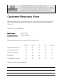
Customer Response Form
RAD Data Communications would like your help in improving its product documentation.
Please complete and return this form by mail or by fax or send us an e-mail with your
comments.
Thank you for your assistance!
Manual Name:
HSF-1, HSF-2
Publication Number:
764-245-02/08
Please grade the manual according to the following factors:
Excellent
Good
Fair
Poor
Very Poor
Installation instructions
Operating instructions
Manual organization
Illustrations
The manual as a whole
What did you like about the manual?
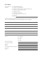
Error Report
Type of error(s) or
problem(s):
Incompatibility with product
Difficulty in understanding text
Regulatory information (Safety, Compliance, Warnings, etc.)
Difficulty in finding needed information
Missing information
Illogical flow of information
Style (spelling, grammar, references, etc.)
Appearance
Other
Please list the exact page numbers with the error(s), detail the errors you found (information missing,
unclear or inadequately explained, etc.) and attach the page to your fax, if necessary.
Please add any comments or suggestions you may have.
You are:
Who is your distributor?
Your name and company:
Job title:
Address:
Direct telephone number and extension:
Fax number:
E-mail:
Distributor
End user
VAR
Other
Publication No. 764-245-02/08
International Headquarters
24 Raoul Wallenberg Street
Tel Aviv 69719, Israel
Tel. 972-3-6458181
Fax 972-3-6498250, 6474436
E-mail [email protected]
North America Headquarters
900 Corporate Drive
Mahwah, NJ 07430, USA
Tel. 201-5291100
Toll free 1-800-4447234
Fax 201-5295777
E-mail [email protected]
www.rad.com
The Access Company