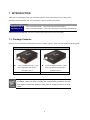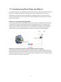
1
POC252 Series User's Manual P/N 1073047 • REV A • ISS 27AUG15 Copyright © 2015 United Technologies Corporation Interlogix is part of UTC Building & Industrial Systems, Inc. a unit of United Technologies Corporation. All rights reserved. Trademarks and patents The POC252 name and logo are trademarks of United Technologies. Other trade names used in this document may be trademarks or registered trademarks of the manufacturers or vendors of the respective products. Manufacturer Interlogix 3211 Progress Drive, Lincolnton, NC 28092 USA Authorized EU manufacturing representative: UTC Climate Controls & Security B.V., Kelvinstraat 7, 6003 DH Weert, Netherlands Intended use Use this product only for the purpose it was designed for; refer to the data sheet and user documentation for details. For the latest product information, contact your local supplier or visit us online at www.interlogix.com. Certification N4131 FCC compliance This equipment has been tested and found to comply with the limits for a Class A digital device, pursuant to part 15 of the FCC Rules. These limits are designed to provide reasonable protection against harmful interference when the equipment is operated in a commercial environment. This equipment generates, uses, and can radiate radio frequency energy and, if not installed and used in accordance with the instruction manual, may cause harmful interference to radio communications. You are cautioned that any changes or modifications not expressly approved by the party responsible for compliance could void the user's authority to operate the equipment. ACMA compliance Notice! This is a Class A product. In a domestic environment this product may cause radio interference in which case the user may be required to take adequate measures. Canada This Class A digital apparatus complies with Canadian ICES-003. Cet appareil numérique de la classe A est conforme á la norme NMB-003du Canada. European Union 2004/108/EC (EMC Directive): Hereby, UTC Building & Industrial Systems, Inc. directives declares that this device is in compliance with the essential requirements and other relevant provisions of Directive 2004/108/EC. Contact Information For contact information, see www.interlogix.com or www.utcfssecurityproducts.eu. 2 TABLE OF CONTENTS 1. 2. INTRODUCTION .................................................................................................................................................. 4 1.1. PACKAGE CONTENTS......................................................................................................................................... 4 1.2. INTRODUCING LONG REACH POWER OVER ETHERNET ..................................................................................... 5 1.3. PRODUCT FEATURES ......................................................................................................................................... 6 1.4. PRODUCT SPECIFICATIONS ................................................................................................................................ 7 1.4.1. POC252-1CXP-1T Specifications ............................................................................................................ 7 1.4.2. POC252-1CX-1P Specifications .............................................................................................................. 9 HARDWARE DESCRIPTION ........................................................................................................................... 11 2.1. 2.1.1. POC252-1CXP Physical Dimensions..................................................................................................... 11 2.1.2. POC252-1CXP-1T Front Panel / Rear Panel ........................................................................................ 11 2.1.3. POC252-1CXP LED Indicators ............................................................................................................. 12 2.2. 3. 4. POC252-1CXP ............................................................................................................................................... 11 POC252-1CX ................................................................................................................................................. 13 2.2.1. POC252-1CX-1P Physical Dimensions ................................................................................................. 13 2.2.2. POC252-1CX Front Panel / Rear Panel ................................................................................................ 14 2.2.3. POC252-1CX LED Indicators ................................................................................................................ 14 INSTALLATION ................................................................................................................................................. 15 3.1. INSTALLATION PRECAUTIONS ......................................................................................................................... 15 3.2. POWER OPTIONS: ............................................................................................................................................. 16 3.3. APPLICATIONS OF POC252-KIT WITH COAXIAL CABLE .................................................................................. 17 3.4. OPTIONAL - DIN-RAIL MOUNTING ................................................................................................................. 20 TROUBLESHOOTING ....................................................................................................................................... 21 APPENDIX A: NETWORKING CONNECTION .................................................................................................... 22 A.1 SWITCH’S RJ45 PIN ASSIGNMENTS ...................................................................................................................... 22 A.2 RJ45 CABLE PIN ASSIGNMENTS ........................................................................................................................... 22 3 1. INTRODUCTION Thank you for purchasing IFS PoE over Coaxial the POC252-1CXP and POC252-1CX, consisting of the POC252-1CXP and POC252-1CX. The descriptions of the two models are as follows: POC252 Power over Coax POC252-1CXP-1T 1-Port 10/100TX PoE PD + 1-Port Coax Long Reach PoE Injector POC252-1CX-1P 1-Port 10/100TX PoE PSE + 1-Port Coax Long Reach PoE Extender (Camera End) “POC252-1CXP/POC252-1CX” mentioned in this Manual represents the above two models. 1.1. Package Contents Open the box of the POC252-1CXP/POC252-1CX and carefully unpack it. The box should contain the following items: For POC252-1CXP-1T/POC252-1CX-1P 1-Port 10/100TX PoE PD + 1-Port 1-Port 10/100TX PoE PSE + 1-Port Coax Long Reach PoE Injector – Coax Long Reach PoE Extender – POC252-1CXP x1 POC252-1CX x1 User's Manual x 1 Warning Sticker x 1 If any of these are missing or damaged, please contact your dealer immediately; if possible, retain the carton including the original packing material, and use them again to repack the product in case there is a need to return it to us for repair. 4 1.2. Introducing Long Reach Power over Ethernet IFS POC252 series PoE over Coaxial Extender is designed to extend IP Ethernet transmission and inject power over an existing coaxial cable or for distance up to 1000m (3280ft) to PoE IP camera, PoE Wireless AP and any 802.3at device that complies with powered device (PD). It is perfect solution for sending IP Video links and power to remote PoE IP camera installation that are beyond the 100 meters distance limit of Ethernet. Power over Coaxial Cable Application The Long Reach PoE solution allows Ethernet Data and PoE or PoE+ to transmitted using coaxial, UTP or twisted-pair cable. Based on IEEE 802.3at Power over Ethernet Plus and up to 25 watts of power output, IFS PoE extender solution eliminates the need for additional remote site power while allowing a single PoE source, such as a PoE network switch, to provide power to both POC Extenders and the camera at long range. This feature eliminates the need for local and remote site power supplies. Stable Operating Performance under Difficult Environments The POC252-1CXP and POC252-1CX extender is the perfect solution for extended distance data and power transmission for warehouses, parking lots, campuses, casinos, and many more. They can operate stably under temperature range from -10 to 60 degrees C which enables the users to conveniently apply the device in almost any location of the network. 5 1.3. Product Features Physical Port 1 coaxial interface for output power and 1 10/100BASE-TX port supports IEEE 802.3at PoE PD (POC252-1CXP) 1 power jack supports 56V DC Power input (POC252-1CXP) 1 coaxial interface for input and 110/100BASE-TX port supports IEEE 802.3at PoE PSE (POC252-1CX) Power over Ethernet Eliminates Power cabling with PoE over Coaxial Supports Power over Ethernet PSE, PoE Injector Power and Ethernet data transmission over coaxial up to 1km Complies with IEEE 802.3at Power over Ethernet PD on RJ45 port Supports Long Reach PoE power up to 30.8 watts (Vary on Power Source and Coaxial Distance) Supports PoE Power up to 25 watts (Vary on Power Source and Coaxial Distance) Auto detect remote powered device (PD) Plug and Play, no PC required Industrial Case / Installation Supports extensive LED indicators for network diagnostics Metal case protection Compact size, DIN-rail and wall mount designed Power Input: External 56VDC input or 802.3at PoE power input from RJ45 port (POC252-1CXP) Power Input: PoC (Power over Coaxial) power input (POC252-1CX) Supports EFT protection 2000 VDC for power line Supports 2000 VDC Ethernet ESD protection -10 to 60 degrees C operating temperature 6 1.4. Product Specifications 1.4.1. POC252-1CXP-1T Specifications Model POC252-1CXP-1T / Long Reach PoE Injector Hardware Specifications Copper Power over Ethernet Ethernet Interface Data Rate Cabling Maximum Distance Maximum Frame sizes Connectivity Power Output Cabling Maximum distance 1 x 10/100BASE-TX RJ45 Auto-negotiation/ Auto-MDI/MDI-X IEEE 802.3at PoE PD (Powered Device) Input Range: 56V DC Supports both Mid-Span and End-Span PSE 100/100Mbps Cat5e or above 100m 1522bytes 1 x BNC female connector Long Reach PoE over coaxial PSE (Power Source Equipment) BNC center pole : DC+ / Hi BNC shield : DC - / Lo 41~56V DC (Depend on what is the DC/PoE Power Input and the length of coaxial cable) Coaxial cable: 75 ohm RG-6/U cable, less than 12Ω/1000 ft RG-59/U cable, less than 30Ω/1000 ft. Max. 1000M with PoE output (3,280ft.) Max. 1200M without PoE output (3,937ft.) Long Reach Ethernet Standard IEEE 1901 Long Reach PoE Interface Modulation Type Wavelet-OFDM Security 128-bit AES encryption Frequency Band 2 ~ 28 MHz RG6 Cable Distance Performance Data Rate (Upload / Download) POC252-1CX 802.3at PoE Output Capability POC252-1CXP W/56V DC IN POC252-1CX P W/30W PoE+ IN 200m 93 / 93 Mbps 29.9W 16.9W 400m 92 / 93 Mbps 22.6W 14.3W 600m 88 / 92 Mbps 13.6W 10.2W 800m 75 / 83 Mbps 10.6W 8.3W 1000m 55 / 74 Mbps 8.6W 7.1W Multiple nodes Supports up to 3 POC extenders within 1km (Depend on what is the DC/PoE Power Input and the length of coaxial cable) POC Compatibility POC252-1CXP-1T with POC Extender 7 ESD Protection 4 x LEDs PWR POC LNK PoE In-use LNK/ACT 2KV DC EFT Protection 2KV Enclosure Metal case Installation Wall mount or DIN rail with optional kit Dimensions (W x D x H) 94 x 70 x 26 mm Weight 200g LED Indicators Power Requirements RJ45 PoE Input: 802.3at 56V DC DC Input: 56V DC Standards Conformance Standards Compliance IEEE 802.3 10BASE-T Ethernet IEEE 802.3u 100BASE-TX Fast Ethernet IEEE 802.3af Power over Ethernet (802.3at Type 1) IEEE 802.3at Power over Ethernet (802.3at Type 2) Regulation Compliance FCC Part 15 Class A, CE Environment Temperature Humidity Operating: -10~60 degrees C Storage: -40~75 degrees C Operating: 5~95% (Non-condensing) Storage: 5~95% (Non-condensing) 8 1.4.2. POC252-1CX-1P Specifications POC252-1CX-1P / Long Reach PoE Extender Model Hardware Specifications PoE Standard PoE Output PoE Budget PoE Mode Data Rate 10/100BASE-TX RJ45 Auto-negotiation/ Auto-MDI/MDI-X IEEE 802.3at PoE PSE (Power Source Equipment) 48~56V DC, 600mA max. Up to 25 watts End-span, RJ45 Pin 1/2(+), 3/6(-) 100/100Mbps Cabling Cat5e or above Copper Ethernet Interface Maximum Distance Maximum Frame sizes Long Reach PoE Interface 100M 1522bytes Connectivity 1 x BNC female Long Reach PoE over coaxial PD (Powered Device) BNC center pole : DC+ / Hi BNC shield : DC - / Lo Power Input 48~56V DC Cabling Coaxial cable: 75 ohm RG-6/U cable, less than 12Ω/1000 ft RG-59/U cable, less than 30Ω/1000 ft. Maximum distance Max. 1000M with PoE output (3,280ft.) Max. 1200M without PoE output (3,937ft.) Long Reach Ethernet Standard IEEE 1901 Modulation Type Wavelet-OFDM Security 128-bit AES encryption Frequency Band 2 ~ 28 MHz Encryption AES 128-bit RG6 Cable Distance* Performance POC Compatibility Data Rate** (Upload / Download) POC252-1CX 802.3at/at PoE Output Capability POC252-1C XP w/56V DC IN POC252-1C XP w/30W PoE+ IN POC2502 w/56V DC 200m 93 / 93 Mbps 29.9W 16.9W 22W 400m 93 / 92 Mbps 22.6W 14.3W 18W 600m 92 / 88 Mbps 13.6W 10.2W 15W 800m 83 / 75 Mbps 10.6W 8.3W 10W 1000m 74 / 55 Mbps 8.6W 7.1W 8W With power over coaxial input POC252-1CXP-1T / 1-Port POC Injector POC2502-8CX-2T-2S – 8-Port POC over Coax Switch POC252-16CX-2T-2S –16-Port POC over Coax Switch 9 LED Indicators 4 x LEDs PWR LRP LNK ESD Protection 2KV DC Enclosure Metal case Installation Wall mount or DIN rail with optional kit Dimensions (W x D x H) 94 x 70 x 26 mm Weight 375g Power Requirements BNC Power over Coaxial Input: 48~56V DC PoE In-use LNK/ACT Standards Conformance Standards Compliance Regulation Compliance Environment IEEE 802.3 10BASE-T Ethernet IEEE 802.3u 100BASE-TX Fast Ethernet IEEE 802.3af Power over Ethernet (802.3at Type 1) IEEE 802.3at Power over Ethernet (802.3at Type 2) FCC Part 15 Class A, CE Operating: -10~60 degrees C Storage: -40~75 degrees C Operating: 5~95% (Non-condensing) Storage: 5~95% (Non-condensing) Temperature Humidity * The actual data rate will vary on the quality of the coaxial cable and environment factors. **Downstream means POC252-Injector to POC252-Extender data rate and Upstream is POC252-Extender to POC252-Injector data rate. The actual data rate will vary on the quality of the coax cable as well as environmental factors. It is recommended that only the coax cable with the following properties is used. Coaxial Cable Type RG-59/U Less than 30Ω/1000 ft. RG-6/U Less than 12Ω/1000 ft 10 2. HARDWARE DESCRIPTION 2.1. POC252-1CXP (Injector) 2.1.1. POC252-1CXP Physical Dimensions POC252-1CXP-1T dimensions (W x D x H): 94 x 70.3 x 39.2 mm 2.1.2. POC252-1CXP-1T Front Panel / Rear Panel Figure 2-1 and Figure 2-2 show the front / rear panels of the POC252-1CXP Long Reach PoE over Coaxial Injector. Figure 2-1: POC252-1CXP Front Panel Figure 2-2: POC252-1CXP Rear Panel 11 2.1.3. POC252-1CXP LED Indicators System LED Color PWR Green Function Lit Power ON: PoE+ / PoE power input from RJ45 PoE PD port Power ON: 48~56V DC power input from DC jack Off Power Off LRP Coaxial Interface LED Color LNK Green Function Lit: indicates that the coaxial link is established. Off: indicates that the coaxial link is down. RJ45 10/100BASE-TX Interface LED Color Function PoE IN Amber Lit: indicates the RJ45 port is receiving the PoE Power. LNK/ACT Green Blink: indicates the extender is actively sending or receiving data over that port. 12 2.2. POC252-1CX (Extender) 2.2.1. POC252-1CX-1P Physical Dimensions POC252-1CX-1P dimensions (W x D x H): 94 x 70.3 x 39.2 mm 13 2.2.2. POC252-1CX Front Panel / Rear Panel Figure 2-3 and Figure 2-4 show the front / rear panels of the POC252-1CX Long Reach PoE over Coaxial Extender. Figure 2-3: POC252-1CX Front Panel Figure 2-4: POC252-1CX Rear Panel 2.2.3. POC252-1CX LED Indicators System LED Color Function PWR Green Lit: indicates the power is on. LRP Coaxial Interface LED Color LNK Green Function Lit: indicates that the coaxial link is established. Off: indicates that the coaxial link is down. RJ45 10/100BASE-TX Interface LED Color Function PoE In-Use Amber Lit: indicates the RJ45 Port is providing PoE power LNK/ACT Green Blink: indicates the extender is actively sending or receiving data over that port. 14 3. INSTALLATION This section describes the functionalities of the POC252-1CXP/POC252-1CX components and guides you to how to install it on the desktop. Basic knowledge of networking is expected. Please read this chapter completely before continuing. 3.1. Installation Precautions As the POC252-1CXP is power over coaxial injector, it only can work with IFS power over coaxial extender, the POC252-1CX. Please confirm that other Non-PoE equipment is not connected with the coaxial cable. When you connect the coaxial cable with coax-LAN converter, CCTV camera, etc, it might cause other equipment to damage. DO NOT CONNECT DIRECTLY TO AN ANALOG CAMERA AS IT WILL DAMAGE THE CAMERA BY APPLYING VOLTAGE TO THE ANALOG OUTPUT. The package contains one Warning Sticker, which should be stuck on the coaxial cable connector before using IFS PoE over Coaxial Extender Kit. 15 3.2. Power options: POC252-1CXP Injector There are two ways to power the POC252-Injector Powered via PoE Powered via DC adapter POC252-1CX The POC252-Extender must be powered by the POC252-Injector or POE Switch POC252-1CX must be powered by the POC252-1CXP or POC2502 POC switch over the coaxial cable. Please don’t connect the POC252-Extender to a PoE PSE. 16 3.3. Applications of POC252-KIT with coaxial cable Type 1 – One POC252-1CXP with PoE power input and one POC252-1CX with PoE power output The POC252-Injector is powered via IEEE 802.3at PoE. An IEEE 802.3at compliant PoE PD will automatically be powered by the POC252-Extender via UTP. Functions Power Input POC252 Injector POC252 Extender POC252-1CXP POC252-1CX RJ45 with 802.3at PoE input BNC with DC power over coaxial input Power BNC with DC power over coaxial Output output RJ45 with 802.3at PoE output Installation Instructions Connect the POC252-Injector (POC252-1CXP) and POC252-Extender Step 1 (POC252-1CX) to ends of BNC terminated coaxial cable. Stuck the “Warning Stacker” on the coaxial cable. Connect CAT5/6 UTP cable to POC252-1CXP and IEEE 802.3at compliant PoE Step 2 Switch or PoE Injector. If the PoE switch or PoE injector is powered on already, then the PWR LED of POC252-1CXP and POC252-1CX should lit up immediately. Step 3 Connect CAT5/6 UTP cable to POC252-1CX and IEEE 802.3at complied PoE IP camera or PoE Wireless AP. The POC252-1CXP accepts IEEE 802.3at equipment for optimal power injection. The other Non-standard PoE Power devices may cause the POC252-1CXP to be damaged. 17 Type 2 – One POC252-1CXP with 56V power adapter and one POC252-1CX with PoE power output The POC252-Injector is powered via the external power adapter. The IEEE 802.3at compliant PoE PD will automatically be powered by the POC252-Extender via UTP. LRP Injector POC252-1CXP LRP Extender POC252-1CX Power Input Power adapter with 48~56V DC in BNC with DC power over coaxial input Power Output BNC with DC power over coaxial output RJ45 with 802.3at PoE output Installation Instructions Connect the POC252-Injector (POC252-1CXP) and POC252-Extender Step 1 (POC252-1CX) to ends of BNC terminated coaxial cable. Stick the “Warning Sticker” on the coaxial cable. Step 2 Step 3 Step 4 Connect CAT5/6 UTP cable to POC252-1CXP and non-PoE switch or workstation. Connect 48~56V DC power adapter to POC252-1CXP power socket, then the PWR LED of POC252-1CXP and POC252-1CX should lit up immediately. Connect CAT5/6 UTP cable to POC252-1CX and IEEE 802.3at complied PoE IP camera or PoE Wireless AP. 1. PoE output capacity is based on different DC Power Input / PoE Input. 2. POC252-1CXP has two power input options; only one mode is available at one time. It cannot use PoE power input if power input of DC 52V or 56V is selected. 18 Type 2 – One POC252-1CXP with 56V power adapter and two POC252-1CX with PoE power output for two cameras. 19 3.4. Optional - DIN-Rail Mounting There are two DIN-Rail holes on the left side of the POC252-1CXP/POC252-1CX that allow the device can be easily installed with DIN-Rail mounting. The PLANET optional DIN-Rail mounting Kit – RKE-DIN can be order separately. When need to replace the wall mount application with DIN-Rail application on the POC252-1CXP/POC252-1CX, please refer to following figures to screw the DIN-Rail on the converter. To hang the POC252-1CXP/POC252-1CX, follow the below steps: Step 1: screw the DIN-Rail on the POC252-1CXP/POC252-1CX. Step 2: Lightly press the button of DIN-Rail into the track. Step 3: Check the DIN-Rail is tightly on the track. You must use the screws supplied with the mounting brackets. Damage caused to the parts by using incorrect screws would invalidate your warranty. 20 4. TROUBLESHOOTING This chapter contains information to help you solve issues. If the POC252-1CXP/POC252-1CX is not functioning properly, make sure the POC252-1CXP/POC252-1CX is set up according to instructions in this manual. The maximum distance support by POC252-1CXP/POC252-1CX Solution: 1. The POC252-1CXP/POC252-1CX supports maximum distance of 1km (Data plus Power transmission). What power source can used by POC252-1CXP? Solution: 1. DC 56V power adapter. 2. DC 48V power adapter. 3. IEEE 802.3at High Power over Ethernet Switch. 4. IEEE 802.3af Power over Ethernet Switch. The POC252-1CXP/POC252-1CX Performance is bad Solution: The actual data rate will vary on the quality of the coaxial / UTP cable and environment factors. Make sure the BNC connector is in good condition. If the BNC connector is loose it may affect performance with poor ground. 21 APPENDIX A: NETWORKING CONNECTION A.1 Switch’s RJ45 Pin Assignments 10/100Mbps, 10/100BASE-TX RJ45 Connector pin assignment Contact MDI MDI-X Media Dependant Media Dependant Interface Interface-Cross 1 Tx + (transmit) Rx + (receive) Positive (VCC+) 2 Tx - (transmit) Rx - (receive) Positive (VCC+) 3 Rx + (receive) Tx + (transmit) Negative (VCC-) 4, 5 6 7, 8 Not used Rx - (receive) Not used Tx - (transmit) Not used A.2 RJ45 Cable Pin Assignments The standard RJ45 receptacle/connector 22 PoE Negative (VCC-) Not used There are 8 wires on a standard UTP/STP cable and each wire is color-coded. The following shows the pin allocation and color of straight cable and crossover cable connection: Straight Cable 1 1 2 2 3 3 4 4 5 5 6 6 7 7 8 SIDE 1 8 SIDE 2 Crossover Cable 1 1 2 2 3 3 4 4 5 5 6 6 7 7 8 SIDE 1 8 SIDE 2 SIDE 1 SIDE2 1 = White / Orange 1 = White / Orange 2 = Orange 2 = Orange 3 = White / Green 3 = White / Green 4 = Blue 4 = Blue 5 = White / Blue 5 = White / Blue 6 = Green 6 = Green 7 = White / Brown 7 = White / Brown 8 = Brown 8 = Brown SIDE 1 SIDE2 1 = White / Orange 1 = White / Green 2 = Orange 2 = Green 3 = White / Green 3 = White / Orange 4 = Blue 4 = Blue 5 = White / Blue 5 = White / Blue 6 = Green 6 = Orange 7 = White / Brown 7 = White / Brown 8 = Brown 8 = Brown Figure A-1: Straight-through and Crossover Cable Please make sure your connected cables are with the same pin assignment and color as the above picture before deploying the cables into your network. Information on FAQ: WWW.Interlogix.com Customer Support: WWW.Interlogix.com/support 23