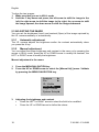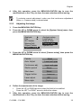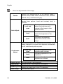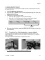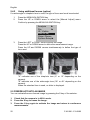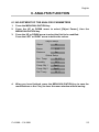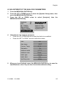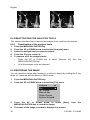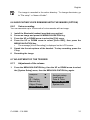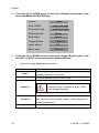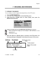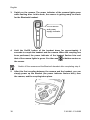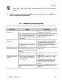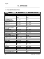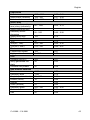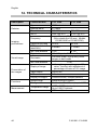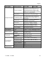
1
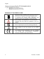
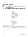
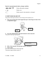
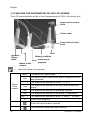
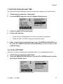
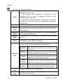
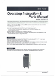
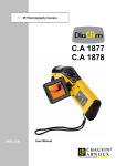
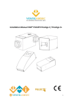
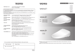
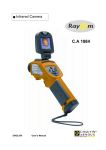
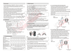
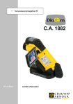
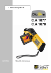
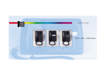
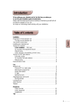
I.R. thermography camera
C.A 1886
C.A 1888
EN G L I S H
User’s manual
English
Thank you for buying a RayCAm I.R. thermography camera.
For best results from your device:
•
read this user manual attentively,
•
observe the precautions for its use
MEANING OF THE SYMBOLS USED
Selective sorting of wastes for the recycling of electrical
and electronic equipment within the European Union.
In conformity with directive DEEE 2002/96/EC: this
equipment must not be treated as household waste.
Risk of danger. See explanations in this user manual
Problems that may affect the operation of the I.R.
camera.
Notes completing the essential operating procedures.
Laser radiation, do not look directly into the LASER
beam.
This marking certifies compliance with the European
"Low Voltage" and "Electromagnetic Compatibility"
directives (2006/95/CE and 2004/108/CE).
2
C.A1886 –C.A1888
English
Characteristics of the laser: Class 2, < 1 mW, wavelength 635nm
WARNING
LASER RADIATION
DO NOT LOOK DIRECTLY INTO THE
BEAM
CLASS 2 LASER DEVICE
C.A1886 – C.A1888
3
English
CONTENTS
1. PRECAUTIONS OF USE ............................................................................................. 6
2. DESCRIPTION ............................................................................................................. 7
2.1 FRONT PANEL ........................................................................................................ 7
2.2 KEYPAD ................................................................................................................... 8
2.3 VIEW OF BACK AND BOTTOM ........................................................................... 8
3. STARTING UP .............................................................................................................. 9
3.1 CHARGING THE BATTERY .................................................................................. 9
3.2 INSTALLING THE BATTERY.............................................................................. 10
3.3 SWITCHING ON AND OFF .................................................................................. 11
3.4 CHECKING THE INFORMATION ON THE LCD SCREEN ............................... 12
3.5 SETTING THE DATE AND TIME ........................................................................ 13
3.6 LOCAL SETTINGS ................................................................................................ 13
4. BASIC FUNCTIONS................................................................................................... 15
4.1 USING THE LCD SCREEN ................................................................................... 15
4.2 SELECTION OF MENUS AND PARAMETERS .................................................. 15
4.3 RESTORING THE DEFAULT SETTINGS ........................................................... 16
5. TAKING SHOTS ......................................................................................................... 16
5.1 ADJUSTING THE CAMERA ................................................................................. 16
5.1.1
Manual focusing ........................................................................................ 16
5.1.2
I.R., Real, and Real + Mix Display. ........................................................... 16
5.2 PARALLAX ADJUSTMENT ................................................................................. 17
5.3 ADJUSTING THE IMAGE ..................................................................................... 18
5.3.1
Automatic adjustment................................................................................. 18
5.3.2
Manual adjustment..................................................................................... 18
5.3.3
Adjusting the image.................................................................................... 19
5.4 MEASUREMENT RANGE .................................................................................... 21
5.4.1
Precautions for « High-temperature » cameras (option) ........................... 21
5.4.2
Using additional lenses (option) ................................................................ 22
5.5 FREEZE/ACTIVATE AN IMAGE ......................................................................... 22
6. ANALYSIS FUNCTION ............................................................................................. 23
6.1 ADJUSTMENT OF THE ANALYSIS PARAMETERS ......................................... 23
6.2 ADJUSTMENT OF THE ANALYSIS PARAMETERS ......................................... 25
6.3 PARAMETERIZING THE ANALYSIS TOOLS ................................................... 27
6.3.1
Analysis by point ........................................................................................ 27
6.3.2
Isothermal analysis .................................................................................... 27
6.3.3
Profile analysis .......................................................................................... 28
6.3.4
Area analysis.............................................................................................. 28
4
C.A1886 –C.A1888
English
6.4 DESACTIVATING THE ANALYSIS TOOLS ...................................................... 30
6.4.1
Deactivation of the analysis tools .............................................................. 30
6.5 RECORDING THE IMAGE ................................................................................... 30
6.6 ASSOCIATING VOICE REMARKS WITH THE IMAGES (OPTION) ............... 31
6.6.1
Voice recording.......................................................................................... 31
6.7 ADJUSTMENT OF THE TRIGGER ...................................................................... 31
6.7.1
Adjustment of the release ........................................................................... 31
7. READING AND ERASING ........................................................................................ 33
7.1 OPENING THE IMAGES ....................................................................................... 33
7.2 PLAYING THE REMARKS (OPTION) ................................................................. 34
7.3 ERASING THE IMAGES ....................................................................................... 35
8. TRANSFERRING IMAGES ...................................................................................... 36
8.1 TRANSFER BY MINI SD CARD .......................................................................... 36
9. CONNECTIONS AND DOWNLOADING ............................................................... 37
9.1 CONNECTION TO A MONITOR .......................................................................... 37
9.2 USING THE BLUETOOTH HEADSET (OPTION) .............................................. 37
10. TROUBLESHOOTING ............................................................................................ 39
11. MAINTENANCE....................................................................................................... 40
11.1 CLEANING AND MAINTAINING THE CAMERA ........................................... 40
Housing of the device................................................................................................. 40
Lens
................................................................................................................... 40
LCD screen ................................................................................................................ 40
11.2 METROLOGICAL CHECK ................................................................................. 40
11.3 REPAIR ................................................................................................................. 40
12. WARRANTY ............................................................................................................. 41
13. APPENDIX ................................................................................................................ 42
13.1 TABLE OF EMISSIVITIES .................................................................................. 42
14. TECHNICAL CHARACTERISTICS...................................................................... 44
15. DELIVERY CONDITION ........................................................................................ 46
C.A1886 – C.A1888
5
English
1. PRECAUTIONS OF USE
Before using the camera, make sure that you have read and understood the
safety precautions described below. Make sure that the camera is used correctly.
Please refer to this manual each time you encounter a hazard symbol. To avoid
exposure to laser radiation, injury, or damage to the device, and be sure that you
use the camera in a risk-free way, observe the safety recommendations given
below:
Do not look directly into the laser beam. Do not point the laser beam at
people.
Do not use the instrument other than for its intended purpose; keep it out
of reach of children and make sure that it is never treated as a toy.
Do not aim the device towards the sun or other source of intense heat.
Use only the recommended batteries and accessories. Do not leave the
device connected to mains when not necessary.
Avoid problems due to condensation.
Moving the I.R. camera rapidly from a cold to a warm place can cause
condensation (droplets of water) to form on its outside and inside surfaces.
You can avoid this problem by placing the camera in the plastic case and letting it
warm slowly to the ambient temperature before withdrawing it from the case.
•
•
•
6
When you switch on the camera, wait 10 to 15 minutes before recording
your first thermograms, to be certain that the camera's temperature has
stabilized and that your measurements are correct.
Focus the objective correctly according to the distance to the target to be
inspected.
Device that may, but only under special conditions, be sensitive to
electrostatic discharges (ESD).
C.A1886 –C.A1888
English
2. DESCRIPTION
2.1 FRONT PANEL
LCD screen
Torch
Visual
objective
Keypad
IR objective
Battery
compartment cover
Laser pointer
Configurable trigger
C.A1886 – C.A1888
7
English
2.2 KEYPAD
Cancellation
Automatic
adjustment
On/Off button
Menu/Validation
key
Freeze/Activate image
Record image
2.3 VIEW OF BACK AND BOTTOM
Battery compartment
cover clip
External power
supply
Video
output
Mini USB
Mini SD card
8
C.A1886 –C.A1888
English
3. STARTING UP
3.1 CHARGING THE BATTERY
1.
Align the edge of the charger on the line marked on the battery and
push the battery in until it locks.
2.
Connect the power cord to the charger and plug into a power outlet.
•
•
•
•
The charging indicator lights red during recharging and green when
charging is over.
After recharging, disconnect the charger and withdraw the battery
It is a lithium ion battery. It does not have to be fully discharged before
recharging (no memory effect). The number of complete
charging/discharging cycles is approximately 500; beyond this number,
the battery loses its capacity and has to be recharged more often.
The charging time varies with the ambient temperature and the initial
charge condition.
C.A1886 – C.A1888
9
English
3.2 INSTALLING THE BATTERY
•
The battery must be fully charged before it is used for the first time (the
battery reaches its full capacity only after 5 complete
charging/discharging cycles).
1.
Switch off the camera. Push the clip of the battery compartment cover
toward the front, then lift the cover.
2.
Install the battery in its compartment, then push it in until it locks.
3.
Close the battery compartment cover.
Withdraw the battery when you expect to leave the camera unused for an
extended period (in order to avoid discharging too deeply): even when the camera
is off, there is some consumption (C.A 1886: 8 mA; C.A 1888: 6,6 mA).
The Mini SD card must be formatted to FAT16 or FAT32, since otherwise the
camera may fail to recognize it.
10
C.A1886 –C.A1888
English
Symbols representing the battery charge condition
Battery adequately charged
Battery low
Battery needs to be replaced or recharged
3.3 SWITCHING ON AND OFF
The power check light remains on for as long as the camera is on.
4.
Place your thumb above the keypad and your index finger in front of the
configurable trigger.
Thumb
Index
5. Press the On/Off button and hold it down for three seconds.
The power check light lights green.
On/Off button
6. After a few seconds, the start-up screen is displayed.
7. Power down
Press the On/Off button for three seconds.
The power supply indicator goes off.
C.A1886 – C.A1888
11
English
3.4 CHECKING THE INFORMATION ON THE LCD SCREEN
The LCD screen provides a field of view corresponding to 100% of the actual shot
Upper limit of colour
scale
Colour scale
Lower limit of colour
scale
Time
Battery condition
Dynamic /
Frozen
mode
Status of the
camera
•
About the status of the camera
Menu
Null
1…3
Status
of the
camera
Emissivity in
progress
The device is in Menu mode
The device is not in Menu mode and no analysis tool has
been selected.
The analysis tool selected is cursor 1, 2, or 3.
Cap
The analysis tool selected is the auto Max/Min detection
cursor.
Isot.
The analysis tool selected is isothermal analysis
PRO.
The analysis tool selected is the profile of temperature
AR1…5
E
The analysis tool selected is area 1 or area 2… or area 5.
Emissivity in progress.
A Mini SD card has been inserted
The Bluetooth headset has been installed
12
C.A1886 –C.A1888
English
3.5 SETTING THE DATE AND TIME
You must set the date and time when you switch the camera on for the first time.
1.
2.
Check that the camera is in Null mode.
Press the MENU key and select the [System Setup] menu.
Analysis
►
File
►
IR / Visible
Manual Adj.
Object Param.
System Setup►
3.
4.
Select the [Date & Time] sub-menu.
Set the date and time
•
•
5.
Analysis setup
Local setup
Date & Time
Camera setup
System info
Press the UP or DOWN arrow to select the field to be modified.
Press the LEFT or RIGHT arrow to define the values.
After completing the parameterizing, press the MENU/VALIDATION key
to close the window and save the modifications, or the C key to exit
without saving.
3.6 LOCAL SETTINGS
This menu is used to display the local parameters of your geographical zone.
1.
2.
Check that the camera is in Null mode.
Press the MENU/VALIDATION key, then the UP or DOWN arrow to select
the [System Setup] menu.
Analysis
►
File
►
IR / Visible
Manual Adj.
Object Param.
System Setup►
C.A1886 – C.A1888
Analysis setup
Local setup
Date & Time
Camera setup
System info
13
English
3.
Press the UP or DOWN arrow to select [Local setup], then press the
MENU/VALIDATION key.
4.
Language
:
French
Video output
:
PAL
Temp. unit
:
°C
Dist. unit
:
Meter
Local parameters
Press the UP or DOWN arrow to select the field to be modified.
•
Press the LEFT or RIGHT arrow to define the values.
•
After completing the settings, press the Menu/Validation key to close
the window and save the modifications, or the C key to exit without
saving.
5.
•
About the local settings
Language
Temp unit
Distance unit
Video output
14
Selects the language of the menus and messages.
Selects the temperature format of the camera: °C or °F.
Selects the unit of distance of the camera: Metres or Feet.
Selects the video output format of the camera: PAL or NTSC.
C.A1886 –C.A1888
English
4. BASIC FUNCTIONS
4.1 USING THE LCD SCREEN
1.
2.
Open the LCD screen in the direction
Aim the I.R. camera at the target.
For a better temperature measurement, frame the subject in the centre of
•
the LCD screen.
The screen is switched to standby when you close it.
•
4.2 SELECTION OF MENUS AND PARAMETERS
1.
Press the MENU/VALIDATION key to view the menus.
2.
Select the desired menu using the UP and DOWN arrows.
Analysis
►
File
►
IR / Visible
Manual Adj.
Object Param.
System Setup►
3.
Enter the menu by pressing the MENU/VALIDATION key.
4.
Modify the desired values/modes using the up, down, right,
and left arrows.
5.
Validate the modifications using the MENU/VALIDATION key or
exit without saving by pressing the C key.
C.A1886 – C.A1888
15
English
4.3 RESTORING THE DEFAULT SETTINGS
1.
2.
Switch the I.R. camera off.
Press the On/Off and C buttons simultaneously.
Hold them down a few seconds.
The camera reboots with the default parameters.
•
The stored data are not deleted when you reset the camera.
5. TAKING SHOTS
5.1 ADJUSTING THE CAMERA
5.1.1
Manual focusing
1.
2.
3.
Check that the camera is in Null mode.
Aim the I.R. camera towards the target
Turn the focusing ring to focus on the target.
4.
Continue turning until the image is sharp
5.1.2
I.R., Real, and Real + Mix Display.
This I.R. camera records visual images with its built-in digital device. This lets you
record a real image and compare it to the thermal image.
16
C.A1886 –C.A1888
English
1.
Press the "Menu/Validation" key to display the menu, then select
"I.R./Visible".
Analysis
►
File
►
IR / Visible
Manual Adj.
Object Param.
System Setup►
2.
Press the "left" or "right" arrow to select the percentage of infrared
(possible only in "MixVision”).
This percentage is the percentage of thermal image in the display (100%
means pure I.R. image, 0% means real image only).
The various modes available:
I.R.
In this mode, only the I.R. image is displayed on screen.
All of the analysis tools are available in this mode.
6 sorts of palettes can be selected.
Vision
In this mode, only the visual image is displayed on screen.
The analysis tools are not all available in this mode.
MixVision
In this mode, the visual image appears in the background and the central window
is the fusion zone. You can apply all of the analysis tools to this zone. You can
also set the proportions of visual and thermal image using the "Percentage I.R."
option.
5.2 PARALLAX ADJUSTMENT
Since the infrared and visual objectives are offset, the two images may be
misaligned in the "MixVision" mode.
C.A1886 – C.A1888
17
English
To align the two images:
1. Make sure that you are in NULL mode
2. Hold the C key down and press; the left arrow to shift the image to the
left; the right arrow to shift the image to the right; the up arrow to shift
the image upward; the down arrow to shift the image downward.
5.3 ADJUSTING THE IMAGE
You can set the brightness (Level) and contrast (Span) of the image captured by
the I.R. camera manually or automatically.
5.3.1
Automatic adjustment
The I.R. camera adjusts the brightness and/or the contrast automatically when
you press the A key.
5.3.2
Manual adjustment
You can adjust the image brightness and contrast in the menu or by pressing the
arrows in NULL mode: press the UP or DOWN arrow to modify the contrast, the
LEFT or RIGHT arrow to modify the brightness.
Manual adjustment in the menu:
1.
2.
Press the MENU/VALIDATION key
Press the UP or DOWN arrow to select the [Manual Adj.] menu. Validate
by pressing the MENU/VALIDATION key.
Analysis
►
File
►
IR / Visible
Manual Adj.
Object Param.
System Setup►
3.
18
Adjusting the brightness and contrast
Press the LEFT or RIGHT arrow to select the field to be modified.
•
Press the UP or DOWN arrow to define the values.
•
C.A1886 –C.A1888
English
4.
After this operation, press the MENU/VALIDATION key to save the
modifications or the C key to close the menu window without saving.
•
5.3.3
1.
2.
To activate manual adjustment, make sure that continuous adjustment
(Menu => Camera setup) is desactivated.
Adjusting the image
Press the MENU/VALIDATION key.
Press the UP or DOWN arrow to select the [System Setup] menu, then
press the MENU/VALIDATION key.
Analysis
►
File
►
IR / Visible
Manual Adj.
Object Param.
System Setup►
3.
4.
5.
Analysis setup
Local setup
Date & Time
Camera setup
System info
Press the UP or DOWN arrow to select [Camera setup], then press the
MENU/VALIDATION key.
Palette
:
Metal
Auto. Adjust
:
Level and span
Continuous adj.
:
Level and span
Shutter period
:
Never
Shut down
:
Never
Trigger button
:
Laser on
Laser adjust.
:
Off
Menu style
:
Normal
Define the adjustments of the image.
Press the UP or DOWN arrow to select the field to be modified.
•
Press the LEFT or RIGHT arrow to define the values.
•
After this operation, press the MENU/VALIDATION key to save the
modifications or the C key to close the menu window without saving.
C.A1886 – C.A1888
19
English
•
About the adjustments of the image
Palette
Auto Adjust.
Assigns the pseudo-colours of the thermal image. 6
palettes are provided: Metal, Reversed metal, Rainbow,
Natural, Grey, and Reversed grey.
Assigns the function of the A key. You may choose
among three options: Level and contrast, level, or
contrast.
The device automatically
Level and
adjusts the brightness and
span
contrast of the image to their
optimum levels.
The device automatically
Level
adjusts the brightness of the
image.
The device automatically
Span
adjusts the contrast of the
image.
Determines whether the brightness and contrast of the
image displayed on screen are adjusted automatically
or not, continuously with no press.
Continuous
Adjust.
Level and
span
Level
None
Shutter period
Shut Down
Trigger button
Laser Adjust
Menu Style
20
Automatic adjustment of the
brightness and contrast.
Automatic adjustment of the
brightness.
No automatic adjustment of the
brightness or contrast.
Sets the period of auto-adjusting.
Set the period of shutting down the camera.
Set the control switch of the trigger button
Adjusts the Laser point in the LCD displayer.
Sets the menu style.
C.A1886 –C.A1888
English
5.4 MEASUREMENT RANGE
You can switch from one temperature range to another, depending on the model
of camera you have.
1.
2.
3.
Press the MENU/VALIDATION key.
Press the UP or DOWN arrow to select [Adjust Manual], then press the
MENU/VALIDATION key.
Adjustment of measurement range.
Press the LEFT or RIGHT arrow to select the range.
•
Press the UP or DOWN arrow to define the measurement range.
•
This option is not available when the image is frozen.
•
Level
30°C
Span
10°C
Temp. Range
-20 -250
Filter
Off
Range
4.
When you have finished, press the MENU/VALIDATION key to close the
menu window.
5.4.1
Precautions for « High-temperature » cameras (option)
For measurements on targets of which the temperature exceeds 1000°C, the
high-temperature filter must be fitted, since without it the detector of the camera
may be damaged.
The high-temperature measurement is made in two steps:
1.
Installation of the filter :
2.
Choice of the appropriate temperature range, cf 5.4
C.A1886 – C.A1888
21
English
5.4.2
Using additional lenses (option)
If a wide-angle or telephoto lens is used, the type of lens used must be selected.
1.
2.
Press the MENU/VALIDATION key
Press the UP or DOWN arrow to select the [Manual Adjust] menu.
Confirm by pressing the MENU/VALIDATION key.
Analysis
►
File
►
IR / Visible
Manual Adj.
Object Param.
System Setup►
3.
Press the LEFT or RIGHT arrow to select the range.
Press the UP or DOWN arrow to define the measurement range.
Press the UP and DOWN arrows simultaneously to define the type of
lens used:
"A" indicates use of the telephoto lens (6° or 12° depending on the
camera)
"B" indicates use of the wide-angle lens (38° or 48° depending on the
camera)
When the standard lens is used, no letter is displayed.
5.5 FREEZE/ACTIVATE AN IMAGE
You can activate/freeze a thermal image by pressing the S key of the selector.
1.
2.
3.
Check that the camera is in NULL mode.
Press the S key to freeze the image.
Press the S key again to activate the image and return to continuous
measurements.
22
C.A1886 –C.A1888
English
6. ANALYSIS FUNCTION
6.1 ADJUSTMENT OF THE ANALYSIS PARAMETERS
1.
2.
3.
Press the MENU/VALIDATION key.
Press the UP or DOWN arrow to select [Object Param.], then the
MENU/VALIDATION key.
Press the UP or DOWN arrow to select the field to be modified.
Press the LEFT or RIGHT arrow to define the values.
Object Setup
Object
:
All
Emiss.
:
0,95
Distance
:
5m
Global Setup
Env. Temp.
:
24,4°C
Humidity
:
50%
Comp Obj 1 :
Spot1
Comp Obj 2 :
Spot2
Ref. Temp
4.
:
25 °C
When you have finished, press the MENU/VALIDATION key to save the
modifications or the C key to close the menu window without saving.
C.A1886 – C.A1888
23
English
•
About the analysis parameters
Object
Emiss
Distance
Env. Temp
Humidity
Comp. Obj.
Ref Temp
24
Selects the object of which you want to set the
parameters.
Different objects have different emissivities;
use different emissivities to measure different
objects.
The distance between an object and the I.R.
camera is not a constant. Set this value
according to the distance to the target.
Entry of the environment temperature.
Entry of the ambient relative humidity.
Comp Obj1 can be set as any spot and area;
Comp Obj2 can be set as ref. temp. and any spot
and area. Differential of their temperature will be
showed at the right bottom corner of the screen.
For example, Comp Obj1 is Spot 1(35.4°C) and
Comp Obj2 is Ref Temp(30°C), then the final
reading will be 5.4°C.
Sets a reference temperature to compare with
the spot/area/profile tool.
C.A1886 –C.A1888
English
6.2 ADJUSTMENT OF THE ANALYSIS PARAMETERS
1.
2.
3.
Press the MENU/VALIDATION key.
Press the UP or DOWN arrow to select the [System Setup] menu, then
press the MENU/VALIDATION key.
Press the UP or DOWN arrow to select [Analysis], then the
MENU/VALIDATION key.
Analysis
►
File
►
IR / Visible
Manual Adj.
Object Param.
System Setup►
4.
5.
Analysis setup
Local setup
Date & Time
Camera setup
System info
Adjustment of an analysis parameter.
Press the UP or DOWN arrow to select the field to be modified.
•
Press the LEFT or RIGHT arrow to define the values.
•
Alert
:
On
Alert temp.
:
100°C
Correct. Temp
:
0° C
Saturation
:
On
Isotherm width
:
0.7° C
Isotherm color
:
Green
Isoth. type
:
Interval
Isoth. alert
:
100
SpotTemp color
:
White
When you have finished, press the MENU/VALIDATION key to save the
modifications or the C key to close the window without saving.
C.A1886 – C.A1888
25
English
•
About the analysis adjustments.
Activates or desactivates the temperature alert. When the
parameter is set to "On":
- if the [Capture Spot] parameter is "Maximum" in the
analysis tools, the alert is triggered as soon as the
Alert
threshold set is exceeded.
- If the [Capture Spot] parameter is "Minimum", the alert is
triggered as soon as there are temperatures below the
threshold set.
Temp Alert To set the temperature alert threshold.
Corrects temperature measured by the camera so as to
Correct
ensure the accuracy of the measurement in the event of drift
Temp
of the camera.
Saturation When it’s on, Green will take place of the color that stands
Color
for the highest temperature.
Isotherm Assigns the width of the interval. This width can be as little
width
as 0.1°C.
Isotherm Assigns the colour of the interval. The colours available are
colour
Transparent, Green, Black, and White.
Sets the isothermal analysis mode. Five modes are available:
Interval, below, above, dual below and dual above.
Interval
Below
Isotherm
Type
Above
Dual
Below
Dual
above
Isotherm
Alert
SpotTemp
color
26
Display the isothermal interval in one color and all
the other parts are displayed in the normal pseudo
color mode
Display the isothermal interval and the parts with
the lower temperature than the lower limit of the
isothermal interval in the same color.
Display the isothermal interval and the parts with
the higher temperature than the upper limit of the
isothermal interval in the same color.
Display the isothermal interval in a color and the
parts with the lower temperatures than the lower
limit of the isothermal interval in a different color.
Display the isothermal interval in a color and the
parts with the higher temperatures than the upper
limit of the isothermal interval in a different color.
Assigns the isotherm alert temperature.
Set the color of the spot
C.A1886 –C.A1888
English
6.3 PARAMETERIZING THE ANALYSIS TOOLS
This item describes how to adjust the thermal image analysis tools.
6.3.1
1.
2.
3.
Analysis by point
Press the MENU/VALIDATION key.
Press the UP or DOWN arrow to select the [Analysis] menu, then
validate.
Adjustment of the point to be analyzed
Press the UP or DOWN arrow to select a point (cursor 1 to 3), then the
•
MENU/VALIDATE key. One or more reticles appear on screen.
Max Sp automatically tracks the hottest or coldest point on the screen.
•
Analysis
►
File
►
IR / Visible
Manual Adj.
Object Param.
System Setup►
4.
Moving the analysis point.
Once the cursor has been selected (SP1 to SP3 is displayed in the
•
bottom left corner), press the UP, DOWN, LEFT, and RIGHT arrows to
move the active point.
The temperature of the active point is displayed in the top right corner.
•
6.3.2
1.
2.
3.
4.
Spot1
Spot2
Spot3
< Maximum >
Isotherm
Profile
Area
< Removeall >
Isothermal analysis
Press the MENU/VALIDATION key.
Press the UP or DOWN arrow to select the [Analysis] menu.
Press the UP or DOWN key to select [Isotherm], then press the
MENU/VALIDATION key. Zones where the temperature is between IL
and IH (the max and min values of the isotherm) are displayed in the
same colour on screen.
Adjustment of the isothermal page
Activate the isotherm (ISO is displayed in the bottom left corner).
•
Press the UP or DOWN arrow to shift the whole range of the isotherm.
•
Press the right or left arrow to diminish/expand the isothermal range.
•
C.A1886 – C.A1888
27
English
•
6.3.3
5.
6.
7.
To change the type of isotherm, its width, its alert, and its colour, refer to
the previous section.
Profile analysis
Press the MENU / VALIDATION key.
Press the UP or DOWN arrow to select [Analysis] menu.
Press the UP or DOWN arrow to select [Profile], then press the
MENU/VALIDATION key
Temperature
distribution
8.
Press the UP or DOWN key to move the profile.
6.3.4
1.
2.
Area analysis
Press the MENU / VALIDATION key.
Press the UP or DOWN arrow to select [Analysis] menu.
Analysis
►
File
►
IR / Visible
Manual Adj.
Object Param.
System Setup►
3.
Press the UP or DOWN
MENU/VALIDATION key.
arrow to select [Area], then press the
Spot1
Spot2
Spot3
< Maximum >
Isotherm
Profile
Area
< Removeall >
28
C.A1886 –C.A1888
English
4.
Setting the analysis area.
Press the UP or DOWN to select an area.
•
Press LEFT or RIGHT to select the Maximum or Minimum or Average
•
temperature of the area.
< Area1 Min.>
< Area2 Min.>
< Area3 Max.>
< Area4 Max.>
Surface5
Area NO
•
•
Reading
A reading will appear at the top right corner. It is the reading of the
highest/lowest/average temperature of the current area. H is short for
highest temperature, L for lowest temperature, and A for average
temperature.
To change the shape of the analysis area, the following shortcuts apply
UPPER and LEFT arrow
C.A1886 – C.A1888
UPPER and RIGHT arrow
29
English
LOWER and LEFT arrow
LOWER and RIGHT arrow
6.4 DESACTIVATING THE ANALYSIS TOOLS
This section describes how to remove the analysis tools used from the screen.
6.4.1
1.
2.
3.
4.
5.
Deactivation of the analysis tools
Press the MENU/VALIDATION key
Press the UP or DOWN arrow to select the [Analysis] menu.
Select the analysis tool you want to remove.
Press the C key to remove it.
To remove all of the analysis tools:
Press the UP or DOWN key to select [Remove All], then the
•
MENU/VALIDATION key.
All of the analysis tools are removed.
•
6.5 RECORDING THE IMAGE
You can record an image after freezing it or record it directly by holding the S key
down for 3 seconds with the device in NULL mode.
1.
2.
Press the MENU/VALIDATION key.
Press the UP or DOWN arrow to select the [File] menu.
Analysis
►
File
►
IR / Visible
Manual Adj.
Object Param.
System Setup►
3.
4.
30
Press the UP or DOWN arrow to select [Save],
MENU/VALIDATION key to record the image.
The name of the image recorded is displayed on screen.
then
the
C.A1886 –C.A1888
English
•
The image is recorded in the active directory. To change directories, go
to "File setup" => Name of folder".
6.6 ASSOCIATING VOICE REMARKS WITH THE IMAGES (OPTION)
6.6.1
Voice recording
You can associate up to 30 seconds of voice remarks with an image.
1.
2.
3.
4.
5.
6.
Install the Bluetooth headset (provided as an option).
Freeze an image and press the MENU/VALIDATION key.
Press the UP or DOWN arrow to select the [File] menu.
Press the UP or DOWN arrow to select [Voice REC], then press the
MENU/VALIDATION key.
The message [Voice Recording] is displayed on the LCD screen.
•
Speak into the microphone of the headset. To stop recording, press the
C key.
Recording the image.
6.7 ADJUSTMENT OF THE TRIGGER
6.7.1
1.
Adjustment of the release
Press the MENU/VALIDATION key, then the UP or DOWN arrow to select
the [System Setup] menu, then the MENU/VALIDATION key again.
Analysis
►
File
►
IR / Visible
Manual Adj.
Object Param.
System Setup►
C.A1886 – C.A1888
Analysis setup
Local setup
Date & Time
Camera setup
System info
31
English
2.
3.
Press the UP or DOWN arrow to select the [Camera setup] menu, then
press the MENU/VALIDATION key.
Palette
:
Metal
Auto. Adjust
:
Level and span
Continuous adj.
:
Level and span
Shutter period
:
Never
Shut down
:
Never
Trigger button
:
Laser on
Laser adjust.
:
Off
Menu style
:
Normal
Press the UP or DOWN arrow to select the [Trigger Button] menu, then
the LEFT or RIGHT arrow to select the desired function.
•
About the configurable release function:
None
Save
Auto Adjust.
Laser on
The function is inactive.
Makes it possible to record the image by keeping the
release pressed for 3 seconds
Function identical to that of the A key.
Used to activate the Laser pointer.
Do not aim the laser beam towards
anyone's eyes, because a laser beam
can damage eyesight.
Used to activate the luminous torch.
Torch on
Freeze / Live
32
The luminous torch can be used to obtain sharp real
images in darkness.
Used to activate/freeze a thermal image
C.A1886 –C.A1888
English
7. READING AND ERASING
7.1 OPENING THE IMAGES
You can display recorded images and analyze them on the LCD screen.
1.
2.
3.
Press the MENU/ENTER key.
Press the UP or DOWN arrow to select the [File] menu.
Press the UP or DOWN arrow to select [Open], then press the
MENU/VALIDATION key.
Analysis
►
File
►
IR / Visible
Manual Adj.
Object Param.
System Setup►
Open
Save
Delete
File setup ►
Voice rec.
Voice Play
4.
Select an image and press the MENU/VALIDATION key to open it.
When you open an image, you can analyze it and associate a voice
•
remark with it.
Selecting an image
•
1.
When the [Open] or [Delete] option is selected in the [File] menu, the
following message is displayed in the bottom left corner of the screen.
Number of
current file
File amount of
current folder
Number of current
folder
00001/00003/002/003
<DIR> RAYCA001
Ouvrir CA00001.SAT
Folder amount
Name of the current
folder
File name
C.A1886 – C.A1888
33
English
2.
Press the C key, then the S key, to return to image analysis.
•
1.
2.
3.
4.
Select the directory name.
Press the MENU/VALIDATION key.
Press the UP or DOWN arrow to select the [File] menu, then press the
MENU/VALIDATION key.
Press the UP or DOWN arrow to select the [File setup] menu, then press
the MENU/VALIDATION key.
Press the UP or DOWN key to select the [Directory Name] menu, then
press the LEFT or RIGHT key to select the desired directory.
•
You can press the A, C, and S keys simultaneously to reset the directory
name to RAYCA000.
7.2 PLAYING THE REMARKS (OPTION)
If a voice remark is associated with an image, you can listen to it on the camera.
1.
2.
3.
5.
Install the Bluetooth headset (optional).
Open an image.
Press the MENU/Validation key, then the UP or DOWN arrow to select
the [File] menu.
Press the UP or DOWN key to select [Voice Play], then press the
MENU/VALIDATION key.
The message [Playing Record] is displayed on the LCD screen.
•
You can stop playing the voice remark by pressing the C key.
34
C.A1886 –C.A1888
4.
English
7.3 ERASING THE IMAGES
Note that images once erased cannot be recovered.
So be very careful before erasing an image.
1.
2.
Press the MENU/VALIDATION key, then the UP or DOWN arrow to select
the [File] menu.
Press the UP or DOWN arrow to select [Delete], then press the
MENU/VALIDATION key.
Open
Save
Delete
File setup ►
Voice rec.
Voice Play
3.
4.
Select an image, then press the MENU/VALIDATION key to delete it.
Press the C key to exit.
C.A1886 – C.A1888
35
English
8. TRANSFERRING IMAGES
8.1 TRANSFER BY MINI SD CARD
You can withdraw the Mini SD card from the device and load the images into your
computer using the Mini SD card reader provided.
1.
2.
Open the flap on the Mini SD card slot.
Press lightly on the card, then let it exit. It ejects automatically.
Mini SD card
3.
You can load the IR images directly from the Mini SD card or via a card
reader.
36
C.A1886 –C.A1888
English
9. CONNECTIONS AND DOWNLOADING
9.1 CONNECTION TO A MONITOR
It is possible to use a video screen connected by a video cable (provided) to
display and analyze the images you have taken.
1.
2.
Switch the I.R camera off.
Connect the video cable to the video output jack on the bottom of the
device.
3.
Connect the other end of the video cable to the video input jack of the
screen.
Switch on the screen and the I.R. camera.
4.
9.2 USING THE BLUETOOTH HEADSET (OPTION)
The device has a module that lets you use the Bluetooth headset (optional) to
record voice remarks. To install the headset the first time, proceed as follows:
1.
2.
Switch off the camera and the Bluetooth headset.
Start by powering up the Bluetooth headset. Press the On/Off button
and hold it down for approximately 10 seconds. You will then see the
power indicator start to flash, first red, then blue. The headset is in the
coupling mode at the end of 120 seconds.
C.A1886 – C.A1888
37
English
3.
Switch on the camera. The power indicator of the camera lights green
while flashing blue. In this mode, the camera is getting ready to search
for the Bluetooth headset.
On/Off button
and power
supply indicator
4.
Hold the On/Off button of the headset down for approximately 2
seconds to couple the headset and the camera. When the coupling has
been performed, the power indicator of the headset flashes blue and
that of the camera lights in green. You then see
at bottom centre on
the screen.
•
Switch off the camera and the Bluetooth headset after completing step 4.
5.
After this first coupling between the camera and the headset, you can
simply power up the headset (the power indicator flashes blue), then
the camera, and the coupling takes place.
38
C.A1886 –C.A1888
English
•
6.
Press the C and Enter keys simultaneously to clear the Bluetooth
headset.
When you are wearing the headset, you can record voice remarks or
listen to those already recorded.
10. TROUBLESHOOTING
Problem
The camera fails
to operate
The camera fails
to record
The battery unit
discharges rapidly
The battery fails to
charge
Cause
The device is off
Battery voltage too low
Poor contact between the
camera and the terminals of
the battery
Internal memory full
Solution
• Switch the camera on. See
"Switching On and Off"
• Fully charge the battery.
• Wipe the terminals with a
clean, dry cloth.
• If necessary, load the images
into a computer and erase them
in the camera to make room.
• Format the internal memory to
FAT16 format.
• Replace the battery unit with a
new one.
Internal memory incorrectly
formatted
Battery capacity reduced
because left unused for a
year or more after its last full
charge.
Battery has reached end of • Replace the battery unit with a
life
new one.
Poor contact between the
• Wipe the terminals with a clean
camera and the terminals
cloth.
of the battery
• Connect the power cord to the
battery charger and insert the
other end firmly into a power
outlet.
Battery has reached end of • Replace the battery unit with a
life
new one.
C.A1886 – C.A1888
39
English
11. MAINTENANCE
For maintenance, use only the spare parts specified. The manufacturer cannot be
held liable for any accident following a repair not done by its own customer
service department or an approved repairer.
11.1 CLEANING AND MAINTAINING THE CAMERA
Proceed as follows to clean the housing of the camera, the lens, the LCD screen,
and the other parts.
Housing of the device
Wipe with a soft cloth or a lens cleaning cloth
Lens
Eliminate dust and dirt using a blow brush, then eliminate any remaining dirt by
wiping the lens gently with a soft cloth.
Never use synthetic cleansers on the housing or on the lens.
•
LCD screen
Use a blow brush to eliminate dust and dirt. If necessary, wipe the screen gently
with a soft cloth or a lens cleaning cloth to remove any adherent dirt.
Never rub the LCD screen and never press firmly on its surface. These
•
actions could damage it or cause other problems.
Never use thinners, benzene, synthetic cleansers, or water to clean the camera.
These products could damage the equipment or alter its performance.
11.2 METROLOGICAL CHECK
Like all measuring or testing devices, the instrument must be checked
regularly.
We recommend checking this instrument yearly. For checks and calibrations,
contact one of our accredited metrology laboratories (information and contact
details available on request), at our Chauvin Arnoux subsidiary or the branch in
your country.
11.3 REPAIR
For all repairs before or after expiry of warranty, please return the device to your
distributor.
40
C.A1886 –C.A1888
English
12. WARRANTY
Except as otherwise stated, our warranty is valid for twelve months
starting from the date on which the equipment was sold. Extract from our
General Conditions of Sale provided on request.
The warranty does not apply in the following cases:
- Inappropriate use of the equipment or use with incompatible
equipment,
- Modifications made to the equipment without the explicit permission of
the manufacturer’s technical staff,
- Work done on the device by a person not approved by the
manufacturer,
- Adaptation to a particular application not anticipated in the definition of
the equipment or not indicated in the user’s manual,
- Damage caused by shocks, falls, or floods.
C.A1886 – C.A1888
41
English
13. APPENDIX
13.1 TABLE OF EMISSIVITIES
Material
Metals
Aluminium
Polished aluminium
Commercial aluminium
sheet
Oxidized chromeanodised aluminium
Slightly oxidized
aluminium
Highly oxidized
aluminium
Brass
Shiny brass (extreme
polishing)
Oxidized brass
Chromium
Polished chromium
Copper
Shiny copper
Highly oxidized copper
Copper oxide
Molten copper
Gold
Shiny gold
Lead
Pure lead (no oxidation)
Slightly oxidized
Magnesium
Magnesia
Magnesia
Mercury
Nickel
Polished by anodising
Electrolysed
42
Temperature (°C)
Approximate emissivity
100
0.09
100
0.09
25~600
0.55
25~600
0.10~0.20
25~600
0.30~0.40
28
0.03
200~600
0.61~0.59
40~1090
0.08~0.36
100
25
800~1100
1080~1280
0.05
0.078
0.66~0.54
0.16~0.13
230~630
0.02
125~225
25~300
0.06~0.08
0.20~0.45
275~825
900~1670
0~100
0.55~0.20
0.20
0.09~0.12
25
20
0.05
0.01
C.A1886 –C.A1888
English
Unpolished
Nickel wire
Nickel sheet (oxidized)
Nickel oxide
Nickel alloy
Nickel-chromium alloy
wire (shiny) (refractory)
Nickel-chromium alloy
Refractory nickelchromium
Nickel-silver alloy
Stainless steel
18-8
304(8Cr, 18Ni)
310(25Cr, 20Ni)
Tin
Commercial tinplate
Highly oxidized
Zinc
Oxidation at 400°C
Shiny galvanized iron
plate
Oxidized zinc powder
Non-metallic materials
Brick
Refractory brick
Graphite (carbon black)
Enamel (white)
Asphalt
Glass (surface)
Refractory glass
Calcimine
Oak
C.A1886 – C.A1888
185~1010
198~600
650~1255
0.09~0.19
0.37~0.48
0.59~0.86
50~1000
0.65~0.79
50~1040
0.64~0.76
50~500
0.95~0.98
100
0.14
25
215~490
215~520
0.16
0.44~0.36
0.90~0.97
100
0~200
0.07
0.60
400
28
0.01
0.23
25
0.28
1100
1100
96~225
18
0~200
23
200~540
0.75
0.75
0.95
0.90
0.85
0.94
0.85~0.95
20
20
0.90
0.90
43
English
14. TECHNICAL CHARACTERISTICS
Description
Detecter
Characteristic
C.A 1886
Type
Spectral band
Resolution
NETD
UFPA microbolometer
8 ~14µm
160x120
384x288
o
o
o
o
0.08 C@ 30 C
0.05 C@ 30 C
50 Hz
(9Hz outside the UE area, Models
P01651260E or P01651270E)
20°x15°
24°x18°
Frequency
Imaging
performance
Visual image
Objective/focusing
IFOV (spatial
resolution)
Min. focal distance
Digital video
Illuminator
Min. focal distance
Display of image
Presentation of
the images
Functions
Measurement
Video output
LCD screen
Display of images
Image freeze
Storage of files
Temperature range
Precision
44
2.2mrad
C.A 1888
1.1mrad
0.1m
0.1m
640x480 pixels, "full colour"
Produces sharp, high-quality visual
images in dark areas
0.1m
Infrared image, real image, or "Mix
vision" function with adjustment of
percentage of fusion of I.R. image
PAL/NTSC
3.5 inches
Pseudo-colours, multiple palettes
Image moving or frozen
Removable Mini SD card, up to 2 GB.
o
o
-20 C ~600 C (standard)
Up to 1500°C optional.
o
±2 C or ±2%
C.A1886 –C.A1888
English
Description
Characteristic
Points of analysis
Tracking of
temperature
Analysis functions
If a temperature alarm threshold is
predefined, the camera beeps if it is
exceeded.
Adjustment
Automatic or manual adjustment of
brightness and contrast.
Display of isotherms
Voice remarks
Battery system
Conformity
Environmental
specification
Physical
characteristics
C.A1886 – C.A1888
C.A 1888
4 points: 3 that can be positioned
anywhere on the screen and 1 for
automatic detection of Max or Min
temp, profile, area analysis, isotherm,
difference of temperature.
Automatic tracking of the hottest or
coldest point in the whole image
Temperature alarm
Correction
Software
Laser pointer
C.A 1886
Analysis software
Type
Type
Life between
charges
Electromagnetic
compatibility
Safety
Operating
temperature range
Storage
temperature range
Humidity
Impact resistance
Vibration resistance
Protection
Weight
Dimension
Emissivity, Distance, Ambient
temperature, Relative humidity
Mono-colour display of a useradjustable temperature interval.
By Bluetooth (option).
Report generation software
Class 2, < 1mW, Wavelength 635nm
Rechargeable lithium battery
at least 3 hours
EN-61236-1:2006
EN-61010-1-Ed.2
-15°C to 50°C (-4°F to 122°F)
-40°C to 70°C (-40°F to 158°F)
10% to 95%
25G
2G
IP 54
650g (with battery)
211x80x195mm
45
English
15. DELIVERY CONDITION
C.A 1886 I.R. thermography camera ............................................. P01651260
C.A 1886 I.R. thermography camera (9Hz) ................................... P01651260E
C.A 1888 I.R. thermography camera ............................................. P01651270
C.A 1888 I.R. thermography camera (9Hz) .................................... P01651270E
Delivered with:
1 battery charger
•
2
batteries
•
1 2GB Mini SD card
•
1 card reader
•
1 video cable
•
RayCAm standard report on CD ROM
•
1 user manual on CD ROM, in 5 languages
•
1 test report
•
1 Carrying case
•
ACCESSORIES & SPARES
Battery............................................................................................... P01296041
Sun guard ......................................................................................... P01651531
Adapter for photographic tripod......................................................... P01651526
Mains power unit ............................................................................... P01651527
Lens cap ........................................................................................... P01651522
USB cable ......................................................................................... P01295274
Cigar lighter adapter ......................................................................... HX0061
Introduction to thermography ......................................................... Contact us
46
C.A1886 –C.A1888
03 - 2015
Code 693056A02 - Ed. 5
DEUTSCHLAND - Chauvin Arnoux GmbH
Ohmstraße 1 - 77694 Kehl / Rhein
Tel: (07851) 99 26-0 - Fax: (07851) 99 26-60
SCHWEIZ - Chauvin Arnoux AG
Moosacherstrasse 15 – 8804 AU / ZH
Tel: 044 727 75 55 - Fax: 044 727 75 56
ESPAÑA - Chauvin Arnoux Ibérica S.A.
C/ Roger de Flor N° 293, Planta 1- 08025 Barcelona
Tel: 902 20 22 26 - Fax: 934 59 14 43
UNITED KINGDOM - Chauvin Arnoux Ltd
Unit 1 Nelson Court – Flagship Square-Shaw Cross Business Park
DEWSBURY – West Yorkshire – WF12 7TH
Tel : 01924 460 494 – Fax : 01924 455 328
ITALIA - Amra SpA
Via Sant’Ambrogio, 23/25 - 20846 Macherio (MB)
Tel: 039 245 75 45 - Fax: 039 481 561
MIDDLE EAST - Chauvin Arnoux Middle East
P.O. BOX 60-154 - 1241 2020 JAL EL DIB (Beirut) - LEBANON
Tel: (01) 89 04 25 - Fax: (01) 89 04 24
ÖSTERREICH - Chauvin Arnoux Ges.m.b.H
Slamastrasse 29/2/4 - 1230 Wien
Tel: 01 61 61 961-0 - Fax: 01 61 61 961-61
CHINA - Shanghai Pu-Jiang - Enerdis Instruments Co. Ltd
3 F, 3 rd Building 1 - N° 381 Xiang De Road - 200081 SHANGHAI
Tel: +86 21 65 21 51 96 - Fax: +86 21 65 21 61 07
SCANDINAVIA - CA Mätsystem AB
Sjöflygvägen 35 - SE 18304 TÄBY
Tel: +46 8 50 52 68 00 - Fax: +46 8 50 52 68 10
USA - Chauvin Arnoux Inc - d.b.a AEMC Instruments
200 Foxborough Blvd. - Foxborough - MA 02035
Tel: (508) 698-2115 - Fax: (508) 698-2118
http://www.chauvin-arnoux.com
190, rue Championnet - 75876 PARIS Cedex 18 - FRANCE
Tél.: +33 1 44 85 44 85 - Fax: +33 1 46 27 73 89 - [email protected]
Export: Tél.: +33 1 44 85 44 86 - Fax: +33 1 46 27 95 59 - [email protected]