1
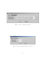
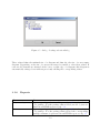
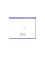
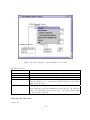
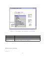
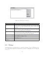
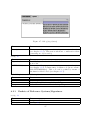
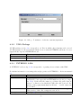
UML-Editor Reference Manual
The Art of Modeling. . .
Peter Hirzel
V1.0.4 (6th February 2004)
Contents
List of Figures
v
Preface
2
1 Regarding This Document
3
2 General Remarks
4
2.1
Installation . . . . . . . . . . . . . . . . . . . . . . . . . . . . . . . . . . .
4
2.2
License Terms . . . . . . . . . . . . . . . . . . . . . . . . . . . . . . . . . .
4
2.3
Mandator . . . . . . . . . . . . . . . . . . . . . . . . . . . . . . . . . . . .
5
2.4
Developer . . . . . . . . . . . . . . . . . . . . . . . . . . . . . . . . . . . .
5
2.5
Software applied
6
. . . . . . . . . . . . . . . . . . . . . . . . . . . . . . . .
3 User Interface
3.1
3.2
7
Menu Bar . . . . . . . . . . . . . . . . . . . . . . . . . . . . . . . . . . . .
7
3.1.1
File . . . . . . . . . . . . . . . . . . . . . . . . . . . . . . . . . . . .
9
3.1.2
Editing . . . . . . . . . . . . . . . . . . . . . . . . . . . . . . . . . .
9
3.1.3
View . . . . . . . . . . . . . . . . . . . . . . . . . . . . . . . . . . .
9
3.1.4
Formatting . . . . . . . . . . . . . . . . . . . . . . . . . . . . . . .
10
3.1.5
Extras . . . . . . . . . . . . . . . . . . . . . . . . . . . . . . . . . .
10
3.1.6
Reports . . . . . . . . . . . . . . . . . . . . . . . . . . . . . . . . .
12
3.1.7
Tools . . . . . . . . . . . . . . . . . . . . . . . . . . . . . . . . . . .
15
3.1.8
Window . . . . . . . . . . . . . . . . . . . . . . . . . . . . . . . . .
15
3.1.9
Help . . . . . . . . . . . . . . . . . . . . . . . . . . . . . . . . . . .
15
Symbol Bar . . . . . . . . . . . . . . . . . . . . . . . . . . . . . . . . . . .
16
ii
3.3
Navigation Pane . . . . . . . . . . . . . . . . . . . . . . . . . . . . . . . . .
16
3.4
Modeling Space . . . . . . . . . . . . . . . . . . . . . . . . . . . . . . . . .
16
3.4.1
Tool Bar . . . . . . . . . . . . . . . . . . . . . . . . . . . . . . . . .
17
3.5
Documentation Space . . . . . . . . . . . . . . . . . . . . . . . . . . . . . .
17
3.6
Log Pane . . . . . . . . . . . . . . . . . . . . . . . . . . . . . . . . . . . .
17
3.7
Status Bar . . . . . . . . . . . . . . . . . . . . . . . . . . . . . . . . . . . .
18
4 Modeling Elements
4.1
4.2
19
Class Diagram . . . . . . . . . . . . . . . . . . . . . . . . . . . . . . . . . .
19
4.1.1
Popup-Menu for the Diagram . . . . . . . . . . . . . . . . . . . . .
19
4.1.2
Popup-Menu of a Model Element . . . . . . . . . . . . . . . . . . .
22
Dialogs . . . . . . . . . . . . . . . . . . . . . . . . . . . . . . . . . . . . . .
26
4.2.1
Baskets of Reference Systems/Signatures . . . . . . . . . . . . . . .
27
4.2.2
UML-Package . . . . . . . . . . . . . . . . . . . . . . . . . . . . . .
28
4.2.3
INTERLIS 2-File . . . . . . . . . . . . . . . . . . . . . . . . . . . .
28
4.2.4
Model . . . . . . . . . . . . . . . . . . . . . . . . . . . . . . . . . .
30
4.2.5
Translation of the Model . . . . . . . . . . . . . . . . . . . . . . . .
31
4.2.6
Contract . . . . . . . . . . . . . . . . . . . . . . . . . . . . . . . . .
32
4.2.7
Topic . . . . . . . . . . . . . . . . . . . . . . . . . . . . . . . . . . .
33
4.2.8
Class . . . . . . . . . . . . . . . . . . . . . . . . . . . . . . . . . . .
34
4.2.9
Relationship . . . . . . . . . . . . . . . . . . . . . . . . . . . . . . .
37
4.2.10 Attributes . . . . . . . . . . . . . . . . . . . . . . . . . . . . . . . .
43
4.2.11 Role . . . . . . . . . . . . . . . . . . . . . . . . . . . . . . . . . . .
56
4.2.12 Domain . . . . . . . . . . . . . . . . . . . . . . . . . . . . . . . . .
56
4.2.13 Reference Systems/Symbology Baskets - Agreement . . . . . . . . .
59
4.2.14 Unit . . . . . . . . . . . . . . . . . . . . . . . . . . . . . . . . . . .
59
4.2.15 Line Form Type . . . . . . . . . . . . . . . . . . . . . . . . . . . . .
59
4.2.16 Run Time Parameter . . . . . . . . . . . . . . . . . . . . . . . . . .
61
4.2.17 Function . . . . . . . . . . . . . . . . . . . . . . . . . . . . . . . . .
61
4.2.18 View . . . . . . . . . . . . . . . . . . . . . . . . . . . . . . . . . . .
63
4.2.19 Graphic . . . . . . . . . . . . . . . . . . . . . . . . . . . . . . . . .
63
iii
A Technical Background
65
B UML
66
B.1 Specification . . . . . . . . . . . . . . . . . . . . . . . . . . . . . . . . . . .
66
B.1.1 UML Meta Model . . . . . . . . . . . . . . . . . . . . . . . . . . . .
66
C INTERLIS
67
C.1 Specification . . . . . . . . . . . . . . . . . . . . . . . . . . . . . . . . . . .
67
C.2 INTERLIS Compiler . . . . . . . . . . . . . . . . . . . . . . . . . . . . . .
67
D Formats
68
D.1 UML-editor-Format . . . . . . . . . . . . . . . . . . . . . . . . . . . . . . .
68
D.2 XML-Schema . . . . . . . . . . . . . . . . . . . . . . . . . . . . . . . . . .
68
D.3 INTERLIS-Compiler Configuration . . . . . . . . . . . . . . . . . . . . . .
71
D.4 INTERLIS Model File . . . . . . . . . . . . . . . . . . . . . . . . . . . . .
71
E Country-Specific Differences
74
Bibliography
75
Index
75
iv
List of Figures
3.1
UML-editor with example-model Roads . . . . . . . . . . . . . . . . . . .
8
3.2
dialog – Search/Replace . . . . . . . . . . . . . . . . . . . . . . . . . . . .
10
3.3
dialog – Options (tag paths) . . . . . . . . . . . . . . . . . . . . . . . . . .
11
3.4
dialog – Options (tag Class diagrams) . . . . . . . . . . . . . . . . . . . . .
11
3.5
dialog – Package selectiondialog . . . . . . . . . . . . . . . . . . . . . . . .
12
3.6
dialog – Report object catalog . . . . . . . . . . . . . . . . . . . . . . . . .
13
3.7
dialog – Report structure . . . . . . . . . . . . . . . . . . . . . . . . . . . .
14
3.8
log pane Select node (according to identification number) . . . . . . . . . .
18
4.1
Class diagram – Representation of packages . . . . . . . . . . . . . . . . .
20
4.2
Class diagram – Representation of classes with popup-menu for the diagram 21
4.3
Class diagram – General remarks about popup-menu model elements . . .
23
4.4
Class diagram – Special functions of a class . . . . . . . . . . . . . . . . . .
24
4.5
Class diagram – Special functions of an relatioship . . . . . . . . . . . . . .
25
4.6
dialog (tag description)
. . . . . . . . . . . . . . . . . . . . . . . . . . . .
26
4.7
dialog (tag Syntax ) . . . . . . . . . . . . . . . . . . . . . . . . . . . . . . .
27
4.8
dialog – Containers of reference systems/signatures . . . . . . . . . . . . .
28
4.9
dialog – UML-Paket . . . . . . . . . . . . . . . . . . . . . . . . . . . . . .
29
4.10 dialog – INTERLIS 2-file . . . . . . . . . . . . . . . . . . . . . . . . . . . .
29
4.11 dialog – Model (tag Detail ) . . . . . . . . . . . . . . . . . . . . . . . . . .
30
4.12 dialog – Model (tag Contract) . . . . . . . . . . . . . . . . . . . . . . . . .
31
4.13 dialog – Model (tag Import) . . . . . . . . . . . . . . . . . . . . . . . . . .
31
4.14 dialog – Translation of model . . . . . . . . . . . . . . . . . . . . . . . . .
32
v
4.15 dialog – Contract . . . . . . . . . . . . . . . . . . . . . . . . . . . . . . . .
32
4.16 dialog – Topic (tag Detail ) . . . . . . . . . . . . . . . . . . . . . . . . . . .
33
4.17 dialog – Topic (tag Dependency) . . . . . . . . . . . . . . . . . . . . . . .
34
4.18 dialog – Class (tag Detail ) . . . . . . . . . . . . . . . . . . . . . . . . . . .
35
4.19 dialog – Class (tag Attribute) . . . . . . . . . . . . . . . . . . . . . . . . .
35
4.20 dialog – class (tag Parameter ) . . . . . . . . . . . . . . . . . . . . . . . . .
36
4.21 dialog – class (tag Constraints) . . . . . . . . . . . . . . . . . . . . . . . .
36
4.22 dialog – relatioship (tag Detail ) . . . . . . . . . . . . . . . . . . . . . . . .
37
4.23 dialog – relatioship (tag Attributes) . . . . . . . . . . . . . . . . . . . . . .
38
4.24 dialog – relatioship (tag Roles) . . . . . . . . . . . . . . . . . . . . . . . .
38
4.25 dialog – relatioship (tag Constraints) . . . . . . . . . . . . . . . . . . . . .
39
4.26 Reflexive relations . . . . . . . . . . . . . . . . . . . . . . . . . . . . . . . .
40
4.27 Inherited relations
. . . . . . . . . . . . . . . . . . . . . . . . . . . . . . .
41
4.28 Multiple relations . . . . . . . . . . . . . . . . . . . . . . . . . . . . . . . .
42
4.29 Association with attributes . . . . . . . . . . . . . . . . . . . . . . . . . . .
43
4.30 dialog – Attribute (tag Detail ) . . . . . . . . . . . . . . . . . . . . . . . . .
44
4.31 dialog – Attribute (tag Derivation) . . . . . . . . . . . . . . . . . . . . . .
45
4.32 INTERLIS-basic type – Text orientation . . . . . . . . . . . . . . . . . . .
45
4.33 INTERLIS-basic type – String . . . . . . . . . . . . . . . . . . . . . . . . .
46
4.34 INTERLIS-basic type – enumeration . . . . . . . . . . . . . . . . . . . . .
47
4.35 INTERLIS-basic type – Numeric . . . . . . . . . . . . . . . . . . . . . . .
48
4.36 INTERLIS-basic type – Coordinate . . . . . . . . . . . . . . . . . . . . . .
50
4.37 INTERLIS-basic type – Basket . . . . . . . . . . . . . . . . . . . . . . . .
51
4.38 INTERLIS-basic type – Polyline . . . . . . . . . . . . . . . . . . . . . . . .
52
4.39 INTERLIS-basic type – Surface . . . . . . . . . . . . . . . . . . . . . . . .
53
4.40 INTERLISbasic type – Area tessellation . . . . . . . . . . . . . . . . . . .
55
4.41 INTERLIS-basic type – Domain definition . . . . . . . . . . . . . . . . . .
55
4.42 dialog – Role (tag Detail ) . . . . . . . . . . . . . . . . . . . . . . . . . . .
57
4.43 dialog – Domain . . . . . . . . . . . . . . . . . . . . . . . . . . . . . . . . .
58
4.44 dialog – Reference systems/Symbology baskets . . . . . . . . . . . . . . . .
60
4.45 dialog – Unit . . . . . . . . . . . . . . . . . . . . . . . . . . . . . . . . . .
60
vi
4.46 dialog – Line form
. . . . . . . . . . . . . . . . . . . . . . . . . . . . . . .
61
4.47 dialog – Run time parameter . . . . . . . . . . . . . . . . . . . . . . . . . .
62
4.48 dialog – Function . . . . . . . . . . . . . . . . . . . . . . . . . . . . . . . .
62
4.49 dialog – View . . . . . . . . . . . . . . . . . . . . . . . . . . . . . . . . . .
63
4.50 dialog – Graphic . . . . . . . . . . . . . . . . . . . . . . . . . . . . . . . .
64
1
Preface
The wish to enhance application of the model-based method motivated the creation of the
UML-editor .
In this sense the editor is unique, since it permits the modeling of UML/INTERLIS, i.e.
the synthesis of two standards within the scope of data-modeling.
INTERLIS is a specific form of UMLwhich permits the automatic derivation of different
formats (amongst others the XML-Schema).
This tool is an attempt to facilitate the application and thus the mastery of the very
complex matter of UML and INTERLIS thanks to a intuitive device and hence to render
it accessible to a greater number of users.
Thus we express due thanks to KOGIS because without their support this
UML/INTERLIS-editor could never have been achieved.
2
Chapter 1
Regarding This Document
• Chapter 2 gives general information concerning the UML-editor.
• Chapter 3 describes function and interface of the UML-editor.
• Chapter 4 describes specific model elements (objects) of the UML-editor.
3
Chapter 2
General Remarks
This reference manual has been conceived as an accompanying document for the UMLeditor. Thus it offers assistance in the use of functions and explain procedures of the tool.
At the same time it displays the technical possibilities of the editor in the modeling of
UML and INTERLIS.
Modeling with the UML-editor requires a certain knowledge in UML (see chapter B) [1] and
INTERLIS (see chapter C.1). Therefore we do not enter into these topics, because they
would be beyond the scope of this reference manual. You will find further information
concerning UML in the Internet and for INTERLIS there is an INTERLIS Reference
Manual [6] which offers ample explication concerning the use of INTERLIS by means of
practical examples.
In addition to this manual there is also an Introduction to the UML/INTERLIS-editor [7]
with a step-by-step explanation of modeling with the UML-editor.
2.1
Installation
For further instructions concerning the installation of the UML-editor see [7].
2.2
License Terms
This library is free software; you can redistribute it and/or modify it under the terms of
the GNU Lesser General Public License as published by the Free Software Foundation;
either version 2.1 of the License, or (at your option) any later version.
This library is distributed in the hope that it will be useful, but WITHOUT ANY WARRANTY; without even the implied warranty of MERCHANTABILITY or FITNESS FOR
A PARTICULAR PURPOSE. See the GNU Lesser General Public License for more details.
4
You should have received a copy of the GNU Lesser General Public License along with this
library; if not, write to the Free Software Foundation, Inc., 59 Temple Place, Suite 330,
Boston, MA 02111-1307 USA
2.3
Mandator
KOGIS c/o Bundesamt für Landestopographie
Seftigenstrasse 264, Postfach, CH-3084 Wabern
Telephon: +41 31 963 21 11 – Fax: +41 31 963 23 25
http://www.kogis.ch – E-mail: [email protected]
2.4
Developer
Eisenhut Informatik AG
Claude Eisenhut, Dipl. Informatik-Ingenieur HTL
Rosenweg 14, CH-3303 Jegenstorf
Telephon: +41 31 762 06 62 – Fax: +41 31 762 06 64
http://www.eisenhutinformatik.ch – E-Mail: [email protected]
Assistants:
5
softEnvironment
Peter Hirzel, Dipl. Informatik-Ingenieur HTL, NDS Umwelt
Rüttiweg 7, CH-3047 Bremgarten
Telephon: +41 79 746 67 40
http://www.softenvironment.ch – E-Mail: [email protected]
2.5
Software applied
• Java SDK (cf. http://java.sun.com)
• JHotDraw (Graphic) (cf. http://sourceforge.net/projects/jhotdraw)
• Apache Software Foundation (XML) (cf. http://www.apache.org)
6
Chapter 3
User Interface
On principle the UML-editor see fig. 3.1 represents the most important model elements
(see chapter 4) hierarchically in the navigation pane as a tree-structure (see chapter 3.3).
Some few elements (e.g. generalization, dependencies, syntax, etc.) do not really make
sense in the navigation pane and hence will be suppressed by the UML-editor . However
these model elements can still be maintained via the specification dialogs (see chapter 4.2) .
A possible element in the navigation pane is the class diagram (see chapter 4.1), which
permits graphic modeling. Thus it is possible to represent model elements from the navigation pane in a class diagram. The same model element may appear in several diagrams
in order to further visualize different aspects of the same data model. However graphic
representation is not possible for all model elements. Class diagrams can be generated in
the navigation pane and then opened in the modeling space (see chapter 3.4) .
3.1
Menu Bar
The menu list contains the names of the menus. By clicking a menu name a list of commands will appear, which in turn control a series of functions of the UML-editor.
7
Figure 3.1: UML-editor with example-model Roads
8
3.1.1
File
Function
New
Open. . .
Save
Save as. . .
Print. . .
Close
3.1.2
Editing
Function
Undo
Restore
Cut
Copy
Insert
Select all
Search/Replace. . .
3.1.3
Description
Generates a new model.
Opens a file dialog for the selection of a model file.
Saves the present model with the file name indicated.
Opens a file dialog for the saving of a file name with a different
name.
Opens a print dialog.
Closes the program.
Description
(At present this function is not implemented.)
(At present this function is not implemented.)
(At present this function is not implemented.)
(At present this function is not implemented.)
(At present this function is not implemented.)
(At present this function is not implemented.)
Opens a search-dialogsee fig. 3.2, to find elements that correspond to the search criteria. By selecting an element in the
search result list the relevant element is automatically selected
in the navigation pane .
View
Function
Look & Feel
Symbol lists
Status bar
Description
Various representation managers can be selected (independent
of platform).
The standard tool bar (see chapter 3.2) can be activated/ deactivated.
The status bar can be activated/ deactivated.
9
Figure 3.2: dialog – Search/Replace
3.1.4
Formatting
Function
Adjuste diagram
3.1.5
Description
The contents of the present diagram are automatically adjusted.
The function attempts to distribute the model elements as evenly
as possible in the diagram and at the same time to avoid as much
as possible crossings of lines. In general when using this function
it is necessary to manually improve this arrangement.
Extras
Function
Options. . .
Description
An options dialog see fig. 3.3, see fig. 3.4 is opened. The necessary configurations are stored in the file .umleditor in your
personal directory (${user.home}) .
Field
Work directory
Import directory
Field
Width (Standard)
Height (Standard)
Description
Standard directory for the saving and opening of files.
Standard directory for the import of data.
Description
Standard width for new class diagrams.
Standard height for new class diagrams.
10
Figure 3.3: dialog – Options (tag paths)
Figure 3.4: dialog – Options (tag Class diagrams)
11
Figure 3.5: dialog – Package selectiondialog
These values define the minimal size of a diagram and thus also the size of a new empty
diagram. Depending on the size of your screen it may be sensible to alter these values. If
some model elements are situated at the lower or right edge of a diagram, this diagram is
automatically enlarged even without previously altering the corresponding values.
3.1.6
Reports
Function
Object catalog. . .
Structure. . .
Description
Opens a package selection dialog see fig. 3.5 for the selection
of a package. For the package thus selected, model objects are
listed in an HTML-report see fig. 3.6.
Opens a package selection dialog see fig. 3.5 for the selection
of a package. For the package thus selected the corresponding
package structure is generated in an HTML-report see fig. 3.7.
12
Figure 3.6: dialog – Report object catalog
13
Figure 3.7: dialog – Report structure
14
3.1.7
Tools
INTERLIS
Function
Import. . .
Import groups. . .
Export. . .
Export XML-Schema
...
Model check
Description
Opens a filedialogin order to import INTERLIS-model files into
the model (see chapter D.4).
(At present this function is not implemented.)
Generates the INTERLIS-model files (see chapter D.4) according
to the present model in the work directory (see chapter 3.1.5).
Opens a file-dialogfor the export of the XML-Schema (XSD)
(see chapter D.2). The XML-Schema thus generated describes
the transfer format.
The model is examined by means of the INTERLIScompiler (see
chapter C.2). Possible errors appear in the log pane with an
identification number (see chapter 3.6).
XMI/ROSE
Function
Import. . .
3.1.8
Window
Function
Cascade
Distribute
3.1.9
Description
Opens a file dialogto import a model file exported with RationalRose via XMI .
Description
Several windows in the modeling space will be super-positioned
one behind the other.
Several windows in the modeling space will be super-positioned
one below the other.
Help
Function
Help. . .
Info. . .
Description
Opens a help-line in a browser.
Opens an info dialog with information concerning the program.
15
3.2
Symbol Bar
Depending on the context, individual functions are activated or deactivated (by activating the symbols in the symbol list). By positioning the mouse cursor on a symbol, the
corresponding description of the function appears in text form.
New (see chapter 3.1.1).
Open. . . (see chapter 3.1.1).
Save (see chapter 3.1.1).
Print (see chapter 3.1.1).
3.3
Navigation Pane
The navigation pane represents the entire model as a tree structure . Thus the user may see
how the model is organized and the view can be adjusted to the current needs of the user
by opening/closing sub-trees A context-sensitive menu will show the possible functions for
each selected model element in the tree:
Function
Description
New
Permits the inserting of a new model element. Depending on
the selection various elements are available (see chapter 4).
Modify. . .
Opens the specification dialog for the corresponding element
model element (see chapter 4.2).
Activate diagram
Opens or displays the selected diagram in the foreground within
the modeling range.
Sort
Arranges the tree structure according to the possible selection,
criterias being Name or Type/Name.
Print. . .
Opens a print dialog.
Delete (in the model) Deletes the selected model element from the model.
Rename
Permits direct renaming of the selected element.
Insert in diagram
Inserts the selected model element into the momentarily active
diagram .
3.4
Modeling Space
In the modeling space diagrams (see chapter 4.1) that typically display a prominent detail
from the model can be represented in their own (internal) windows.
16
3.4.1
Tool Bar
The tool bar is dynamically adjusted to the currently selected diagram (see chapter 4.1),
i.e. the tools that are admissible for the corresponding diagram type are automatically
displayed and activated.
The following tools are supported by the UML-editor :
Enlarges the current diagram.
Reduces the current diagram.
Permits the selection of a model element.
Permits inserting of a note.
Permits connecting a note with another model element(node).
Permits inserting of a package.
Permits inserting of a class .
Permits connecting two classes by means of a relationship.
Permits the creation of a reflexive relationship of a class.
Permits the inheritance (generalization) between two model elements.
Permits the creation of a dependency between two model elements.
3.5
Documentation Space
The documentation view displays descriptions concerning an model element , e.g. by means
of selection:
• in the navigation pane(see chapter 3.3)
• in the current diagram
A popup menu permits all common editing operations (see chapter 3.1.2).
3.6
Log Pane
The log pane see fig. 3.8 features run-time messages (e.g. when saving the model or during
model check (see chapter 3.1.7)). Depending on the selection the following functions of the
popup menu are possible:
17
Figure 3.8: log pane Select node (according to identification number)
Function
Delete
Copy
Select all
Make up lines
Save as. . .
Select node
3.7
Description
Deletes the entire display in the log pane.
Inserts the selected messages in the copy buffer of the system.
Selects all messages.
Messages that are longer than the current window width are
made up into two lines by the UML-editor .
Permits the saving of all messages in the log pane of a file.
Applies only to special messages with identification number.
This function selects the model element concerned by this message in the navigation pane.
Status Bar
The status bar is set up in three sections:
• Left box indicates which tool from the tool bar is currently activated.
• Middle box (At present this function is not implemented.)
• Right box (At present this function is not implemented.)
18
Chapter 4
Modeling Elements
Hereafter we describe model elements that can be modeled by means of the UML-editor
. Based upon the language definition and resulting rules of INTERLIS there is a valid
selection of sub-elements for each model element , These will be automatically supported
by the UML-editor .
This is the particular strong point of the UML-editor, a user need not worry whether he
is developping a valid model or not. Whatever is rendered possible by the editor, is also
valid within the scope of UML and INTERLIS . Special cases can always be verified by
means of the INTERLIS-compiler (see chapter 3.1.7).
4.1
Class Diagram
The class diagrams strictly respect the rules of UML (see chapter B). All possible tools
are automatically activated when opening a class diagram in the tool bar (see chapter
3.4.1).
A typical use of class diagrams is the representation of packages see fig. 4.1 or classes see
fig. 4.2:
4.1.1
Popup-Menu for the Diagram
The following functions, affecting the entire diagram , are at your disposal:
19
Figure 4.1: Class diagram – Representation of packages
20
Figure 4.2: Class diagram – Representation of classes with popup-menu for the diagram
21
Function
Display role
Display cardinality
Display association
names
Display attributes in
classes
Display type of attribute
Display cardinality of
attributes
Display link node of
associations
Print. . .
Save. . . in
diagram
file
Automatic reorganization
4.1.2
Description
Represents the roles (see chapter 4.2.11) of a relationship or not.
Roles are represented with a preceding plus (e.g. +Street see
fig. 3.1).
Represents the cardinalities of relationships or not (e.g. 0..* see
fig. 3.1).
Represents the names of all relationships in the diagram dar or
not.
Represents the attributes of all classes in the diagram or not.
Represents the data type for all attributes displayed in all classes
in the diagram or not.
Represents the cardinality of all attributes displayed in all classes
in the diagram or not .
The link node is an “artificial device”, that enables graphic links
between particular cases of relationships (see chapter 4.2.9) in
the diagram .
Opens a print dialog for the printing of the diagram.
Opens a file-dialog for the saving of the diagram.
Automatic reorganization of the contents of a diagram.
Popup-Menu of a Model Element
General Functions
For each model element the following general functions are available see fig. 4.3:
Function
Modify. . .
Selecting in the navigation pane
Description
Opens the specification dialog (see chapter 4.2) for a model element.
Indicates the selected graphic object in the navigation pane.
Sub-menu Formatting:
Function
Font type. . .
Line color. . .
Fill-in color. . .
Description
(At present this function is not implemented.).
Opens a color dialog for the selection of a line color (e.g. for the
coloring of associations).
Opens a color dialog for the selection of a fill-in color (e.g. for
the coloring of class symbols).
22
Figure 4.3: Class diagram – General remarks about popup-menu model elements
23
Figure 4.4: Class diagram – Special functions of a class
Sub-menu Editing:
Function
Cut
Copy
Paste
Delete
Delete in the model
Description
(At present this function is not implemented.).
(At present this function is not implemented.).
(At present this function is not implemented.).
The selected model element is only graphically deleted in the
current diagram, i.e. it remains in the navigation pane (and
thus in the model).
The selected model element is deleted graphically in the current diagram as well as definitively in the model. In addition
all model dependencies are deleted (e.g. Roles in classes with
connected associations).
Class-specific functions
see fig. 4.4
24
Figure 4.5: Class diagram – Special functions of an relatioship
Function
New attribute
Hide attributes
Display inherited attributes
Description
Adds a new attribute (see chapter 4.2.10) to the class.
Activates/ Deactivates representation of attributes for this class.
In addition to the attributes defined in this class, the attributes
of the basic class(es) are also displayed.
Relation-specific functions
see fig. 4.5
25
Figure 4.6: dialog (tag description)
Function
Association
Aggregation
Composition
Display role
Display cardinality
Display name of association
4.2
Description
Defines the direction of navigation towards a role (see chapter
4.2.11) on the corresponding relatioship. In accordance with
UML this is represented optically by an open arrow in the class
diagram .
Characterizes the role (see chapter 4.2.11) of an relatioship as aggregation. In accordance with UML this is represented optically
with a void rhombus in the class diagram .
Characterizes the role (see chapter 4.2.11) of an relatioship as
composition. In accordance with UML this is represented optically with a filled in rhombus in the class diagram .
Activates / Deactivates the role name (see chapter 4.2.11) of a
relationship (see chapter 4.1.1).
Represents the cardinality of the roles (see chapter 4.2.11) of an
relatioship or not .
Represents the name of an relatioship or not.
Dialogs
On principle there is a specific dialog for each model element to view or modify the properties of this element. Each model element-dialog features a minimum of the following tabs
see fig. 4.6:
26
Figure 4.7: dialog (tag Syntax )
Field
Description
Description
Text entry with popup-menu featuring common text functions
(see chapter 3.1.2). This text is taken into consideration when
generating an object catalog
see fig. 4.7
Field
Depends of
INTERLIS Syntax
Description
Possible dependencies of other Model elements can be selected
from a list.
Text entry with popup-menu featuring common text functions
(see chapter 3.1.2). Permits entry of syntax code (in accordance
with INTERLISrules). This code can be verified by means of
the function Model check (see chapter 3.1.7).
Each dialog features the following functions:
Function
OK
Cancel
Accept
4.2.1
Description
Saves all modifications and closes dialog.
Rejects all modifications and closes dialog.
Saves all modifications without closing dialog.
Baskets of Reference Systems/Signatures
see fig. 4.8
Field
File name
Description
Description
Assigns an XML-file .
(see fig. 4.6).
27
Figure 4.8: dialog – Containers of reference systems/signatures
4.2.2
UML-Package
A UML-package see fig. 4.9 corresponds to a folder, in which other elements can be stored.
A UML-package is a model element which does not exist in INTERLIS and hence does not
appear in the exported INTERLIS-model.
Field
Name
Description
4.2.3
Description
Name of the UML-package
(see fig. 4.6).
INTERLIS 2-File
A INTERLIS 2-file see fig. 4.10 corresponds to a package in accordance with UML.
For further information concerning rules and properties see INTERLIS 2 – Referencemanual
2.3.
Field
Description
Table
Lists language and corresponding file names. A model element
INTERLIS 2-file represents an INTERLIS-model file (see chapter D.4). If the field file name is a relative file path, then it
refers to a directory, in which the UML-editor file is stored. By
means of the popup-menu-function Modify. . . a table entry can
be modified.
Linguistic version
We refer to the version of the INTERLIS-specification applied.
This version of the editor supports version 2.2.
Description
(see fig. 4.6).
28
Figure 4.9: dialog – UML-Paket
Figure 4.10: dialog – INTERLIS 2-file
29
Figure 4.11: dialog – Model (tag Detail )
4.2.4
Model
A model see fig. 4.11 corresponds to a package) in accordance with UML.
For further information concerning rules and properties see INTERLIS 2 – Referencemanual
2.5.1.
Field
Description
Name
Name of the model
Type
Characterization (possible options being types, reference systems, symbologies or unlimited ).
Description
(see fig. 4.6).
Original language
Initial language of the Model .
Translation (table)
A translation dialog can be opened via a popup-menu (see chapter 4.2.5). All translations concerning the Model are listed in
the table.
see fig. 4.12
Field
Contract (Table)
Description
Via popup-menu you can open a contract dialog (see chapter
4.2.6). In this table all authors of contracts are listed.
30
Figure 4.12: dialog – Model (tag Contract)
Figure 4.13: dialog – Model (tag Import)
see fig. 4.13
Field
Import (Tabelle)
4.2.5
Description
Via popup-menu and by means of a assignation dialog other models can be assigned and administered. In the table all imported
models are listed. Import relationships can be represented in a
package diagram.
Translation of the Model
At present multilingual models are not supported by the UML-editor .
For further information concerning rules and properties see INTERLIS 2 – Referencemanual
31
Figure 4.14: dialog – Translation of model
Figure 4.15: dialog – Contract
2.5.1. see fig. 4.14
Field
Language
Basic language
4.2.6
Description
Target language of the translation.
Initial language before the translation.
Contract
For further information concerning rules and properties see INTERLIS 2 – Referencemanual
1.7. see fig. 4.15
Field
Editor
Description
Description
Author of a contract.
(see fig. 4.6).
32
Figure 4.16: dialog – Topic (tag Detail )
4.2.7
Topic
A topic see fig. 4.16 corresponds to a package in accordance with UML.
For further information concerning rules and properties see INTERLIS 2 – Referencemanual
2.5.2.
Field
Description
Name
Name of the topic
Type
Characterization (by views or unlimited ).
Description
(see fig. 4.6).
abstract
Defines a model element as abstract or not.
final
Defines a model element as final or not.
Extends
Permits the selection of model element possibly to be extended
from a list of model elements suitable for specialization (list is
automatically generated by the UML-editor).
see fig. 4.17
Field
Dependency (Table)
Description
Via popup-menu and by means of an assignation dialog other
topics can be assigned and processed. In the table all dependent
topics are listed. The dependency relationships can be represented in a package diagram.
33
Figure 4.17: dialog – Topic (tag Dependency)
4.2.8
Class
A class see fig. 4.18 describes similar objects by means of attributes .
For further information concerning rules and properties see INTERLIS 2 – Referencemanual
2.5.3.
Field
Description
Name
Name of the class
Description
(see fig. 4.6).
abstract
Defines a model element as abstract or not.
final
Defines a model element as final or not.
Extends
Permits the selection of model element possibly to be extended
from a list of model elements suitable for specialization (list is
automatically generated by the UML-editor).
Typ
A class can either be characterized as a class (Default) or as a
structure.
see fig. 4.19
Field
Attribute (Tabelle)
Description
Via popup-menu a list of attributes (see chapter 4.2.10) can be
processed. All defined attributes are listed in the table.
see fig. 4.20
Field
Parameters
Description
Several Parameters in the form of syntax codes can be indicated
(see fig. 4.7) . Use the symbol bar below the syntax field to
facilitate when browsing, for input and deleting of Parameters.
see fig. 4.21
34
Figure 4.18: dialog – Class (tag Detail )
Figure 4.19: dialog – Class (tag Attribute)
35
Figure 4.20: dialog – class (tag Parameter )
Figure 4.21: dialog – class (tag Constraints)
36
Figure 4.22: dialog – relatioship (tag Detail )
Field
Constraints
4.2.9
Description
Several Constraints in the form of syntax codes can be indicated
(see fig. 4.7) . Use the symbol bar below the syntax field to
facilitate when browsing, for input and deleting of Constraints.
Relationship
An relatioship see fig. 4.22 describes similar connections between individual objects.
For further information concerning rules and properties see INTERLIS 2 – Referencemanual
2.7.
37
Figure 4.23: dialog – relatioship (tag Attributes)
Figure 4.24: dialog – relatioship (tag Roles)
Field
Name
Description
abstract
final
Extends
Derived from
Description
Name of the association
(see fig. 4.6).
Defines a model element as abstract or not.
Defines a model element as final or not.
Permits the selection of model element possibly to be extended
from a list of model elements suitable for specialization (list is
automatically generated by the UML-editor).
From a list an model element (in general a view) can be selected,
from which the relatioship is to be derived.
see fig. 4.23
Field
Attributes (Table)
Description
Via popup-menu a list of attributes (see chapter 4.2.10) can be
processed. In the table all defined attributes can be listed.
see fig. 4.24
Field
Roles (Table)
Description
Via the table all defined rolles are listed.
see fig. 4.25
38
Figure 4.25: dialog – relatioship (tag Constraints)
Field
Constraints
Description
Several Constraints in the form of syntax codes can be indicated
(see fig. 4.7) . Use the symbol bar below the syntax field to
facilitate when browsing, for input and deleting of Constraints.
There are a few special cases of associations (besides the common binary association),
which the UML-editor supports graphically and thus also in the model.
Reflexive relations
see fig. 4.26
Inherited associations
see fig. 4.27
Hint:
• For graphic modelling it is necessary to visualize first the link knots in the class
diagram (void rhombus in the middle of the association) (see chapter 4.1).
Multiple relations
see fig. 4.28
Hint:
39
Figure 4.26: Reflexive relations
40
Figure 4.27: Inherited relations
41
Figure 4.28: Multiple relations
42
Figure 4.29: Association with attributes
• For graphic modelling it is necessary to visualize first the link knots in the class
diagram (void rhombus in the middle of the association) (see chapter 4.1).
Association with attributes
see fig. 4.29
Hint:
• Via the specification dialog Attributes can be processed in the tab Attribute . The
representation in the class diagram ensues automatically.
4.2.10
Attributes
An attribut (engl. feature or also property) see fig. 4.30 is a data element of a class. An
attribute possesses both name and data type. As data types all types that have been
defined by INTERLIS are at your disposal.
43
Figure 4.30: dialog – Attribute (tag Detail )
Attributes can be processed in three different ways, these being navigation pane (see
chapter 3.3), class diagram see chapter 4.1.2 or this dialog.
For further information concerning rules and properties see INTERLIS 2 – Referencemanual
2.6.
Field
Description
Name
Name of the Attributes
Typ
Depending on the type selected specific information can be indicated in the tab (see below).
Description
(see fig. 4.6).
abstract
Defines a model element as abstract or not.
final
Defines a model element as final or not.
specialized
Defines a model element as specialized or not.
Cardinality
Selection of the cardinality is possible in a list. Attributes with
an anonymous domain can only possess cardinality 0..1 or 1. Attributes which refer to a domain definition, can have maximum
cardinality greater than 1.
see fig. 4.31
44
Figure 4.31: dialog – Attribute (tag Derivation)
Figure 4.32: INTERLIS-basic type – Text orientation
Field
Derivation
Description
Permits the indication of a syntax code (see fig. 4.7) , e.g. a
function call or a constant.
Depending on the type the representation of information in the tab varies:
Boolean
For further information concerning rules and properties see INTERLIS 2 – Referencemanual
2.8.4.
For the type Boolean there is no special view.
Text Orientation
For further information concerning rules and properties see INTERLIS 2 – Referencemanual
2.8.3. see fig. 4.32
Field
Type
Description
Characterizes the text orientation Horizontal or Vertical.
45
Figure 4.33: INTERLIS-basic type – String
String
For further information concerning rules and properties see INTERLIS 2 – Referencemanual
2.8.1. see fig. 4.33
Field
Type
Max. Length (only
for the selection of
“string”)
Description
Characterizes the string as Undefined, String (Default),
INTERLIS-name or Uniform Resource Identifier (URI).
entry of a whole number for limiting the maximum string length.
Enumeration
With the type enumeration see fig. 4.34 it is possible to define enumerations or subenumerations as a tree-structure in the field elements. Furthermore each enumeration
element can be commented upon in the domain element description.
For further information concerning rules and properties see INTERLIS 2 – Referencemanual
2.8.2.
Field
Description
Type
Charakterizes the string as Undefined (Default), Ordered, oder
Circular.
Elements
A popup-menu permits the processing of enumerations in a tree
structure (by means of sub-enumeration).
Element description
for each enumeration elementa corresponding comment can be
formulated (see fig. 4.6).
46
Figure 4.34: INTERLIS-basic type – enumeration
47
Figure 4.35: INTERLIS-basic type – Numeric
Numeric
For further information concerning rules and properties see INTERLIS 2 – Referencemanual
2.8.5. see fig. 4.35
48
Field
Domain
Cirkular
Unit
Type
Reference system
Description
Characterizes the numeric domain as an Undefined domain (Default), as a Defined domain (permits the entry of a minimal or
maximal domain as a value with flowing comma, whereby accuracy can be defined via the selection list), or as a structured
number.
Defines a model element as Cirkular or not.
A list permits the selection of a unit existing in the model (see
chapter 4.2.14). This list is automatically generated by the
UML-editor.
Characterizes the type as Undefined (Default), as clockwise or
as anti-clockwise.
Permits the indication of syntax code (see fig. 4.7) .
Coordinate
For further information concerning rules and properties see INTERLIS 2 – Referencemanual
2.8.7. see fig. 4.36
Field
Dimensions
Circular
1/2/3D (Numeric)
Rotation
Main axis
PI-main axis
Description
Defines the number of dimensions of the coordinate.
Defines a model element as Circular or not.
For each dimension it is possible to indicate a numeric value (see
chapter 4.2.10) moeglich.
Defines a model element as Rotation or not.
Provided the rotation has been determined, the main axis can
be defined.
Provided the rotation has been determined, the PI-main axis
can be defined.
Basket
For further information concerning rules and properties see INTERLIS 2 – Referencemanual
2.8.9. see fig. 4.37
Field
Type
According to
Description
Characterizes the type as Undefined (Default), Data basket,
Sicht-Behaelter, Basis-Behaelter fuer Grafik oder als GrafikBehaelter.
Permits the indication of a topic (see chapter 4.2.7). This list is
automatically generated by the UML-editor.
49
Figure 4.36: INTERLIS-basic type – Coordinate
50
Figure 4.37: INTERLIS-basic type – Basket
51
Figure 4.38: INTERLIS-basic type – Polyline
Polyline
For further information concerning rules and properties see INTERLIS 2 – Referencemanual
2.8.11.2. see fig. 4.38
Field
Vertices
Overlap
Directed
Straight
Circle arc
Line type (table)
Description
Permits the assignation of a domain (see chapter 4.2.12) for the
vertices of a polyline. This list is automatically generated by the
UML-editor.
Permits the entry of a decimal value (definition of accuracy by
means of selection list).
Defines the polyline as directed or not.
Defines straights as admissible line types.
Defines circle arcs as admissible line types.
A popup-menu of the table permits the assiognation of line types
(see chapter 4.2.15).
52
Figure 4.39: INTERLIS-basic type – Surface
Surface
For further information concerning rules and properties see INTERLIS 2 – Referencemanual
2.8.12.2. see fig. 4.39
53
Field
Vertices
Overlap
Line attributes
Straight
Circle arc
Line type (table)
Description
Permits the assignation of a domain (see chapter 4.2.12) for the
vertices of the surfaces. This list is automatically generated by
the UML-editor.
Permits the enty of a decimal value (definition of accuracy by
means of a selection list).
Permits the selection of a structure (see chapter 4.2.8) for the
line attributes. This list is automatically generated by the UMLeditor.
Defines straights as admissible line types.
Defines circle arcs as admissible line types.
A popup-menu of the table permits the assiognation of line types
(see chapter 4.2.15).
Area Tessellation
For further information concerning rules and properties see INTERLIS 2 – Referencemanual
2.8.12.3. see fig. 4.40
Field
Vertices
Overlap
Line attributes
Straights
Circle arcs
Line type (table)
Description
Permits the assignation of a domain (see chapter 4.2.12) for the
vertices of the area tessellation. This list is automatically generated by the UML-editor.
Permits the entry of a decimal value (Definition of accuracy by
means of a selection list).
Permits the selection of a structure (see chapter 4.2.8) for the
line attributes. This list is automatically generated by the UMLeditor.
Defines straights as admissible line types.
Defines circle arcs as admissible line types.
A popup-menu of the table permits the assiognation of line types
(see chapter 4.2.15).
Domain definition
For further information concerning rules and properties see INTERLIS 2 – Referencemanual
2.6.2. see fig. 4.41
Field
Name
Description
Permits the assignation of the domain (see chapter 4.2.12). This
list is automatically generated by the UML-editor.
54
Figure 4.40: INTERLISbasic type – Area tessellation
Figure 4.41: INTERLIS-basic type – Domain definition
55
4.2.11
Role
A role see fig. 4.42 is on end of a relationship. When dealing with a relationship between
the class school and the class person, teacher would be a possible role for a Person.
For further information concerning rules and properties see INTERLIS 2 – Referencemanual
Field
Description
Name
Name of the role
Type
Permits the indication if Association (Default), Aggregation or
Composition (
For further information concerning rules and properties see INTERLIS 2 – Referencemanual 2.7.2.). Depending on the selection the specific representation (rhomboid) ensues in the class
diagram in accordance with UML.
Description
(see fig. 4.6).
abstract
Defines a model element as abstract or not.
final
Defines a model element as final or not.
Specialised
Defines a model element as Specialised or not.
Ordered
Defines a model element as Ordered or not.
2.7.
Navigierbar
Defines a model element as Navigierbar or not.
Cardinality
(
For further information concerning rules and properties see INTERLIS 2 – Referencemanual 2.7.3.)
Classes concerned
Permits the selection of the class concerned with this Role (see
chapter 4.2.8). This list is automatically generated by the UMLeditor.
Constraints (Table)
Permits the assignation of corresponding classes (see chapter
4.2.8 and
For further information concerning rules and properties see INTERLIS 2 – Referencemanual 2.7.5.).
Type of reference
Permits the selection of the Role as Association (Default), Structure or Reference.
4.2.12
Domain
For further information concerning rules and properties see INTERLIS 2 – Referencemanual
2.8. see fig. 4.43
56
Figure 4.42: dialog – Role (tag Detail )
57
Figure 4.43: dialog – Domain
58
Field
Name
Typ
Description
abstract
final
Mandatory
Specialised
4.2.13
Description
Name of the domain
Depending on the type selected it is possible to indicate special
information in a tab (analogous see chapter 4.2.10).
(see fig. 4.6).
Defines a model element as abstract or not.
Defines a model element as final or not.
Defines a model element as Mandatory or not.
Permits the selection of a basic -domain .
Reference Systems/Symbology Baskets - Agreement
For
further
information
concerning
rules
and
properties
see
2.10.
see
fig.
4.44
INTERLIS
2
–
Referencemanual
Field
Description
Name
Name of the reference system/symbology basket - Agreement
Basket identification Indication of the BID.
(BID)
Type
Selection as symbology basket (Default) or reference system basket.
Description
(see fig. 4.6).
Definition
(see fig. 4.7)
4.2.14
Unit
For further information concerning rules and properties see INTERLIS 2 – Referencemanual
2.9. see fig. 4.45
Field
Name (Abbreviation
Description
Description
Depends on
Syntax
4.2.15
Description
Abbreviation of the Unit.
Name written in full of the Unit.
(see fig. 4.6).
Selection of dependency on another model element. This list is
automatically generated by the UML-editor..
(see fig. 4.7).
Line Form Type
For further information concerning rules and properties see INTERLIS 2 – Referencemanual
2.8.11.3. see fig. 4.46
59
Figure 4.44: dialog – Reference systems/Symbology baskets
Figure 4.45: dialog – Unit
60
Figure 4.46: dialog – Line form
Field
Name
Description
Syntax
4.2.16
Description
Name of the Line form
(see fig. 4.6).
(see fig. 4.7).
Run Time Parameter
For further information concerning rules and properties see INTERLIS 2 – Referencemanual
2.11. see fig. 4.47
Field
Name
Description
Syntax
4.2.17
Description
Name of Run time parameter
(see fig. 4.6).
(see fig. 4.7).
Function
For further information concerning rules and properties see INTERLIS 2 – Referencemanual
2.14. see fig. 4.48
Field
Name
Description
Syntax
Description
Name of the function
(see fig. 4.6).
(see fig. 4.7).
61
Figure 4.47: dialog – Run time parameter
Figure 4.48: dialog – Function
62
Figure 4.49: dialog – View
4.2.18
View
For further information concerning rules and properties see INTERLIS 2 – Referencemanual
2.15. see fig. 4.49
Field
Name
Description
Syntax
4.2.19
Description
Name of the view
(see fig. 4.6).
(see fig. 4.7).
Graphic
For further information concerning rules and properties see INTERLIS 2 – Referencemanual
2.16. see fig. 4.50
Field
Name
Description
Syntax
Description
Name of the graphic
(see fig. 4.6).
(see fig. 4.7).
63
Figure 4.50: dialog – Graphic
64
Appendix A
Technical Background
The UML-editor is based entirely on the UML meta model of the Object Managment
Group (OMG). Thus it is guaranteed that all models created with this UML-editor will be
compatible in all respects of the UML-specification (see chapter B.1). Any upgrade of the
UML-meta model design on the part of OMG should be possible with very little effort.
An INTERLIS-Plugin extends and concretizes the UML-meta model by adding INTERLISelements. Thus the UML-editor becomes the ideal tool for users that intend to
model INTERLIS (see chapter C.1) (i.e. geomatic engineers).
The UML-editor has been entirely conceived in Java (s. http://java.sun.com). Java was
considered the ideal device for this project because besides other advantages it offers the
possibility to implement the object-oriented design of UML and INTERLIS . Furthermore
Java is deemed platform-independent. The present release is based upon JRE 1.3, but on
principle it can also be applied in improved versions of the Virtual Machine (VM).
For its greater part the model has been designed with Rational Rose (a commercial UMLeditor) and then generated with a specially extended Java-Code-Generator. Thus the
design will always be up-to-date with the source code.
This document was drafted in LATEX.
65
Appendix B
UML
OMG’s Unified Modeling Language™(UML) is of use when specifying, visualizing and
documenting models in connection with software systems (including their structure and
design).
UML can be used in business-modeling as well as in non-software-systems. In the present
case UML is especially adapted to the demands of modeling of INTERLIS-data models.
B.1
Specification
The present version of the UML-editor is determined by the UML Specification Version
1.4.
It is possible to look into detailed information concerning the contents of the UML specification under http://www.omg.org/uml .
B.1.1
UML Meta Model
OMG makes the UML meta modell available in the form of a download .
The UML-specification in accordance with OMG is very extensive. In the present version
of the UML-editor only those possibilities have been implemented with priority which are
relevant within the scope of modeling with INTERLIS.
66
Appendix C
INTERLIS
C.1
Specification
The present version of the UML-editor is in accordance with the INTERLIS specification
version 2.
For more detailed information concerning this reference manual see http://www.
interlis.ch
C.2
INTERLIS Compiler
The INTERLIScompiler developped by Eisenhut Informatik AG (see chapter 2.4) on behalf
of KOGIS (cf. http://www.interlis.ch) is an integrated component of the UML-editor
and permits e.g. the examination of INTERLIS language definitions within an INTERLIS
model (see chapter 3.1.7).
67
Appendix D
Formats
D.1
UML-editor-Format
The UML-editor uses its own format for saving (see chapter 3.1.1) models with the ending
.uml.
D.2
XML-Schema
ASCII-Code nach Export of an XML-Schema (see chapter 3.1.7) into a file with suffix .XSD.
<xsd:schema xmlns:xsd="http://www.w3.org/2001/XMLSchema"
xmlns="http://www.interlis.ch/INTERLIS2.2"
targetNamespace="http://www.interlis.ch/INTERLIS2.2"
elementFormDefault="qualified" attributeFormDefault="unqualified">
<xsd:element name="TRANSFER" type="Transfer"/>
<xsd:complexType name="Transfer">
<xsd:sequence>
<xsd:element name="HEADERSECTION" type="HeaderSection"/>
<xsd:element name="DATASECTION" type="DataSection"/>
</xsd:sequence>
</xsd:complexType>
<xsd:complexType name="HeaderSection">
<xsd:sequence>
<xsd:element name="ALIAS" type="Alias"/>
<xsd:element name="COMMENT" type="xsd:anyType" minOccurs="0"/>
</xsd:sequence>
<xsd:attribute name="VERSION" type="xsd:decimal" use="required" fixed="2.2"/>
<xsd:attribute name="SENDER" type="xsd:string" use="required"/>
68
</xsd:complexType>
<xsd:complexType name="Alias">
<xsd:sequence>
<xsd:element name="ENTRIES" type="Entries" minOccurs="0" maxOccurs="unbounded"/>
</xsd:sequence>
</xsd:complexType>
<xsd:complexType name="Entries">
<xsd:sequence>
<xsd:choice maxOccurs="unbounded">
<xsd:element name="TAGENTRY" type="Tagentry"/>
<xsd:element name="VALENTRY" type="Valentry"/>
<xsd:element name="DELENTRY" type="Delentry"/>
</xsd:choice>
</xsd:sequence>
<xsd:attribute name="FOR" type="xsd:string" use="required"/>
</xsd:complexType>
<xsd:complexType name="Tagentry">
<xsd:attribute name="FROM" type="xsd:string" use="required"/>
<xsd:attribute name="TO" type="xsd:string" use="required"/>
</xsd:complexType>
<xsd:complexType name="Valentry">
<xsd:attribute name="ATTR" type="xsd:string" use="required"/>
<xsd:attribute name="FROM" type="xsd:string" use="required"/>
<xsd:attribute name="TO" type="xsd:string" use="required"/>
</xsd:complexType>
<xsd:complexType name="Delentry">
<xsd:attribute name="TAG" type="xsd:string" use="required"/>
</xsd:complexType>
<xsd:complexType name="BasketValue">
<xsd:attribute name="TOPIC" type="xsd:string" use="required"/>
<xsd:attribute name="KIND" type="xsd:string" use="required"/>
<xsd:attribute name="BID" type="xsd:string" use="required"/>
</xsd:complexType>
<xsd:complexType name="CoordValue">
<xsd:sequence>
<xsd:element name="C1">
<xsd:simpleType>
<xsd:restriction base="xsd:decimal"/>
</xsd:simpleType>
</xsd:element>
<xsd:element name="C2" minOccurs="0">
<xsd:simpleType>
<xsd:restriction base="xsd:decimal"/>
</xsd:simpleType>
</xsd:element>
69
<xsd:element name="C3" minOccurs="0">
<xsd:simpleType>
<xsd:restriction base="xsd:decimal"/>
</xsd:simpleType>
</xsd:element>
</xsd:sequence>
</xsd:complexType>
<xsd:complexType name="ArcPoint">
<xsd:sequence>
<xsd:element name="C1">
<xsd:simpleType>
<xsd:restriction base="xsd:decimal"/>
</xsd:simpleType>
</xsd:element>
<xsd:element name="C2">
<xsd:simpleType>
<xsd:restriction base="xsd:decimal"/>
</xsd:simpleType>
</xsd:element>
<xsd:element name="C3" minOccurs="0">
<xsd:simpleType>
<xsd:restriction base="xsd:decimal"/>
</xsd:simpleType>
</xsd:element>
<xsd:element name="A1">
<xsd:simpleType>
<xsd:restriction base="xsd:decimal"/>
</xsd:simpleType>
</xsd:element>
<xsd:element name="A2">
<xsd:simpleType>
<xsd:restriction base="xsd:decimal"/>
</xsd:simpleType>
</xsd:element>
<xsd:element name="R">
<xsd:simpleType>
<xsd:restriction base="xsd:decimal"/>
</xsd:simpleType>
</xsd:element>
</xsd:sequence>
</xsd:complexType>
<xsd:complexType name="RoleType">
<xsd:simpleContent>
<xsd:extension base="xsd:string">
<xsd:attribute name="REF" type="xsd:string"/>
70
<xsd:attribute name="EXTREF" type="xsd:string"/>
<xsd:attribute name="BID" type="xsd:string"/>
<xsd:attribute name="NEXT_TID" type="xsd:string"/>
</xsd:extension>
</xsd:simpleContent>
</xsd:complexType>
<xsd:complexType name="DataSection">
<xsd:sequence>
<xsd:choice minOccurs="0" maxOccurs="unbounded">
</xsd:choice>
</xsd:sequence>
</xsd:complexType>
</xsd:schema>
D.3
INTERLIS-Compiler Configuration
Compiler configuration files use the format *.ilc (see chapter 3.1.7).
D.4
INTERLIS Model File
In general an INTERLIS-model file ends in .ili and contains ASCII-signs. When importing/exporting (see chapter 3.1.7) from an INTERLIS model INTERLIScode in an
ASCII-file is expected as follows.
An example according to the Roads Model in see fig. 3.1):
\textbf{INTERLIS} 2.2;
\textbf{MODEL} ModelDef3 (de) =
\textbf{DOMAIN}
Point2D= \textbf{COORD NUMERIC CIRCULAR, NUMERIC};
\textbf{TOPIC TOPIC} Roads =
\textbf{CLASS} StreetAxis =
Geometry : \textbf{TEXT*}20;
\textbf{END} StreetAxis;
71
\textbf{CLASS} LandCover =
Type : \textbf{TEXT*}20;
Geometry : \textbf{TEXT*}20;
\textbf{END} LandCover;
\textbf{CLASS} PointObject =
Type : \textbf{TEXT*}20;
Position : \textbf{TEXT*}20;
\textbf{END} PointObject;
/** Position of a StreetName
*/
\textbf{CLASS} StreetNamePosition =
NamPos : \textbf{TEXT*}20;
NamOri : \textbf{TEXT*}20;
\textbf{END} StreetNamePosition;
\textbf{UNIT}
PI / 180 [rad]
\textbf{CLASS} Street =
Name : \textbf{TEXT*}20;
\textbf{END} Street;
\textbf{ASSOCIATION} StreetNamePositionAssoc =
StreetNamePosition -- {0..*} StreetNamePosition;
Street -- {1} Street;
\textbf{END} StreetNamePositionAssoc;
\textbf{ASSOCIATION} StreetAxisAssoc =
Street -- {1} Street;
StreetAxis -- {9223372036854775807..*} StreetAxis;
\textbf{END} StreetAxisAssoc;
\textbf{END TOPIC} Roads;
\textbf{TOPIC TOPIC} RoadsExtended =
\textbf{CLASS} PointObjectExtended
\textbf{EXTENDS} ModelDef3.\textbf{TOPIC} Roads.PointObject =
\textbf{END} PointObjectExtended;
\textbf{CLASS} StreetAxisExtended
\textbf{EXTENDS} ModelDef3.\textbf{TOPIC} Roads.StreetAxis =
72
Precision : \textbf{TEXT*}20;
\textbf{END} StreetAxisExtended;
\textbf{END TOPIC} RoadsExtended;
\textbf{END} ModelDef3.
73
Appendix E
Country-Specific Differences
Depending on the country or region there are different names for the same technical term.
All texts (strings) concerning the UML-editor are stored in so-called ressource-files (with
the ending .property) . This bears the advantage, that the terms used in the UML-editor
can be altered without having to recompile the entire program. This is why it may be
possible that e.g. field names differ from the ones printed in this manual.
74
Bibliography
[1] OMG, Object Management Group, http://www.omg.org, The Object Management
Group (OMG) is an open membership, non-profit consortium that produces and maintains computer industry specifications for interoperable enterprise applications. Our
membership includes virtually every large company in the computer industry, and
hundreds of smaller ones. Most of the companies that shape enterprise and Internet
computing today are represented on our Board of Directors.
[2] UML, Cetus-Links, http://www.cetus-links.org, Various links to Objects & Components
[3] Martin Fowler & Kendall Scott, UML konzentriert, Addison-Wesley
[4] James Martin & James Odell, Object-oriented methods a foundation, Prentice-Hall
[5] KOGIS, INTERLIS-Reference Manual, http://www.interlis.ch
[6] KOGIS, INTERLIS-User Manual, http://www.interlis.ch
[7] KOGIS, Introduction to the UML-Editor, http://www.eisenhutinformatik.ch/
umleditor
[8] KOGIS, UML-Editor, http://www.eisenhutinformatik.ch/umleditor
75