1
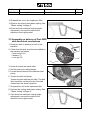
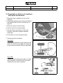
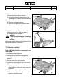
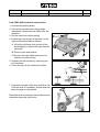
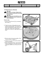
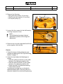
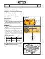
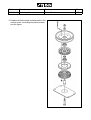
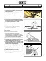
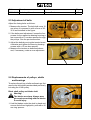
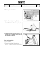
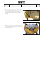
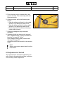
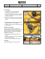
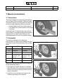
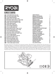
Edition
Manual
2005-06-03 Workshop Manual, Stiga Park
Chapter
1 General instructions
Page
1
Workshop
manual
Cutting decks
2WD-4WD
2000-2008
Edition
Manual
2008-05-19 Workshop Manual
Product
Mower Decks
Page
1
Mower Deck
Contents in this chapter
1.1 General 2
1.1.1 General tightening torque........... 2
1.2 Cutting theory ................................ 3
1.2.1 Cutting height ............................. 3
1.2.2 Incline ......................................... 3
1.3 Original blades............................... 4
1.3.1 Why it is so important to use original blades and blade tips from the
retail dealer? ............................... 4
1.4 Mower deck 85, 95, 105 Combi ..... 5
1.4.1 Assembly on del. of Park 4WD with
fixed deck conn. and Villa/Ready 5
1.4.2 Assembly on delivery of Park 2WD
with fixed deck connections ........ 7
1.4.3 Assembly on delivery of machines
with quick connections ................ 8
1.4.4 Basic setting ............................... 9
1.4.5 Washing position ........................ 9
1.4.6 Service position ........................ 10
1.4.7 Safety ....................................... 14
1.4.8 Replacement of blades............. 15
1.4.9 Repl. of belt, Villa/Ready-deck . 17
1.4.10 Repl. of belt, Park-deck .......... 20
1.4.11 Rep. of center pulley bearings 22
6. Mover Deck
1.5 Multiclip 107 M and 92 M ............. 24
1.5.1 Assembly on delivery................ 24
1.5.2 Raising the deck ....................... 26
1.5.3 Replacement of blades ............. 27
1.5.4 Repl. of belt, 92 M/107 M.......... 27
1.5.5 Adj. the timing belt, 92 M/107 M28
1.5.6 Replacement of belt, 107 M+.... 29
1.5.7 Adj. the timing belt, 107 M+ ...... 29
1.5.8 Replacements of pulleys, shafts
and bearings ............................. 30
1.6 Mower Deck 121 37
1.6.1 Assembly on delivery................ 37
1.6.2 Raising the deck ....................... 39
1.6.3 Replacement of blades ............. 40
1.6.4 Replacement of belts ................ 40
1.6.5 Adjustment of belts ................... 43
1.6.6 Replacements of pulleys, shafts
and bearings ............................. 43
1.7 Mower deck 110/125 Combi Pro . 47
1.7.1 Assembly on delivery................ 47
1.7.2 Raising the deck ....................... 49
1.7.3 Replacement of blades ............. 51
1.7.4 Replacement of belt.................. 51
1.7.5 Adjustment of the belt ............... 53
1.7.6 Replacements of pulleys, shafts
and bearings ............................. 54
1.7.7 Linkage ..................................... 56
1.8 Quick connections....................... 57
1.8.1 Description................................ 57
1.8.2 Assembly .................................. 57
1.8.3 Using the quick connections ..... 58
Edition
Manual
2008-05-19 Workshop Manual
Product
Mower Decks
Page
2
1 General
The decks are equipped with two or three synchronised rotating blades. The tracks of
adjacent blades are overlapping each other, which means that the synchronization is vital.
All shafts/pulleys are pivoted in sealed and permanent lubricated ball bearings.
All decks are provided with a quick-coupling to simplify the lifting up procedure for cleaning
and inspection and. The decks are also provided with an electrical or manual adjusting
device for the cutting height.
All decks are tested prior to delivery and are delivered as completely assembled as
possible. This ensures that assembly on delivery is rapid and simple.
This chapter describes assembly on delivery, repair, replacements and adjustments of
stressed parts of the mower decks.
1.1 General tightening torque
Unless otherwise stated, the following tightening torque are applicable for screws and nuts
on the machine:
Tightening torques:
Thread
Torque
M5
5 Nm
M6
9 Nm
M8
22 Nm
M10
45 Nm
Note!
Blade shafts with external threads, cutted at the shaf, have special tightening torques.
Note the actual torque in the special case.
Edition
Manual
2008-05-19 Workshop Manual
Product
Mower Decks
Page
3
1 Cutting theory
1.1 Cutting height
The best cutting results are achieved when the
when the top third of the grass is cut off.
I.e. 2/3 of the length of the grass remains.
If the grass is long and has to be cut
significantly, cut twice using different cutting
heights.
Do not use the lowest cutting heights if the lawn
surface is uneven. This would entail a risk of the
blades being damaged against the surface and
the lawn’s top layer of soil being removed.
1.2 Incline
The cutting deck’s rear section can be lifted so
that the deck has a greater forward incline than
that provided by the basic setting. This incline
affects the cutting results as follows.
No incline
When the deck is in the basic setting, the best
mulching effect and good dispersion of the cut
grass are achieved. The basic setting is
recommended for normal grass.
Incline
When the cutting deck is inclined forwards, the
mulching effect is reduced while the cut grass is
dispersed better.
Inclining forwards is recommended for thicker
grass.
1/3
Edition
Manual
2008-05-19 Workshop Manual
Product
Mower Decks
Page
4
2 Original blades
2.1
Why it is so important to use original blades and blade tips from the
retail dealer?
The table below shows the demands on original blades and blade tips, delivered from the
retail dealer.
The table is intended to display the importance to use theoriginal blades and blade tips.
Demand
Remarks
No splitting of blade tips.
Using steel balls, the manufacturer simulates what can
happen if you drive over foreign objects on the lawn. The
sharpening of the blades may be destroyed, but no parts are
allowed to loosen or fly away.
.
No splitting of blades.
.
The impact test is the toughes durability test a lawn mower can
be subject to. An iron pipe is placed right into the blades during
operation.
The blade can be deformed but it may not under any
circumstances, come off or split.
This test verifies that blades and other parts fulfil the high
safety requirements.
Optimal balance.
Minimum of noise.
Minimum of vibrations.
.
Blades and blade tips from the retail dealer have exactly the
same weight.
Blades and blade tips from the retail dealer are optimal
balanced.
This guarantee a minimum of vibration and noise which gives
a maximal durability of the machine.
It also guarantee that the machine corresponds to the
specification according to noise and vibrations.
Optimal cutting result.
Blades and blade tips from the retail dealer are optimized in
the application. I.e. the blades are adapted to the shape och
the cover and the number of revolutions to give the best cutting
result.
Edition
Manual
2008-05-19 Workshop Manual
3
Product
Mower Decks
Page
5
Mower deck
85, 95, 105 Combi
3.1 Assembly on delivery of Park 4WD
with fixed deck connections and
Villa/Ready
1. Place the deck in position in front of the
machine.
2. Check that the deck mounts are installed on
the machine as follows.
• Washer (D). Only machines up to and
including 2006.
• Deck mount (C).
• Washer (B).
• Circlip (A).
A
B
3. Screw the arms into each other.
4. Remove the belt cover (H) by loosening the
screws (I).
H
I
C
(D)
Edition
Manual
2008-05-19 Workshop Manual
Product
Mower Decks
5. Loosen the belt guide screws (K) a couple of
turns.
Page
6
Villa, Ready
K
K
Park 4WD
6. Set the maximum cutting height.
K
7. Work off the belt from the cutting deck pulley.
8. Fit the belt to the machine pulley and after
that to the cutting deck pulley.
9. Tighten the belt guide screws (K).
10.Tension the belt as follows.
Park 4WD:
Park 4WD
Grip the belt tensioner’s lever with your left
hand. Pull the lever and apply the tensioner
to the outside of the belt with your right hand.
Villa, Ready:
Tension the belt with the belt idler. The belt
idler should be on the inside of the belt and
pull out to the left (viewed from the driver’s
position).
11.Install the belt cover (H) with the screws (I).
Villa / Ready
Edition
Manual
2008-05-19 Workshop Manual
Product
Mower Decks
Page
7
12.Suspend the unit in the implement lifter.
13.Perform the cutting deck basic setting. See
“"Basic setting" at page 9”.
14.If the deck has electrical cutting height
adjustment, connect the cable to the
machine’s front right socket.
3.2 Assembly on delivery of Park 2WD
with fixed deck connections
Park 2WD
1. Place the deck in position in front of the
machine.
2. Check that the deck mounts are installed on
the machine as follows.
• Deck mount (G).
• Washer :F).
• Lock pin (E).
E
F
G
3. Screw the arms into each other.
4. Set the maximum cutting height.
5. Locate the belt around the machine’s belt
pulley.
6. Tension the belt as follows.
Tension the belt with the belt idler. The belt
idler should be on the left side of the belt
viewed from the driver’s position.
7. Suspend the unit in the implement lifter.
8. Perform the cutting deck basic setting. See
“"Basic setting" at page 9”.
9. If the deck has electrical cutting height
adjustment, connect the cable to the
machine’s front right socket.
Edition
Manual
2008-05-19 Workshop Manual
Product
Mower Decks
Page
8
3.3 Assembly on delivery of machines
with quick connections
1. Place the deck in position in front of the
machine.
2. Check that the quick connections are fitted to
the machine See "Quick connections" at
page 57.
3. Screw the arms into each other.
4. Set the maximum cutting height.
5. Set the quick connections in their rear
positions. See their supplied separate
instruction.
6. Fit the belt on to the machine pulley.
E
F
7. Tension the belt as follows.
Park 4WD:
Park 4WD
Grip the belt tensioner’s lever with your left
hand. Pull the lever and apply the tensioner
to the outside of the belt with your right hand.
Park 2WD:
Tension the belt with the belt idler. The belt
idler should be on the left side of the belt
viewed from the driver’s position.
Park 2WD
Edition
Manual
2008-05-19 Workshop Manual
Product
Mower Decks
Page
9
8. Set the quick connections in their front
positions and fit the locking pins (C).
C
9. Suspend the unit in the implement lifter.
10.Perform the cutting deck basic setting. See
"Basic setting" at page 9”.
11.If the deck has electrical cutting height
adjustment, connect the cable to the
machine’s front right socket.
3.4 Basic setting
In order for the cutting deck to cut optimally, the
correct basic setting is required. The deck is in
the basic setting when its rear edge is 5 mm
above its front edge. This means that the deck
is inclined forwards.
17”
Move the deck to the basic setting by lifting and
securing as follows.
On machines with 17” wheels: Install the
washers and the pins in the top hole.
On machines with 16” wheels: Install the
washers and the pins in the middle hole.
3.5 Washing position
1. Activate the parking brake.
2. Set the implement lifter in transport position.
3. Set the highest cutting height.
16”
Edition
Manual
2008-05-19 Workshop Manual
Product
Mower Decks
4. Detach the rear section of the deck on the
right and left-hand side as follows:
A. Lift up the left-hand rear section of the
deck slightly to reduce the load from the
cotter pin.
Page
10
C
B. Remove pins and washers.
C. Remove the right-hand cotter pin and
washer in the same way.
B
A
B
A
5. Grip the front edge of the deck and lift up.
Hook on the chain so that the deck is
pointing diagonally upwards.
Warning!
It is absolutely forbidden to start the
engine when the deck is in the washing
position.
Reset the deck according to the actual previous
described assembly instruction.
3.6 Service position
Park 4WD with fixed deck connections and
Villa/Ready
1. Activate the parking brake.
2. If the deck has electrical cutting height
adjustment, disconnect the cable from the
machine.
3. Set the maximum cutting height.
C
4. Detach the rear section of the deck on the
right and left-hand side as follows:
A. Lift up the left-hand rear section of the
deck slightly to reduce the load from the
cotter pin.
B. Remove pins and washers.
C.Remove the right-hand cotter pin and
washer in the same way.
Edition
Manual
2008-05-19 Workshop Manual
Product
Mower Decks
5. Remove the belt cover (H) by loosening the
screws (I).
Page
11
H
6. Loosen the belt guide screws (K) a couple of
turns.
I
7. Release the belt tension as follows.
Park 4WD
Park 4WD:
Grip the belt tensioner’s lever with your left
hand. Pull the lever and remove the
tensioner with your right hand.
Villa, Ready:
Remove the tensioner from the belt.
8. Force the belt off the deck’s pulley.
9. Grip the front edge of the deck and lift up. Lift
until the deck is completely vertical and rest
the rear edge on the ground.
Reset the deck according to the actual previous
described assembly instruction.
Villa / Ready
Edition
Manual
2008-05-19 Workshop Manual
Product
Mower Decks
Page
12
Park 2WD with fixed deck connections
1. Activate the parking brake.
2. If the deck has electrical cutting height
adjustment, disconnect the cable from the
machine.
3. Set the maximum cutting height.
C
4. Detach the rear section of the deck on the
right and left-hand side as follows:
A. Lift up the left-hand rear section of the
deck slightly to reduce the load from the
cotter pin.
B. Remove pins and washer.
C.Remove the right-hand cotter pin and
washer in the same way.
5. Release the belt tension by removing the
belt tensioner.
6. Force the belt off the machines’s pulley.
7. Grip the front edge of the deck and lift up. Lift
until the deck is completely vertical and rest
the rear edge on the ground.
Reset the deck according to the actual previous
described assembly instruction.
B
Park 2WD
A
Edition
Manual
2008-05-19 Workshop Manual
Product
Mower Decks
Page
13
Machines with quick connections
1. Activate the parking brake.
2. If the deck has electrical cutting height
adjustment, disconnect the cable from the
machine.
3. Set the maximum cutting height.
C
4. Detach the rear section of the deck on the
right and left-hand side as follows:
A. Lift up the left-hand rear section of the
deck slightly to reduce the load from the
cotter pin.
B. Remove pins and washer.
C.Remove the right-hand cotter pin and
washer in the same way.
A
B
5. Set the quick connections in their rear
positions.
6. Release the belt tension as follows.
Park 4WD:
Grip the belt tensioner’s lever with your left
hand. Pull the lever and remove the
tensioner with your right hand.
Park 4WD
Edition
Manual
2008-05-19 Workshop Manual
Product
Mower Decks
Park 2WD:
Remove the tensioner from the belt.
7. Force the belt off the deck’s pulley.
8. Grip the front edge of the deck and lift up. Lift
until the deck is completely vertical and rest
the rear edge on the ground.
Reset the deck according to the actual previous
described assembly instruction.
3.7 Safety
To reduce the risk of accidental injury in the
event of a collision and to protect important
parts in the cutting deck, a force limiter is
integrated as follows.
• Shear bolts between blades and blade bar.
• Torque limiting between gear wheels and
blade shaft.
• Possibility of positive drive belt slipping on
the plastic gear wheels.
Page
14
Park 2WD
Edition
Manual
2008-05-19 Workshop Manual
Product
Mower Decks
3.8 Replacement of blades
Warning!
The blades are sharp. Always wear
gloves when working with the blades
to avoid injury.
Warning!
When replacing, both blades on the
same blade bar must be replaced to
avoid imbalance.
H
Disassembly
1. Remove the belt cover (H) by unscrewing
the screws (I).
I
2. Check the torque limiting between gear
wheels and blade shaft. The arrows in the
figure must be opposite each other for an
intact deck. When torque limiting has
deployed, the arrows are not opposite each
other.
1. Rise the deck to its service position. See
“Service position” at page 10.
2. Release the screws that hold the blades, and
remove the blades.
3. After removing the blades, check whether the
shafts are damaged. This is best done by
rotating the shafts to see if they are out of
true.
Page
15
Edition
Manual
2008-05-19 Workshop Manual
Product
Mower Decks
Page
16
Assembly
1. Fit the blades according to the figure.
The sharpened surfaces of the blades shall
face in the rotation direction which is left
when the deck is raised.
Note the following when reassembling:
• The blades and blade bar must be installed
as in the figure.
• The blades can be turned 1/3 of a turn in
their mountings. Select positions so that
the blades are offset 90° from each other.
See "Synchronising, blades" at page 17.
R
Q
Tightening torque:
Screws (P) - 45 Nm
Shear bolts (Q) - 9.8 Nm
In the event of a collision, the shear bolts (Q)
can break and the blades bend back. If this has
happened, install genuine shear bolts and
tighten as above.
2. Tighten all screws.
P
Q
45 Nm
P
Edition
Manual
2008-05-19 Workshop Manual
Product
Mower Decks
Synchronising, blades
The deck has synchronised blades.
If one of the blades has struck a solid object
(e.g. a stone), the synchronisation may be
altered. This entails a risk of the blades
colliding with each other.
Correctly synchronised blades must be offset
90° from each other. See the figure.
Always check synchronisation after a collision.
If the blades are not synchronised, one or more
of the following faults may have occurred in the
cutting deck:
• The positive drive belt has slipped on the
gear wheels.
• Torque limiting between gear wheels and
blade shaft has deployed. The arrows in
the figure must be opposite each other for
an intact deck. When torque limiting has
deployed, the arrows are not opposite
each other.
• The blade member is incorrectly installed
on the blade shaft. Can be installed in
three different positions. See the previous
page.
3.9 Replacement of belt,
Villa/Ready-deck
Disassembly
1. Remove the belt cover (H) by unscrewing
the screws (I). Use a 12 mm box spanner.
H
I
Page
17
Edition
Manual
2008-05-19 Workshop Manual
Product
Mower Decks
2. Remove the following:
• Belt guide with screws (13 mm key)
• Shaft screw with washer (19 mm key)
• Pull up the pulley (A).
3. Loosen the four screws for the left bearing
housing a couple of turns.
Note!
The left bearing housing is lateral
adjustable to perform the timing belt
adjustment.
4. Remove the key at the right shaft and lift the
pulley together with the belt.
Checks
1. Check the torque limiting between gear
wheels and blade shaft. See "Synchronising,
blades" at page 17.
2. Check the two blade shaft bearings as
follows:
• Grab the pulley and force it in the radial
direction. No radial play shall be felt.
• Grab the knife and force it in the radial
direction. No radial play shall be felt.
• Rotate the shaft. No abnormal bearing
noise shall be heard.
The bearing housings are not divided in
additional spare parts. If bearing failure is
detected, replace the entire bearing housing.
Page
18
A
Edition
Manual
2008-05-19 Workshop Manual
Product
Mower Decks
Page
19
Assembly of belt, Villa/Ready-deck
Assemble the timing belt in the reverse order.
Correctly synchronised blades must be offset
90° from each other. See "Synchronising,
blades" at page 17.
Before the the left bearing housing screws are
tightened, the belt shall be adjusted.
Alternative A
Adjust as follows:
Alternative A
300 N
1. Stretch the belt by pulling the the left bearing
housing with a force of 300 N (30 kg).
2. Tighten the four bearing housing screws.
Alternative B
1. Stretch the belt by pulling the the left bearing
housing.
Alternative B
10 mm
2. Tighten the four bearing housing screws.
3. Apply a force as per the table below in the
middle of the belt. The belt shall move 10
mm. If not, loosen the bearing housing and
repeat step 1-2 above until the movement is
OK.
Timing belt adjustments:
Deck
85 Combi
95 Combi
Force
45 N
35 N
Movement
10 mm
10 mm
When assembling the belt cover (H) use the
two M8-screws with 12 mm head.
35/45 N
H
The cover recesses have no place for a 13 mm
spanner.
12 mm head
Edition
Manual
2008-05-19 Workshop Manual
Product
Mower Decks
3.10 Replacement of belt,
Park-deck
H
Disassembly
1. Remove the belt cover (H) by unscrewing
the screws (I). Use a 12 mm box spanner.
I
2. Remove the belt guide with screws (13 mm
spanner).
3. Loosen the left and right bearing housing
screws a couple of turns (8 screws).
Note!
The bearing housings are lateral
adjustable to perform the timing belt
adjustments.
4. Work off the belts from the pulleys.
Checks
1. Check the torque limiting between gear
wheels and blade shaft. See "Synchronising,
blades" at page 17.
2. Check the two blade shaft bearings as
follows:
• Grab the pulley and force it in the radial
direction. No radial play shall be felt.
• Grab the knife and force it in the radial
direction. No radial play shall be felt.
• Rotate the shaft. No abnormal bearing
noise shall be heard.
Page
20
Edition
Manual
2008-05-19 Workshop Manual
Product
Mower Decks
Page
21
The bearing housings are not divided in
additional spare parts. If bearing failure is
detected, replace the entire bearing housing.
3. Check the center pulley bearings as follows:
• Grab the pulley and force it in the radial
direction. No radial play shall be felt.
• Rotate the pulley. No abnormal bearing
noise shall be heard.
To replace bearings, see "Replacements of
center pulley bearings" at page 22.
Assembly of belt, Park-deck
Assemble the timing belts in the reverse order.
Before the the left and right bearing housing
screws are tightened, the belts shall be
adjusted.
Adjust as follows:
Alternative A
Alternative A
1. Stretch the belt by pulling the the bearing
housings with a force of 300 N (30 kg).
300 N
2. Tighten the bearing housing screws.
Alternative B
1. Stretch the belt by pulling the the left bearing
housing.
Alternative B
10 mm
2. Tighten the four bearing housing screws.
3. Apply a force as per the table below in the
middle of the belt. The belt shall move 10
mm. If not, loosen the bearing housing and
repeat step 1-2 above until the movement is
OK.
Timing belt adjustments:
Deck
95 Combi
105 Combi
Force
80 N
70 N
Movement
10 mm
10 mm
80/70 N
Edition
Manual
2008-05-19 Workshop Manual
Product
Mower Decks
H
When assembling the belt cover (H) use the
two M8-screws with 12 mm head.
The cover recesses have no place for a 13 mm
spanner.
12 mm head
3.11 Replacements of center pulley
bearings
To replace the center pulley bearings, first
remove the timing belts. See "Replacement of
belt, Park-deck" at page 20.
Proceed as follows:
1. .Remove the pulley plate by unscrewing the
two screws.
2. Set up the unit in a vise and disassemble it.
Use two 17 mm spanners.
Page
22
Edition
Manual
2008-05-19 Workshop Manual
Product
Mower Decks
Page
23
3. Replace defective parts and assemble in the
reverse order. According the parts location,
see the figure.
24 Nm
Edition
Manual
2008-05-19 Workshop Manual
Product
Mower Decks
4 Multiclip 107 M and 92 M
4.1 Assembly on delivery
1. Take the deck out of the box.
2. Fit the deck arms in the front deck
atachments.
4. Set the cutting height just above the
middleheight. In this position, the deck arms
are not blocked by the side supports at the
deck. Since the deck is moving up and down
in a cirkular movement it will be closest to the
PTO pulley which facilitate the belt
attachment.
5. Attach the deck arms to the front wheel
shafts of the machine and secure with the
locking pins.
Note!
One flat washer shall be placed at each
side of the deck arms onto the wheel
shafts.
6. Lift up the deck at the rear at the left and right
side until the deck engages in the quick
release locks.
7. Attach the front spring hinge to the machine
front elevating arm.
Page
24
Edition
Manual
2008-05-19 Workshop Manual
Product
Mower Decks
Page
25
8. Fit the V-belt to the articulation point pulley
and tension the belt by hooking up the lever
or the spring, depending on model.
9. If applicable, fit the electrical height
adjustment connector to the machine.
Basic setting
Perform basic setting as follows:
1. Place the machine on a level floor.
Requirements for floor flatness: ±1 mm/m.
No slope towards a floor drain or similar may
occur in front of or behind the machine.
2. The tyres must have the correct air pressure.
5 mm
3. Place the deck in transport position and lay
a plane-parallel plank under the deck.
4. Place a 5 mm tall spacer on the plank under
the rear edge of the cutting deck, and lower
the deck to the working position.
5. Undo the screws (K) so that the deck rests
against the plank and the spacer. Check that
the deck does not lean sideways in relation
to the machine.
J
6. Tighten the screws (K) to 22 Nm.
7. Place the deck in transport position and
remove the plank.
K
L
Edition
Manual
2008-05-19 Workshop Manual
Product
Mower Decks
Page
26
4.2 Raising the deck
After every cutting, the deck shall be raised for
cleaning and inspection. The raising procedure
is performed in five steps. The lowering is
performed in the same five steps, but with step
2-4 in the opposite order. The steps order at
raising are as follows:
1. Set the cutting height just above the
middleheight. Since the deck is moving up
and down in a cirkular movement it will be
closest to the PTO pulley which facilitate the
belt attachment.
2. Lift the deck at the rear and release the quick
release lock at the right side.
See A + B + C.
3. Lift the deck at the rear and release the quick
release lock at the left side.
See above.
Note!
If the deck is equipped with electric height
adjustment, disconnect the connector
from the machine.
4. Slacken the belt by hooking off the lever or
the spring, depending on model and remove
the V-belt from the articulation point pulley.
5. Raise the deck and let it rest on the rear.
As mentioned above, the lowering is performed
in the opposite order. That means the steps
above in the following order:
1-5-4-3-2
A
B
C
Edition
Manual
2008-05-19 Workshop Manual
Product
Mower Decks
Page
27
4.3 Replacement of blades
Warning!
The blades are sharp. Always wear
gloves when working with the blades
to avoid injury.
1. Release the screws that hold the blades, and
remove the blades.
After removing the blades, check whether the
shafts are damaged. This is best done by
rotating the shafts to see if they are out of
true.
2. Fit the blades with the raised edge towards
the blade attachment.
The sharpened surfaces of the blades shall
face in the rotation direction, which is left for
92 M, when the deck is raised.
Note!
The blades shall be tightened to
24 Nm.
107 M exist in two versions:
• Both blades rotate in the same direction,
, whichs is left.
• The blades rotate against each other.
This deck is denominated 107 M+
3. Tighten the screws to the correct torque.
4.4 Replacement of belt, 92 M/107 M
This procedure is valid for 107 M
, where
the blades rotate in the same direction and for
92 M.
To replace the timing belt, follow the steps
below:
1. Remove the deck cover by loosening the two
nuts and the screw.
A
2. Loosen, but don´t remove the two screws (A
and B), holding the timing belt adjustment
arm. See the figure.
3. Remove the V-belt support (C) and the Vbelt.
4. Back off the timing belt and assemble the
new one.
B
C
Edition
Manual
2008-05-19 Workshop Manual
Product
Mower Decks
Page
28
5. Reassemble the V-belt and its support (C).
C
C
Warning!
The tracks of adjacent blades are overlapping each other, which means that
the synchronization is vital. Failed synchronization will result in severe damage to the blades and to the deck.
6. When the timing belt is engaged with the
pulleys, the blades shall be displaced
exactly 90° in relation to each other. See the
figure.
7. Adjust the timing belt tension as described
below and refit the deck cover.
4.5 Adjusting the timing belt,
92 M/107 M
This procedure is valid for 107 M
, where
the blades rotate in the same direction and for
92 M.
10 mm
Adjust the timing belt as follows:
1. Measure the tension. The belt shall move 10
mm when it is pressed in with a force of
30-35 N as illustrated in the figure.
2. If the timing belt needs adjusting, loosen the
two nuts (A and B) in the figure.
30-35 N
A
3 Move the adjustment arm by help of a 17 mm
spanner and tighten the nuts, first nut B and
then nut A.
Note!
Both nuts must be tightened when the
measurement is performed.
4. Measure the tension as described above
and, if necessary, make a new adjustment.
B
Edition
Manual
2008-05-19 Workshop Manual
Product
Mower Decks
Page
29
4.6 Replacement of belt, 107 M+
This procedure is valid for 107 M+
the blades rotate against each other.
, where
To replace the timing belt, follow the steps
below:
1. Remove the deck cover by loosening the two
nuts and the screw.
2. Loosen, but don´t remove the three screws
(C), holding the timing belt adjustment arm.
See the figure.
3. Remove the V-belt support (A) and the Vbelt.
4. Slacken the timing belt by removing the
nut (B).
4. Back off the timing belt and assemble the
new one.
5. Reassemble the V-belt and its support (A).
Warning!
The tracks of adjacent blades are overlapping each other, which means that
the synchronization is vital. Failed synchronization will result in severe damage to the blades and to the deck.
6. When the timing belt is engaged with the
pulleys, the blades shall be displaced
exactly 90° in relation to each other. See the
figure.
7. Adjust the timing belt tension as described
below and refit the deck cover.
4.7 Adjusting the timing belt, 107 M+
This procedure is valid for 107 M+
the blades rotate against each other.
Adjust the timing belt as follows:
, where
A
B
C
Edition
Manual
2008-05-19 Workshop Manual
Product
Mower Decks
Page
30
1. Measure the tension. The belt shall move 12
mm when it is pressed in with a force of
30-35 N as illustrated in the figure.
B
C
2. If the timing belt needs adjusting, loosen the
three nuts (C) ca one turn in the figure.
3 Loosen the counternut to nut (B) (to the right
of nut B) and adjust the tension with nut (B).
4. Tighten the counternut to nut (B) and the
three nuts (C).
12 mm
Note!
All nuts must be tightened when the final
measurement is performed.
30-35 N
4. Measure the tension as described above
and, if necessary, make a new adjustment.
4.8 Replacements of pulleys, shafts
and bearings
The mower deck 107 M
, where the
blades rotate in the same direction 92 M are
equipped with three different types of pulleys,
namely:
• A, Blade shaft pulleys, 2 pcs.
• B, Adjustment pulley.
• C, Intermediate pulley which is two assembled pulleys, one for the timing belt and one
for the V-belt.
The mower deck 107 M
, where the
blades rotate against each other is equipped
with three different types of pulleys, namely:
• A, Blade shaft pulleys, 2 pcs.
• C, Intermediate pulley which is two assem-
A
B
C
A
D
A
C
A
D
Edition
Manual
2008-05-19 Workshop Manual
Product
Mower Decks
bled pulleys, one for the timing belt and one
for the V-belt.
• B, Adjustment pulleys, 2 pcs.
To replace the pulleys, shafts and bearings, first
remove the timing belt as described previously.
17/19 mm
Blade shaft pulley (A) and blade shaft
Warning!
The blades are sharp. Always wear
gloves when working with the blades
to avoid injury.
1. Hold the blade under the deck by hand and
remove the nut with a 17/19 mm spanner.
2. Normally, the pulleys can be forced from the
shaft by hand, however, if it is tight on the
shaft, a puller can be used. See the figure.
3. Remove the key (A) and washer (B) under
the pulley.
The washer (B) is introduced during pending
production to prevent axial play, i.e. all decks
are not provided with the washer.
4. Pull out the blade shaft downwards.
5. Replace defective parts and assemble in
reverse order.
Older decks, without washer (B) shall be
provided with the washer. See the spare
parts catalogue.
Page
31
Edition
Manual
2008-05-19 Workshop Manual
Product
Mower Decks
Page
32
Note!
The the location of the distance (C),
washer (B) and key (A) on the blade shaft.
Warning!
A
B
The threads will be destroyed if the
nuts are tightened above the torques
defined below.
5. Tighten the shaft nut as follows:
M10 to 40 Nm
M12 to 50 Nm
6. Refit and adjust the timing belt as described
previously.
C
Blade shaft bearings
Each blade shaft is equipped with two sealed
and permanent lubricated ball bearings. To
replace the blade shaft bearings, first remove
the timing belt their pulleys and the blade shafts
as described previously.
Than proceed as follows:
1. Remove the transmission plate by
unscrewing the 9 M8-screws and the Phillips
screw (B). Each M8-screw has a nut on the
opposite side under the deck, except the
screw (A). Use two 13 mm wrenches.
2. Remove the transmission plate and the
bearing housings.
3. In normal cases the complete bearing
housing shall be replaced, in this case
proceed with step 9. The bearing housing is
not divided in the spare parts list. However,
the bearings can be replaced as described
below.
4. Set up the bearing housing in a vice and
move the distance between the bearings off
centre.
A
B
Edition
Manual
2008-05-19 Workshop Manual
Product
Mower Decks
Page
33
Warning!
To avoid burns, use gloves when
handling heat parts.
5. Heat the bearing housing to about 100°C
and knock carefully out the lower bearing
with help of a round bar and a hammer..
6. Turn the bearing housing and knock out the
other bearing.
7. Refit new bearings and the distance when
the bearing housing is still warm.
8. Assemble the bearing housings and
transmission plate in the reverse order.
Note!
Check that the dowel pins (C) at the
bearing housings fit in the holes in the
deck housing. See the figure.
Note!
Check that the cup washes (D) is in place.
See the figure.
9. Assemble the pulleys. Refit and adjust the
timing belt as described previously.
C
D
Edition
Manual
2008-05-19 Workshop Manual
Product
Mower Decks
Page
34
Adjustment pulley (B), 92 M/107 M
This procedure is valid for 107 M
, where
the blades rotate in the same direction and for
92 M.
To dismantle the adjustment pulley (B), first
remove the timing belt as described previously.
17 mm
Then proceed as follows:
1. Hold the nut under the unit and remove the
screw at the top of the unit. Use two 17 mm
spanners.
The bearing and pulley are permanently
assembled and shall be replaced as one unit.
2. Assemble the new pulley in reverse order.
Note!
Note the location of the distance (A) and
washer (B).
B
3. Refit and adjust the timing belt as described
previously.
A
Edition
Manual
2008-05-19 Workshop Manual
Product
Mower Decks
Page
35
Adjustment pulley (D), 107 M+
This procedure is valid for 107 M+
the blades rotate against each other.
, where
C
B
To dismantle the adjustment pulleys (D), first
remove the timing belt as described previously.
Then proceed as follows:
1. Remove the nuts (B and C), take care of the
screws and washers from the under side.
2. Take out the entire adjustment plate with the
two pulleys and remove the pulleys. Use two
17 mm spanners.
3. Disassemble the pulleys by removing the
four M6 screws with nuts.
4. Check the bearings by rotating them. No
abnormal noise shall be heard.
5. Assemble the pulleys in reverse order.
6. Refit and adjust the timing belt as described
previously.
D
Edition
Manual
2008-05-19 Workshop Manual
Product
Mower Decks
Page
36
Intermediate pulleys with bearings
To dismantle the intermediate pulleys with
bearings, first remove the timing belt as
described previously.
Then proceed as follows:
1. Use a 17 mm spanner and remove the screw
(A) and the pulleys.
Note!
The nut is fixed under the plate and must
not be held.
A
2. Dismantle the unit by unscrewing the four
M6-screws.
B
3. Press out the bearing from the V-belt
pulley (B).
C
4. Replace defective parts and assemble the
unit in reverse order and according to the
figure.
D
B. V-belt pulley
E
C. Bearing
C
D. Distance
E. Pulley halves
E
F. Fixation sleeve
5. Reassemble the pulleys to the mower deck.
Note the washers (G) above the unit.
F
3. Refit and adjust the timing belt as described
previously.
G
Edition
Manual
2008-05-19 Workshop Manual
Product
Mower Decks
5 Mower Deck 121
5.1 Assembly on delivery
This instruction describes assembly with fixed
deck connections. If quick connections shall be
used, see "Quick connections" at page 57.
1. Take the deck out of the box.
2. Fit the deck short deck arms onto the front
wheel shafts of the machine and secure with
the locking pins.
Note!
One flat washer shall be placed at each
side of the deck arms onto the wheel
shafts.
4. Set the cutting height just above the
middleheight. In this position, the deck arms
are not blocked by the side supports at the
deck. Since the deck is moving up and down
in a cirkular movement it will be closest to the
PTO pulley which facilitate the belt
attachment.
5. Remove the two height locking pins.
6. Secure the short deck arms to the deck with
the two M10-screws.
Page
37
Edition
Manual
2008-05-19 Workshop Manual
Product
Mower Decks
Page
38
7. Heighten the deck at the rear and refit the
height locking pins.
8. Attach the front spring hinge to the machine
front elevating arm.
9. Fit the V-belt to the articulation point pulley
and tension the belt by hooking up the lever
or the spring, depending on model.
10.Fit the electrical height adjustment
connector to the machine.
Basic setting
Perform basic setting as follows:
1. Place the machine on a level floor.
Requirements for floor flatness: ±1 mm/m.
No slope towards a floor drain or similar may
occur in front of or behind the machine.
2. The tyres must have the correct air pressure.
3. Place the deck in transport position and lay
a plane-parallel plank under the deck.
5 mm
4. Place a 5 mm tall spacer on the plank under
the rear edge of the cutting deck, and lower
the deck to the working position.
5. Undo the screws (H) so that the deck rests
against the plank and the spacer. Check that
the deck does not lean sideways in relation
to the machine.
6. Tighten the screws (H) to 22 Nm.
7. Place the deck in transport position and
remove the plank.
H
Edition
Manual
2008-05-19 Workshop Manual
Product
Mower Decks
5.2 Raising the deck
After every cutting, the deck shall be raised for
cleaning and inspection. The raising procedure
is performed in five steps. The lowering is
performed in the same five steps, but with step
2-4 in the opposite order. The steps order at
raising are as follows:
1. Set the cutting height just above the
middleheight. Since the deck is moving up
and down in a cirkular movement it will be
closest to the PTO pulley which facilitate the
belt attachment
2. Lift the deck at the rear and release the
locking pin at the right side.
3. Lift the deck at the rear and release the
locking pin at the left side.
Note!
Disconnect the connector for the electric
height adjustment from the machine.
4. Slacken the belt by hooking off the lever or
the spring, depending on model and remove
the V-belt from the articulation point pulley.
5. Raise the deck and let it rest on the rear.
As mentioned above, the lowering is performed
in the opposite order. That means the steps
above in the following order:
1-5-4-3-2
Page
39
Edition
Manual
2008-05-19 Workshop Manual
Product
Mower Decks
5.3 Replacement of blades
Warning!
The blades are sharp. Always wear
gloves when working with the blades
to avoid injury.
1. Release the screws that hold the blades, and
remove the blades.
After removing the blades, check whether the
shafts are damaged. This is best done by
rotating the shafts to see if they are out of
true.
2. Fit the blades with the raised edge towards
the blade attachment.
The sharpened surfaces of the blades shall
face in the rotation direction which is left when
the deck is raised.
3. Tighten the screws to 24 Nm.
5.4 Replacement of belts
To replace the timing belts, follow the steps
below:
1. Remove the deck cover by loosening the two
screws.
2. Loosen the four screws for the left and right
bearing housings a few turns with a 13 mm
box spanner through the pulleys.
Note!
Do not loose the intermediate bearing
housing.
Page
40
Edition
Manual
2008-05-19 Workshop Manual
Product
Mower Decks
Page
41
3. Loose the tension bar screws a few turns
and slacken the belts.
Warning!
The blades are sharp. Always wear
gloves when working with the blades
to avoid injury.
4. Remove the V-belt pulley with a 16 mm ring
spanner. Hold the blade from the under side.
5. Work off the timing belts at the intermediate
pulley.
Note!
First the right belt and than the left one.
6. Check the three knife shaft bearings as
follows:
• Grab the pulley and force it in the radial
direction. No radial play shall be felt.
• Grab the knife and force it in the radial
direction. No radial play shall be felt.
• Rotate the shaft. No abnormal bearing
noise shall be heard.
If bearing faults are determined, proceed
with "Replacements of pulleys, shafts and
bearings" at page 43.
7. Fit the new belts onto the pulleys. First the
left belt and than the right one.
16 mm
Edition
Manual
2008-05-19 Workshop Manual
Product
Mower Decks
Warning!
The tracks of adjacent blades are overlapping each other, which means that
the synchronization is vital. Failed synchronization will result in severe damage to the blades and to the deck.
8. When the timing belts are engaged with the
pulleys, the blades shall be displaced
exactly 90° in relation to each other. See the
figure.
Warning!
The threads will be detstroyed if the
nut is tightened above the torque below.
9. Refit the V-belt pulley with washer and nut.
Use a 16 mm ring spanner. Hold the blade
from the under side.
Note!
Tighten the shaft nut to 50 Nm.
10.Adjust the belts as described below.
11.Refit the deck cover and secure with the two
screws and washers.
Page
42
Edition
Manual
2008-05-19 Workshop Manual
Product
Mower Decks
Page
43
5.5 Adjustment of belts
Adjust the timing belts as follows:
1. Measure the tension. The belt shall move 10
mm when it is pressed in with a force of 3035 N as illustrated in the figure.
2. If the belts need adjustment, loosen the four
screws for the respective bearing housing a
few turns with a 13 mm box spanner through
the pulleys. See the previous section.
10 mm
30-35 N
3. Adjust the belts by moving the tension levers
clockwise and tighten the bearing housing
screws with a 13 mm box spanner.
4. Measure the tension as described above
and, if necessary, make a new adjustment.
5.6 Replacements of pulleys, shafts
and bearings
To replace the pulleys, shafts and bearings, first
remove the timing belts as described previously
including the V-belt pulley.
Blade shaft pulley and blade shaft
Warning!
The blades are sharp. Always wear
gloves when working with the blades
to avoid injury.
1. Hold the blades under the deck by hand and
remove the left and right pulley nuts with a 16
mm ring spanner.
19 mm
Edition
Manual
2008-05-19 Workshop Manual
Product
Mower Decks
Page
44
2. Remove the washers, located over the
pulleys.
3. Normally, the pulleys can be forced from the
shaft by hand, however, if it is tight on the
shaft, a puller can be used. See the figure.
4. Remove the keys (A) and washers (B) under
the pulleys. Pull out the blade shaft
downwards.
A
B
5. Replace defective parts and proceed with
the assembling as follows.
Note!
The the location of the distance (C) and
the shell washer (D) on the blade shafts.
Warning!
The threads will be detstroyed if the
nuts are tightened above the torque
defined below.
6. Tighten the left and right shaft nuts to
50 Nm. The nut for the intermediate shaft
shall be mounted in connection with the belt
assembly later.
D
C
Edition
Manual
2008-05-19 Workshop Manual
Product
Mower Decks
Page
45
Note!
The shaft nuts shall be tightened to
50 Nm.
7. Assemble the pulleys with keys (A) and
washers. Since the belts are placed on
different levels, there are a different number
of washers under and above the three
pulleys. The washer locations are shown in
the figure.
Pulleys:
1. Left pulley
2. Intermediate pulley
3. Right pulley
8. If the blade shaft bearings/bearing housings
shall be replaced, see the next page.
9. Refit and adjust the timing belts as described
previously.
1
2
3
Edition
Manual
2008-05-19 Workshop Manual
Product
Mower Decks
Blade shaft bearings
Each blade shaft is equipped with two sealed
and permanent lubricated ball bearings. To
replace the blade shaft bearings, first remove
the timing belt their pulleys and the blade shafts
as described previously.
Than proceed as follows:
1. Remove the actual bearing housing by
unscrewing the four M8-screws.
2. Perform the bearing replacement as
described "Blade shaft bearings" at page 32
in position 3-7 at page 32.
Warning!
To avoid burns, use gloves when
handling heat parts.
3. Assemble the pulleys. Refit and adjust the
timing belts as described previously.
Page
46
Edition
Manual
2008-05-19 Workshop Manual
6
Product
Mower Decks
Mower deck
110 and 125 Combi Pro
6.1 Assembly on delivery
This instruction describes assembly with fixed
deck connections. If quick connections shall be
used, see "Quick connections" at page 57.
Mower deck
1. Take the deck out of the box.
2. Place the cutting deck in position in front of
the machine.
3. Install the deck mounts on the front shafts.
Note!
One flat washer shall be placed at each
side of the deck arms onto the wheel
shafts.
4. Remove the pins and the washers on both
sides.
5. Screw the arms into each other.
6. Suspend the cutting deck in the implement
lifter.
Page
47
Edition
Manual
2008-05-19 Workshop Manual
Product
Mower Decks
6. If the deck has electrical cutting height
adjustment, connect the cable to the
machine’s front right socket.
Belt
The cutting deck’s rear section should rest on
the floor (it should not be lifted or secured).
Install the belt as follows:
1. Set the maximum cutting height.
2. Locate the belt around the machine’s belt
pulley (B).
3. Fit the V-belt to the articulation point pulley
and tension the belt by hooking up the lever
or the spring, depending on model.
4. Lift up and secure the rear section of the
cutting deck.
On machines with 17” wheels: Install the
washers and the pins in the top hole.
On machines with 16” wheels: Install the
washers and the pins in the middle hole.
Page
48
Edition
Manual
2008-05-19 Workshop Manual
Product
Mower Decks
6.2 Raising the deck
The deck can be raised according to two
procedures:
• 45° for washing and cleaning.
• 90° for service.
Washing position
1. Activate the parking brake.
2. Set the implement lifter in transport position.
3. Set the lowest cutting height.
4. Remove pins and washers.
5. Grip the front edge of the deck and lift up.
Hook on the chain so that the deck is
pointing diagonally upwards.
It is absolutely forbidden to start the engine
when the deck is in the washing position.
Reset washing position
1. Lower the deck.
2.Proceed according to position 4 at page 48.
Service position
1. Activate the parking brake.
2. Set the implement lifter in transport position.
3. If the deck has electrical cutting height
adjustment, disconnect the cable from the
machine.
4. Set the highest cutting height.
Page
49
Edition
Manual
2008-05-19 Workshop Manual
Product
Mower Decks
5. Remove pins and washers.
6.Slacken the belt by hooking off the lever or
the spring, depending on model and remove
the V-belt from the articulation point pulley.
8. Grip the front edge of the deck and lift up. Lift
until the deck is completely vertical and rest
the rear edge on the floor.
Reset service position
1. Lower the deck.
2. Proceed according to "Assembly on
delivery" at page 47, position 6 and further.
Page
50
Edition
Manual
2008-05-19 Workshop Manual
Product
Mower Decks
Page
51
6.3 Replacement of blades
Warning!
The blades are sharp. Always wear
gloves when working with the blades
to avoid injury.
1. Rise the deck to its service position. See
“Service position” at page 49.
2. Release the screws that hold the blades, and
remove the blades.
After removing the blades, check whether the
shafts are damaged. This is best done by
rotating the shafts to see if they are out of
true.
24 Nm
3. Fit the blades with the raised edge towards
the blade attachment.
The sharpened surfaces of the blades shall
face in the rotation direction which is left when
the deck is raised.
3. Tighten the screws.
Note!
The blades shall be tightened to 24 Nm.
6.4 Replacement of belt
To replace the internal belt, follow the steps
below:
1. Rise the two attachment arms and let them
rest against the frame tubes.
Note!
To avoid laquer damages, place protection
plates under the arms.
2. If necessary, remove the top cover.
24 Nm
Edition
Manual
2008-05-19 Workshop Manual
Product
Mower Decks
3. Set the cutting height to max. If the deck is
provided with electrical height adjustment,
connect the cable either to a machine and
use the machine switch or to a separate
battery.
4. Remove the deck cover by loosening the two
rear screws and if necessary the belt guide
with its two screws.
Page
52
Edition
Manual
2008-05-19 Workshop Manual
Product
Mower Decks
5. Force the belt over a suitable pulley and
remove the belt. The tensioning roller will
follow automatic.
6. Check the three knife shaft bearings as
follows:
• Grab the pulley and force it in the radial
direction. No radial play shall be felt.
• Grab the knife and force it in the radial
direction. No radial play shall be felt.
• Rotate the shaft. No abnormal bearing
noise shall be heard.
7. Check the linkage for play and other
damages.
8. If bearing faults are determined, proceed
with “"Replacements of pulleys, shafts and
bearings" at page 54” below.
If the linkage needs repair, proceed with
“"Linkage" at page 56”.
Otherwise mount the new belt in the reverse
order.
Note!
Always use original spare belts from the
retail dealer.
6.5 Adjustment of the belt
The internal belt is automatic adjusted by the
roller, fitted on the spring forced lever, and does
not need any further adjustment.
Page
53
Edition
Manual
2008-05-19 Workshop Manual
Product
Mower Decks
6.6 Replacements of pulleys, shafts
and bearings
A
To replace the pulleys, shafts and bearings, first
remove the internal belt as described
previously.
B
Below is described the disassembly/assembly
of the center shaft unit. To repair the other units,
use the applicable instructions described
below.
Blade shaft pulley and blade shaft
Warning!
The blades are sharp. Always wear
gloves when working with the blades
to avoid injury.
1. Hold the blades under the deck by hand and
remove the pulley nut (A) with washer (B).
Use a 17 mm ring spanner.
2. Support the shaft unit against the floor with a
wood piece or similar and remove the
following parts:
• Upper pulley (C)
• Key (D)
• Distance sleeve (E)
• Lower pulley (F)
• Key (G)
3. Lift the deck carefully at the front and pull out
the shaft unit downwards.
If the bearings shall be replaced, proceed with
“Bearings” below. Otherwise proceed with
“Assembly”.
Blade shaft bearings
1. Remove the four screws, holding the bearing
housing. Use two 13 mm spanners.
2. Take out the bearing housing.
3. Replace the bearings as described in
position 3-7 at page 32.
Page
54
C
D
19 mm
E
F
G
Edition
Manual
2008-05-19 Workshop Manual
Product
Mower Decks
Page
55
Assembly
Note!
According the blades, see "Replacement
of blades" at page 51.
H
Assemble the shaft unit in the reverse order.
1. The bearings (H) and sleeve (I) shall be
mounted in the bearing housing.
2. Fit the bearing housing on the deck with the
four screws and washers.
I
3. Mount the washers (J and K) and sleeve (L)
on the shaft.
H
4. Push up the shaft through the bearings.
J
5. Assemble the upper parts as described at
the previous page.
K
Note!
The pulleys (F) shall be turned with the
mark (UP) faced upwards.
L
Note!
The blades shall be tightened to 24 Nm.
24 Nm
Edition
Manual
2008-05-19 Workshop Manual
Product
Mower Decks
Page
56
6.7 Linkage
1. Remove the covers as described in
"Replacement of belt" at page 51.
2. The cutting height shall remain in the upper
position. In this position, the spring has a
minimum of tension.
3. Bend a 1 mm steel wire to form a narrow
hook, fit it to the spring loop and pull off the
spring.
4. Remove the elbow links. Use a 13 spanner
and hold with a 11 mm U-spanner.
5. Replace defective parts and assemble in the
reverse order.
Adjustment of linkage
The deck linkage desires the difference
between the ground height at the rear and front
part of the deck. To achieve correct basic
setting of the deck, perform the inclination
adjustment as follows:
1. Place a plane-parallel plank under the
wheels.
2. Adjust the linkage until the deck front edge is
22 mm from the plank.
3. Refit and lock the linkage adjustments.
Assembly
Assemble all parts in the reverse order.
22 mm
Edition
Manual
2008-05-19 Workshop Manual
Product
Mower Decks
Page
57
7 Quick connections
7.1 Description
The quick-release mountings are intended for
use on Stiga’s Park machines, 2WD and 4WD.
The quick-release mountings allow the deck to
be moved easily between the two positions:
• Normal position with fully tensioned belt.
• 4 cm behind the normal position with slackened belt.
As the belt idler is released from the belt, the
quick-release mountings simplify belt and deck
replacement, and also make shifting to the
washing position and service positions easier.
7.2 Assembly
The delivery consists of the following
components. The figures only display the righthand side, but the numbers below refer to both
sides.
A
Position
B
2WD
4WD
A
2 cotter pins
2 locking rings
B
4 washers
4 washers
C
2 locking pins
2 locking pins
D
Quick-release
mounting, right
and left
Quick-release
mounting, right
and left
E
2 screws
2 screws
F
2 nuts
2 nuts
Install the quick-release mountings according
to the instructions below.
1. Only applies to 2WD machines; Lubricate
the shaft ends of the machine and the quickrelease mounting’s bearing surface with oil
before installation.
2. Install the quick-release mountings to the
machine according to the figures.
Park 2WD
B
C
D
Park 4WD
A
C
D
B
Edition
Manual
2008-05-19 Workshop Manual
Product
Mower Decks
3. Only applies to 2WD machines; Bend out the
cotter pin’s (A) leg along the periphery of the
shaft in order to secure it in the shaft.
4. Only applies to 4WD machines; Lubricate
the lubricating cup for the quick-release
mounting using a grease gun until grease
penetrates along the shaft sides.
7.3 Using the quick connections
Releasing the belt tension
1. Remove the locking pins (C) from both sides.
2. Press down the rear section of the quickrelease mountings with your heel.
3. Carry out necessary corrective action, e.g.
setting the deck to the service position.
Tensioning the belt
First tension one side and then the other
according to the instructions below.
Use protective gloves when handling
the lever. Risk of crushing injuries.
1. Firmly grasp the lever (5:G) in front of the
centre of the shaft and carefully turn 180°
forwards.
2. Install the locking pin (C).
3. Carry out the above on the other side.
C
Page
58