1
PSZ 19:16 (Pind. 1/ 97)
UNIVERSITI TEKNOLOGI MALAYSIA
BORANG PENGESAHAN STATUS TESIS♦
JUDUL : A COMMUNICATION BETWEEN EMBEDDED TCP/IP SENSOR NODES
SESI PENGAJIAN : 2006/2007
Saya _
_
RUZAINI BINTI ABD RAZAK
(HURUF BESAR)
mengaku membenarkan tesis (PSM/Sarjana/Doktor Falsafah)* ini disimpan di Perpustakaan Universiti
Teknologi Malaysia dengan syarat-syarat kegunaan seperti berikut :
1.
2.
3.
4.
Hakmilik tesis adalah di bawah nama penulis melainkan penulisan sebagai projek bersama dan
dibiayai oleh UTM, hakmiliknya adalah kepunyaan UTM.
Perpustakaan Universiti Teknologi Malaysia dibenarkan membuat salinan untuk tujuan pengajian
sahaja.
Perpustakaan dibenarkan membuat salinan tesis ini sebagai bahan pertukaran di antara institusi
pengajian tinggi.
** Sila tandakan ( √ )
SULIT
TERHAD
√
(Mengandungi maklumat yang berdarjah keselamatan atau kepentingan
Malaysia seperti yang termaktub didalam AKTA RAHSIA RASMI
1972.)
(Mengandungi maklumat TERHAD yang telah ditentukan oleh
organisasi/badan di mana penyelidikan dijalankan.)
TIDAK
TERHAD
Disahkan oleh,
(TANDATANGAN PENULIS)
(TANDATANGAN PENYELIA)
Alamat Tetap : 118 ALOR LINTAH,
22000 JERTEH,
TERENGGANU.
Nama Penyelia : PROF. DR. NORSHEILA
BINTI FISAL.
Tarikh
Tarikh
Catatan
: 22 NOVEMBER 2006
: 22 NOVEMBER 2006
* Potong yang tidak berkenaan.
** Jika tesis ini SULIT atau TERHAD, sila lampirkan surat daripada pihak berkuasa/
organisasi berkenaan dengan menyatakan sekali tempoh tesis ini perlu dikelaskan sebagai
SULIT atau TERHAD.
♦ Tesis dimaksudkan sebagai tesis bagi Ijazah Doktor Falsafah dan Sarjana secara
penyelidikan, atas disertasi bagi pengajian secara kerja kursus dan penyelidikan, atau
Laporan Projek Sarjana Muda (PSM).
“I declared that I had read this thesis and in my opinions the thesis had fulfill all of the
requirements
for
obtaining
a
Bachelor’s
Degree
in
Electrical
Engineering
(Telecommunication)”
Signature
:
___________________________
Supervisor
:
PROF. DR. NORSHEILA BINTI FISAL
Date
:
22 NOVEMBER 2006
A COMMUNICATION BETWEEN EMBEDDED TCP/IP SENSOR NODES
RUZAINI BINTI ABD RAZAK
Submitted to the Faculty of Electrical Engineering in partial fulfillment of the
requirements for the award of a degree in Bachelor of Electrical Engineering
(Telecommunication)
Faculty of Electrical Engineering
Universiti Teknologi Malaysia
NOVEMBER 2006
ii
I declare that this thesis entitled “A COMMUNICATION BETWEEN EMBEDDED
TCP/IP SENSOR NODES” is the result of my own research except as cited in the
references. The thesis has not been accepted for any degree and is not concurrently
submitted in candidature of any other degree.
iii
“To my beloved mother, father and family
for their encouragement and blessing
To my dearest friends
for his support and understanding
Thanks for all”
iv
ACKNOWLEDGEMENT
First of all, I am greatly indebted to ALLAH SWT on His blessing to make this
project began successfully.
I would like to take this opportunity to express my deepest gratitude to my
beloved supervisor of this project, Prof. Dr. Norsheila Bt. Fisal who has relentlessly and
tirelessly assisted me in completing this project. She has given me support and insight in
doing this project and has patiently listened and guided. My utmost thanks also go to my
family who has given me support throughout my academic years.
I also would like to express my gratitude to Mr. Adel, Mr. Ariff, Adib, Aziz, and
my friends for the co-operation during doing this project. I also very big thank you to
Hamka Mohd Harith who give support direct or indirectly to the project. Once again,
thank you very much.
v
ABSTRACK
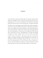
A sensor network is a group of sensor nodes which are communicate among each other.
Sensors are constrained in terms of memory and processing power because of their
limited physical size and cost. These constraints have been considered too limiting for
physical size sensor to be able to use the TCP/IP protocols. The purposed sensor node
has ability to sense environmental data such as humidity, light, weight, and temperature,
and has been ported with embedded TCP/IP protocol to perform the networking. The
sensor node is equipped with a small microcontroller, a RF communication module, a
sensor, and an energy source. This project was carried out to develop two nodes that also
able to sense the temperature .The sensors nodes are embedded with TCP/IP stack and
able to forward and receive data. The programming was developed with WinAVR
development tools using C language. The hex code will be ported using AVRISP
connector. Finally, the transmission of data between sensor nodes are measured and
displayed on computer using hyper terminal (mikroBASIC) and Visual Basic 6.0
interfacing. Each frame that transmitted contents 44 bytes data: 2 bytes header (link
layer); 1byte checksum (link layer); 20 bytes TCP header; 20 bytes IP header; and 1
byte data. All of those header were removed away to get the actual data. The result
during transmission was captured with oscilloscope to identify every bit in the frame.
vi
ABSTRAK
Rangkaian pengesan adalah sekumpulan nod-nod pengesan yang saling
berkomunikasi antara satu sama lain. Setiap nod pengesan dilengkapi dengan
mikropengawal yang kecil, modul perhubungan RF, pengesan, dan satu sumber tenaga.
Nod-nod pengesan ini terikat dari segi ingatan dan kuasa pemprosesan disebabkan oleh
kos dan saiz fizikal yang terhad. Ciri-ciri ini telah dipertimbangkan amat terhad bagi saiz
fizikal nod pengesan untuk berupaya menggunakan protokol TCP/IP. Nod pengesan
mempunyai kebolehan untuk mengesan data daripada persekitaran seperti kelembapan,
cahaya, berat dan suhu dan juga dolengkapi dengan protokol TCP/IP terbenam untuk
perangkaian. Projek ini telah untuk dijalankan untuk membangunkan dua modul nod
pengesan yang berupaya untuk mengesan nilai suhu, untuk memprogramkan tindanan
TCP/IP ke dalam nod pengesan dan berupaya untuk menghantar data kepada nod yang
seterusnya. Pengaturcaraan dibangunkan dengan sebuah perkakasan pembangunan
WinAVR. Kod perenambelasan diprogramkan melalui penghubung AVRISP. Akhir
sekali, penghantaran data di antara nod-nod pengesan ditentukan dan keputusan
dipaparkan di skrin komputer menggunakan perisian hyper terminal (mikroBASIC) dan
pengantaramuka Visual Basic 6.0. Setiap paket data uang dihantar nengandungi : 2 bait
kepala;2 bait checksum;20 bait kepala TCP ; 20 bait kepala IP ; dan 1 bait data. Semua
kepala ini ditapis untuk mendapatkan data. Data semasa penghantaran diukur
menggunakan osiloskop.
vii
TABLE OF CONTENTS
CHAPTER
1
2
TITLE
PAGE
TITLE
i
DECLARATION
ii
DEDICATION
iii
ACKNOWLEDGEMENT
iv
ABSTRACK
v
TABLE OF CONTENTS
vii
LIST OF TABLE
x
LIST OF FIGURE
xi
LIST OF ABBREVIATIONS
xiv
LIST OF APPENDICES
xvi
INTRODUCTION
1.1
Overview
1
1.2
Problem Statement
3
1.3
Objectives
3
1.4
Project Scope
4
BACKGROUND LITERATURE
2.1
Wireless Sensor Network
5
viii
3
2.2
Sensor Networks Applications
6
2.3
Factors Influencing Sensor Network Design
7
2.4
TCP/IP Protocol Suites
15
2.5
TCP/IP Stack
15
METHODOLOGIES
3.1
Introduction
18
3.2
Hardware Design
19
3.2.1 AVR Microcontroller
21
3.2.2
Analog Temperature sensor
22
3.2.3
Transmitter Node
24
3.2.4
Receiver Node
26
3.3
3.2.5 RF Communication
28
3.2.6 AVR ISP Cable
30
3.2.7 RS232 Serial Cable
32
Software Development
35
3.3.1
Transmitter Node
36
3.3.2
Receiver Node
39
3.3.3
uIP
41
3.3.4
Code Compiler (WinAVR)
45
3.3.5 Visual Basic 6.0
4
5
47
RESULT
4.1
Result from Oscilloscope
52
4.2
Results at Hyper Terminal
58
4.3
Results at Visual Basic 6.0 GUI
59
CONCLUSION AND RECOMMENDATION
5.1
Discussion
61
5.2
Recommendation
62
ix
REFERENCES
63
APPENDIX A
65
APPENDIX B
88
APPEBDIX C
94
x
LIST OF TABLES
NO
TITLE
PAGE
2.1
Frequency bands available for ISM applications
11
xi
LIST OF FIGURES
NO
TITLE
PAGE
1.1
Basic communication link of wireless sensor network
2.1
The components of sensor nodes
9
2.2
TCP/IP protocol suite
13
2.3
TCP/IP input processing
16
2.4
TCP/IP output processing
17
3.1
Methodologies’ diagram
19
3.2
Sensor node proposed designed
20
3.3
Pin out of ATmega8535
21
3.4
LM35 TO-202 package
23
3.5
Common used circuit for LM35 DZ
23
3.6
Transmitter node circuit
25
3.7
PCB circuit layout for transmitter node
25
3.8
PCB circuit for transmitter node
26
3.9
Receiver node circuit
27
3.10
PCB circuit layout for receiver node
27
3.11
PCB circuit for receiver node
28
3.12
Transmitter module
29
3.13
Receiver module
30
3.14
ISP cable circuit design
30
xii
3.15
PCB layout for ISP cable
31
3.16
ISP cable
32
3.17
RS232 DB9 pin out
33
3.18
Pin out of MAX232
33
3.19
Schematic circuit for RS232 serial cable
34
3.20
PCB layout for RS232 serial cable
34
3.21
RS232 serial cable
35
3.22
Steps in designing the code programming
36
3.23
Flowchart for transmitter node process
37
3.24
Flowchart for USART transmitter node process
38
3.25
Flowchart for receiver node process
39
3.26
Flowchart for USART receiver node process
40
3.27
Embedded software development process
41
3.28
Main source code for transmitter (uIP)
42
3.29
Main source code for receiver (uIP)
44
3.30
Programmer notepad in WinAVR
46
3.31
New project window
47
3.32
Visual basic design
48
3.33
Menu bars and title bars
48
3.34
Microsoft Comm Control 6.0
49
3.35
PonyProg2000 window
50
4.1
Observed Data Transmission using USART
(without uIP - wired)
4.2
Observed Data Transmission using USART
(with uIP – wired – before uIP process)
4.3
55
Observed Data Transmission using USART
(with uIP – wireless – before uIP process)
4.5
54
Observed Data Transmission using USART
(with uIP – wired – after uIP process)
4.4
53
56
Observed Data Transmission using USART
(with uIP – wireless – after uIP process)
57
xiii
4.6
Received Data Displayed at HyperTerminal
(USART - with uIP – wireless – before uIP process)
4.7
4.8
58
Received Data Displayed at HyperTerminal.
(USART - with uIP – wireless – after uIP process)
59
Graphical User Interface
60
xiv
LIST OF ABBREVIATIONS
ADC
Analog to Digital Conversion
AM
Amplitude Modulation
ARP
Address Resolution Protocol
AVR-GCC
AVR- GNU Compiler Collection
AVR RISC
AVR Reduced Instruction Set Computer
DHCP
Dynamic Host Configuration Protocol
DNS
Domain Name System
DTN
Delay Tolerant Network
EEPROM
Electrically Erasable Programmable Read Only Memory
FTP
File Transfer Protocol
GPRS
Global Packet Radio Service
HTTP
HyperText Transfer Protoco
ICMP
Internet Control Message Protocol
ISP
In-Circuit Serial Programmable
KB
Kilo Byte
LWIP
Light Weight Internet Protocol
LSB
Least Significant Bit
MHz
Megahertz
MSB
Most Significant Bit
OS
Operating System
PPP
Point-to-Point Protocol
RAM
Random Access Memory
xv
RF
Radio Frequency
Rx
Receiver
SLIP
Serial Line Interface Protocol
SMTP
Simple Mail Transport Protocol
SN
Sensor Network
SRAM
Static Random Access Memory
TCP/IP
Transmission Control Protocol/ Internet Protocol
Tx
Transmitter
UDP
User Datagram Protocol
USART
Universal Synchronous Asynchronous Receiver Transmitter
xvi
LIST OF APPENDICES
APPENDIX A : Transmitter And Receiver Node Source Codes
65
APPENDIX B : Malefile Source Codes
88
APPENDIX C : WinAVR Manual
94
CHAPTER 1
INTRODUCTION
1.1
Overview
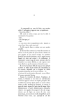
A communication between wireless sensor networks is an information gathering
paradigm based on the collective effort of many small wireless sensor nodes. The sensor
nodes, which are intended to be physically small and inexpensive, are equipped with one
or more sensor, a short range radio transceiver, a small microcontroller, and s power
supply in the form of a battery [A.Dunkles, J.Alonso, T.Voigt, 2004].
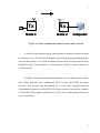
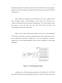
Figure 1.1 shows the basic communication link of wireless sensor network,
where the transmitter node is willing to forward the information to the target destination
and the received data will be displayed at the computer.
2
s
Tx
Rx
Node 1
Node 2
Computer
Figure 1.1 : Basic communication link of wireless sensor network
A wireless sensor network usually cannot operate in complete isolation, but must
be connected to an external network through which monitoring and controlling entities
can reach the sensornet. As TCP/IP, the Internet Protocol suite, has become the de-facto
standard for large scale networking, it is interesting to be able to connect sensornet to
TCP/IP networks.
A.Dunkles (2004) had discussed three different ways to connect sensor network
with TCP/IP networks: proxy architectures, DTN overlays, and TCP/IP for sensor
networks. They conclude that the methods are in some sense orthogonal and that
combinations are possible, but that TCP/IP for sensor networks currently has a number
of issues that require further research before TCP/IP can be viable protocol family for
sensor networking.
2
3
1.2
Problem Statement
Nowadays, sensor network becomes more important to human life whether for
security, monitoring or to minimize power consumption. This project was developed
because of the awareness to analyze sensor network system. Limited size of memory in a
small size microcontroller is said to be limited criteria to run TCP/IP protocol into
sensor nodes, thus through this project, we tried to embed uIP into AVR microcontroller.
uIP is a small TCP/IP stack. The data transmission was observed by using the RF
transmitter and also direct wire interface at the physical layer.
1.3
Objectives
The objectives of this project are:
1. To develop wireless sensor network that distribute/transfer environmental data
(eg: temperature) using TCP/IP protocol.
2. To embed the uIP, a TCP/IP stacks protocol into sensor nodes.
3
4
1.4
Project Scope
The scopes of work for this project are to develop sensor node (basic of the
sensor network) that able to do sensing, processing and networking using: Processor
(AVR microcontroller), Sensor type (Temperature sensor), Communication link (RF
transmitter and receiver module), Frequency involved (433 MHz), TCP/IP Protocol (uIP
stack). The microcontroller was programmed using C/C++, and then the source codes
were compiled using GNU tools, WinAVR (AVR-GCC). The data collected by the
analog temperature sensor was converted into digital representation (A/D Conversion).
The transmitter and receiver nodes (PCB board) were built with DXP 2004 software.
The AVRISP connector was built to program the INTEL hex code into the AVR
microcontroller. Then wrote a device driver for target’s network device in uIP (serial),
and configured the uIP codes to be used in the sensor device. After that, the uIP, a
TCP/IP functions was embedded into the sensor nodes. This is done to perform a
networking between sensor nodes. Then, the corresponding between sensor and
transmitter that transfer data trough TCP/IP were done. The temperature (result) was
displayed at the computer using Visual Basic 6.0 interfacing
4
CHAPTER 2
BACKGROUND LITERATURE
2.1
Wireless Sensor Network
Wireless sensor network are self-organizing wireless networks where all nodes
take part in the process of forwarding packets. These tiny sensor nodes, which consist of
sensing, data processing, and communicating components, leverage the idea of sensor
networks based on collaborative effort of a large number of nodes. Sensor networks
represent a significant improvement over traditional sensors. A sensor network is
composed of a large number of sensor nodes, which are densely deployed either inside
the phenomenon or very close to it.
On the other hand, this also means that sensor network protocols and algorithms
must possess self-organizing capabilities. Another unique feature of sensor networks is
the cooperative effort of sensor nodes. Sensor nodes are fitted with an on-board
processor. Instead of sending the raw data to the nodes responsible for the fusion, sensor
6
nodes use their processing abilities to locally carry out simple computations and transmit
only the required and partially processed data.
Since large numbers of sensor nodes are densely deployed, neighbor nodes may
be very close to each other. Furthermore, the transmission power levels can be kept low,
which is highly desired in covert operations.
2.2
Sensor Networks Applications
Sensor networks may consist of many different types of sensors such as seismic,
low sampling rate magnetic, thermal, visual, infrared, acoustic, and radar, which are able
to monitor a wide variety of ambient conditions that include the temperature, humidity,
vehicular movement, lightning condition, pressure, soil makeup, noise levels, the
presence or absence of certain kinds of objects, mechanical stress levels on attached
objects, and the current characteristics such as speed, direction, and size of an object.
Sensor nodes can be used for continuous sensing, event detection, event ID,
location sensing, and local control of actuators. The concept of micro-sensing and
wireless connection of these nodes promises many new application areas. The
applications were categorized into military, environment, health, home and other
commercial areas. It is possible to expand this classification with more categories such
as space exploration, chemical processing and disaster relief.
7
2.3
Factors Influencing Sensor Network Design
L.F. Akyildiz (2001) had discussed that a sensor network design is influenced by
many factors, which include fault tolerance; scalability; production costs; operating
environment; sensor network topology; hardware constraints; transmission media; and
power consumption. These factors are addressed by many researchers as surveyed in the
paper. However, none of these studies has a full integrated view of all factors that are
driving the design of sensor networks and sensor nodes. These factors are important
because they serve as a guideline to design a protocol or an algorithm for sensor
networks. In addition, these influencing factors can be used to compare different
schemes.
2.3.1
Fault tolerance
Fault tolerance is the ability to sustain sensor network functionalities without any
interruption due to sensor node failures. Some sensor nodes may fail or be blocked due
to lack of power, have physical damage or environmental interference. The failure of
sensor nodes should not affect the overall task of the sensor network. This is the
reliability or fault tolerance issue. As a result, the fault tolerance level depends on the
application of the sensor networks, and the schemes must be developed with this in
mind.
2.3.2
Scalability
The number of sensor nodes deployed in studying a phenomenon may be in the
order of hundreds or thousands. Depending on the application, the number may reach an
8
extreme value of millions. The new schemes must be able to work with this number of
nodes. They must also utilize the high density nature of the sensor networks.
2.3.3
Production costs
Since the sensor networks consist of a large number of sensor nodes, the cost of a
single node is very important to justify the overall cost of the networks. If the cost of the
network is more expensive than deploying traditional sensors, then the sensor network is
not cost-justified. As a result, the cost of each sensor node has to be kept low.
2.3.4
Hardware constraints
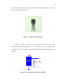
A sensor node is made up of four basic components as shown in Fig. 2.1: a
sensing unit, a processing unit, a transceiver unit and a power unit. They may also have
application dependent additional components such as a location finding system, a power
generator and a mobilizer. Sensing units are usually composed of two subunits: sensors
and analog to digital converters (ADCs). The analog signals produced by the sensors
based on the observed phenomenon are converted to digital signals by the ADC, and
then fed into the processing unit. The processing unit, which is generally associated with
a small storage unit, manages the procedures that make the sensor node collaborate with
the other nodes to carry out the assigned sensing tasks. A transceiver unit connects the
node to the network. One of the most important components of a sensor node is the
power unit. Power units may be supported by a power scavenging unit such as solar
cells.
9
Figure 2.1 : The components of a sensor node.
Though the higher computational powers are being made available in smaller and
smaller processors, processing and memory units of sensor nodes are still scarce
resources. For instance, the processing unit of a smart dust mote prototype is a 4 MHz
Atmel AVR8535 micro-controller with 8 KB instruction flash memory, 512 bytes RAM
and 512 bytes EEPROM [66]. TinyOS operating system is used on this processor, which
has 3500 bytes OS code space and 4500 bytes available code space.
2.3.5
Sensor network topology
Sheer numbers of inaccessible and unattended sensor nodes, which are prone to
frequent failures, make topology maintenance a challenging task. Hundreds to several
thousands of nodes are deployed throughout the sensor field. They are deployed within
tens of feet of each other. The node densities may be as high as 20 nodes/m3. Deploying
high number of nodes densely requires careful handling of topology maintenance.
10
2.3.6
Environment
Sensor nodes are densely deployed either very close or directly inside the
phenomenon to be observed. Therefore, they usually work unattended in remote
geographic areas. They may be working in busy intersections, in the interior of a large
machinery, at the bottom of an ocean, inside a twister, on the surface of an ocean during
a tornado, in a biologically or chemically contaminated field, in a battlefield beyond the
enemy lines, in a home or a large building, in a large warehouse, attached to animals,
attached to fast moving vehicles, and in a drain or river moving with current.
This list gives us an idea about under which conditions sensor nodes are expected
to work. They work under high pressure in the bottom of an ocean, in harsh
environments such as debris or a battlefield, under extreme heat and cold such as in the
nozzle of an aircraft engine or in arctic regions, and in an extremely noisy environment
such as under intentional jamming.
2.3.7
Transmission media
In a sensor network, communicating nodes are linked by a wireless medium.
These links can be formed by radio, infrared or optical media. To enable global
operation of these networks, the chosen transmission medium must be available
worldwide. One option for radio links is the use of industrial, scientific and medical
(ISM) bands, which offer license-free communication in most countries. The
International Table of Frequency Allocations contained in Article S5 of the Radio
11
Regulations (Volume 1), species some frequency bands that may be made available for
ISM applications. They are listed in Table 2.2.
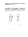
For sensor networks, a small-sized, low-cost, ultra low power transceiver is
required. According to [68], certain hardware constraints and the trade-off between
antenna efficiency and power consumption limit the choice of a carrier frequency for
such transceivers to the ultrahigh frequency range. They also propose the use of the 433
MHz ISM band in Europe and the 915 MHz ISM band in North America.
Table 2.1 : Frequency bands available for ISM applications
2.3.8
Power consumption
The wireless sensor node, being a micro-electronic device, can only be equipped
with a limited power source. In some application scenarios, replenishment of power
12
resources might be impossible. Sensor node lifetime, therefore, shows a strong
dependence on battery lifetime. In a ad hoc sensor network, each node plays the dual
role of data originator and data router. The disfunctioning of few nodes can cause
significant topological changes and might require re-routing of packets and reorganization of the network. Hence, power conservation and power management take on
additional importance. It is for these reasons that researchers are currently focusing on
the design of power-aware protocols and algorithms for sensor networks.
2.4
TCP/IP Protocol Suites
TCP/IP is a Transmission Control Protocol/Internet Protocol. It is the most
popular network protocol and the basis for the internet. TCP/IP protocol suite consists of
a large collection of protocols that have been issued as Internet standards by the Internet
Architecture Board (IAB). The protocol stack used by the sink and all sensor nodes is
given in Fig. 3. This protocol stack combines power and routing awareness, integrates
data with networking protocols, communicates power efficiently through the wireless
medium, and promotes cooperative efforts of sensor nodes.
TCP/IP has 5 layers; Physical layer, Network Access layer, Internet layer, Hostto-host layer known as transport layer and Application layer that shown in Figure 2.3.
Each layer has its own function on transmitting data.
13
TCP/IP
Layers
TCP/IP Protocol Suite
Application
Telnet FTP SMTP
DNS POP3SNMP
Transport
TCP
UDP
ICMP IGMP OSPF
IP
Internet
Network Access
802.2
LLC
Physical
Ethernet
PPP
SLIP
NON STANDART
Serial Port
Figure 2.2 : TCP/IP Protocol Suite
Physical Layer
It covers the physical interface between data transmission device and a
transmission medium or network. The internet protocol suite does not cover the physical
layer of any network. The physical layer is responsible for frequency selection, carrier
frequency generation, signal detection, modulation and data encryption.
Network Access layer
Network access layer solved the problem of getting packet across a single
network. Examples of such protocol are X.25 and Arpanet’s Host/IMP Protocol. The
network access layer is responsible for the multiplexing of data streams, data frame
detection, medium access and error control. It ensures reliable point-to-point and pointto-multipoint connections in a communication network. In this project, the non standard
format is used.
14
Internet layer
In the internet layer, IP performs the basic task of getting packet of data from
source to destination.
Transport layer
This layer is used in exchanging data and ensures that data arrives in the correct
destination. In TCP/IP protocol suite, transport layer also determine which application
any give data is intended for. This layer is especially needed when the system is planned
to be accessed through Internet or other external networks.
Application layer
The application layer is the most common network-aware programs
interface use in order to communicate across a network with other programs. Designing
an application layer management protocol has several advantages. Sensor networks have
many different application areas, and accessing them through networks such as Internet
is aimed in some current projects [69]. An application layer management protocol makes
the hardware and software of the lower layers transparent to the sensor network
management applications.
15
2.5
TCP/IP Stack
Nowadays, the TCP/IP protocol suite has become a global standard for
communication. TCP/IP is the underlying protocol used for web page transfers, e-mail
transmissions, file transfers, and peer-to-peer networking over the Internet. For
embedded systems, being able to run native TCP/IP makes it possible to connect the
system directly to an intranet or even the global Internet. Embedded devices with full
TCP/IP support will be first-class network citizens, thus being able to fully communicate
with other hosts in the network.
Traditional TCP/IP implementations have required far too much resource both in
terms of code size and memory usage to be useful in small 8 or 16-bit systems. Code
size of a few hundred kilobytes and RAM requirements of several hundreds of kilobytes
have made it impossible to fit the full TCP/IP stack into systems with a few tens of
kilobytes of RAM and room for less than 100 kilobytes of code. TCP is both the most
complex and the most widely used of the transport protocols in the TCP/IP stack. TCP
provides reliable full-duplex byte stream transmission on top of the best-effort IP layer.
Because IP may reorder or drop packets between the sender and the receiver, TCP has to
implement sequence numbering and retransmissions in order to achieve reliable, ordered
data transfer.
A.Dunkles (2004) had discussed that there are two small generic and portable
TCP/IP implementations, lwIP (lightweight IP) and uIP (micro IP), with slightly
different design goals. The lwIP implementation is a full-scale but simplified TCP/IP
implementation that includes implementations of IP, ICMP, UDP and TCP and is
modular enough to be easily extended with additional protocols. lwIP has support for
multiple local network interfaces and has a flexible configuration option which makes it
suitable for a wide variety of devices. The uIP implementation is designed to have only
16
the absolute minimal set of features needed for a full TCP/IP stack. It can only handle a
single network interface and does not implement UDP, but focuses on the IP, ICMP and
TCP protocols.
From a high level viewpoint, the TCP/IP stack can be seen as a black box that
takes incoming packets, and demultiplexes them between the currently active
connections. Before the data is delivered to the application, TCP sorts the packets so that
they appear in the order they were sent. The TCP/IP stack will also send
acknowledgments for the received packets.
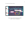
Figure 2.4 shows how packets come from the network device, pass through the
TCP/IP stack, and are delivered to the actual applications. In this example there are five
active connections, three that are handled by a web server application, one that is
handled by the e-mail sender application and one that is handled by a data logger
application.
Figure 2.3 : TCP/IP input processing.
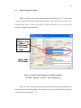
A high level view of the output processing can be seen in Figure 2.5. The TCP/IP
stack collects the data sent by the applications before it is actually sent onto the network.
17
TCP has mechanisms for limiting the amount of data that is sent over the network, and
each connection has a queue on which the data is held while waiting to be transmitted.
The data is not removed from the queue until the receiver has acknowledged the
reception of the data. If no acknowledgment is received within a specific time, the data
is retransmitted.
Figure 2.4 : TCP/IP output processing.
Data arrives asynchronously from both the network and the application, and the
TCP/IP stack maintains queues in which packets are kept waiting for service. Because
packets might be dropped or reordered by the network, incoming packets may arrive out
of order. Such packets have to be queued by the TCP/IP stack until a packet that fills the
gap arrives. Furthermore, because TCP limits the rate at which data that can be
transmitted over each TCP connection, application data might not be immediately sent
out onto the network.
CHAPTER 3
METHODOLOGIES
3.1
Introduction
This chapter describes methodology of developing the sensor nodes and in this
project, it were divided into two sections; hardware design and software development.
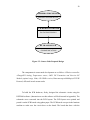
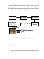
The discussion is started with hardware design and software development. Figure 3.1 is
shown the diagram of the methodologies. The sensor nodes were simply designed to
able provide sensing and networking. As was explained in previous chapter, a sensor
network normally consist a large number of sensors. However for this project, the sensor
network development was carried out for only two nodes. Thus, the data transmission
will be verified between these sensor nodes.
19
Temperature
Sensor
Sensing
Hardware
Design
Processing
Software
Development
Communication
RF Module
Figure 3.1 : Methodologies’ Diagram
3.2
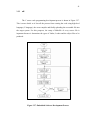
Hardware Design
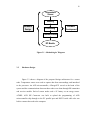
Figure 3.2 shows a diagram of the proposed design architecture for a sensor
node. Temperature sensor were used to capture data from surroundings, and interfaced
to the processor. An AVR microcontroller, ATmega8535 served as the brain of the
system and the communications between these nodes were done through RF transmitter
and receiver module. Each of sensor nodes used a 9V battery as an energy source.
ATMEL AVR ISP Connector was built to upload the programming of AVR
microcontroller chip through to the PC parallel port and RS232 serial cable also was
built to connect the node to the computer.
20
TEMPERATURE SENSOR
SENSE/CAPTURE DATA
AVR MICROCONTROLER
DATA PROCESSING
RF TRANSCEIVER
COMMUNICATION
Figure 3.2 : Sensor Node Proposed Design
The components in sensor node development are as follow: AVR microcontroller
ATmega8535:Analog Temperature sensor, LM35 DZ Transmitter and Receiver RF
Module (optimal range 100m, 433.92MHz version, Data rates up to 4800 bps)A TCP/IP
Protocol, uIP stack in each sensor nodes
To build the PCB hardware, firstly, designed the schematic circuits using the
DXP2004 software. (Instruction to use this software will be discussed in Appendix). The
schematics were converted into the PCB layouts. The PCB layouts were printed and
pasted it on the PCB boards using photo paper. The PCB boards were put in the laminate
machine to make sure the circuit drew on the board. The board that drew with the
21
schematic was put in the itching machine. After that, the boards were cleaned with
thinner. Lastly, the boards were drilled and the devices were completed by soldering the
equipment on the boards.
3.2.1
AVR Microcontroller
An 8 bit AVR RISC micro-controller was used as the brain of the sensor node as
referred in [S.Hollar, 2000]. ATMEL ATmega8535 had 8K bytes of In-System
Programmable Flash with Read-While-Write capabilities, 512 bytes EEPROM, 512
bytes SRAM, 32 I/O lines, execution rate of one instruction per clock and can be
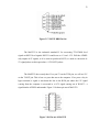
attached to a PC ISA – bus network. Figure 3.3 shows Pin out of ATmega8535.
Figure 3.3 : Pin out of ATmega8535
22
ATmega8535 supports ADC conversion start on auto-triggering on interrupt
sources. All of the registers are directly connected to the Arithmetic Logic Unit (ALU),
allowing two independent registers to be accessed in one single instruction executing in
one clock cycle. In this project, the AVR ATmega8535 was used to take analog data
from temperature sensor and convert them into digital representation.
The Universal Synchronous and Asynchronous serial Receiver and Transmitter
(USART) is used in this project as it is a highly flexible serial communication device.
The data frame format that used is 1 start bit; 8 data bits; 1 stop bit. The Transmitter
consists of a single write buffer and a serial Shift Register. The write buffer allows a
continuous transfer of data without any delay between frames. The Receiver is more
complex than the Transmitter. The Receiver consists a Shift Register and a two level
receive buffer (UDR).
3.2.2
Analog Temperature sensor
The LM35 is an integrated circuit sensor that can be used to measure temperature
with an electrical output proportional to the temperature (in oC). It has an output voltage
that is proportional to the Celsius temperature. The scale factor is .01V/oC. The LM35
does not require any external calibration or trimming and maintains an accuracy of +/0.4 oC at room temperature and +/- 0.8 oC over a range of 0 oC to +100 oC. Another
important characteristic of the LM35DZ is that it draws only 60 micro amps from its
supply and possesses a low self-heating capability. The sensor self-heating causes less
than 0.1 oC temperature rise in still air. The LM35 comes in many different packages,
including the following: TO-92 plastic transistor-like package, T0-46 metal can
23
transistor-like package, 8-lead surface mount SO-8 small outline package and TO-202
package. (Shown in the figure 3.4)
Figure 3.4 : LM335 TO-202 package.
Figure 3.5 shows the common used circuit for the sensor. In this circuit,
parameter values commonly used are: Vc = 4 to 30v. But, 5v or 12 v are typical values
used and Ra = Vc /10-6. Actually, it can range from 80 KW to 600 KW, but most just use
80 KW.
Figure 3.5 : Common Used Circuit for LM35 DZ
24
The output voltage is converted to temperature by a simple conversion factor.
The sensor has a sensitivity of 10mV / oC. Use a conversion factor that is the reciprocal
that is 100V / oC. The general equation used to convert output voltage to temperature is:
Temperature ( oC) = Vout * (100 oC/V). So if Vout is 1V , then, Temperature = 100
o
C. The output voltage varies linearly with temperature.
3.2.3
Transmitter Node
Figure 3.6 shows the circuit constructed for the transmitter node that consists: a
microcontroller; a temperature sensor; a voltage regulator and other passive
equipment. The basic equipments for this microcontroller are the reset button and the
oscillator circuit. The purpose of the reset button is to reset the program that embedded
in the microcontroller and it consists of a reset button, a resistor and a capacitor.
Besides, 8 MHz crystal oscillator is used to generate clocking for the microcontroller
and it consists two capacitors for stability. Voltage regulator is used to regulate the 9V
input voltage to 5V as the microcontroller circuit is powered by 5V. The circuit cannot
directly powered by 5V without using the voltage regulator, it is because the circuit will
not stable. The analog temperature sensor is connected to PORTA pin 5 and the
transmitter module is attached to TXD pin at PORTD. The program is uploaded into the
microcontroller through these pins: MISO, MOSI, SCK, and RESET.
25
Figure 3.6: Transmitter Node Circuit.
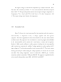
Figure 3.7 shows the PCB layout for transmitter node. Double layer PCB circuit
was implemented for this node because of the complexity.
Figure 3.7: PCB Circuit Layout for Transmitter Node
26
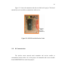
Figure 3.8 shows the transmitter node that was built in this project. This board
attached by transmitter module to communicate with receiver.
Figure 3.8: PCB Circuit for Transmitter Node
3.2.4
Receiver Node
Figure 3.9 shows the circuit constructed for the receiver node that consists: a
microcontroller; eight LEDs to show the output; a voltage regulator and other passive
equipment. The basic equipments for this microcontroller are totally same to the
transmitter. The output LEDs are connected to PORTC. The 220 Ohm resisters that
connected series to the LEDs are used to reduce some voltage before going through the
LEDs.
27
Figure 3.9: Receiver Node Circuit.
Figure 3.10 shows the PCB layout for receiver node. Double layer PCB circuit
also was implemented for this node because of the complexity.
Figure 3.10: PCB Circuit Layout for Receiver Node
28
Figure 3.11 shows the transmitter node that was built in this project. This board
attached by receiver module to communicate with receiver.
Figure 3.11: PCB Circuit for Receiver Node
3.2.5
RF Communication
The wireless sensor network needs transmitter and receiver module to
communicate between nodes. So, in this project, the transmitter and receiver module
from RADIOTRONIX are used to the purpose.
29
3.2.5.1 Transmitter Module
The RCT-433-AS is ideal for sensor network applications where low cost and
longer range is required. The transmitter operates from a 1.5-12V supply, making it ideal
for battery-powered applications. The transmitter employs a Surface Acoustic Wave
(SAW)-stabilized oscillator, ensuring accurate frequency control for best range
performance. Output power and harmonic emissions are easy to control. Figure 3.12
shows the transmitter module.
Figure 3.12: Transmitter Module
3.2.5.2 Receiver Module
The RCR-433-HP is ideal for sensor network applications where low cost and
longer range are required. The receiver module requires no external RF components
except for the antenna. The super-heterodyne design exhibits exceptional sensitivity and
selectivity. A SAW filter can beaded to the antenna input to improve selectivity for
applications that require robust performance. Figure 3.13 shows the receiver module.
30
Figure 3.13: Receiver Module
3.2.6
AVR ISP Cable
AVR ISP (In System Programmable) Cable is used for uploading the hex into the
microcontroller directly. The circuit diagram of ISP Cable is shown in figure 3.14 that
can be built easily. The equipment that needed to built the cable are: connector;
74LS245 chip; DB25; and other passive equipment.
Figure 3.14: ISP Cable Circuit Design
31
The ISP has only four signals to be implemented, which are MOSI, MISO, SCK
and RESET. LED1 is as a indicator to detect the programmer either on or off. The LED
turned on when PC started up and during the uploading. Otherwise, there might be some
error occurred. The 74LS245, an octal tri-state buffer was used as the main component,
makes the operation is extremely simple. It was used to provide the float state after the
hex code has been written into the AVR chip. The two loop-back connections, pin 2 to
12 and 3 and 11 is used to identify the ISP cable or so called as dongle. With both links
in place the dongle is identified as a Value Added Pack Dongle.
Figure 3.15 shows the PCB layout for the cable. The simple circuit like this only
needs a single layer PCB circuit
Figure 3.15: PCB Layout for ISP Cable
32
Figure 3.16 shows the ISP Cable that built in this project. The cable is in small
size and robust when built it as PCB circuit.
Figure 3.16: ISP Cable
3.2.7
RS232 Serial Cable
In this project, the DB9 version is used. Figure 3.17 shows the signals common
for DB9 version. Note, that the protective ground is assigned to a pin at the large
connector where the connector outside is used for that purpose with the DB9 connector
version.
33
Figure 3.17: RS232 DB9 Pin Out
The MAX232 is the industrial standard IC for converting TTL/CMOS level
signals to RS232 level signals. RS232 1s and 0s are at +12 and - 12V. Well the ATMEL
only outputs 0-5V signals, so if we want to speak true RS232, we need to convert the 05V signal pulses to their equivalent +/-12V RS232 pulses.
The MAX232 does exactly that. If we put 5V on the T1IN pin, we will see 12V
on the T1OUT pin. This is how we pass data out to the computer. If we press a key in
hyper terminal, a signal is sent down the line to the R1IN pin where the 12V signal
coming from the computer is converted to a 0/5V signal coming out of R1OUT - a
signal that the ATMEL understands. Figure 3.18 shows pin out of MAX232.
Figure 3.18: Pin out of MAX232
34
Figure 3.19 shows the schematic for the RS232 serial cable. The components that
needed to build the cable are: MAX232 chip, DB9 connector; and four capacitors.
VCC
C8
C5
1uF
1uF
1
3
4
5
C6
ATMELTX
1uF
11
10
12
9
15
C1+
C1C2+
C2T1IN
T2IN
VDD
VCC
T1OUT
T2OUT
R1OUT
R2OUT
R1IN
R2IN
GND
VEE
2
16
J1
14
7
13
8
C7
6
1
6
2
7
3
8
4
9
5
11
10
DConnector 9
MAX232
1uF
Figure 3.19: Schematic Circuit for RS232 serial Cable
Figure 3.20 shows the PCB layout for the cable. A single layer PCB circuit also
used for this simple circuit.
Figure 3.20: PCB Layout for RS232 Serial Cable
35
Figure 3.21 shows the complete RS232 that used in this project.
Figure 3.21: RS232 Serial Cable
3.3
Software Development
In this project, the code programming was written in C language. First, we had to
configure which registers will be used and setup specific pins for transmitting and
receiving the data. Then, we drew the flowcharts for sensor nodes architecture as a guide
to write the program code. In this project, the code of temperature sensing, data transmit
and receive, and also the main loop in which we have to define the timer driver and the
device driver were developed.
After that, those codes need to be compiled using a window platform of
AVRGCC, WinAVR as it can handled the compiling, debugging and created the hex
code as well. Figure 3.10 shows the steps in designing the code programming. After
36
compiling, the hex file that produced was uploaded into the chip using PonyProg2000.
The analog temperature that measured by the sensor firstly converted into digital value
before transmitting, and the received data were displayed at computer using Visual Basic
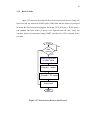
interfacing. Figure 3.22 shows the flow in designing the code programming.
Programming
Code using
C/C++
Application’s
Flowchart
Upload Code
To target Device
(PonyProg2000)
Get Hex File
Setup Makefile
Compile using
WinAVR
ISP CABLE
RS232
CABLE
(GUI – VB 6.0)
Figure 3.22 : Steps in designing the code programming.
3.3.1
Transmitter Node
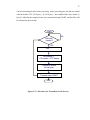
Figure 3.23 shows the flowchart for the overall transmitter node process. Firstly,
the analogue value from the temperature sensor was measured and the value was
37
converted into digital value before processing. In the processing part, the data was added
with the header (TCP [20 bytes] + IP [20 bytes] + non standard link layer header [3
bytes]). After that the complete frame were transmitted using USART, and this flow will
be repeated for the next data.
START
Get input
(sensor)?
NO
YES
ADC
UIP process =
+ IP header + TCP header
+ header & cksum
for link layer
Transmit using USART
END
Figure 3.23 : Flowchart for Transmitter Node Process
38
3.3.1.1 USART for Transmitter Node
Figure 3.24 shows flowchart to transmit data using USART program. First, all
parameters used in the program such as baud rate and frequency oscillator were defined.
Then, we initialize USART where we set the frame format for data transmission (1 start
bit; 8 data bits; and 1 stop bit) and activate the transmitter (TXD) pin. Then, after
getting the data, we had to make sure that the transmitter buffer was empty to allow the
transmitting.
START
USART
initialization
NO
ADC
Conversion Complete?
YES
NO
Wait for empty
tx buffer
YES
Transmit data
From USART buffer
END
Figure 3.24 : Flowchart for USART Transmitter Node Process
39
3.3.2
Receiver Node
Figure 3.25 shows the flowchart for the overall receiver node process. Firstly, the
frame received was read from USART buffer (UDR).After that the frame was processed
to extract the data. In the processing part, the header (TCP [20 bytes] + IP [20 bytes] +
non standard link layer header [3 bytes]) were separated from the data. Lastly, the
complete frame were transmitted using USART, and this flow will be repeated for the
next data.
START
NO
Data
receive?
YES
Read incoming data
In USART buffer
Checksum, - header
UIP process =
- IP header – TCP header
Display data
END
Figure 3.25 : Flowchart for Receiver Node Process
40
3.3.2.1 USART for Transmitter Node
Figure 3.26 shows flowchart to receive data using USART. First, all parameters
used in the program such as baud rate and frequency oscillator were defined. Then, we
initialize USART where we set the frame format for data transmission (1 start bit; 8
data bits; and 1 stop bit) as at the transmitter and activate the receiver (RXD) pin. Then,
if there were data received, the data could be read from the USART buffer.
START
USART
initialization
NO
Wait for data
to be received
YES
Read data
from USART buffer
END
Figure 3.26 : Flowchart for USART Receiver Node Process
41
3.3.3
uIP
The C source code programming development process is shown in Figure 3.27.
This is more details as it lists all the process from creating the code using high-level
language (C language), the cross-compiler and finally uploading the executable file into
the target system. For this purposes, the setup of Makefile of every source file is
important because it determines the types of Linker, Loader and the object files to be
produced.
Figure 3.27: Embedded Software Development Process
42
3.3.3.1 uIP Program Explanation
The main program for uIP is main.c, where this program was included with all
header file that used to call all functions for uIP programming. In this part, we will
discuss the code line by line in main.c.
3.3.3.1.1
Transmitter Part
Figure 3.28 shows the main source code for uIP stack for transmitter node.
Figure 3.28: The Main Source Code for uIP for Transmitter
43
This programming functions to control all of the transmitter tasks. In this part,
the programming code description in main.c will be described. Firstly, int main(void)
means the beginning of the program execution. While rs232dev_init( ) used to initialize
the rs232 device and set the parameter of the device which is in source code rs232_tty.
The uip_init( ) functions call the subroutine to check available ports and connection
configure the uIP data structures and example1_init( ) functions call the function to
defined port number for the application node. Both transmitter and receiver should have
the same port number. Besides, uip_process(UIP_DATA) means the actual uIP function
which does all the work such as to add the TCP/IP header and so on.
Whereas, *uip_appdata = acd( ) is a pointer points to the application data when
the application (from ADC conversion) is called. If the application wishes to send data,
this is where the application should write it. The rs232dev_send are functions to sends
the packet in the uip_buf and uip_appdata buffers. The first 40 bytes of the packet (the
IP and TCP headers) are read from the uip_buf buffer, and the following bytes (the
application data) are read from the uip_appdata buffer. After sending one packet, the
delay_1ms(1000) was called to make delay one second before transmitting next frame.
Lastly is return 0 means the end of the program
44
3.3.3.1.2
Receiver Part
Figure 3.29 shows the main source code for uIP stack for receiver node.
Figure 3.29: The Main Source Code for uIP for Receiver
This programming functions to control all of the receiving tasks. In this part, the
programming code description in main.c will be described. As in the transmitter part, int
main (void) means the beginning of the program execution. DDRC is a PORTC Data
Direction Register. DDRC = 0XFF means the PORTC Data Direction Register was set
to high to active the register. Besides, PORTC =0X00 means PORTC was set to low ( as
45
an output) to display the received data. After that, c= USART_RX( ) function called to
read the incoming packet from USART buffer. Whereas, process( ) calls the subroutine
to process the incoming packet. This function will extract the 8 bits data from the whole
frame. Lastly is return 0 means the end of the program
3.3.4
Code Compiler (WinAVR)
In developing and compiling the source code, several software that available for
free download from the net can be used. The source code was written in C, thus Visual
C++ or any other C programmer could be used. But in compiling the code, another
compiler that is more convenient for AVR microcontroller was used to compile the
code. The selection of software in compiling the code developed depends on the easiest
way and without the need of circuit emulator from the vendor. To program the code into
the chip, an alternative way such as an ISP connector can be implemented. The
followings are the software that might be use as the code compiler as well.
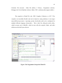
Figure 3.30 shows the Programmer Notepad window in WinAVR. In Figure
3.30, the source code is displayed at the back, while the front window shows the
makefile setup for the source code. After that, the source code will be executed by
hitting Make All command in the Tool menu. WinAVR is a suite of executable, open
source software development tools for the ATMEL series of RISC microprocessor
hosted on the Windows platform. It includes the GNU GCC compiler for C and C++. So
far, Win AVR supports only the DOS command-line platform. The user should familiar
with DOS commands before using it. The user needs to study the Makefile and AVRGCC program. WinAVR development tools includes Compilers , Assembler, Linker ,
46
Librarian, File converter , Other file utilities, C Library , Programmer software,
Debugger, In-Circuit Emulator software, Editor / IDE , and many other support utilities.
The compiler in WinAVR is the GNU Compiler Collection, or GCC. This
compiler was incredibly flexible and can be hosted on many platforms; it can target
many different processors / operating systems (back-ends), and can be configured for
multiple different languages (front-ends). . This is ideal for calling the make utility,
which executes user’s Makefile, which in turn calls the compiler, linker, and other
utilities used to build your software.
Figure 3.30: Programmer Notepad in WinAVR
47
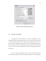
3.3.5
Visual Basic 6.0
Visual Basic 6.0 is used to design graphical user interface (GUI). This software
is ease to use and implement as it provides functional ability in the software. The Visual
Basic Integrated Development Environment (IDE) provides everything that is needed to
develop applications in an easy-to-use-and-learn GUI. This is the example of opening
screen that will appear in Visual Basic 6.0 software. Figure 3.31 shows the New Project
Window is displayed when Visual Basic is started.
Figure 3.31: The New Project Window
The codes provides in this software is user friendly and not complicated as the
other software because it use the Basic Language. Figure 3.32 shows the Menu Bars and
figure 3.33 shows the Title Bars provide information similar to most windows programs.
48
Figure 3.32: Visual Basic design
Figure 3.33: Menu Bars and Title Bars
Microsoft Comm Control 6.0 needs to be added in to Toolbox as illustrates in
figure 3.34. This tool is important in order to communicate with serial port.
49
Figure 3.34: Microsoft Comm Control 6.0
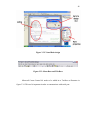
3.3.6
Serial Device Programmer
To program the AVR microcontroller, a serial device programmer was used
(PonyProg2000). Before programming the chip, we had to setup the interface whether to
use serial or parallel connector. Then, calibrate the bus timing, choose the device to be
used and setup the configuration and security bits. After all calibration and setting were
done, the chosen hex file could be uploaded into the microcontroller. Before that, we had
to ensure that we had chosen the right memory location for the programming which is
flash memory.
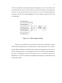
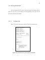
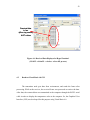
Figure 3.35 illustrates PonyProg2000 window. It shows the hex file, which tells
us the size of the program and the last memory that the program use. When the program
50
is successfully uploaded into microcontroller, it will show a notice that the program is
successful
the content
in the memory.
(memory filled
with hex code)
Code has been
downloaded into
Controller
successfully
Figure 3.35: PonyProg2000 window
CHAPTER 4
RESULT
The goal of this project is to distribute the basic of wireless sensor network that
can measure the temperature in different parts of the office to help in controlling the air
flow. Finally, this project was succeeding to transmit and receive data implementing
TCP/IP protocol. In this section we will discuss the result from experiments in this
project. The results were measure with an oscilloscope and were displayed at hyper
terminal and Visual Basic 6.0 GUI.
In view of the fact that it is data transmission between two sensor nodes, frame
formats and data rate is important. In this project, it was defined that data transmission
using USART with baud rate of 4800 bps, 8 bit frame format and Big Endian byte order
of the data. The data rate was described by the number of bits transmitted each second,
measured in bit per second (bps). Each frame contents 44 bytes data: 2 bytes header
(link layer); 1byte checksum (link layer); 20 bytes TCP header; 20 bytes IP header; and
1 byte data.
52
4.1
Result from Oscilloscope
The result will be elaborated in this section; which are analog data that has been
converted into the digital form. In this section, the result during transmission was
captured with oscilloscope to identify every bit in the frame.
4.1.1
USART without uIP Wired
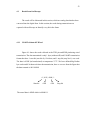
Figure 4.1 shows the result collected at the TXD pin and RXD pin during wired
transmission. The data transmitted is only 1 byte (without uIP) and USART transmission
format that have 1 start bit (star bit=0), 8 bit data, and 1 stop bit (stop bit=1) was used.
The data is 0X0E (in hexadecimal) at temperature 23 oC. We have defined Big Endian
byte order and 8 bit data each time the transmission, here we can see from the figure that
the data transmit is 0011100001
0 | 0111 | 0000 | 1
Start bit
0XE
The actual data is 0X0E which is 00000111.
0X0
Stop bit
53
Start bit=0
Stop bit=1
Tx
Data=0x0E (27 Celsius)
Rx
Figure 4.1: Observed Data Transmission using USART (without uIP - wired)
4.1.2
USART with uIP Wired
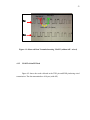
Figure 4.2 shows the result collected at the TXD pin and RXD pin during wired
transmission. The data transmitted are 44 bytes (with uIP).
54
Stop bit = 1
Start bit = 0
Tx
0xFC : 1 byte of 44 bytes
Rx
Figure 4.2: Observed Data Transmission using USART
(with uIP – wired – before uIP process)
Figure 4.3 shows the result collected at the TXD pin and RXD pin during wired
transmission. The data transmitted are 44 bytes (with uIP) and USART transmission
format that have 1 start bit (star bit=0), 8 bit data, and 1 stop bit (stop bit=1) was also
used. The data is 0X0F (in hexadecimal) at temperature 29 oC. We have defined Big
Endian byte order and 8 bit data each time the transmission, the extracted data is
0111100001
0 | 1111 | 0000 | 1
Start bit
0XF
. The actual data is 0X0F which is 00001111.
0X0
Stop bit
55
Tx
Data = 0x0F, 29 Celsius
Stop bit = 1
Start bit = 0
Rx
Figure 4.3: Observed Data Transmission using USART
(with uIP – wired – after uIP process)
4.1.3
USART with uIP Wireless
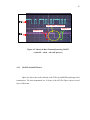
Figure 4.4 shows the result collected at the TXD pin and RXD pin during wired
transmission. The data transmitted are 44 bytes (with uIP).The figure shows several
bytes of the frame.
56
Start bit = 0
Stop bit = 1
Tx
Header : 0x0C
0x02
Rx
Figure 4.4: Observed Data Transmission using USART
(with uIP – wireless – before uIP process)
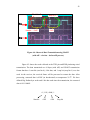
Figure 4.5 shows the result collected at the TXD pin and RXD pin during wired
transmission. The data transmitted are 44 bytes (with uIP) and USART transmission
format that have 1 start bit (star bit=0), 8 bit data, and 1 stop bit (stop bit=1) was also
used. At the receiver, the received frame will be processed to extract the data. After
processing, extracted data is 0X0F (in hexadecimal) at temperature 29 oC. We have
defined Big Endian byte order and 8 bit data each time the transmission, the extracted
data is 0111100001
0 | 1111 | 0000 | 1
Start bit
0XF
0X0
Stop bit
57
. The actual data is 0X0F which is 00001111.
Tx
Data = 0x0F (29 Celsius)
Stop bit = 1
Start bit = 0
Rx
Figure 4.5: Observed Data Transmission using USART
(with uIP – wireless – after uIP process)
58
4.2
Result at Hyper Terminal
Figure 4.6 shows the received data measured at RXD pin at 27 oC. Those data
were not extracted. There are 44 bytes data in a frame: 2 bytes header (link layer); 1 byte
checksum (link layer); 20 bytes TCP header; 20 bytes IP header; and 1 bite data. The
data were displayed in hexadecimal.
Data in a frame
44 bytes = 2 hdr
+ 1 cksm +
20 TCP header
+ 20 IP header
+ 1 data
Data = 0x0E
At 27 Celsius
Figure 4.6: Received Data Displayed at HyperTerminal.
(USART - with uIP – wireless – before uIP process)
Figure 4.7 shows the extracted data at HyperTerminal measured at TXD pin at
receiver node. All of those header were removed away to get the actual data. This data
was measured at temperature 27 oC.
59
Received data
in hex
(after uip process)
At 27 celsius
Figure 4.6: Received Data Displayed at HyperTerminal.
(USART - with uIP – wireless – after uIP process)
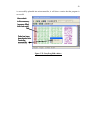
4.3
Result at Visual Basic 6.0 GUI
The transmitter node gets data from environment, and sends the frame after
processing. While at the receiver, the received frame was processed to retrieve the data.
After that, the extracted data was transmitted to the computer through the RS232 serial
cable in order to display the temperature value at the computer. So, the Graphical User
Interface (GUI) was developed for this purpose using Visual Basic 6.0
60
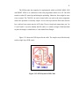
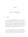
Figure 4.7 shows the GUI that developed to display the received temperature
value. The background wills change depends on the temperature value. If the
temperature is below than 30 oC, the background is green which is in normal condition.
When the temperature is in range 31 oC to 40 oC, the background is yellow shows that
now are hot condition. If the temperature is above 40 oC, the background is red meaning
very hot condition.
x < 30 degree (normal)
30< x < 41 degree (hot)
x > 40 degree ( very hot )
Figure 4.7: Graphical User Interface
CHAPTER 5
CONCLUSION AND RECOMMENDATION
5.1
Discussion
Due to many constraints and limited resources such as power consumption,
energy efficiency, available memory and buffering in the system that need to be
considered, implementing a TCP/IP protocol into the small architecture of an embedded
system seems to be a hard task. The source code that used to do the whole operations
was written in C language and were complied using WinAVR. The IP address and the
application port for transmitter node were configured to match with the receiver node. A
non-standard format was used to handle the data at the Link Layer. The verification of
data transmission was carried out for both wired and wireless communication.
In this thesis, the development of sensor nodes for both transmitter and receiver
part has been presented. Although the development of sensor nodes was done using a
small memory size of 8KB, the sensor nodes that can do sensing, processing and
networking using TCP/IP protocol have been successfully developed. As elaborated in
62
the previous chapter, the data transmission between the sensor nodes operated correctly
as developed in the programming sections.
5.2
Recommendation
The work carried out in this project were focused on the development of a sensor
node which constraint on sensing the temperature data, embedding the uIP stack into the
sensor node and testing the data transmission as well. But during the testing, no further
measurement was done to configure the delay, routing protocol, and medium access. The
suggestions for the future works are the following:
1. This project should be developed with smaller size, lower cost, but can be
used in wider application and functions since the development is carried out
without much constraint on the physical size and cost.
2. In addition, more sensor nodes should be further developed to represent a real
sensor and several sensor types can be combined to sense the data from
surroundings, depends on the sensor network application.
3. More analysis should be done in many angles such as in circuit design,
antenna design, measurement methodologies, and result representation.
REFERENCES
1. William Stallings (2004) “Data and Computer Communications” International
Edition: Seventh Edition, Upper Saddle River: NJ07458. Pearson Prentice Hall.
2. A. Dunkels (May 2003). Full TCP/IP for 8-bit architectures. In MOBISYS`03, San
Francisco, California. URL: http://dunkels.com/adam/uip
3. A. Dunkels (May 2003).”uIP-A Free Small TCP/IP Stack”. Technical paper.
4. A. Porret, T. Melly, C.C. Enz, E.A. Vittoz, A low-power low-voltage transceiver
architecture suitable for wireless distributed sensors network, IEEE International
Symposium on Circuits and Systems’00, Geneva, Vol. 1, 2000, pp.56–59.
5. G.J. Pottie, W.J. Kaiser, Wireless integrated network sensors, Communications of
the ACM 43 (5) (2000) 551–558.
6. A. Perrig, R. Szewczyk, V. Wen, D. Culler, J.D. Tygar, SPINS: security protocols
for sensor networks, Proceedings of ACM MobiCom’01, Rome, Italy, 2001, pp.
189– 199.
7. S. Hollar (2000). COTS Dust. Master Thesis, University of California, Berkeley.
64
8. Jones, M. Tim (2002). TCP/IP Application Layer Protocols for Embedded Systems.
Charles River Media, Inc.
9. A.
Dunkels,
The
Contiki
Operating
System.
Web
URL:http://www.sics.se/~adam/contiki
10. ATMEL corporation Website, URL: http://www.Atmel.com
11. GNU groups, AVR-GCC mailing list, URL:http://www.avrfreaks.com.
12. Jin Wook Lee (September 2002). Sensor Network and Technologies.
page.
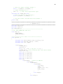
APPENDIX A
TRANSMITTER AND RECEIVER NODE SOURCE CODES
66
#######################################################################
##########################
#######################
/* TRANSMITTER NODE */
##########################
#######################
#######################################################################
#include "uip.h"
#include "rs232dev.h"
#include "app.h"
#include <stdio.h>
#include "compiler.h"
#include <avr/io.h>
#include "uip_arch.h"
#define TIMER_PRESCALE
1024
#define F_CPU
8000000
#define TIMERCOUNTER_PERIODIC_TIMEOUT (F_CPU / TIMER_PRESCALE / 2 /
256)
static unsigned char timerCounter;
void initTimer(void){
TCCR0=0x07;
TIMSK |=_BV(TOIE0);
timerCounter = 0;}
SIGNAL(SIG_OVERFLOW0){
timerCounter++;}
//***************** main *********************//
int main(void) {
int x;
rs232dev_init();
uip_init();
example1_init();
while(1){
uip_process(UIP_DATA);
*uip_appdata = adc();
rs232dev_send();
delay_1ms(1000);}
return 0;}
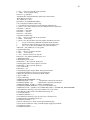
#####################################################################
/* USART TX */
#####################################################################
#include <avr/io.h>
#define FOSC 8000000// Clock Speed
#define BAUD 1200
#define baudrate (FOSC/16/BAUD-1)
unsigned int x;
unsigned int ADCL_data, ADCH_data;
//------------------ subrutin -----------------------void USART_Init(unsigned int UBRR){
/* Set baud rate */
UCSRA &= 0xfd;
UBRRH = (unsigned char)((UBRR)>>8);
UBRRL = (unsigned char)(UBRR);
/* Enable receiver and transmitter */
UCSRB = (1<<RXEN)|(1<<TXEN);
/* Set frame format: 8data, no parity, 1 stop bit */
UCSRC = (1<< URSEL) | (1<< UCSZ1) | (1<< UCSZ0);}
//to transmit 16 bits
void USART_Transmit(unsigned int x) {
/* Wait for empty transmit buffer */
67
while ( !(UCSRA & (1<<UDRE)) ) ;
/* Start transmission */
UDR = x; // send significant byte }
unsigned char USART_RX(void) {
/* Wait for data to be received */
while (!(UCSRA & (1<<RXC))) ;
/* Get and return received data from buffer */
return UDR;}
int adc (){
USART_Init(baudrate);
DDRA = 0x00; //set PORTA as input
PORTA = 0X00;
// Activate ADC with Prescaler 2
ADCSRA = 0b10000000 ;
ADMUX = 0b00100100;
ADCSRA |= 0B01000000;
while (ADCSRA & _BV(ADSC) ) {}
x = ADCH;
return x;}
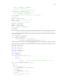
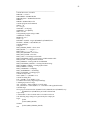
#######################################################################
/*A Very Simple Application" from the uIP 0.6 documentation*/
#######################################################################
#include "app.h"
void example1_init(void){
uip_listen(4500);}
void example1_app(void){
if(uip_newdata() || uip_rexmit()){
uip_send("okqqqqqqqqqqqqqqqqqqqq\n", 24);}}
#######################################################################
/* RS232_DEV */
#######################################################################
#include <avr/io.h>
#include <string.h>
#include <stdio.h>
#include <stdlib.h>
#include <ctype.h>
#include "rs232dev.h"
#include "uip.h"
char indata[];
char *indataptr;
void delay_1ms(unsigned int i){
char j;
while(i--)
{
j=11415;
// 8Mhz Exteranl Crystal(CKSEL3..0 = 1,1,1,1)
while(j--);}}
u8_t getchar_hextty_findnext(void) {
u8_t c;
char v;
while (*indataptr &&
!isalnum((int) (*indataptr))) {
indataptr++;}
if (*indataptr) {
v = *indataptr++;} else {
exit(0);}
if ((v >= '0')&&(v <= '9'))
c = v - '0';
68
else
c = toupper(v) - 'A' + 10;
return c;}
u8_t getchar_hextty(void) {
u8_t c;
c = getchar_hextty_findnext();
c = (c << 4) + getchar_hextty_findnext();
return c;}
#define SIO_RECV(c) c=getchar_hextty()
#define SIO_POLL(c) (c=getchar_hextty())
#define MAX_SIZE UIP_BUFSIZE
static u8_t slip_buf[MAX_SIZE];
#if MAX_SIZE > 255
static u16_t len, tmplen;
#else
static u8_t len, tmplen;
#endif /* MAX_SIZE > 255 */
/*-------------------------------------------------------------------*/
/*
* rs232dev_send():
*
* Sends the packet in the uip_buf and uip_appdata buffers. The first
* 40 bytes of the packet (the IP and TCP headers) are read from the
* uip_buf buffer, and the following bytes (the application data) are
* read from the uip_appdata buffer.
*/
/*-------------------------------------------------------------------*/
void rs232dev_send(void) {
#if MAX_SIZE > 255
u16_t i;
#else
u8_t i;
#endif /* MAX_SIZE > 255 */
u8_t *ptr;
u8_t c;
SIO_SEND('r');
SIO_SEND('z');
ptr = *uip_buf;
for(i = 0; i < 41/*uip_len*/; i++) {
if (i==13){
*ptr = UIP_IPADDR0;}
if (i==14){
*ptr = UIP_IPADDR1;}
if (i==15){
*ptr = UIP_IPADDR2;}
if (i==16){
*ptr = UIP_IPADDR3;}
if(i == 40) {
ptr = (u8_t*)uip_appdata;
c = *ptr;
PORTC=c;}
c = *ptr++;
SIO_SEND(c);}}
/*-------------------------------------------------------------------*/
/*
* rs232dev_init():
* Initializes the RS232 device and sets the parameters of the device.
69
*/
/*-------------------------------------------------------------------*/
void rs232dev_init(void) {
indataptr = indata;}
void SIO_SEND(unsigned char c) {
USART_Transmit(c);}
/*-------------------------------------------------------------------*/
#######################################################################
/* UIP STACK */
#######################################################################
#include <avr/io.h>
#include "uip.h"
#include "uipopt.h"
#include "uip_arch.h"
/*-------------------------------------------------------------------*/
/* Variable definitions. */
u8_t uip_buf[UIP_BUFSIZE];
/* The packet buffer that contains
incoming packets. */
volatile u8_t *uip_appdata; /* The uip_appdata pointer points to
application data. */
#if UIP_BUFSIZE > 255
volatile u16_t uip_len;
/* The uip_len is either 8 or 16 bits,
depending on the maximum packet size. */
#else
volatile u8_t uip_len;
#endif /* UIP_BUFSIZE > 255 */
volatile u8_t uip_flags;
/* The uip_flags variable is used for
communication between the TCP/IP stack
and the application program. */
struct uip_conn *uip_conn;
/* uip_conn always points to the current
connection. */
struct uip_conn uip_conns[UIP_CONNS];
/* The uip_conns array holds all TCP
connections. */
u16_t uip_listenports[UIP_LISTENPORTS];
/* The uip_listenports list all currently
listning ports. */
static u16_t ipid;
/* Ths ipid variable is an increasing
number that is used for the IP ID
field. */
static u8_t iss[4];
/* The iss variable is used for the TCP
initial sequence number. */
#if UIP_ACTIVE_OPEN
static u16_t lastport;
/* Keeps track of the last port used for
a new connection. */
#endif /* UIP_ACTIVE_OPEN */
/* Temporary variables. */
static u8_t c, opt;
static u16_t tmpport;
/* Structures and definitions. */
typedef struct {
/* IP header. */
u8_t vhl,
tos,
len[2],
ipid[2],
ipoffset[2],
70
ttl,
proto;
u16_t ipchksum;
u16_t srcipaddr[2],
destipaddr[2];
/* ICMP (echo) header. */
u8_t type, icode;
u16_t icmpchksum;
u16_t id, seqno;
} ipicmphdr;
#define TCP_FIN 0x01
#define TCP_SYN 0x02
#define TCP_RST 0x04
#define TCP_PSH 0x08
#define TCP_ACK 0x10
#define TCP_URG 0x20
#define IP_PROTO_ICMP
1
#define IP_PROTO_TCP
6
#define ICMP_ECHO_REPLY 0
#define ICMP_ECHO
8
/* Macros. */
#define BUF ((uip_tcpip_hdr *)&uip_buf[UIP_LLH_LEN])
#define ICMPBUF ((ipicmphdr *)&uip_buf[UIP_LLH_LEN])
#if UIP_STATISTICS == 1
struct uip_stats uip_stat;
#define UIP_STAT(s) s
#else
#define UIP_STAT(s)
#endif /* UIP_STATISTICS == 1 */
#if UIP_LOGGING == 1
#define UIP_LOG(m) printf("%s\n", m)
#else
#define UIP_LOG(m)
#endif /* UIP_LOGGING == 1 */
/*-------------------------------------------------------------------*/
void
uip_init(void){
for(c = 0; c < UIP_LISTENPORTS; ++c) {
uip_listenports[c] = 0;}
for(c = 0; c < UIP_CONNS; ++c) {
uip_conns[c].tcpstateflags = CLOSED;}
#if UIP_ACTIVE_OPEN
lastport = 1024;
#endif /* UIP_ACTIVE_OPEN */}
/*-------------------------------------------------------------------*/
#if UIP_ACTIVE_OPEN
struct uip_conn *
uip_connect(u16_t *ripaddr, u16_t rport){
struct uip_conn *conn;
/* Find an unused local port. */
again:
++lastport;
if(lastport >= 32000) {
lastport = 4096;}
for(c = 0; c < UIP_CONNS; ++c) {
if(uip_conns[c].tcpstateflags != CLOSED &&
uip_conns[c].lport == lastport)
71
goto again;}
for(c = 0; c < UIP_CONNS; ++c) {
if(uip_conns[c].tcpstateflags == CLOSED)
goto found_unused;}
for(c = 0; c < UIP_CONNS; ++c) {
if(uip_conns[c].tcpstateflags == TIME_WAIT)
goto found_unused;}
return (void *)0;
found_unused:
conn = &uip_conns[c];
conn->tcpstateflags = SYN_SENT | UIP_OUTSTANDING;
conn->snd_nxt[0] = conn->ack_nxt[0] = iss[0];
conn->snd_nxt[1] = conn->ack_nxt[1] = iss[1];
conn->snd_nxt[2] = conn->ack_nxt[2] = iss[2];
conn->snd_nxt[3] = conn->ack_nxt[3] = iss[3];
if(++conn->ack_nxt[3] == 0) {
if(++conn->ack_nxt[2] == 0) {
if(++conn->ack_nxt[1] == 0) {
++conn->ack_nxt[0];
}
}
}
conn->nrtx = 0;
conn->timer = 1; /* Send the SYN next time around. */
conn->lport = htons(lastport);
conn->rport = htons(rport);
conn->ripaddr[0] = ripaddr[0];
conn->ripaddr[1] = ripaddr[1];
return conn;}
#endif /* UIP_ACTIVE_OPEN */
/*-------------------------------------------------------------------*/
void
uip_listen(u16_t port){
for(c = 0; c < UIP_LISTENPORTS; ++c) {
if(uip_listenports[c] == 0) {
uip_listenports[c] = htons(port);
break;
}
}
}
/*-------------------------------------------------------------------*/
void
uip_process(u8_t flag){
uip_appdata = &uip_buf[40 + UIP_LLH_LEN];
/* Check if we were invoked because of the perodic timer fireing. */
if(flag == UIP_TIMER) {
/* Increase the initial sequence number. */
if(++iss[3] == 0) {
if(++iss[2] == 0) {
if(++iss[1] == 0) {
++iss[0];}
}
}
uip_len = 0;
if(uip_conn->tcpstateflags == TIME_WAIT ||
uip_conn->tcpstateflags == FIN_WAIT_2) {
++(uip_conn->timer);
72
if(uip_conn->timer == UIP_TIME_WAIT_TIMEOUT) {
uip_conn->tcpstateflags = CLOSED;}
} else if(uip_conn->tcpstateflags != CLOSED) {
/* If the connection has outstanding data, we increase the
connection's timer and see if it has reached the RTO value
in which case we retransmit. */
if(uip_conn->tcpstateflags & UIP_OUTSTANDING) {
--(uip_conn->timer);
if(uip_conn->timer == 0) {
if(uip_conn->nrtx == UIP_MAXRTX) {
uip_conn->tcpstateflags = CLOSED;
/* We call UIP_APPCALL() with uip_flags set to
UIP_TIMEDOUT to inform the application that the
connection has timed out. */
uip_flags = UIP_TIMEDOUT;
UIP_APPCALL();
/* We also send a reset packet to the remote host. */
BUF->flags = TCP_RST | TCP_ACK;
goto tcp_send_nodata;
}
/* Exponential backoff. */
uip_conn->timer = UIP_RTO << (uip_conn->nrtx > 4? 4: uip_conn>nrtx);
++(uip_conn->nrtx);
/* Ok, so we need to retransmit. We do this differently
depending on which state we are in. In ESTABLISHED, we
call upon the application so that it may prepare the
data for the retransmit. In SYN_RCVD, we resend the
SYNACK that we sent earlier and in LAST_ACK we have to
retransmit our FINACK. */
UIP_STAT(++uip_stat.tcp.rexmit);
switch(uip_conn->tcpstateflags & TS_MASK) {
case SYN_RCVD:
/* In the SYN_RCVD state, we should retransmit our
SYNACK. */
goto tcp_send_synack;
#if UIP_ACTIVE_OPEN
case SYN_SENT:
/* In the SYN_SENT state, we retransmit out SYN. */
BUF->flags = 0;
goto tcp_send_syn;
#endif /* UIP_ACTIVE_OPEN */
case ESTABLISHED:
/* In the ESTABLISHED state, we call upon the application
to do the actual retransmit after which we jump into
the code for sending out the packet (the apprexmit
label). */
uip_len = 0;
uip_flags = UIP_REXMIT;
UIP_APPCALL();
goto apprexmit;
case FIN_WAIT_1:
case CLOSING:
73
case LAST_ACK:
/* In all these states we should retransmit a FINACK. */
goto tcp_send_finack;
}
}
} else if((uip_conn->tcpstateflags & TS_MASK) == ESTABLISHED) {
/* If there was no need for a retransmission, we poll the
application for new data. */
uip_len = 0;
uip_flags = UIP_POLL;
UIP_APPCALL();
goto appsend;
}
}
goto drop;
}
/* This is where the input processing starts. */
UIP_STAT(++uip_stat.ip.recv);
/* Check validity of the IP header. */
if(BUF->vhl != 0x45) { /* IP version and header length. */
UIP_STAT(++uip_stat.ip.drop);
UIP_STAT(++uip_stat.ip.vhlerr);
UIP_LOG("ip: invalid version or header length.");
goto drop;
}
/* Check the size of the packet. If the size reported to us in
uip_len doesn't match the size reported in the IP header, there
has been a transmission error and we drop the packet. */
#if UIP_BUFSIZE > 255
if(BUF->len[0] != ((uip_len - UIP_LLH_LEN) >> 8)) {
UIP_STAT(++uip_stat.ip.drop);
UIP_STAT(++uip_stat.ip.hblenerr);
UIP_LOG("ip: invalid length, high byte.");
/* IP length, high byte. */
goto drop;
}
if(BUF->len[1] != ((uip_len - UIP_LLH_LEN) & 0xff)) {
UIP_STAT(++uip_stat.ip.drop);
UIP_STAT(++uip_stat.ip.lblenerr);
UIP_LOG("ip: invalid length, low byte.");
/* IP length, low byte. */
goto drop;
}
#else
if(BUF->len[0] != 0) {
/* IP length, high byte. */
UIP_STAT(++uip_stat.ip.drop);
UIP_STAT(++uip_stat.ip.hblenerr);
UIP_LOG("ip: invalid length, high byte.");
goto drop;}
if(BUF->len[1] != (uip_len - UIP_LLH_LEN)) { /* IP length, low byte.
*/
UIP_STAT(++uip_stat.ip.drop);
UIP_STAT(++uip_stat.ip.lblenerr);
UIP_LOG("ip: invalid length, low byte.");
goto drop;}
#endif /* UIP_BUFSIZE > 255 */
if(BUF->ipoffset[0] & 0x3f) { /* We don't allow IP fragments. */
74
UIP_STAT(++uip_stat.ip.drop);
UIP_STAT(++uip_stat.ip.fragerr);
UIP_LOG("ip: fragment dropped.");
goto drop;}
/* Check if the packet is destined for our IP address. */
if(BUF->destipaddr[0] != htons(((u16_t)UIP_IPADDR0 << 8) |
UIP_IPADDR1)) {
UIP_STAT(++uip_stat.ip.drop);
UIP_LOG("ip: packet not for us.");
goto drop;}
if(BUF->destipaddr[1] != htons(((u16_t)UIP_IPADDR2 << 8) |
UIP_IPADDR3)) {
UIP_STAT(++uip_stat.ip.drop);
UIP_LOG("ip: packet not for us.");
goto drop;}
if(uip_ipchksum() != 0xffff) { /* Compute and check the IP header
checksum. */
UIP_STAT(++uip_stat.ip.drop);
UIP_STAT(++uip_stat.ip.chkerr);
UIP_LOG("ip: bad checksum.");
goto drop;}
if(BUF->proto == IP_PROTO_TCP) /* Check for TCP packet. If so, jump
to the tcp_input label. */
goto tcp_input;
if(BUF->proto != IP_PROTO_ICMP) { /* We only allow ICMP packets from
here. */
UIP_STAT(++uip_stat.ip.drop);
UIP_STAT(++uip_stat.ip.protoerr);
UIP_LOG("ip: neither tcp nor icmp.");
goto drop;}
UIP_STAT(++uip_stat.icmp.recv);
/* ICMP echo (i.e., ping) processing. This is simple, we only change
the ICMP type from ECHO to ECHO_REPLY and adjust the ICMP
checksum before we return the packet. */
if(ICMPBUF->type != ICMP_ECHO) {
UIP_STAT(++uip_stat.icmp.drop);
UIP_STAT(++uip_stat.icmp.typeerr);
UIP_LOG("icmp: not icmp echo.");
goto drop;}
ICMPBUF->type = ICMP_ECHO_REPLY;
if(ICMPBUF->icmpchksum >= htons(0xffff - (ICMP_ECHO << 8))) {
ICMPBUF->icmpchksum += htons(ICMP_ECHO << 8) + 1;
} else {
ICMPBUF->icmpchksum += htons(ICMP_ECHO << 8);}
/* Swap IP addresses. */
tmpport = BUF->destipaddr[0];
BUF->destipaddr[0] = BUF->srcipaddr[0];
BUF->srcipaddr[0] = tmpport;
tmpport = BUF->destipaddr[1];
BUF->destipaddr[1] = BUF->srcipaddr[1];
BUF->srcipaddr[1] = tmpport;
UIP_STAT(++uip_stat.icmp.sent);
goto send;
/* TCP input processing. */
tcp_input:
UIP_STAT(++uip_stat.tcp.recv);
if(uip_tcpchksum() != 0xffff) {
/* Compute and check the TCP
75
checksum. */
UIP_STAT(++uip_stat.tcp.drop);
UIP_STAT(++uip_stat.tcp.chkerr);
UIP_LOG("tcp: bad checksum.");
goto drop;}
/* Demultiplex this segment. */
/* First check any active connections. */
for(uip_conn = &uip_conns[0]; uip_conn < &uip_conns[UIP_CONNS];
++uip_conn) {
if(uip_conn->tcpstateflags != CLOSED &&
BUF->srcipaddr[0] == uip_conn->ripaddr[0] &&
BUF->srcipaddr[1] == uip_conn->ripaddr[1] &&
BUF->destport == uip_conn->lport &&
BUF->srcport == uip_conn->rport)
goto found;
}
/* If we didn't find and active connection that expected the packet,
either this packet is an old duplicate, or this is a SYN packet
destined for a connection in LISTEN. If the SYN flag isn't set,
it is an old packet and we send a RST. */
if(BUF->flags != TCP_SYN)
goto reset;
tmpport = BUF->destport;
/* Next, check listening connections. */
for(c = 0; c < UIP_LISTENPORTS && uip_listenports[c] != 0; ++c) {
if(tmpport == uip_listenports[c])
goto found_listen;}
/* No matching connection found, so we send a RST packet. */
UIP_STAT(++uip_stat.tcp.synrst);
reset:
/* We do not send resets in response to resets. */
if(BUF->flags & TCP_RST)
goto drop;
UIP_STAT(++uip_stat.tcp.rst);
BUF->flags = TCP_RST | TCP_ACK;
uip_len = 40;
BUF->tcpoffset = 5 << 4;
/* Flip the seqno and ackno fields in the TCP header. */
c = BUF->seqno[3];
BUF->seqno[3] = BUF->ackno[3];
BUF->ackno[3] = c;
c = BUF->seqno[2];
BUF->seqno[2] = BUF->ackno[2];
BUF->ackno[2] = c;
c = BUF->seqno[1];
BUF->seqno[1] = BUF->ackno[1];
BUF->ackno[1] = c;
c = BUF->seqno[0];
BUF->seqno[0] = BUF->ackno[0];
BUF->ackno[0] = c;
/* We also have to increase the sequence number we are
acknowledging. If the least significant byte overflowed, we need
to propagate the carry to the other bytes as well. */
if(++BUF->ackno[3] == 0) {
if(++BUF->ackno[2] == 0) {
if(++BUF->ackno[1] == 0) {
++BUF->ackno[0];}}
}
76
/* Swap port numbers. */
tmpport = BUF->srcport;
BUF->srcport = BUF->destport;
BUF->destport = tmpport;
/* Swap IP addresses. */
tmpport = BUF->destipaddr[0];
BUF->destipaddr[0] = BUF->srcipaddr[0];
BUF->srcipaddr[0] = tmpport;
tmpport = BUF->destipaddr[1];
BUF->destipaddr[1] = BUF->srcipaddr[1];
BUF->srcipaddr[1] = tmpport;
/* And send out the RST packet! */
goto tcp_send_noconn;
/* This label will be jumped to if we matched the incoming packet
with a connection in LISTEN. In that case, we should create a new
connection and send a SYNACK in return. */
found_listen:
/* First we check if there are any connections avaliable. Unused
connections are kept in the same table as used connections, but
unused ones have the tcpstate set to CLOSED. */
for(c = 0; c < UIP_CONNS; ++c) {
if(uip_conns[c].tcpstateflags == CLOSED)
goto found_unused_connection;}
for(c = 0; c < UIP_CONNS; ++c) {
if(uip_conns[c].tcpstateflags == TIME_WAIT)
goto found_unused_connection;}
/* All connections are used already, we drop packet and hope that
the remote end will retransmit the packet at a time when we have
more spare connections. */
UIP_STAT(++uip_stat.tcp.syndrop);
UIP_LOG("tcp: found no unused connections.");
goto drop;
/* This label will be jumped to if we have found an unused
connection that we can use. */
found_unused_connection:
uip_conn = &uip_conns[c];
/* Fill in the necessary fields for the new connection. */
uip_conn->timer = UIP_RTO;
uip_conn->nrtx = 0;
uip_conn->lport = BUF->destport;
uip_conn->rport = BUF->srcport;
uip_conn->ripaddr[0] = BUF->srcipaddr[0];
uip_conn->ripaddr[1] = BUF->srcipaddr[1];
uip_conn->tcpstateflags = SYN_RCVD | UIP_OUTSTANDING;
uip_conn->snd_nxt[0] = uip_conn->ack_nxt[0] = iss[0];
uip_conn->snd_nxt[1] = uip_conn->ack_nxt[1] = iss[1];
uip_conn->snd_nxt[2] = uip_conn->ack_nxt[2] = iss[2];
uip_conn->snd_nxt[3] = uip_conn->ack_nxt[3] = iss[3];
uip_add_ack_nxt(1);
/* rcv_nxt should be the seqno from the incoming packet + 1. */
uip_conn->rcv_nxt[3] = BUF->seqno[3];
uip_conn->rcv_nxt[2] = BUF->seqno[2];
uip_conn->rcv_nxt[1] = BUF->seqno[1];
uip_conn->rcv_nxt[0] = BUF->seqno[0];
uip_add_rcv_nxt(1);
/* Parse the TCP MSS option, if present. */
if((BUF->tcpoffset & 0xf0) > 0x50) {
77
for(c = 0; c < ((BUF->tcpoffset >> 4) - 5) << 2 ;) {
opt = uip_buf[40 + UIP_LLH_LEN + c];
if(opt == 0x00) {
/* End of options. */
break;
} else if(opt == 0x01) {
++c;
/* NOP option. */
} else if(opt == 0x02 &&
uip_buf[40 + UIP_LLH_LEN + c + 1] == 0x04) {
/* An MSS option with the right option length. */
tmpport = (uip_buf[40 + UIP_LLH_LEN + c + 2] << 8) |
uip_buf[40 + UIP_LLH_LEN + c + 3];
uip_conn->mss = tmpport > UIP_TCP_MSS? UIP_TCP_MSS: tmpport;
/* And we are done processing options. */
break;
} else {
/* All other options have a length field, so that we easily
can skip past them. */
c += uip_buf[40 + UIP_LLH_LEN + c + 1];
}
}
}
/* Our response will be a SYNACK. */
#if UIP_ACTIVE_OPEN
tcp_send_synack:
BUF->flags = TCP_ACK;
tcp_send_syn:
BUF->flags |= TCP_SYN;
#else /* UIP_ACTIVE_OPEN */
tcp_send_synack:
BUF->flags = TCP_SYN | TCP_ACK;
#endif /* UIP_ACTIVE_OPEN */
/* We send out the TCP Maximum Segment Size option with our
SYNACK. */
BUF->optdata[0] = 2;
BUF->optdata[1] = 4;
BUF->optdata[2] = (UIP_TCP_MSS) / 256;
BUF->optdata[3] = (UIP_TCP_MSS) & 255;
uip_len = 44;
BUF->tcpoffset = 6 << 4;
goto tcp_send;
/* This label will be jumped to if we found an active connection. */
found:
uip_flags = 0;
/* We do a very naive form of TCP reset processing; we just accept
any RST and kill our connection. We should in fact check if the
sequence number of this reset is wihtin our advertised window
before we accept the reset. */
if(BUF->flags & TCP_RST) {
uip_conn->tcpstateflags = CLOSED;
UIP_LOG("tcp: got reset, aborting connection.");
uip_flags = UIP_ABORT;
UIP_APPCALL();
goto drop;}
/* All segments that are come thus far should have the ACK flag set,
78
otherwise we drop the packet. */
if(!(BUF->flags & TCP_ACK)) {
UIP_STAT(++uip_stat.tcp.drop);
UIP_STAT(++uip_stat.tcp.ackerr);
UIP_LOG("tcp: dropped non-ack segment.");
goto drop;}
/* Calculated the length of the data, if the application has sent
any data to us. */
c = (BUF->tcpoffset >> 4) << 2;
/* uip_len will contain the length of the actual TCP data. This is
calculated by subtracing the length of the TCP header (in
c) and the length of the IP header (20 bytes). */
uip_len = uip_len - c - 20;
/* First, check if the sequence number of the incoming packet is
what we're expecting next. If not, we send out an ACK with the
correct numbers in. */
if(uip_len > 0 &&
(BUF->seqno[0] != uip_conn->rcv_nxt[0] ||
BUF->seqno[1] != uip_conn->rcv_nxt[1] ||
BUF->seqno[2] != uip_conn->rcv_nxt[2] ||
BUF->seqno[3] != uip_conn->rcv_nxt[3])) {
goto tcp_send_ack;}
/* Next, check if the incoming segment acknowledges any outstanding
data. If so, we also reset the retransmission timer. */
if(BUF->ackno[0] == uip_conn->ack_nxt[0] &&
BUF->ackno[1] == uip_conn->ack_nxt[1] &&
BUF->ackno[2] == uip_conn->ack_nxt[2] &&
BUF->ackno[3] == uip_conn->ack_nxt[3]) {
uip_conn->snd_nxt[0] = uip_conn->ack_nxt[0];
uip_conn->snd_nxt[1] = uip_conn->ack_nxt[1];
uip_conn->snd_nxt[2] = uip_conn->ack_nxt[2];
uip_conn->snd_nxt[3] = uip_conn->ack_nxt[3];
if(uip_conn->tcpstateflags & UIP_OUTSTANDING) {
uip_flags = UIP_ACKDATA;
uip_conn->tcpstateflags &= ~UIP_OUTSTANDING;
uip_conn->timer = UIP_RTO;
}
}
/* Do different things depending on in what state the connection is.
*/
switch(uip_conn->tcpstateflags & TS_MASK) {
/* CLOSED and LISTEN are not handled here. CLOSE_WAIT is not
implemented, since we force the application to close when the
peer sends a FIN (hence the application goes directly from
ESTABLISHED to LAST_ACK). */
case SYN_RCVD:
/* In SYN_RCVD we have sent out a SYNACK in response to a SYN, and
we are waiting for an ACK that acknowledges the data we sent
out the last time. Therefore, we want to have the UIP_ACKDATA
flag set. If so, we enter the ESTABLISHED state. */
if(uip_flags & UIP_ACKDATA) {
uip_conn->tcpstateflags = ESTABLISHED;
uip_flags = UIP_CONNECTED;
uip_len = 0;
UIP_APPCALL();
goto appsend;
}
79
goto drop;
#if UIP_ACTIVE_OPEN
case SYN_SENT:
/* In SYN_SENT, we wait for a SYNACK that is sent in response to
our SYN. The rcv_nxt is set to sequence number in the SYNACK
plus one, and we send an ACK. We move into the ESTABLISHED
state. */
if((uip_flags & UIP_ACKDATA) &&
BUF->flags == (TCP_SYN | TCP_ACK)) {
/* Parse the TCP MSS option, if present. */
if((BUF->tcpoffset & 0xf0) > 0x50) {
for(c = 0; c < ((BUF->tcpoffset >> 4) - 5) << 2 ;) {
opt = uip_buf[40 + UIP_LLH_LEN + c];
if(opt == 0x00) {
/* End of options. */
break;
} else if(opt == 0x01) {
++c;
/* NOP option. */
} else if(opt == 0x02 &&
uip_buf[40 + UIP_LLH_LEN + c + 1] == 0x04) {
/* An MSS option with the right option length. */
tmpport = (uip_buf[40 + UIP_LLH_LEN + c + 2] << 8) |
uip_buf[40 + UIP_LLH_LEN + c + 3];
uip_conn->mss = tmpport > UIP_TCP_MSS? UIP_TCP_MSS: tmpport;
/* And we are done processing options. */
break;
} else {
/* All other options have a length field, so that we easily
can skip past them. */
c += uip_buf[40 + UIP_LLH_LEN + c + 1];
}
}
}
uip_conn->tcpstateflags = ESTABLISHED;
uip_conn->rcv_nxt[0] = BUF->seqno[0];
uip_conn->rcv_nxt[1] = BUF->seqno[1];
uip_conn->rcv_nxt[2] = BUF->seqno[2];
uip_conn->rcv_nxt[3] = BUF->seqno[3];
uip_add_rcv_nxt(1);
uip_flags = UIP_CONNECTED | UIP_NEWDATA;
uip_len = 0;
UIP_APPCALL();
goto appsend;}
goto drop;
#endif /* UIP_ACTIVE_OPEN */
case ESTABLISHED:
if(BUF->flags & TCP_FIN) {
uip_add_rcv_nxt(1 + uip_len);
uip_flags = UIP_CLOSE;
uip_len = 0;
UIP_APPCALL();
uip_add_ack_nxt(1);
uip_conn->tcpstateflags = LAST_ACK | UIP_OUTSTANDING;
uip_conn->nrtx = 0;
tcp_send_finack:
BUF->flags = TCP_FIN | TCP_ACK;
80
goto tcp_send_nodata;}
/* If uip_len > 0 we have TCP data in the packet, and we flag this
by setting the UIP_NEWDATA flag and update the sequence number
we acknowledge. If the application has stopped the dataflow
using uip_stop(), we must not accept any data packets from the
remote host. */
if(uip_len > 0 && !(uip_conn->tcpstateflags & UIP_STOPPED)) {
uip_flags |= UIP_NEWDATA;
uip_add_rcv_nxt(uip_len);}
if(uip_flags & (UIP_NEWDATA | UIP_ACKDATA)) {
UIP_APPCALL();
appsend:
if(uip_flags & UIP_ABORT) {
uip_conn->tcpstateflags = CLOSED;
BUF->flags = TCP_RST | TCP_ACK;
goto tcp_send_nodata;
}
if(uip_flags & UIP_CLOSE) {
uip_add_ack_nxt(1);
uip_conn->tcpstateflags = FIN_WAIT_1 | UIP_OUTSTANDING;
uip_conn->nrtx = 0;
BUF->flags = TCP_FIN | TCP_ACK;
goto tcp_send_nodata;
}
/* If uip_len > 0, the application has data to be sent, in which
case we set the UIP_OUTSTANDING flag in the connection
structure. But we cannot send data if the application already
has outstanding data. */
if(uip_len > 0 &&
!(uip_conn->tcpstateflags & UIP_OUTSTANDING)) {
uip_conn->tcpstateflags |= UIP_OUTSTANDING;
uip_conn->nrtx = 0;
uip_add_ack_nxt(uip_len);
} else {
uip_len = 0;
}
apprexmit:
/* If the application has data to be sent, or if the incoming
packet had new data in it, we must send out a packet. */
if(uip_len > 0 || (uip_flags & UIP_NEWDATA)) {
/* Add the length of the IP and TCP headers. */
uip_len = uip_len + 40;
/* We always set the ACK flag in response packets. */
BUF->flags = TCP_ACK;
/* Send the packet. */
goto tcp_send_noopts;
}}
goto drop;
case LAST_ACK:
/* We can close this connection if the peer has acknowledged our
FIN. This is indicated by the UIP_ACKDATA flag. */
if(uip_flags & UIP_ACKDATA) {
uip_conn->tcpstateflags = CLOSED;
}
break;
case FIN_WAIT_1:
/* The application has closed the connection, but the remote host
81
hasn't closed its end yet. Thus we do nothing but wait for a
FIN from the other side. */
if(uip_len > 0) {
uip_add_rcv_nxt(uip_len);}
if(BUF->flags & TCP_FIN) {
if(uip_flags & UIP_ACKDATA) {
uip_conn->tcpstateflags = TIME_WAIT;
uip_conn->timer = 0;
} else {
uip_conn->tcpstateflags = CLOSING | UIP_OUTSTANDING;
}
uip_add_rcv_nxt(1);
goto tcp_send_ack;
} else if(uip_flags & UIP_ACKDATA) {
uip_conn->tcpstateflags = FIN_WAIT_2;
goto drop;}
if(uip_len > 0) {
goto tcp_send_ack;}
goto drop;
case FIN_WAIT_2:
if(uip_len > 0) {
uip_add_rcv_nxt(uip_len);}
if(BUF->flags & TCP_FIN) {
uip_conn->tcpstateflags = TIME_WAIT;
uip_conn->timer = 0;
uip_add_rcv_nxt(1);
goto tcp_send_ack;}
if(uip_len > 0) {
goto tcp_send_ack;}
goto drop;
case TIME_WAIT:
goto tcp_send_ack;
case CLOSING:
if(uip_flags & UIP_ACKDATA) {
uip_conn->tcpstateflags = TIME_WAIT;
uip_conn->timer = 0;
}}
goto drop;
/* We jump here when we are ready to send the packet, and just want
to set the appropriate TCP sequence numbers in the TCP header. */
tcp_send_ack:
BUF->flags = TCP_ACK;
tcp_send_nodata:
uip_len = 40;
tcp_send_noopts:
BUF->tcpoffset = 5 << 4;
tcp_send:
/* We're done with the input processing. We are now ready to send a
reply. Our job is to fill in all the fields of the TCP and IP
headers before calculating the checksum and finally send the
packet. */
BUF->ackno[0] = uip_conn->rcv_nxt[0];
BUF->ackno[1] = uip_conn->rcv_nxt[1];
BUF->ackno[2] = uip_conn->rcv_nxt[2];
BUF->ackno[3] = uip_conn->rcv_nxt[3];
BUF->seqno[0] = uip_conn->snd_nxt[0];
BUF->seqno[1] = uip_conn->snd_nxt[1];
82
BUF->seqno[2] = uip_conn->snd_nxt[2];
BUF->seqno[3] = uip_conn->snd_nxt[3];
BUF->srcport = uip_conn->lport;
BUF->destport = uip_conn->rport;
//#if BYTE_ORDER == BIG_ENDIAN
BUF->srcipaddr[0] = 1002; // ((UIP_IPADDR0 << 8) | UIP_IPADDR1);
BUF->srcipaddr[1] = 0010; // ((UIP_IPADDR2 << 8) | UIP_IPADDR3);
//#else
//BUF->srcipaddr[0] = ((UIP_IPADDR1 << 8) | UIP_IPADDR0);
//BUF->srcipaddr[1] = ((UIP_IPADDR3 << 8) | UIP_IPADDR2);
//#endif /* BYTE_ORDER == BIG_ENDIAN */
BUF->destipaddr[0] = uip_conn->ripaddr[0];
BUF->destipaddr[1] = uip_conn->ripaddr[1];
if(uip_conn->tcpstateflags & UIP_STOPPED) {
/* If the connection has issued uip_stop(), we advertise a zero
window so that the remote host will stop sending data. */
BUF->wnd[0] = BUF->wnd[1] = 0;
} else {
#if (UIP_TCP_MSS) > 255
BUF->wnd[0] = (uip_conn->mss >> 8);
#else
BUF->wnd[0] = 0;
#endif /* UIP_MSS */
BUF->wnd[1] = (uip_conn->mss & 0xff);
}
tcp_send_noconn:
BUF->vhl = 0x45;
BUF->tos = 0;
BUF->ipoffset[0] = BUF->ipoffset[1] = 0;
BUF->ttl = UIP_TTL;
BUF->proto = IP_PROTO_TCP;
#if UIP_BUFSIZE > 255
BUF->len[0] = (uip_len >> 8);
BUF->len[1] = (uip_len & 0xff);
#else
BUF->len[0] = 0;
BUF->len[1] = uip_len;
#endif /* UIP_BUFSIZE > 255 */
++ipid;
BUF->ipid[0] = ipid >> 8;
BUF->ipid[1] = ipid & 0xff;
/* Calculate IP and TCP checksums. */
BUF->ipchksum = 0;
BUF->ipchksum = ~(uip_ipchksum());
BUF->tcpchksum = 0;
BUF->tcpchksum = ~(uip_tcpchksum());
UIP_STAT(++uip_stat.tcp.sent);
send:
UIP_STAT(++uip_stat.ip.sent);
/* The data that should be sent is not present in the uip_buf, and
the length of the data is in the variable uip_len. It is not our
responsibility to do the actual sending of the data however. That
is taken care of by the wrapper code, and only if uip_len > 0. */
return;
drop:
uip_len = 0;
return;}
83
/*-------------------------------------------------------------------*/
#####################################################################
/* UIPOPT.H */
#####################################################################
/*
* Copyright (c) 2001, Adam Dunkels.
* This file is part of the uIP TCP/IP stack.
*
* $Id: uipopt.h,v 1.5 2002/01/13 21:12:41 adam Exp $
*
*/
#ifndef __UIPOPT_H__
#define __UIPOPT_H__
/* This file is used for tweaking various configuration options for
uIP. You should make a copy of this file into one of your project's
directories instead of editing this example "uipopt.h" file that
comes with the uIP distribution. */
/*-------------------------------------------------------------------*/
/* First, two typedefs that may have to be tweaked for your particular
compiler. The uX_t types are unsigned integer types, where the X is
the number of bits in the integer type. Most compilers use
"unsigned char" and "unsigned short" for those two,
respectively. */
typedef unsigned char u8_t;
typedef unsigned short u16_t;
/*-------------------------------------------------------------------*/
/* The configuration options for a specific node. This includes IP
* address, netmask and default router as well as the Ethernet
* address. The netmask, default router and Ethernet address are
* appliciable only if uIP should be run over Ethernet.
* All of these should be changed to suit your project.
*/
/* UIP_IPADDR: The IP address of this uIP node. */
#define UIP_IPADDR0
0x0A //10
#define UIP_IPADDR1
0X02 //2
#define UIP_IPADDR2
0X00 //0
#define UIP_IPADDR3
0X0A //10
/*-------------------------------------------------------------------*/
#include "app.h"
/* UIP_ACTIVE_OPEN: Determines if support for opening connections from
uIP should be compiled in. If this isn't needed for your
application, don't turn it on. (A web server doesn't need this, for
instance.) */
#define UIP_ACTIVE_OPEN 1
/* UIP_CONNS: The maximum number of simultaneously active
connections. */
#define UIP_CONNS
10
/* UIP_LISTENPORTS: The maximum number of simultaneously listening TCP
ports. For a web server, 1 is enough here. */
#define UIP_LISTENPORTS 10
/* UIP_BUFSIZE: The size of the buffer that holds incoming and
outgoing packets. */
#d
/* UIP_STATISTICS: Determines if statistics support should be compiled
in. The statistics is useful for debugging and to show the user. */
#define UIP_STATISTICS 0
/* UIP_LOGGING: Determines if logging of certain events should be
84
compiled in. Useful mostly for debugging. The function uip_log(char
*msg) must be implemented to suit your architecture if logging is
turned on. */
#define UIP_LOGGING
0
/* UIP_LLH_LEN: The link level header length; this is the offset into
the uip_buf where the IP header can be found. For Ethernet, this
should be set to 14. For SLIP, this should be set to 0. */
#define UIP_LLH_LEN
0
/*-------------------------------------------------------------------*/
/* The following configuration options can be tweaked for your
* project, but you are probably safe to use the default values. The
* options are listed in order of tweakability.
*/
/* UIP_ARPTAB_SIZE: The size of the ARP table - use a larger value if
this uIP node will have many connections from the local network. */
#define UIP_ARPTAB_SIZE 8
/* The maxium age of ARP table entries measured in 10ths of
seconds. An UIP_ARP_MAXAGE of 120 corresponds to 20 minutes (BSD
default). */
#define UIP_ARP_MAXAGE 120
/* UIP_RTO: The retransmission timeout counted in timer pulses (i.e.,
the speed of the periodic timer, usually one second). */
#define UIP_RTO
3
/* UIP_MAXRTX: The maximum number of times a segment should be
retransmitted before the connection should be aborted. */
#define UIP_MAXRTX
8
/* UIP_TCP_MSS: The TCP maximum segment size. This should be set to
at most UIP_BUFSIZE - UIP_LLH_LEN - 40. */
#define UIP_TCP_MSS
(UIP_BUFSIZE - UIP_LLH_LEN - 40)
/* UIP_TTL: The IP TTL (time to live) of IP packets sent by uIP. */
#define UIP_TTL
255
/* UIP_TIME_WAIT_TIMEOUT: How long a connection should stay in the
TIME_WAIT state. Has no real implication, so it should be left
untouched. */
#define UIP_TIME_WAIT_TIMEOUT 120
/*-------------------------------------------------------------------*/
#ifndef LITTLE_ENDIAN
#define LITTLE_ENDIAN 3412
#endif /* LITTLE_ENDIAN */
#ifndef BIG_ENDIAN
#define BIG_ENDIAN
1234
#endif /* BIGE_ENDIAN */
// SPARC IS BIG_ENDIAN, INTEL IS LITTLE_ENDIAN
#ifndef BYTE_ORDER
#define BYTE_ORDER
BIG_ENDIAN
#endif /* BYTE_ORDER */
#endif /* __UIPOPT_H__ */
#######################################################################
##########################
#######################
/* RECEIVER NODE */
##########################
#######################
#######################################################################
#include <avr/io.h>
#include <stdio.h>
#define TIMER_PRESCALE
1024
#define F_CPU
8000000
//************** main *****************//
85
int main ()
{
int c;
DDRC=0XFF;
PORTC=0X00;
while(1){
c=USART_RX();
process();
}
return 0;
}
#######################################################################
/* DELAY */
#######################################################################
#include <avr/io.h>
typedef unsigned char byte;
typedef unsigned int word;
// 1msec UNIT delay function
void delay_ms(unsigned int i)
{
word j;
while(i--)
{
j=11415;
// 8Mhz Exteranl Crystal(CKSEL3..0 = 1,1,1,1)
while(j--);
}
}
#######################################################################
/* USART RX */
#######################################################################
#include <avr/io.h>
#define FOSC 8000000// Clock Speed
#define BAUD 1200
#define baudrate (FOSC/16/BAUD-1)
void USART_TX(unsigned char x);
void USART_Init(unsigned int UBRR);
unsigned char USART_RX(void);
void hexASCII(unsigned char cr);
unsigned int X,y,i,cr,a,data;
void usart (void) {
USART_Init(baudrate);
}
void USART_Init(unsigned int UBRR)
{
/* Set baud rate */
UBRRH = (unsigned char)((UBRR)>>8);
UBRRL = (unsigned char)(UBRR);
/* Enable receiver and transmitter */
UCSRB = (1<<RXEN)|(1<<TXEN);
/* Set frame format: 8data, no parity, 1 stop bit */
UCSRC = (1<< URSEL) | (1<< UCSZ1) | (1<< UCSZ0);
}
void USART_TX(unsigned char x)
{
86
/* Wait for empty transmit buffer */
while ( !(UCSRA & (1<<UDRE)) ) ;
/* Start transmission */
UDR = x; // send least significant byte
}
unsigned char USART_RX(void) {
/* Wait for data to be received */
while (!(UCSRA & (1<<RXC))) ;
/* Get and return received data from buffer */
return UDR;
}
#######################################################################
/* PROCESS RX */
#######################################################################
#include <avr/io.h>
#include <stdio.h>
int *xx,a,cnt,j;
/*----------------------------------------------*/
/*'IP: THIS FRAME NOT FOR US'*/
void drop (){
PORTC=0XFF;
USART_TX('NO');
}
//****************** main *********************//
void process ()
{
unsigned char data1,data2,c,d,e,f,g,h=0,y,i,k;
unsigned char data[41],hdr[2] = "rz";
unsigned char ctr, input;
if(c=='r'){
c=USART_RX();
if(c=='z'){
for(j = 0; j <41 /* uip_len */; ++j) {
c=USART_RX(); //read incoming data from usart buffer
if(j == 3) i=c;
else if(j == 13) d=c;
else if(j == 14) e=c;
else if(j == 15) f=c;
else if(j == 16) g=c;
else if(j == 25) k=c;
else if(j == 40) h=c;
else c=c;
if(d==0x0A){ //check ip address
if(e==0x02){
if(f==0X00){
if(g==0X0A){
if(j==40){
PORTC = h;
y=(2*h - 10 + 9);
USART_TX(y);
}
}
else drop();
}
else drop();
87
}
else drop();
}
else drop();
}
//else drop();
}
else drop();
}
}
APPENDIX B
MALEFILE SOURCE CODES
89
########################################################################
/* MAKEFILE */
########################################################################
# WinAVR Sample makefile written by Eric B. Weddington, Jörg Wunsch, et al.
# Released to the Public Domain
# Please read the make user manual!
# Additional material for this makefile was submitted by:
# Tim Henigan
# Peter Fleury
# Reiner Patommel
# Sander Pool
# Frederik Rouleau
# Markus Pfaff
# On command line:
# make all = Make software.
# make clean = Clean out built project files.
# make coff = Convert ELF to AVR COFF (for use with AVR Studio 3.x or VMLAB).
# make extcoff = Convert ELF to AVR Extended COFF (for use with AVR Studio
#
4.07 or greater).
# make program = Download the hex file to the device, using avrdude. Please
#
customize the avrdude settings below first!
# make filename.s = Just compile filename.c into the assembler code only
# To rebuild project do "make clean" then "make all".
# MCU name
MCU = atmega8535
# Output format. (can be srec, ihex, binary)
FORMAT = ihex
# Target file name (without extension).
TARGET = UIPslip
# Optimization level, can be [0, 1, 2, 3, s]. 0 turns off optimization.
# (Note: 3 is not always the best optimization level. See avr-libc FAQ.)
OPT = s
# List C source files here. (C dependencies are automatically generated.)
SRC
= main.c app.c uip_arch.c uip.c rs232_tty.c usart_tx.c
# If there is more than one source file, append them above, or modify and
# uncomment the following:
#SRC += foo.c bar.c
# You can also wrap lines by appending a backslash to the end of the line:
#SRC += baz.c \
#xyzzy.c
# List Assembler source files here.
# Make them always end in a capital .S. Files ending in a lowercase .s
# will not be considered source files but generated files (assembler
# output from the compiler), and will be deleted upon "make clean"!
# Even though the DOS/Win* filesystem matches both .s and .S the same,
# it will preserve the spelling of the filenames, and gcc itself does
# care about how the name is spelled on its command-line.
ASRC =
# List any extra directories to look for include files here.
# Each directory must be seperated by a space.
EXTRAINCDIRS =
# Optional compiler flags.
# -g:
generate debugging information (for GDB, or for COFF conversion)
# -O*:
optimization level
# -f...: tuning, see gcc manual and avr-libc documentation
# -Wall...: warning level
90
# -Wa,...: tell GCC to pass this to the assembler.
# -ahlms: create assembler listing
CFLAGS = -g -O$(OPT) \
-funsigned-char -funsigned-bitfields -fpack-struct -fshort-enums \
-Wall -Wstrict-prototypes \
-Wa,-adhlns=$(<:.c=.lst) \
$(patsubst %,-I%,$(EXTRAINCDIRS))
# Set a "language standard" compiler flag.
# Unremark just one line below to set the language standard to use.
# gnu99 = C99 + GNU extensions. See GCC manual for more information.
#CFLAGS += -std=c89
#CFLAGS += -std=gnu89
#CFLAGS += -std=c99
CFLAGS += -std=gnu99
# Optional assembler flags.
# -Wa,...: tell GCC to pass this to the assembler.
# -ahlms: create listing
# -gstabs: have the assembler create line number information; note that
#
for use in COFF files, additional information about filenames
#
and function names needs to be present in the assembler source
#
files -- see avr-libc docs [FIXME: not yet described there]
ASFLAGS = -Wa,-adhlns=$(<:.S=.lst),-gstabs
# Optional linker flags.
# -Wl,...: tell GCC to pass this to linker.
# -Map: create map file
# --cref: add cross reference to map file
LDFLAGS = -Wl,-Map=$(TARGET).map,--cref
# Additional libraries
# Minimalistic printf version
#LDFLAGS += -Wl,-u,vfprintf -lprintf_min
# Floating point printf version (requires -lm below)
#LDFLAGS += -Wl,-u,vfprintf -lprintf_flt
# -lm = math library
LDFLAGS += -lm
# Programming support using avrdude. Settings and variables.
# Programming hardware: alf avr910 avrisp bascom bsd
# dt006 pavr picoweb pony-stk200 sp12 stk200 stk500
# Type: avrdude -c ?
# to get a full listing.
AVRDUDE_PROGRAMMER = stk500
AVRDUDE_PORT = com1
# programmer connected to serial device
#AVRDUDE_PORT = lpt1
# programmer connected to parallel port
AVRDUDE_WRITE_FLASH = -U flash:w:$(TARGET).hex
#AVRDUDE_WRITE_EEPROM = -U eeprom:w:$(TARGET).eep
AVRDUDE_FLAGS = -p $(MCU) -P $(AVRDUDE_PORT) -c $(AVRDUDE_PROGRAMMER)
# Uncomment the following if you want avrdude's erase cycle counter.
# Note that this counter needs to be initialized first using -Yn,
# see avrdude manual.
#AVRDUDE_ERASE += -y
# Uncomment the following if you do /not/ wish a verification to be
# performed after programming the device.
#AVRDUDE_FLAGS += -V
# Increase verbosity level. Please use this when submitting bug
# reports about avrdude. See <http://savannah.nongnu.org/projects/avrdude>
# to submit bug reports.
#AVRDUDE_FLAGS += -v -v
91
# --------------------------------------------------------------------------# Define directories, if needed.
DIRAVR = c:/winavr
DIRAVRBIN = $(DIRAVR)/bin
DIRAVRUTILS = $(DIRAVR)/utils/bin
DIRINC = .
DIRLIB = $(DIRAVR)/avr/lib
# Define programs and commands.
SHELL = sh
CC = avr-gcc
OBJCOPY = avr-objcopy
OBJDUMP = avr-objdump
SIZE = avr-size
# Programming support using avrdude.
AVRDUDE = avrdude
REMOVE = rm -f
COPY = cp
HEXSIZE = $(SIZE) --target=$(FORMAT) $(TARGET).hex
ELFSIZE = $(SIZE) -A $(TARGET).elf
# Define Messages
# English
MSG_ERRORS_NONE = Errors: none
MSG_BEGIN = -------- begin -------MSG_END = -------- end -------MSG_SIZE_BEFORE = Size before:
MSG_SIZE_AFTER = Size after:
MSG_COFF = Converting to AVR COFF:
MSG_EXTENDED_COFF = Converting to AVR Extended COFF:
MSG_FLASH = Creating load file for Flash:
MSG_EEPROM = Creating load file for EEPROM:
MSG_EXTENDED_LISTING = Creating Extended Listing:
MSG_SYMBOL_TABLE = Creating Symbol Table:
MSG_LINKING = Linking:
MSG_COMPILING = Compiling:
MSG_ASSEMBLING = Assembling:
MSG_CLEANING = Cleaning project:
# Define all object files.
OBJ = $(SRC:.c=.o) $(ASRC:.S=.o)
# Define all listing files.
LST = $(ASRC:.S=.lst) $(SRC:.c=.lst)
# Combine all necessary flags and optional flags.
# Add target processor to flags.
ALL_CFLAGS = -mmcu=$(MCU) -I. $(CFLAGS)
ALL_ASFLAGS = -mmcu=$(MCU) -I. -x assembler-with-cpp $(ASFLAGS)
# Default target.
all: begin gccversion sizebefore $(TARGET).elf $(TARGET).hex $(TARGET).eep \
$(TARGET).lss $(TARGET).sym sizeafter finished end
# Eye candy.
# AVR Studio 3.x does not check make's exit code but relies on
# the following magic strings to be generated by the compile job.
begin:
@echo
@echo $(MSG_BEGIN)
finished:
@echo $(MSG_ERRORS_NONE)
end:
92
@echo $(MSG_END)
@echo
# Display size of file.
sizebefore:
@if [ -f $(TARGET).elf ]; then echo; echo $(MSG_SIZE_BEFORE); $(ELFSIZE); echo; fi
sizeafter:
@if [ -f $(TARGET).elf ]; then echo; echo $(MSG_SIZE_AFTER); $(ELFSIZE); echo; fi
# Display compiler version information.
gccversion :
@$(CC) --version
# Convert ELF to COFF for use in debugging / simulating in
# AVR Studio or VMLAB.
COFFCONVERT=$(OBJCOPY) --debugging \
--change-section-address .data-0x800000 \
--change-section-address .bss-0x800000 \
--change-section-address .noinit-0x800000 \
--change-section-address .eeprom-0x810000
coff: $(TARGET).elf
@echo
@echo $(MSG_COFF) $(TARGET).cof
$(COFFCONVERT) -O coff-avr $< $(TARGET).cof
extcoff: $(TARGET).elf
@echo
@echo $(MSG_EXTENDED_COFF) $(TARGET).cof
$(COFFCONVERT) -O coff-ext-avr $< $(TARGET).cof
# Program the device.
program: $(TARGET).hex $(TARGET).eep
$(AVRDUDE) $(AVRDUDE_FLAGS) $(AVRDUDE_WRITE_FLASH)
$(AVRDUDE_WRITE_EEPROM)
# Create final output files (.hex, .eep) from ELF output file.
%.hex: %.elf
@echo
@echo $(MSG_FLASH) $@
$(OBJCOPY) -O $(FORMAT) -R .eeprom $< $@
%.eep: %.elf
@echo
@echo $(MSG_EEPROM) $@
-$(OBJCOPY) -j .eeprom --set-section-flags=.eeprom="alloc,load" \
--change-section-lma .eeprom=0 -O $(FORMAT) $< $@
# Create extended listing file from ELF output file.
%.lss: %.elf
@echo
@echo $(MSG_EXTENDED_LISTING) $@
$(OBJDUMP) -h -S $< > $@
# Create a symbol table from ELF output file.
%.sym: %.elf
@echo
@echo $(MSG_SYMBOL_TABLE) $@
avr-nm -n $< > $@
# Link: create ELF output file from object files.
.SECONDARY : $(TARGET).elf
.PRECIOUS : $(OBJ)
%.elf: $(OBJ)
@echo
@echo $(MSG_LINKING) $@
$(CC) $(ALL_CFLAGS) $(OBJ) --output $@ $(LDFLAGS)
93
# Compile: create object files from C source files.
%.o : %.c
@echo
@echo $(MSG_COMPILING) $<
$(CC) -c $(ALL_CFLAGS) $< -o $@
# Compile: create assembler files from C source files.
%.s : %.c
$(CC) -S $(ALL_CFLAGS) $< -o $@
# Assemble: create object files from assembler source files.
%.o : %.S
@echo
@echo $(MSG_ASSEMBLING) $<
$(CC) -c $(ALL_ASFLAGS) $< -o $@
# Target: clean project.
clean: begin clean_list finished end
clean_list :
@echo
@echo $(MSG_CLEANING)
$(REMOVE) $(TARGET).hex
$(REMOVE) $(TARGET).eep
$(REMOVE) $(TARGET).obj
$(REMOVE) $(TARGET).cof
$(REMOVE) $(TARGET).elf
$(REMOVE) $(TARGET).map
$(REMOVE) $(TARGET).obj
$(REMOVE) $(TARGET).a90
$(REMOVE) $(TARGET).sym
$(REMOVE) $(TARGET).lnk
$(REMOVE) $(TARGET).lss
$(REMOVE) $(OBJ)
$(REMOVE) $(LST)
$(REMOVE) $(SRC:.c=.s)
$(REMOVE) $(SRC:.c=.d)
# Automatically generate C source code dependencies.
# (Code originally taken from the GNU make user manual and modified
# (See README.txt Credits).)
#
# Note that this will work with sh (bash) and sed that is shipped with WinAVR
# (see the SHELL variable defined above).
# This may not work with other shells or other seds.
#
%.d: %.c
set -e; $(CC) -MM $(ALL_CFLAGS) $< \
| sed 's,\(.*\)\.o[ :]*,\1.o \1.d : ,g' > $@; \
[ -s $@ ] || rm -f $@
# Remove the '-' if you want to see the dependency files generated.
-include $(SRC:.c=.d)
# Listing of phony targets.
.PHONY : all begin finish end sizebefore sizeafter gccversion coff extcoff \
clean clean_list program
APPENDIX C
WinAVR MANUAL
95
How to use WinAVR for the Microrobot AVR
Products(Rev 0.1)
Contents
What is WinAVR?
How to Install?
How to Use WinAVR.
How the Sample Source Code Works
Useful Tips
What is WinAVR?
WinAVR (pronounced "whenever") is a suite of executable, open source software
development tools for the Atmel AVR series of RISC microprocessors hosted on the
Windows platform. It includes the GNU GCC compiler for C and C++.
How to Install?
Go to http://sourceforge.net/projects/winavr and download the latest version of WinAVR.
Run the file you’ve downloaded.
Warning : There are many different versions of AVR GCC. Installing more than one version
of AVR GCC including ‘Maro GCC’ causes a problem. Uninstall any existing version of AVR
GCC before installing a new version.
How to Use WinAVR
So far, WinAVR supports only the DOS command-line platform. The user should be familiar
with DOS commands before using it. During the WinAVR installation, the program installer
changes and/or adds some settings in your PC. You can see the added options using the
‘set’ DOS command.
Once WinAVR is installed, the user can call the installed programs from any folders. It is
recommended to create a new folder for each source code for the purpose of simplicity.
1) Download sample source codes at
http://www.microrobotna.com/download/AVR_Source_Codes.zip and copy the file to the WinAVR
folder and unzip it.
2) The following folders are created in the C:\WinAVR\AVR_Source_Codes\. The folders
are named after the CPU boards.
Inchworm(AT90S4433)
Inchworm(Maro_GCC)
Inchworm(mega)
MR8
MR16
MR161
MR162
MR163
MR2313
MR4433
MR8515
MR8535(AT90S)
MR8535(mega)
MR-Servo8
Owl_Robot(AT90S4433)
Owl_Robot(Maro_GCC)
Owl_Robot(mega)
Note: In the future, there might be some more folders.
96
Refer to Owl_Robot(mega) or Inchworm(mega) source for the MR-SERVO8
board.
Each folder contains three or more files. The following is the MR2313 folder’s contents.
Makefile
MR2313.c
MR2313.hex
(Note: The name ‘MR2313’ above varies in each folder.)
All three files are text format files. You can open them and see the contents.
# MCU name
#MCU = at90s8515
#MCU = at90s8535
#MCU = at90s4433
MCU = at90s2313
#MCU = atmega163
# Output format. (can be srec, ihex, binary)
FORMAT = ihex
# Target file name (without extension).
TARGET = MR2313
# Optimization level, can be [0, 1, 2, 3, s]. 0 turns off optimization.
# (Note: 3 is not always the best optimization level. See avr-libc FAQ.)
OPT = 1
#OPT = s
.
.
.
The portion of code above is a sample from a ‘makefile’. This is the only area you might
consider modifying.
MCU = Your CPU Name.
FORMAT = ihex (Do not change.)
TARGET = Your source code name without extension. If you create new source code and
want to compile it, you have to change this entry to your source file name.
OPT = 1 (Change at your own risk. In certain cases, this optimization option may cause
unpredictable results. In that case, try other options.)
/*----------------------------------------------------------------------------* File: MR2313.C
* Description: Turns on and off all the ports every 0.5 sec.
* X-tal frequency = 8 MHz
*
* MICROROBOT NA Inc.(www.microrobotna.com)
* Free Open Source. Free as in 'Free beer'.
* You can do whatever you want with this stuff.
* Don't even worry about buying a beer. ~ha ha
* - James Jeong.
*---------------------------------------------------------------------------*/
#include <avr/io.h>
#define LED1 PB5
typedef unsigned char byte;
typedef unsigned int word;
// 1msec UNIT delay function
void delay_1ms(unsigned int i)
{
word j;
while(i--)
{
j=14268; // 10Mhz Exteranl Crystal
while(j--);
}
}
97
void ports_init(void)
{
DDRB = 0xff; //Configures PORTB as an output port.
DDRD = 0xff; //Configures PORTD as an output port.
}
void ports_set(void)
{
PORTB = 0xff; //Outputs 0xff to PORTB.
PORTD = 0xff; //Outputs 0xff to PORTD.
}
void ports_clear(void)
{
PORTB = 0; //Outputs 0 to PORTB.
PORTD = 0; //Outputs 0 to PORTD.
}
void start_signal(void)
{
byte c;
for(c=5; c>0; --c)
{
PORTB &= ~_BV(LED1); // Bit clear.= Turn On LED1.
delay_1ms(20); // 0.2 sec delay.
PORTB |= _BV(LED1); // Bit set.= Turn Off LED1.
delay_1ms(20); // 0.2 sec delay.
}
}
int main(void)
{
ports_init();//Ports Initialization
start_signal(); // Toggle LED1 five times.
while(1) // Keeps toggling all ports every 0.5 sec.
{
ports_set();
delay_1ms(50);
ports_clear();
delay_1ms(50);
}
}
The above is example source code.
3) Launch the DOS command line platform.
4) Go to your WinAVR directory and select the folder which is the same as your board
name.
5) Type the command below and press ‘Enter’ to compile the source code.
make all
6) Launch the PonyProg2000 program and download the generated .hex file to your board.
(Refer to ‘How to use PonyProg for Microrobot AVR Products(Eng).pdf’ for details.)
7) To erase the files generated by the compiler, use the following command :
make clean
Useful Tips
Just follow the above instructions first before studying the makefile, make and avr-gcc
program. These are quite complicated. You don’t have to understand them thoroughly
the first time. Take your time, you will learn the process gradually.
If it seems that your AVR CPU is kind of slow, check the bit configuration. Refer to
“Security Bit Settings for ATMega Family.pdf” for details.
Read make.txt which comes with WinAVR.
http://www.gnu.org/manual/manual.html : Compiler and make manuals.
Refer to your AVR gcc manual (C:\WinAVR\doc\avr-libc\avr-libc-usermanual\
index.html). This file comes with WinAVR.
Use the “Programmers Notepad” that comes with WinAVR. It is quite a cool editor.