1
User’s Manual
P/N 064024-004
®
TRAKKER Antares 2420 and 2425
Hand-Held Terminal
™
Intermec Technologies Corporation
6001 36th Avenue West
P.O. Box 4280
Everett, WA 98203-9280
U.S. service and technical support: 1-800-755-5505
U.S. media supplies ordering information: 1-800-227-9947
Canadian service and technical support: 1-800-688-7043
Canadian media supplies ordering information: 1-800-268-6936
Outside U.S. and Canada: Contact your local Intermec service supplier.
The information contained herein is proprietary and is provided solely for the purpose of allowing
customers to operate and/or service Intermec manufactured equipment and is not to be released,
reproduced, or used for any other purpose without written permission of Intermec.
Information and specifications in this manual are subject to change without notice.
1998 by Intermec Technologies Corporation
All Rights Reserved
The word Intermec, the Intermec logo, JANUS, IRL, TRAKKER, Antares, Adara, Duratherm,
EZBuilder, Precision Print, PrintSet, Virtual Wedge, and CrossBar are either trademarks or
registered trademarks of Intermec Technologies Corporation.
Throughout this manual, trademarked names may be used. Rather than put a trademark ( or )
symbol in every occurrence of a trademarked name, we state that we are using the names only in an
editorial fashion, and to the benefit of the trademark owner, with no intention of infringement.
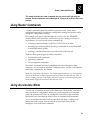
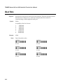
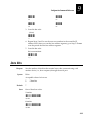
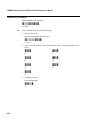
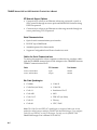
Manual Change Record
This page records the changes to this manual. The manual was originally released as version 001.
Version
Date
Description of Change
002
July 1997
This manual was changed to add information about the TRAKKER
Antares 2420 terminal and to document the new firmware version. The
new information includes:
•
The TRAKKER Antares 2420 terminal and features.
•
RS-232 serial communications on the TRAKKER Antares 2425
terminal.
•
TRAKKER Antares firmware version 2.10.
•
Multiple drives and applications on the TRAKKER Antares 2420
and 2425 terminals.
•
Western European keypad and character support on the TRAKKER
Antares 2420 and 2425 terminals.
All the functionality described in this manual applies to TRAKKER
Antares terminals with firmware version 1.X and higher. However,
this manual does describe features that are only available in TRAKKER
Antares firmware version 2.0 and higher. If you have a terminal with
firmware version 1.X, you should disregard the sections of this manual
that discuss the new features listed above.
003
December 1997
This manual was changed to add information about the TCP/IP radio
frequency network protocol option on the TRAKKER Antares 2425
terminal and to document the new firmware version. The new
information includes:
•
TRAKKER Antares 2420 and 2425 firmware version 2.20.
•
The TCP/IP network protocol option on the TRAKKER Antares
2425 terminal that allows a direct connection from the access points
to the host computer.
•
New terminal emulation features including auto-login, password
security for the TE Configuration Menu, and international
characters display support in TE applications.
The manual was also reorganized to move all information about
terminal emulation applications into a separate guide that ships with
the manual. The TRAKKER Antares Terminal Emulation User’s Guide
now contains all the information you need to configure and use
terminal emulation applications. All other information is covered in
this user’s manual.
004
July 1998
This manual was revised to include an addendum (Part No.
067224-001). The addendum provides information for firmware
version 3.2X:
•
Configuring row spacing and video mode.
•
Four-digit date format.
•
Configuring the optional 2MB flash memory.
•
ISBT Code 128.
•
Configuration commands to support COM4.
•
Configuring the T2425 to work with DHCP.
•
Receiving and transmitting files using YMODEM and
XMODEM-1K.
•
Information on the high density, long range, and high visibility
scan modules.
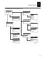
Contents
Contents
Before You Begin xv
Warranty Information xv
Safety Summary xv
Warnings and Cautions xvi
About This Manual xvii
1
Getting Started
What Are the TRAKKER Antares Terminals? 1-3
Accessories for the Terminal 1-4
Models and Options for the TRAKKER Antares Terminals 1-5
Equipment You Need to Get Started 1-6
Using the Terminal for the First Time 1-7
Unpacking the Terminal 1-7
Charging the Main Battery Pack 1-7
Connecting the Backup Battery 1-8
Installing the Main Battery Pack 1-10
Charging the Backup Battery 1-13
Turning On the Terminal for the First Time 1-13
Setting the Time and Date 1-16
Configuring the Serial Port Parameters 1-18
Configuring the T2425 and the RF Network 1-22
Configuring the Model 200 Controller, Host, and Access Points 1-23
Configuring the T2425 Network Parameters 1-23
Verifying That the T2425 Is Communicating Correctly 1-29
Starting the Application and Using the Terminal 1-30
Turning the Terminal On and Off 1-31
Enabling Bar Code Symbologies 1-32
What’s New on the TRAKKER Antares Terminals 1-34
Using This Manual With Older Firmware Versions 1-34
Ordering the Firmware Upgrade Kit 1-35
Where Do You Go From Here? 1-36
v
TRAKKER Antares 2420 and 2425 Hand-Held Terminal User’s Manual
2
Learning How to Use the Terminal
TRAKKER Antares Terminal Features 2-3
Using the Keypad 2-4
Finding the Special Keys 2-4
How to Type the Characters Printed on the Keypad 2-6
Using the Function Left/Right and Shift Keys 2-7
Capitalizing All Characters 2-8
How to Use the Cursor Keys 2-8
Using the Western European Keypad 2-9
Quick Reference Keypad Chart 2-12
How to Use the Terminal’s Screen 2-15
Using the Screen As a Viewport 2-16
Adjusting the Screen From the Keypad 2-16
Understanding the Icons 2-18
Understanding the Terminal’s Audio Signals 2-20
Locating the Serial Port 2-21
Learning About the Terminal’s Batteries 2-22
Main Battery Pack 2-22
Removing and Installing the Main Battery Pack 2-22
Charging the Main Battery Pack 2-27
Backup Battery 2-28
Charging the Backup Battery 2-28
Removing and Installing the Backup Battery 2-29
Disposing of the NiCad Backup Battery 2-33
Checking the Power Remaining in the Batteries 2-34
Recognizing a Low or Discharged Battery 2-34
Managing Your Battery Power 2-35
Using an External Power Supply 2-36
Defining the Terminal’s Memory and Drives 2-37
Using the Scan Module 2-38
Installing a Scan Module 2-39
Using the Standard Range Scan Module 2-40
Scanning Options 2-42
vi
Contents
3
Configuring the Terminal
How to Configure the Terminal 3-3
Learning About Configuration Parameters 3-3
Choosing the Symbologies the Terminal Decodes 3-4
Specifying How the Terminal Will Communicate 3-4
Controlling How the Terminal Will Operate 3-5
Configuring the Terminal With the Menu System 3-6
Exploring the Configuration and System Menus 3-8
Selecting Menus and Commands 3-9
Filling In Fields and Marking Check Boxes 3-10
Entering ASCII Control Characters 3-11
Exiting Screens and Saving Changes 3-13
Exiting the Configuration Menu 3-13
Exiting the TRAKKER Antares 2400 Menu System 3-14
Configuring the Terminal by Scanning Bar Codes 3-15
Saving Configuration Changes in Flash Memory 3-17
Restoring the Terminal’s Default Configuration 3-19
Upgrading the Firmware 3-20
Recording Your Terminal’s Configuration 3-23
4
Operating the Terminal in a Network
How the TRAKKER Antares Terminal Fits Into Your Network 4-3
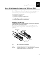
Using Serial Communications on the T2420 and T2425 4-9
Identifying the COM Ports 4-9
Connecting the Terminal to Another Device 4-10
Configuring and Using Serial Communications 4-11
Configuring the Terminal Via the Serial Port 4-12
Using RF Communications on the T2425 4-14
Planning the Network Connection 4-15
Configuring the Model 200 Controller 4-15
Configuring the Access Point 4-16
Configuring the T2425 4-16
Defining the RF Network Parameters 4-17
vii
TRAKKER Antares 2420 and 2425 Hand-Held Terminal User’s Manual
Using the Icons to Monitor RF Communications 4-19
Using the T2425 Between Access Points 4-21
Configuring the T2425 Over the Network 4-22
Configuring the T2425 From the Controller 4-22
Configuring the T2425 From the Host 4-23
Configuring the T2425 in a UDP Plus Network 4-23
Configuring the T2425 in a TCP/IP Direct Connect Network 4-25
Transferring Files in a TCP/IP Direct Connect Network 4-28
About Network Connectivity and Protocols 4-33
5
Using Custom Applications and Screen Mapping
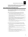
How To Download and Run Applications 5-3
About the TRAKKER Antares Programmable Terminals 5-4
Creating Applications for the Terminal 5-6
Using the PSK or EZBuilder to Develop Applications 5-6
Converting Applications Between JANUS and TRAKKER Antares 5-7
Converting IRL Programs 5-7
Converting the Application to a Binary File 5-8
Using the Serial Port to Transfer Applications and Files 5-8
Using the Model 200 Controller to Download Applications 5-11
Copying Files to the Model 200 Controller 5-12
Downloading Applications and Files to the T2425 5-13
Running the Application on the Terminal 5-16
Using Screen Mapping 5-19
Starting the Screen Mapping Application 5-19
Running Screen Mapping on Your Terminal 5-20
Requesting a New Template 5-20
Loading a Validation File 5-21
6
Troubleshooting
How to Use This Chapter 6-3
Finding and Solving Problems 6-4
Terminal Will Not Turn On 6-5
viii
Contents
Problems While Operating the Terminal 6-5
Problems While Configuring the Terminal 6-8
T2425 Will Not Communicate With RF Network Devices 6-13
Problems Transmitting Data Through the Serial Port 6-15
Problems Using the Screen Mapping Application 6-16
Bar Code Labels Will Not Scan 6-20
Guidelines for Managing Batteries 6-23
Booting and Resetting the Terminal 6-25
Booting the Terminal 6-25
Booting the Terminal on Resume 6-25
Using the Boot Menu 6-26
Resetting the Terminal 6-26
Maintaining and Cleaning the Terminal 6-28
Replacing the Antenna 6-28
Cleaning the Scan Module Window and Terminal Screen 6-30
7
Running Diagnostics
What Diagnostics Are Available? 7-3
Running Diagnostics From the Menu System 7-4
Defining the Diagnostics Screens 7-7
Defining the Software Diagnostics Screens 7-7
Application Events 7-7
Clear Task Profiles 7-8
Error Logger 7-8
Task Status 7-9
Defining the Hardware Diagnostics Screens 7-10
Battery Monitor 7-10
Battery Status 7-11
Beeper Test 7-12
Destructive RAM Test 7-13
Display Test 7-14
Hardware Configuration 7-15
Keypad Test 7-16
Radio Test 7-17
Scanner Test 7-18
Serial Loopback 7-19
Defining the System Diagnostics Screens 7-20
Access Point 7-20
Application Efficiency 7-21
Malloc Application Information 7-22
ix
TRAKKER Antares 2420 and 2425 Hand-Held Terminal User’s Manual
Malloc Firmware Information 7-23
Serial Port Test 7-24
Subsystem Versions 7-25
Suspend-Resume Test 7-26
8
Reader Command Reference
Using Reader Commands 8-3
Using Accumulate Mode 8-3
Enter Accumulate Mode 8-5
Backspace 8-5
Clear 8-6
Enter 8-6
Exit Accumulate Mode 8-6
Operating Reader Commands 8-7
Backlight On and Off 8-7
Change Configuration 8-8
Default Configuration 8-8
Multiple-Read Labels 8-9
Reset Firmware 8-9
Save Configuration in Flash Memory 8-10
Scanner Trigger On and Off 8-10
Test and Service Mode 8-11
File Management Reader Commands 8-12
Abort Program 8-12
Delete File 8-12
Receive File 8-13
Receive File Through the Serial Port 8-13
Receive File Via RF Communications 8-14
Rename File 8-16
Run Program 8-17
Transmit File 8-18
Transmit File Through the Serial Port 8-18
Transmit File Via RF Communications 8-19
9
Configuration Command Reference
Using Configuration Commands 9-3
Configuration Commands Listed by Category 9-4
Entering Variable Data in a Configuration Command 9-6
x
Contents
Acknowledgement Delay Lower Limit 9-7
Acknowledgement Delay Upper Limit 9-8
Append Time 9-10
Automatic Shutoff 9-10
Baud Rate 9-12
Beep Volume 9-13
Codabar 9-14
Code 11 9-15
Code 16K 9-16
Code 2 of 5 9-17
Code 39 9-18
Code 49 9-22
Code 93 9-23
Code 128 9-24
Command Processing 9-25
Configuration Commands Via Serial Port 9-28
Controller Connect Check Receive Timer 9-29
Controller Connect Check Send Timer 9-30
Controller IP Address 9-32
Data Bits 9-33
Decode Security 9-34
Default Router 9-35
Display Backlight Timeout 9-36
Display Contrast 9-38
Display Font Type 9-39
End of Message (EOM) 9-40
Flow Control 9-41
Handshake 9-42
Host IP Address 9-43
Interleaved 2 of 5 9-45
Keypad Caps Lock 9-47
Keypad Clicker 9-47
Keypad Type 9-48
LRC (Longitudinal Redundancy Check) 9-49
xi
TRAKKER Antares 2420 and 2425 Hand-Held Terminal User’s Manual
Maximum Retries 9-49
MSI 9-51
Network Activate 9-52
Network Loopback 9-52
Network Port 9-53
Parity 9-55
Plessey 9-55
Poll (Polling) 9-56
Postamble 9-57
Preamble 9-58
RAM Drive Size 9-60
Resume Execution 9-62
RF Domain 9-63
RF Inactivity Timeout 9-64
RF Roaming Flag 9-65
RF Security Identification 9-66
RF Security ID Override 9-67
RF Transmit Mode 9-68
RF Wakeup On Broadcast 9-69
Scan Ahead 9-69
Scanner Mode 9-70
Scanner Redundancy 9-71
Scanner Selection 9-72
Scanner Timeout 9-74
Scanner Trigger 9-75
Start of Message (SOM) 9-76
Stop Bits 9-77
Subnet Mask 9-77
TCP/IP Maximum Transmit Timeout 9-79
Terminal IP Address 9-80
Time and Date 9-82
Time in Seconds 9-83
Timeout Delay 9-84
UPC/EAN 9-85
xii
Contents
A
Appendix A — Terminal Specifications
Physical and Environmental Specifications A-3
Default Configuration A-8
Configuration Commands by Syntax A-12
B
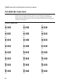
Appendix B — Full ASCII Charts
Full ASCII Table B-3
Full ASCII Bar Code Chart B-6
Control Characters B-6
Symbols and Punctuation Marks B-7
Numbers B-8
Uppercase Letters B-9
Lowercase Letters B-10
C
G
I
Appendix C — International Character Support
TRAKKER Antares Terminal Font Set C-3
Glossary
Index
xiii
nugget
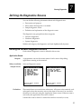
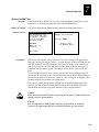
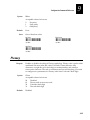
Before You Begin
code39
Before You Begin
This section introduces you to standard warranty provisions, safety
precautions, warnings and cautions, document formatting conventions, and
sources of additional product information. A list of Intermec manuals is also
provided to guide you in finding the appropriate information.
Warranty Information
To receive a copy of the standard warranty provision for this product, contact
your local Intermec support services organization. In the U.S. call
1-800-755-5505, and in Canada call 1-800-688-7043. Otherwise, refer to the
Worldwide Sales & Service list that ships with this manual for the address and
telephone number of your Intermec sales organization.
Safety Summary
Your safety is extremely important. Read and follow all warnings and cautions
in this book before handling and operating Intermec equipment. You can be
seriously injured, and equipment and data can be damaged if you do not follow
the safety warnings and cautions.
Do not repair or adjust alone Do not repair or adjust energized equipment alone
under any circumstances. Someone capable of providing first aid must always
be present for your safety.
First aid Always obtain first aid or medical attention immediately after an
injury. Never neglect an injury, no matter how slight it seems.
Resuscitation Begin resuscitation immediately if someone is injured and stops
breathing. Any delay could result in death. To work on or near high voltage,
you should be familiar with approved industrial first aid methods.
Energized equipment Never work on energized equipment unless authorized
by a responsible authority. Energized electrical equipment is dangerous.
Electrical shock from energized equipment can cause death. If you must
perform authorized emergency work on energized equipment, be sure that you
comply strictly with approved safety regulations.
Note: For laser compliance and safety information, refer to the manual supplement
that shipped with your TRAKKER Antares 2420 or 2425 terminal.
xv
TRAKKER Antares 2420 and 2425 Hand-Held Terminal User’s Manual nugget
code39
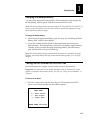
Warnings and Cautions
The warnings and cautions in this manual use the following format.
Warning
A warning alerts you of an operating procedure, practice, condition, or
statement that must be strictly observed to avoid death or serious injury to the
persons working on the equipment.
Avertissement
Un avertissement vous avertit d’une procédure de fonctionnement, d’une
méthode, d’un état ou d’un rapport qui doit être strictement respecté pour
éviter l’occurrence de mort ou de blessures graves aux personnes manupulant
l’équipement.
Caution
A caution alerts you to an operating procedure, practice, condition, or
statement that must be strictly observed to prevent equipment damage or
destruction, or corruption or loss of data.
Conseil
Une précaution vous avertit d’une procédure de fonctionnement, d’une
méthode, d’un état ou d’un rapport qui doit être strictement respecté pour
empêcher l’endommagement ou la destruction de l’équipement, ou l’altération
ou la perte de données.
Notes: Notes are statements that either provide extra information about a topic or
contain special instructions for handling a particular condition or set of circumstances.
xvi
nugget
Before You Begin
code39
About This Manual
This manual contains all of the information necessary to install, configure,
operate, and troubleshoot the TRAKKER® Antares™ 2420 and 2425 terminals.
This manual was written for two audiences:
•
All users who need to know how to use the terminal to collect data.
•
MIS personnel, operations personnel, analysts, and programmers who need
to know how to install, configure, test, and use the terminal to operate in a
network. You should have a good knowledge of your company’s network
and data collection software. You should be familiar with data
communications and network protocols.
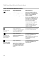
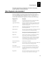
What You Will Find in This Manual
This table summarizes the information in each chapter and appendix.
Chapter
What You Will Find
1
Summarizes the terminal’s features, functions, and accessories. Explains
how to get your TRAKKER Antares 2420 or 2425 terminal started for the
first time.
2
Describes and explains how to use your terminal’s keypad, screen, audio
signals, serial port, batteries, memory and drives, and scan modules.
3
Explains how to configure your terminal.
4
Describes serial communications and the 2.4 GHz radio frequency
network and explains how to install and configure your terminal to
communicate with other devices.
5
Introduces the TRAKKER Antares 2420 and 2425 programmable
terminals and explains how to download and run applications. Also,
explains how to use the screen mapping application.
6
Lists solutions for the problems you may have while operating your
terminal. Also, explains how to boot or reset the terminal.
7
Explains how to use the terminal’s built-in diagnostics to research and
troubleshoot problems.
8
Describes the commands that you can use to change the TRAKKER
Antares terminal’s operation or manage files.
9
Describes the commands that you can scan to configure the TRAKKER
Antares terminal.
xvii
TRAKKER Antares 2420 and 2425 Hand-Held Terminal User’s Manual nugget
code39
What You Will Find in This Manual (continued)
Chapter
What You Will Find
A
Lists the TRAKKER Antares terminal’s specifications, configuration
command names and syntax, and the terminal’s default configuration
settings.
B
Contains reference tables including the full ASCII table and full ASCII
bar code chart.
C
Contains a reference table that lists the complete set of English and
Western European characters that you can display on a TRAKKER
Antares 2420 or 2425 terminal.
Note: For information about using IBM 3270, IBM 5250, or VT/100/220/320 and
ANSI terminal emulation applications, see the TRAKKER Antares Terminal
Emulation User’s Guide that ships with this manual.
Terminology
You should be aware of how these terms are being used in this manual:
Term
Description
Host
The term “host” refers to a personal computer or other
computer that communicates with the terminal.
T2420
The term “T2420” indicates the specific type of terminal, the
TRAKKER Antares 2420 terminal.
T2425
The term “T2425” indicates the specific type of terminal, the
TRAKKER Antares 2425 terminal.
Terminal
The generic term “terminal” indicates any TRAKKER Antares
terminal. More specific terms, such as “TRAKKER Antares
2425 terminal” or “T2420,” indicate a specific type of terminal.
TRAKKER Antares
terminal
The generic term “TRAKKER Antares terminal” indicates any
TRAKKER Antares terminal. More specific terms, such as
“TRAKKER Antares 2420 terminal” or “T2425,” indicate a
specific type of terminal.
TRAKKER Antares
The term “TRAKKER Antares” identifies the product family of
TRAKKER Antares hand-held terminals.
For definitions of the technical terms used in this manual, see the glossary.
xviii
nugget
Before You Begin
code39
Conventions for Input From a Keypad or Keyboard
This table describes the formatting conventions for input from PC or host
computer keyboards and terminal keypads:
Convention
How to Interpret the Convention
Special text
Shows the command as you should enter it into the terminal. See
“Conventions for Commands” later in this chapter.
Italic text
Indicates that you must replace the parameter with a value. See
“Conventions for Commands” later in this chapter.
Bold text
Indicates the keys you must press on a PC or host computer
keyboard. For example, “press Enter” means you press the key
labeled “Enter” on the PC or host computer keyboard.
T3,
––L
Shows the key you must press on the terminal. For example,
“press
” directs you to press the Enter key on the terminal
keypad.
Shows a series of terminal keys you must press and release in the
order shown. For example, “Press
to run the
TRAKKER Antares 2400 Menu System.”
T3,
Shows a series of terminal keys you must press simultaneously.
Also, you must press and hold the keys in the order shown. For
example, “Press –
–
to reset the terminal.”
L
Conventions for Bar Codes
You can scan the bar codes listed in this manual to enter data or perform a
command. The bar code labels in this manual are printed in the Code 39
symbology. Each bar code includes the name and human-readable
interpretation. For example:
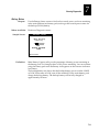
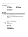
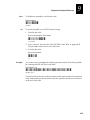
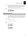
Change Configuration
Name
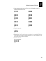
*$+*
Bar code (Code 39)
Human-readable
interpretation
*$+*
242XU.146
The asterisks (*) at the beginning and end of the human-readable interpretation
are the start and stop codes for a Code 39 bar code label. If you are using a bar
code printing utility, it may automatically supply the asterisks as the start and
stop code, so that you only need to type the actual text of the command. You
can also create and print configuration labels and reader command labels in
Code 93, which has its own start and stop codes.
xix
TRAKKER Antares 2420 and 2425 Hand-Held Terminal User’s Manual nugget
code39
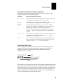
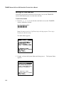
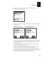
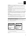
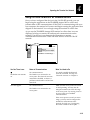
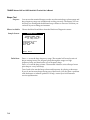
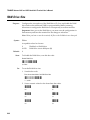
Conventions for Software Screens and Messages
This manual includes illustrations that represent how the TRAKKER Antares
2420 and 2425 terminals display software screens and messages. Here are two
examples:
MAIN
MENU
Configuration Menu
Diagnostics Menu
System Menu
About TRAKKER 2400
File
Name:
_` Select item
[Enter] Next screen
[F1] Help
[Esc] Exit
TNAPP
F
242XU.007
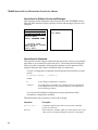
Conventions for Commands
This manual includes sample commands that are shown exactly as you should
type them on your terminal or network device. The manual also describes the
syntax for many commands, defining each parameter in the command. This
example illustrates the format conventions used for commands:
To send a configuration command from the Model 200 Controller, use this
syntax:
$+command[command]...[command n]
where:
$+
is the Change Configuration command.
command
is a configuration command. For example, BV is the command to
set the Beep Volume on the terminal. Enter the command BV0 to
turn off the beep volume.
You can include multiple configuration command parameters in the
command to configure the terminal.
This table defines the conventions used in the example:
xx
Convention
Description
Special font
Commands appear in this font. You enter the command
exactly as it is shown.
Italic text
Italics indicate a variable, which you must replace with a real
value, such as a number, filename, keyword, or command.
nugget
Before You Begin
code39
Conventions for Commands (continued)
Convention
Description
[]
Brackets enclose a parameter that you may omit from the
command. Do not include the brackets in the command.
Required parameters
If a parameter is not enclosed in brackets [ ], the parameter is
required. You must include the parameter in the command;
otherwise, the command will not execute correctly.
where
This word introduces a list of the command’s parameters and
explains the values you can specify for them.
Other Intermec Manuals
You may need to refer to the manuals listed below for additional information
about your TRAKKER Antares 2420 or 2425 terminal, accessories, or the
2.4 GHz radio frequency network. To order additional manuals, contact your
local Intermec representative or distributor.
Manual
Intermec
Part No.
0110/0111/0115 Access Point User’s Manual
065053
The Bar Code Book
051241
EZBuilder Getting Started Guide
066450
EZBuilder Tutorial
066449
Model 200 Controller System Manual
063439
Model 200 Controller Technical Reference Manual
064398
TRAKKER Antares 2400 Series Battery Pack Instruction Sheet
064216
TRAKKER Antares 2400 Series Belt Clip and Belt Instruction Sheet
064218
TRAKKER Antares 2400 Series Handstrap Instruction Sheet
064217
TRAKKER Antares 2400 Series Holster and Belt Instruction Sheet
064215
TRAKKER Antares 2400 Series Module for Cabled Scanners Instruction Sheet
064219
TRAKKER Antares 2400 Series Standard Range Scan Module Instruction Sheet
064220
TRAKKER Antares 2400 Series Vehicle-Mount Holder Instruction Sheet
064214
TRAKKER Antares 2420 and 2425 Hand-Held Terminal Getting Started Guide
064183
TRAKKER Antares Application Development Tools System Manual
064433
TRAKKER Antares Optical Link Adapter Quick Reference Guide
065826
TRAKKER Antares TD2400 Communications Dock Quick Reference Guide
065555
TRAKKER Antares Terminal Emulation User’s Guide
066694
TRAKKER Antares TZ2400 Battery Charger Quick Reference Guide
064213
xxi
nuggetf
code39
1
Getting Started
nuggetf
code39
nuggetf
Getting Started
code39
1
This chapter introduces the TRAKKER Antares 2420 and 2425 terminals and
explains how to get your new terminal up and running.
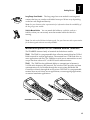
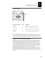
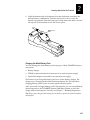
What Are the TRAKKER Antares Terminals?
The TRAKKER Antares 2420 and 2425 terminals are hand-held data collection
terminals. You use these programmable terminals to run custom applications,
terminal emulation applications, or screen mapping applications.
E
R
A
K
E
R
A
N
T
24
S
25
You use the TRAKKER Antares 2420 (T2420) terminal to collect data and
periodically upload the data to a host computer via serial (wired)
communications. The TRAKKER Antares 2425 (T2425) terminal transmits data
via serial communications or radio frequency (RF) communications in
Intermec’s 2.4 GHz RF network.
T
R
A
K
CGA-compatible display
Scan module
Keypad
F5
9
I/O
F4
6
F3
8
F2
1
0
4
2
7
5
3
F1
Antenna for
RF communications
er
Ent
Fn
Fn
L
E
J
D
R
C
A
O
I
L
X
R
P
Esc
W
Q
K
Y
S
M
G
F
T
N
H
B
V
b
Ta
U
Z
Rechargeable
batteries
Serial port
242XU.030
The TRAKKER Antares terminals are ergonomically designed to make data
collection easy and include these features:
•
Scan module accessory for bar code data collection.
•
CGA-compatible display, angled for easy viewing.
•
Keypad with 56 keys to support data collection. The terminal ships with a
keypad to match the application or language you ordered.
•
Serial port to support RS-232 communications.
•
Rechargeable lithium-ion battery pack (sold separately) for main power and
rechargeable NiCad backup battery for memory backup.
•
Adjustable antenna on the T2425 supports 2.4 GHz radio frequency
communications.
1-3
TRAKKER Antares 2420 and 2425 Hand-Held Terminal User’s Manual nuggetf
code39
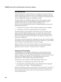
Accessories for the Terminal
You can use these accessories (sold and ordered separately) with the TRAKKER
Antares 2420 and 2425 terminals:
TZ2400 Battery Charger The charger lets you charge up to four lithium-ion
battery packs at one time. The battery charger senses when a battery pack is
fully charged and will not overcharge it, ensuring long and consistent battery
pack life.
Belt Clip The belt clip lets you attach the terminal to your belt and have it
hang at your side so you can have both hands free. The belt clip snaps around
your belt and a Velcro strap holds the terminal to the belt clip.
2425S
TRA
KKE
R ANTARE
F5
I/O
F4
F3
9
F2
F1
8
6
7
5
4
3
2
1
0
Enter
Fn
Fn
E
R
D
L
J
C
I
B
O
H
A
N
G
T
M
F
S
L
Y
R
K
X
Q
Esc
W
P
V
Tab
U
25
24
Z
TD2400 Communications Dock When you place the terminal in the dock, it
allows the terminal to communicate with a host computer or other device
through the serial port. You must connect a power supply to the dock to
operate the terminal and charge the batteries.
Handstrap The elastic handstrap attaches to the back of the terminal to let you
hold the terminal easily and securely for long periods of use.
Holster The holster is a convenient way for you to carry the terminal on your
belt when you are not using it. The holster attaches to your belt and holds the
terminal at your side.
20
RES
T
Esc
Y
N
H
B
M
A
G
S
X
L
F
R
W
Q
K
P
V
U
Z
Tab
Fn
L
I
C
O
Fn
R
D
J
E
Ente
r
1
0
4
2
7
5
3
F1
8
F2
6
F3
9
I/O
F4
F5
TR
AK
KE
R
ANTA
24
Module for Cabled Scanners This module has a scanner port that lets you
attach a wand, laser scanner, or CCD scanner for bar code data collection.
Optical Link Adapter When the optical link adapter is connected to the
terminal, it allows the terminal to communicate with a host computer or other
device through the serial port. You can also connect a power supply to the
optical link adapter to charge the batteries.
Standard Range Scan Module The standard range laser scan module is an
integrated scanner that lets you scan bar code labels from up to 30 inches
away depending on the bar code height and density.
1-4
nuggetf
1
Getting Started
code39
Long Range Scan Module The long range laser scan module is an integrated
scanner that lets you scan bar code labels from up to 20 feet away depending
on the bar code height and density.
Note: See your Intermec sales representative for information about the availability of
the long range scan module.
Vehicle-Mount Holder You can attach this holder to a vehicle, such as a
forklift, so that you can securely store the terminal while the vehicle is
moving.
I/O
F5
9
6
3
0
Enter
E
O
T
Y
Esc
Note: You also need a lithium-ion battery pack. See your Intermec sales representative
for the battery packs that are currently available.
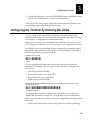
Models and Options for the TRAKKER Antares Terminals
The TRAKKER Antares family of terminals includes these models:
T2420 The T2420 is a programmable data collection terminal that has 512K of
RAM reserved for custom applications. The terminal has a 750K flash drive to
store applications and files. The T2420 has a serial port to transmit data to and
accept data from a host or PC via RS-232 serial communications.
T
A
R
24
E
S
S
25
20
T2425 The T2425 has the additional ability to communicate in Intermec’s
2.4 GHz radio frequency (RF) network. The wireless T2425 provides real-time
communications to a host either through the access points and Model 200
Controller or directly through the access points. The T2425 is a programmable
terminal that can run client/server applications, screen mapping applications,
or terminal emulation applications.
E
N
A
R
E
K
K
A
R
9
6
F3
8
F2
3
5
J
E
E
nte
D
O
I
C
Y
N
M
S
H
G
sc
E
X
W
V
P
U
Z
Z
U
TRAKKER Antares 2420
Ta
b
K
Q
F
R
L
E
X
W
Ta
V
P
b
K
Q
F
R
L
sc
A
T
L
Fn
B
Y
T
N
S
H
M
B
A
G
Fn
L
I
C
O
Fn
Fn
R
R
D
J
E
E
nte
r
r
1
1
0
0
4
4
2
2
7
7
5
3
F1
8
F2
6
F3
9
I/O
F4
F5
T
F5
F4
I/O
F1
X
Tab
R
S
W
A
R
V
Z
J
N
M
Q
U
T
I
L
P
24
D
H
G
K
N
C
B
F
A
Fn R
A
R
2
Fn L
E
5
1
K
8
4
K
7
A
F4
F3
R
F2
T
F1
TRAKKER Antares 2425
242XU.035
1-5
TRAKKER Antares 2420 and 2425 Hand-Held Terminal User’s Manual nuggetf
code39
These options are available for the TRAKKER Antares 2420 terminal:
•
Programmable terminal with alphanumeric keypad available to support
English or Western European languages
•
Extended storage drive, 2MB or 4MB, for custom applications and files
These options are available for the TRAKKER Antares 2425 terminal:
•
UDP Plus (Model 200 Controller network) or TCP/IP (direct connect) radio
frequency network protocol
•
IBM 3270 terminal emulation application and keypad
•
IBM 5250 terminal emulation application and keypad
•
VT100/220/320 and ANSI terminal emulation application and keypad
•
Screen mapping for 3270, 5250, or VT/ANSI (only UDP Plus terminals)
•
Programmable terminal with alphanumeric keypad available to support
English or Western European languages
This manual tells you how to use the features and options available on all
models of the TRAKKER Antares terminals.
Equipment You Need to Get Started
To use the TRAKKER Antares 2420 terminal, you need this equipment:
•
TRAKKER Antares 2420 terminal
•
Lithium-ion battery pack
•
Battery charger
•
TRAKKER Antares Programmer’s Software Kit or EZBuilder (to develop
applications)
•
TD2400 communications dock or TRAKKER Antares optical link adapter
•
RS-232 cable (3-wire or 5-wire null modem) to connect the terminal to a host
To use the TRAKKER Antares 2425 terminal, you need this equipment:
1-6
•
TRAKKER Antares 2425 terminal
•
Lithium-ion battery pack
•
Battery charger
•
Access point
•
Model 200 Controller (software version 2.2 or higher) for T2425s that use
the UDP Plus network protocol option
•
TRAKKER Antares Programmer’s Software Kit or EZBuilder (to develop
applications)
nuggetf
Getting Started
code39
1
To use the serial port on the T2425, you also need this equipment:
•
TD2400 communications dock or TRAKKER Antares optical link adapter
•
RS-232 cable (3-wire or 5-wire null modem) to connect the terminal to a host
Note: Intermec recommends that you keep at least two lithium-ion battery packs on
hand so that you can use one battery pack while the other is recharging.
Using the Terminal for the First Time
Follow these steps to start using your new TRAKKER Antares 2420 or 2425
terminal:
1. Unpack the terminal and documentation.
2. Charge the main battery pack (sold separately).
3. Connect the backup battery.
4. Install the charged main battery pack.
5. Charge the backup battery.
6. Turn on the terminal.
7. Set the time and date.
8. Configure the serial port parameters.
9. (T2425 only) Configure the T2425 and the RF network devices.
10. Start the application and use the terminal.
These steps are described in detail in the next sections.
Unpacking the Terminal
When you remove the terminal from its box, save the box and shipping
material in case you need to ship or store the terminal. Check the contents of
the box against the invoice for completeness and contact your local Intermec
service representative if there is a problem.
The terminal ships with a getting started guide, safety documents, and scan
module documents. The scan module you ordered is already installed on the
terminal.
Charging the Main Battery Pack
The terminal’s main battery pack is a lithium-ion battery. You must fully charge
the battery pack before you can use the terminal. The lithium-ion battery pack
is the main power source for the terminal.
1-7
TRAKKER Antares 2420 and 2425 Hand-Held Terminal User’s Manual nuggetf
code39
Tip: Keep a spare charged main battery pack on hand to operate the terminal without
interruption.
To charge the main battery pack
•
Place the battery pack in an empty slot in the battery charger. The battery
pack is fully charged in about two hours. For help, see the documentation
that came with your battery charger.
You can also use the TD2400 communications dock or the optical link adapter
to trickle-charge the battery pack. You must have a power supply connected to
the dock or optical link adapter to charge the battery pack. For help, see the
TRAKKER Antares TD2400 Communications Dock Quick Reference Guide or the
TRAKKER Antares Optical Link Adapter Quick Reference Guide.
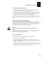
Connecting the Backup Battery
A NiCad battery backs up all memory and the real-time clock while you change
the main battery pack. The backup battery is shipped inside the terminal, but it is
not connected.
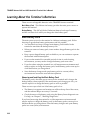
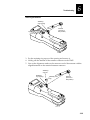
To connect the backup battery
1. Open the battery door by pushing down on the battery door latch and
sliding it toward the bottom end of the terminal. Lift up the top edge of the
battery door to remove it.
TOP
Battery door
latch
BOTTOM
242XU.079
1-8
nuggetf
Getting Started
code39
1
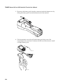
2. Find the two connectors in the backup battery compartment. One connector
is attached to the backup battery. The other connector is attached to the
terminal. Firmly push the two battery wire connectors together until they
lock. (The connectors are keyed so they cannot be connected incorrectly.)
Battery wire
connectors
Backup
battery
242XU.086
3. Gently fold and push the backup battery wires into the open area of the
backup battery compartment near the wall.
Folded wires
242XU.089
4. Leave the battery door off to continue with the next procedure, “Installing
the Main Battery Pack.”
1-9
TRAKKER Antares 2420 and 2425 Hand-Held Terminal User’s Manual nuggetf
code39
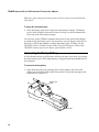
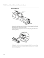
Installing the Main Battery Pack
Install the fully charged main (lithium-ion) battery pack into the TRAKKER
Antares 2420 or 2425 terminal.
Note: You should always keep a charged main battery pack installed in the terminal to
maximize the backup battery’s life.
To install the main battery pack
1. If the battery door is not off, open the battery door by pushing down on the
battery door latch and sliding it toward the bottom end of the terminal. Lift
up the top edge of the battery door to remove it.
TOP
Battery door
latch
BOTTOM
242XU.079
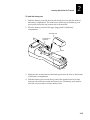
2. Hold the battery pack with the flat side facing down toward the inside of
the battery compartment. The small arrow on the top of the battery pack
must point toward the top (screen) end of the terminal.
3. Place the battery pack into the upper (larger) half of the battery
compartment.
1-10
nuggetf
Getting Started
code39
1
Inserting the Battery Pack
Connector end
Connector pin
(2 places)
Slots
242XU.082
4. Hook the slots on the bottom of the battery pack into the slots on the bottom
of the battery compartment.
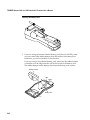
5. Slide the battery pack toward the top end of the terminal until it fits and
locks into the connectors inside the bottom case. The battery pack must be
all the way forward to close the battery door.
242XU.102
1-11
TRAKKER Antares 2420 and 2425 Hand-Held Terminal User’s Manual nuggetf
code39
6. If you are using an Intermec-labeled battery pack (Part No. 063278), make
sure you remove the rubber bumper from the inside of the battery door.
Otherwise, you will not be able to close the battery door.
If you are using a Sony-labeled battery pack, make sure the rubber bumper
is installed over the ridge near the wall on the inside of the battery door.
The rubber bumper on the battery door keeps the battery pack in place.
Rubber bumper
Wall
Ridge
Battery door
242XU.148
7. Hook the bottom edge of the battery door into the bottom case above the
backup battery compartment. Push the door down to close it over the
battery compartment. Push the battery door latch down and slide it toward
the top end of the terminal to lock the door in place.
Battery door
latch
242XU.088
1-12
nuggetf
Getting Started
code39
1
Charging the Backup Battery
You must fully charge the backup battery. The main battery pack charges the
backup battery when required with the terminal turned on or off.
Note: The backup battery charger operates between 32°F and 104°F (0°C and 40°C). If
you are using the terminal in an environment that is outside this temperature range,
the backup battery will not charge.
To charge the backup battery
1. Install a fully charged main battery pack. For help, see “Installing the Main
Battery Pack” earlier in this chapter.
2. Leave the terminal turned off and let the main battery pack charge the
backup battery. The backup battery will be fully charged in approximately
18 hours. After you finish charging the backup battery, the main battery
pack still has most of its power remaining.
Note: The backup battery charges enough within 20 minutes to operate the terminal.
However, the backup battery will only provide limited backup power if it is not fully
charged.
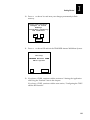
Turning On the Terminal for the First Time
Once the batteries are charged, you are ready to turn on the terminal.
Important: You must have a scan module attached to turn on the terminal. A scan
module is installed at the Intermec factory. For help, see “Using the Scan Module” in
Chapter 2.
To turn on the terminal
L
1. Press the
key on the top left of the keypad. The terminal runs POST
(power-on self test) and then the Boot Menu appears.
BOOT
MENU
b
-
Boot
l
-
Run
q
-
Power
POWER
DOWN
System
Loader
IN
Down
60
SEC
242XU.104
1-13
TRAKKER Antares 2420 and 2425 Hand-Held Terminal User’s Manual nuggetf
code39
Note: If the Boot Menu screen does not appear, you may have a problem with the
batteries. Make sure the main battery pack is fully charged and installed correctly.
For help, see Chapter 6, “Troubleshooting.”
!
2. Press
to boot the terminal and initialize the firmware. The TRAKKER
Antares screen appears.
The next screen or messages you see depend on the type of application that
is loaded on the terminal.
T2420 or T2425 Programmable Terminal The sample application screen
appears with information about the radio. A T2420 does not have a radio
(see the next illustration) and the radio is not initially enabled on the T2425.
96/01/01
No Radio
in
12:00:00
System.
242XU.176
T2425 With Terminal Emulation Application A warning screen about creating
a TE configuration file may appear. Press
to create the file and continue.
A terminal emulation application welcome screen appears similar to the
examples shown next.
1-14
nuggetf
Getting Started
code39
1
Terminal Emulation Application Welcome Screens
Intermec
TRAKKER Antares
3270
Terminal
Emulation
Version 04.1
Intermec
TRAKKER Antares
VT/ANSI
Terminal
Emulation
Version 04.1
242XU.070
Note: At the TE welcome screen, you can press
to access the TE
Configuration Menu and configure your terminal emulation application. For help,
see the TRAKKER Antares Terminal Emulation User’s Guide.
Next, the T2425 tries to connect to the Model 200 Controller or the host in a
TCP/IP direct connect network. You will see messages like:
Waiting for
connection to
controller...
Unable to
establish connection
to host.
Since you have not configured the RF network parameters, the T2425
cannot start a terminal emulation session.
T2425 Screen Mapping Terminal A welcome screen appears briefly and then
the File name screen appears. You need to configure the RF network
parameters so you can download a template from the Model 200 Controller.
File
name:
242XU.060
3. Configure the terminal now. Follow the instructions in the next section,
“Setting the Time and Date.”
1-15
TRAKKER Antares 2420 and 2425 Hand-Held Terminal User’s Manual nuggetf
code39
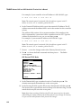
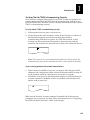
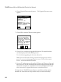
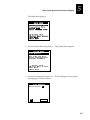
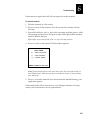
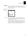
Setting the Time and Date
You need to set the time and date on the terminal. You use the TRAKKER
Antares 2400 Menu System to set the time and date.
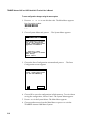
To set the time and date
T3 ,
1. Press
or scan this bar code label to access the TRAKKER
Antares 2400 Menu System.
Enter Test and Service Mode
*..-.*
*..-.*
T
Note: You must press the (Left Enter) key in this key sequence. The
located just under the
key.
L
T key is
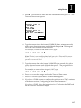
The Main Menu appears.
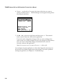
242XU.001
V
2. Press to choose the System Menu and then press
appears.
SYSTEM MENU
File Manager
Load Default Values
Set Time and Date
Store Configuration
Upgrade Firmware
_` Select item
[Enter] Next screen
[F1] Help
[Esc] Exit
242XU.051
1-16
. The System Menu
nuggetf
Getting Started
code39
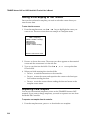
V
3. Press to choose the Set Time and Date command and then press
Time and Date screen appears.
1
. The
TIME AND DATE
Current time is
12:00:00
New time:
12:39:00
Current date is
96/01/01
New date (YY/MM/DD):
OK
CANCEL
242XU.009
4. Type the current time in the format HH MM SS (hours, minutes, seconds)
with a space character between each field and then press . The program
fills in the colon character in the time field.
V
For example, to enter the time 04:05:03 P.M., type:
V
Note: The time is not actually updated until you exit the Time and Date screen.
When you set the time, set the time ahead so that the correct time is saved when
you exit the screen in Step 6.
5. Type the current date in the format YY MM DD (year, month, day) with a
space character between each field and then press . The program fills in
the slash character in the date field.
V
For example, to enter the date August 9, 1997, type:
6.
7.
V
Press to save the changes and exit the Time and Date screen.
Press ? to exit the System Menu. The Main Menu appears.
8. If you have a T2420 or want to configure the serial port on a T2425, continue
with the next section, “Configuring the Serial Port Parameters.”
If you have a T2425, follow the instructions for “Configuring the T2425 and
the RF Network” later in this chapter.
1-17
TRAKKER Antares 2420 and 2425 Hand-Held Terminal User’s Manual nuggetf
code39
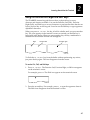
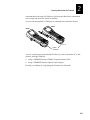
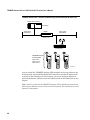
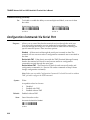
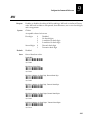
Configuring the Serial Port Parameters
You use the terminal’s serial port and a communications dock or optical link
adapter to transfer data in a wired network between the T2420 or T2425 and a
host computer, printer, or other RS-232 serial device.
To power
supply
Host computer
Terminal in TD2400
communications dock
242XU.160
You need to set these serial port parameters to have the terminal communicate
with a host computer or serial device in a wired network:
Serial Port Parameter
Default Value
Baud rate
19200
Data bits
7
EOM (End of Message)
\x03 (hexadecimal value for ETX)
Flow control
None
Handshake
Disabled
LRC
Disabled
Parity
Even
Poll (Polling)
Disabled
SOM (Start of Message)
\x02 (hexadecimal value for STX)
Stop bits
1
Timeout delay
10 seconds
The values you set for the terminal’s serial port must match the values set for
the host’s (or other device’s) serial port. You use the TRAKKER Antares 2400
Menu System to set the parameters on the terminal. For a detailed definition of
these parameters, see Chapter 9, “Configuration Command Reference.”
1-18
nuggetf
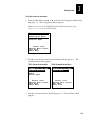
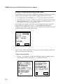
To set the serial port parameters
Getting Started
code39
1
: V
1. From the Main Menu, press or to choose the Configuration Menu and
then press
. The Configuration Menu appears.
Note: If you are not in the TRAKKER Antares 2400 Menu System, press
to access the Main Menu.
T3 ,
CONFIGURATION
MENU
Symbologies Menu
Communications Menu
Terminal Menu
_` Select item
[Enter] Next screen
[F1] Help
[Esc] Exit
242XU.010
V
2. Press to choose the Communications Menu and then press
Communications Menu appears.
T2425 Communications Menu
. The
T2420 Communications Menu
COMMUNICATIONS MENU
COMMUNICATIONS MENU
Primary Network
Advanced Network
Radio
Serial Port
Serial Port
_` Select item
[Enter] Next screen
[F1] Help
[Esc] Exit
_` Select item
[Enter] Next screen
[F1] Help
[Esc] Exit
242XU.070
V
3. Press to choose Serial Port and then press
appears.
. The Serial Port screen
1-19
TRAKKER Antares 2420 and 2425 Hand-Held Terminal User’s Manual nuggetf
code39
Serial Port Screen
SERIAL
PORT
Baud Rate: 19200
Parity: Even
Data Bits: 7
Stop Bits: 1
Timeout Delay:
10 sec
Flow Control:
None
LRC: Enabled
Commands via Serial
Port:Enabled No TMF
` more
242XU.156
W
4. In each field, press to toggle through the field options and select a value.
Once the correct value is displayed, press to move to the next field.
V
You must set each of the terminal’s serial port parameters to match your
host computer’s or serial device’s settings. Once they match, you can
communicate through the communications dock or optical link adapter.
Press ? to exit the Communications Menu. The Configuration Menu
appears.
Press ? to exit the Configuration Menu.
Press to choose Yes and save the new configuration in RAM. Once the
5. Press
to save the changes and exit the Serial Port screen. The
Communications Menu appears.
6.
7.
8.
changes are saved, the terminal uses the new configuration.
Save
new
configuration
(in
RAM)?
Yes
No
CANCEL
242XU.059
9. Press
1-20
? to exit the TRAKKER Antares 2400 Menu System.
nuggetf
Getting Started
code39
1
10. Press
to choose Yes and store your changes permanently in flash
memory.
Store configuration
changes in flash
memory?
(used when rebooting
the terminal)
Yes
No
CANCEL
242XU.054
11. Press
to choose OK and exit the TRAKKER Antares 2400 Menu System.
Exiting
TRAKKER Antares 2400
Menu System
OK
CANCEL
242XU.055
12. If you have a T2420, continue with the section on “Starting the Application
and Using the Terminal” later in this chapter.
If you have a T2425, continue with the next section, “Configuring the T2425
and the RF Network.”
1-21
TRAKKER Antares 2420 and 2425 Hand-Held Terminal User’s Manual nuggetf
code39
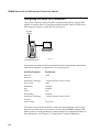
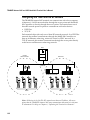
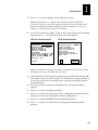
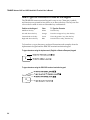
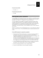
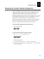
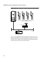
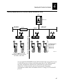
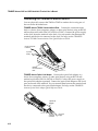
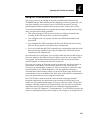
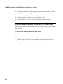
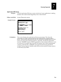
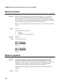
Configuring the T2425 and the RF Network
The TRAKKER Antares 2425 terminal can communicate with a host computer
in Intermec’s 2.4 GHz network either through the access points and the Model
200 Controller or directly through the access points. The terminal uses one of
these RF network protocol options to communicate with other devices:
•
UDP Plus
•
TCP/IP
Each terminal ships with only one of these RF network protocols. In a UDP Plus
network, the terminal communicates through the Model 200 Controller to a
host on an Ethernet, token ring, twinaxial, coaxial, or SDLC network. In a
TCP/IP network, the terminal communicates through the access point directly
to the host on an Ethernet or token ring network.
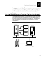
Host
TCP/IP
Direct Connect
UDP Plus
Ethernet
Access point
T2425
Model 200 Controller
Access point
T2425
242XU.193
Note: All devices in the 2.4 GHz RF network must have an IP address. All access
points that the TRAKKER Antares 2425 may communicate with must be in the same
IP subnetwork. For help, see Chapter 4, “Operating the Terminal in a Network.”
1-22
nuggetf
Getting Started
code39
1
To use RF communications on the T2425, you need to:
1. Configure the Model 200 Controller (UDP Plus) or host (TCP/IP).
2. Configure the access point.
3. Configure the network parameters on the terminal.
Each step is described in the next sections.
Caution
Make sure all components with antennas are at least 10 feet (3 meters) apart
when power is applied. Failure to comply could result in equipment damage.
Conseil
Assurez-vous que la distance entre tous les éléments avec antennes soit d'au
moins dix pieds (3 mètres) avant de faire la connexion avec l'alimentation
électrique, faute de quoi vous risquez d'endommager votre installation.
Configuring the Model 200 Controller, Host, and Access Points
To use your T2425 in Intermec’s 2.4 GHz UDP Plus RF network, you must first
install and configure the Model 200 Controller and the access points. For help,
see the Model 200 Controller System Manual (Part No. 063439) and your access
point user’s manual.
To use your T2425 in a TCP/IP direct connect 2.4 GHz RF network, you must
first install and configure the access points. For help, see your access point
user’s manual. You must also set up your host to communicate with the devices
in the RF network.
Note: You can use a T2425 running UDP Plus protocol and the Model 200 Controller
in a pass-through network. You establish a direct TCP/IP socket connection from the
T2425 to the host through the controller. For more information, see the Model 200
Controller System Manual.
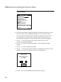
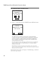
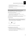
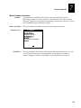
Configuring the T2425 Network Parameters
You need to set these network parameters to begin using RF communications:
UDP Plus Network Parameters
Network Parameter
Default Value
Network activate
Disabled
Controller IP address
0.0.0.0
Terminal IP address
0.0.0.0
RF domain
0
RF security identification (ID)
None (not set)
1-23
TRAKKER Antares 2420 and 2425 Hand-Held Terminal User’s Manual nuggetf
code39
TCP/IP Network Parameters
Network Parameter
Default Value
Network activate
Disabled
Host IP address
0.0.0.0
Terminal IP address
0.0.0.0
Network Port
23
RF domain
0
RF security identification (ID)
None (not set)
You use the TRAKKER Antares 2400 Menu System to set these parameters. For
a detailed definition of these parameters, see Chapter 4, “Operating the
Terminal in a Network.”
Note: If the terminal is on a different IP subnetwork from the Model 200 Controller or
host, you must also configure the default router and subnet mask. For help, see
Chapter 4, “Operating the Terminal in a Network.”
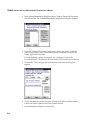
To set the network parameters
: V
1. From the Main Menu, press or to choose the Configuration Menu and
then press
. The Configuration Menu appears.
Note: If you are not in the TRAKKER Antares 2400 Menu System, press
to access the Main Menu.
T3 ,
CONFIGURATION
MENU
Symbologies Menu
Communications Menu
Terminal Menu
_` Select item
[Enter] Next screen
[F1] Help
[Esc] Exit
242XU.010
1-24
nuggetf
Getting Started
code39
V
2. Press to choose the Communications Menu and then press
Communications Menu appears.
1
. The
COMMUNICATIONS MENU
Primary Network
Advanced Network
Radio
Serial Port
_` Select item
[Enter] Next screen
[F1] Help
[Esc] Exit
242XU.011
3. Press
to choose the Primary Network command. The Primary Network
screen appears.
UDP Plus Primary Network
TCP/IP Primary Network
PRIMARY NETWORK
PRIMARY NETWORK
Activate:
Disabled
Controller IP Addr:
0.0.0.0
Terminal IP Address:
0.0.0.0
Activate:
Disabled
Host IP Addr:
0.0.0.0
Terminal IP Address:
0.0.0.0
OK
CANCEL
OK
CANCEL
242XU.186
W
4. In the Activate field, press to toggle the field and display the 2.4 GHz RF
option and activate radio frequency network communications. Press to
move to the next field.
V
5. In a UDP Plus network, you set the Controller IP Address. In a TCP/IP
network, you set the Host IP Address.
In the Controller IP Address or the Host IP Address field, type in the IP
address for the Model 200 Controller or host in your network.
The address field consists of four separate numbers. Each number in the
field is separated by a period and can be a number from 0 to 255. Type the
address in the format nnn.nnn.nnn.nnn and then press .
V
1-25
TRAKKER Antares 2420 and 2425 Hand-Held Terminal User’s Manual nuggetf
code39
For example, if your controller or host IP address is 192.100.100.2, type:
Note: The network cannot be activated if the first address segment in the IP
address is set to 0, 127, or a number greater than 223.
6. In the Terminal IP Address field, type in the terminal’s IP address. The IP
address must match the address that is set for the terminal on the controller
or host.
The address field consists of four separate numbers. Each number in the
field is separated by a period and can be a number from 0 to 255. Type the
address in the format nnn.nnn.nnn.nnn and then press .
V
For example, if your terminal IP address is 192.100.100.3, type:
Note: The network cannot be activated if the first address segment in the IP
address is set to 0, 127, or a number greater than 223.
to save the changes and exit the Primary Network screen.
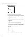
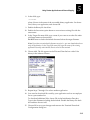
Press V to choose the Radio command and then press . The Radio
7. Press
8.
screen appears.
UDP Plus and TCP/IP Radio
RADIO
Domain: 00
Security ID:
(ID unchanged)
Wakeup on Broadcast:
No
Security ID
Override: No
Roam Flag:
Allowed
Transmit Mode: Auto
`
more
242XU.013
9. In the Domain field, type a number from 0 to 15 and then press
domain must match the number set on the access point.
V. The
V
10. In the Security ID field, type the RF security identification and then press .
The Security ID is case-sensitive and can be up to 20 characters long. It must
match the security ID set on the access point.
Note: If you have not changed the Security ID in the current session, the words,
(ID unchanged), display instead of the actual password. If you change the Security
ID, you see the actual password until you save the changes.
1-26
nuggetf
11. Press
Getting Started
code39
1
to save the changes and exit the Radio screen.
Note: If the terminal is on a different IP subnetwork from the Model 200
Controller or host, you must also configure the default router and subnet mask.
Choose the Advanced Network command to set these parameters. For help, see
Chapter 4, “Operating the Terminal in a Network.”
:
12. For TCP/IP networks, press to choose the Advanced Network command
and then press
. The Advanced Network screen appears.
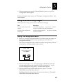
UDP Plus Advanced Network
TCP/IP Advanced Network
ADVANCED NETWORK
ADVANCED NETWORK
Loopback: Disabled
Network Port: 05555
Subnet Mask:
255.255.255.0
Default Router:
0.0.0.0
Controllr Connect Chk
Send Timer:0035 sec
Recv Timer:0060 sec
Retries: 07
Network Port: 00023
Subnet Mask:
255.255.255.0
Default Router:
0.0.0.0
TCP/IP Maximum
Transmit Timeout:
032 sec
` more
OK
CANCEL
242XU.181
Note: For UDP Plus networks, the Network Port default is 5555, which matches
the default value set on the Model 200 Controller.
V
13. In the Network Port field, type a number from 1 to 65535 and then press .
The default value is 23, which enables VT/ANSI Telnet communications. If
you are not using Telnet communications, enter the port number used by
your application.
?
Press ? to exit the Configuration Menu.
Press to choose Yes and save the new configuration in RAM. Once the
changes are saved, the terminal uses the new configuration.
Press ? to exit the TRAKKER Antares 2400 Menu System.
Press to choose Yes and store your changes permanently in flash
14. Press to exit the Communications Menu. The Configuration Menu
appears.
15.
16.
17.
18.
memory.
1-27
TRAKKER Antares 2420 and 2425 Hand-Held Terminal User’s Manual nuggetf
code39
Store Configuration Changes in Flash Memory Screen
Store configuration
changes in flash
memory?
(used when rebooting
the terminal)
Yes
No
CANCEL
242XU.054
19. Press
to choose OK and exit the TRAKKER Antares 2400 Menu System.
Exiting
TRAKKER Antares 2400
Menu System
OK
CANCEL
242XU.055
The T2425 will try to establish communications with the Model 200
Controller or the host. For terminal emulation applications in a UDP Plus
network, you need to configure the host name in the TE Configuration
menu to establish communications. For help, see the TRAKKER Antares
Terminal Emulation User’s Guide.
Once the terminal connects, the login or initial screen for your application
appears and the Connect icon stops blinking. You can begin using the
terminal to collect data.
Note: While the terminal is connecting to the controller or host, the terminal
ignores any input from the keypad or scanner. Wait until the terminal is connected
before you try to enter any data.
If the terminal will not connect, see Chapter 6, “Troubleshooting,” or the Model
200 Controller System Manual.
1-28
nuggetf
Getting Started
code39
1
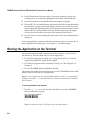
Verifying That the T2425 Is Communicating Correctly
Once you have configured the terminal, your T2425 is ready for operation. To
transmit and receive data, the T2425 must be communicating with the access
point and Model 200 Controller or host. Use these instructions to make sure the
T2425 is communicating correctly.
To verify that the T2425 is communicating correctly
1. If the terminal is not on, press
L to turn it on.
2. Look at the top line of the terminal’s screen. If the Connect icon (shown in
the illustration) appears and remains on solid, the terminal is
communicating with the access point. In a UDP Plus network, a solid
Connect icon also means that the terminal is communicating with the
controller. The terminal can send and receive data to the connected devices.
*
242XU.109
Note: The Connect icon is not instantaneously updated, but it does tell you the
communications status the last time data was sent or received from the terminal.
If you are having problems with network communications
•
If the Connect icon blinks or is not on, you need to check the network IP
addresses and configuration. Make sure the RF domain and RF security ID
on the terminal match the values that are set on the access point.
•
If the Radio icon (shown in the illustration) remains on solid, the Network
Activate command is disabled, or there is a problem with the radio card
and the radio is turned off.
242XU.116
Make sure the Network Activate command is enabled and all the network
parameters are set correctly. For help, follow the instructions for “Configuring
the T2425 and the RF Network” earlier in this chapter.
1-29
TRAKKER Antares 2420 and 2425 Hand-Held Terminal User’s Manual nuggetf
code39
Starting the Application and Using the Terminal
Your T2420 ships loaded with a sample application. Your T2425 ships loaded
with either the sample application, a terminal emulation application, or the
screen mapping application.
To start the application and use the terminal
L
1. Press
to turn on the terminal. The login or initial screen for your
application appears.
2. Check the four application screens shown next in the left column. Find the
application screen that matches the one on your terminal. Follow the
instructions on the right of the screen to use the T2420 or T2425.
Sample Application Screen
97/01/08
08:10:50
a. Use the sample application to scan bar code labels and test
the T2420 or T2425 keypad.
b. Connect the T2420 to a host computer using the TD2400
communications dock or the optical link adapter. For help,
see the accessory documentation.
242XU.167
c. Download your data collection application to the T2420 or
T2425 and run it. For help, see Chapter 5, “Using Custom
Applications and Screen Mapping.”
3270/5250 TE Sign-On Screen
*
Sign on
User..............
Password..........
Program/procedure.
Menu..............
Current Library...
a. Configure the terminal emulation application (if necessary).
For help, see the TRAKKER Antares Terminal Emulation
User’s Guide.
b. Login to a terminal emulation session.
c. Start using the T2425 to collect and transmit data.
242XU.166
VT/ANSI TE Login Screen
a. Configure the terminal emulation application (if necessary).
For help, see the TRAKKER Antares Terminal Emulation
User’s Guide.
*
<login:
b. Login to a terminal emulation session.
c. Start using the T2425 to collect and transmit data.
242XU.163
1-30
nuggetf
1
Getting Started
code39
Step 2: Using the Application (continued)
Screen Mapping Application
a. Download or request a template from the Model 200
Controller.
*
File Name:
b. Download or request a validation file from the controller.
c. Start using the T2425 to collect and transmit data.
242XU.168
Note: You can download applications to the T2425 either through the serial port or via
RF communications from the Model 200 Controller or host.
Turning the Terminal On and Off
The terminal’s Suspend/Resume key is the
the keypad, as shown in this illustration.
L key in the upper left corner of
L
When you press
to turn off
the terminal, the terminal does
not actually shut off, but goes
into a Suspend mode. This
mode is referred to as “off” in
the rest of this manual. In
Suspend mode, the terminal
continues to power all memory
and turns off the power to most
of the hardware.
L
Suspend/
Resume key
I/O
Enter
F6
F7
Enter
F10
F8
F9
F1
F2
F5
F3
F4
When you press
to turn on
the terminal, the terminal either
242XU.045
resumes exactly where it was
when you turned it off, or the
terminal boots and restarts your
application. Resume is
controlled through a parameter or command called Resume Execution. By
default, the terminal restarts your application. For help, see “Resume
Execution” in Chapter 9.
If you change the main battery pack while the terminal is turned off, the
terminal resumes or boots the next time the terminal is turned on. The backup
battery saves all memory while you change the main battery pack.
1-31
TRAKKER Antares 2420 and 2425 Hand-Held Terminal User’s Manual nuggetf
code39
Enabling Bar Code Symbologies
The TRAKKER Antares 2420 and 2425 terminals can decode several different
types of bar code symbologies. Each symbology, such as Code 39, uses a
different scheme for encoding data as bar code. You must configure the
terminal to decode the bar code symbology used in your bar code labels.
Only enable the bar code symbologies that you need to scan. For more
information about each symbology and the configuration options, see
Chapter 9, “Configuration Command Reference.”
The terminal can decode the bar code symbologies shown in the next table. You
can scan the bar code labels in the table to enable a symbology.
Note: Only three symbologies, Code 39, Code 128, and UPC/EAN, are enabled when
you unpack the terminal.
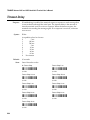
Bar Code Symbology
Enabled?
To Enable the Symbology
Codabar
No
Enable Standard Codabar, ABCD Start/Stop Code
*$+CD21*
*$+CD21*
Code 11
No
Enable Code 11 With Two Check Digits
*$+CG2*
*$+CG2*
Code 16K
No
Enable Standard Code 16K
*$+CP1*
*$+CP1*
Code 2 of 5
No
Enable Code 2 of 5, 3 Bar Start/Stop,
Label Length of 1
*$+CC001*
*$+CC001*
Interleaved 2 of 5
(I 2 of 5)
No
Enable I 2 of 5, Variable Length With a Check Digit
*$+CA99*
*$+CA99*
Note: You can enable either Code 2 of 5 or Interleaved 2 of 5. If you enable I 2 of 5,
Code 2 of 5 is automatically disabled and vice versa.
1-32
nuggetf
Getting Started
code39
1
Bar Code Symbology Table (continued)
Bar Code Symbology
Enabled?
To Enable the Symbology
Code 39
YES
Enable Code 39 Full ASCII With No Check Digit
*$+CB111*
*$+CB111*
Code 49
No
Enable Code 49
*$+CJ1*
*$+CJ1*
Code 93
No
Enable Code 93
*$+CF1*
*$+CF1*
Code 128
YES
Enable Standard Code 128
*$+CH1*
*$+CH1*
MSI
No
Enable MSI Without Check Digits
*$+CN10*
*$+CN10*
Plessey
No
Enable Plessey With Reverse Start Code
*$+CI10*
*$+CI10*
UPC/EAN
YES
Enable UPC-A/EAN-13, UPC-E, EAN-8
*$+CE1111111*
*$+CE1111111*
1-33
TRAKKER Antares 2420 and 2425 Hand-Held Terminal User’s Manual nuggetf
code39
What’s New on the TRAKKER Antares Terminals
The firmware on the TRAKKER Antares 2420 and 2425 terminals has been
updated and expanded:
TRAKKER Antares 2420 Terminal The T2420 is a programmable data collection
terminal that has a serial port to transmit data to and from a host via RS-232
serial communications. In the v2.20 firmware release, no additional features
were added for the T2420.
TRAKKER Antares 2425 Terminal The T2425 is a programmable data collection
terminal that you can use to run terminal emulation or custom applications.
With the v2.20 firmware release, you can use RF communications on the T2425
to communicate in either a TCP/IP direct connect network or a UDP Plus
network with the Model 200 Controller.
These new features for TRAKKER Antares terminals were added in firmware
versions 2.0, 2.10, and 2.11:
•
RS-232 serial communications on the T2420 and T2425
•
Multiple drives on the T2420 and T2425
•
Multiple applications stored on the T2420 and T2425
•
Western European alphanumeric keypad on the T2420 and T2425
These new features for TRAKKER Antares terminals were added in firmware
version 2.20:
•
TCP/IP radio frequency network protocol option to communicate in a
direct connect network (no Model 200 Controller).
•
Terminal emulation application enhancements that support auto-login
script files, TE Configuration menu security, TCP/IP direct connect
networks, and the ability to display international characters.
Using This Manual With Older Firmware Versions
If you have a TRAKKER Antares 2420 or 2425 with a firmware version lower
than 2.20, you can use this manual to learn how to use your terminal. However,
this manual describes features that are only available in TRAKKER Antares
firmware version 2.0 and higher. You may need to disregard the sections that
discuss these new features:
1-34
•
RS-232 serial port communications and configuration commands (v2.x)
•
Multiple drives and a configurable RAM drive (v2.x)
•
Multiple applications instead of a single terminal emulation or screen
mapping application and a file manager (v2.x)
nuggetf
Getting Started
code39
•
Western European alphanumeric keypad (v2.x)
•
TCP/IP direct connect network (v2.20)
1
Note: To check the firmware version number, choose About TRAKKER 2400 from the
Main Menu in the TRAKKER Antares 2400 Menu System.
Also, when you use the TRAKKER Antares 2400 Menu System, you will not see
all the menus and options shown in this manual. If you scan or enter a reader
or configuration command that is not available in version 2.0 or earlier, nothing
happens and it will not cause a problem.
There have been changes to the terminal emulation applications, so the
TRAKKER Antares Terminal Emulation User’s Guide explains features that may
not be available in the TE application you are using. You can use the
instructions in this manual and the TE user’s guide to run your terminal
emulation or screen mapping application, but will not be able to use new
features added in any later firmware release.
You can continue to use the older firmware version on the terminal or upgrade
to the latest firmware version, as described in the next section.
Ordering the Firmware Upgrade Kit
You can upgrade a TRAKKER Antares 2420 or 2425 terminal to use the latest
firmware version (2.x or higher) without making any hardware changes. There
are two upgrade kits:
Firmware Upgrade Kit
Part Number
Description
TRAKKER Antares TCP/IP
066814S
Order this kit for T2425s that
communicate in a TCP/IP
direct connect network or a
TCP/IP pass-through
network.
TRAKKER Antares UDP Plus
067119S
Order this kit for T2420s and
for T2425s that communicate
with a Model 200 Controller
in a UDP Plus network.
To order a firmware upgrade kit, contact your local Intermec service
representative. The kit comes with a utility and instructions to upgrade the
firmware on the terminal. Once you upgrade to the new firmware, you can use
all the features described in this manual.
1-35
TRAKKER Antares 2420 and 2425 Hand-Held Terminal User’s Manual nuggetf
code39
Where Do You Go From Here?
Now that your new TRAKKER Antares terminal is up and running, you can
use this manual to learn how to perform these tasks:
1-36
Task or Feature
See This Chapter
To learn how to use the terminal’s
keypad, screen, audio signals,
batteries, and scan module
Chapter 2, “Learning How to Use the
Terminal”
To learn how to change the terminal’s
configuration
Chapter 3, “Configuring the Terminal”
To add the terminal to your 2.4 GHz
RF or wired data collection system
and learn how to communicate with
other devices
Chapter 4, “Operating the Terminal in a
Network”
To learn how to download and run
custom applications or screen
mapping on your programmable
terminal
Chapter 5, “Using Custom Applications and
Screen Mapping”
To learn how to reset the terminal,
solve problems, and respond to error
messages
Chapter 6, “Troubleshooting”
To learn how to run diagnostics and
check the battery power remaining
Chapter 7, “Running Diagnostics”
2
Learning How to Use the Terminal
Co de
39
Nugget
Learning How to Use the Terminal
2
This chapter describes and explains how to use the terminal’s keypad, screen, audio
signals, serial port, batteries, memory and drives, and scan modules.
TRAKKER Antares Terminal Features
K
E
R
A
N
T
A
R
E
S
24
25
This chapter explains these features on the TRAKKER Antares 2420 and 2425
terminals:
T
R
A
K
CGA-compatible display
Keypad
1
0
4
2
7
5
3
F1
8
F2
6
F3
9
I/O
F4
F5
Scan module
J
Y
T
N
S
H
M
E
X
W
Ta
Z
U
V
P
b
K
Q
F
R
L
sc
A
G
B
Fn
L
I
C
O
Fn
R
D
E
E
nte
r
Antenna for
RF communications
Rechargeable
batteries
Serial port
242XU.030
Keypad There are five keypad options: an English alphanumeric keypad, a
Western European alphanumeric keypad, and three terminal emulation
keypads. The terminal ships with a keypad that supports the type of
application or terminal you ordered.
CGA-compatible display The terminal screen is a backlit LCD that is 16 lines by
20 characters. Depending on the application, you can use the viewport features
to move around a full 25 line by 80 character screen.
Audio signals The terminal and scan module have a beeper and internal
speakers to sound audio signals as you scan bar code labels and enter data.
Serial port The terminal has an optical serial port that you can use to transmit
data to and from another serial device via RS-232 serial communications.
Rechargeable batteries The terminal uses a rechargeable lithium-ion main
battery pack and a rechargeable NiCad backup battery to provide power.
Antenna for RF communications The T2425 uses radio frequency (RF) to
communicate with access points and the Model 200 Controller or host.
Memory The terminal has a total of 1MB RAM for system memory, and 2MB
flash memory to store firmware, configuration data, and custom applications.
Scan modules The terminal ships with a scan module to scan bar code data.
There are three scan module options: a standard range scan module, a long
range scan module, and a module for cabled scanners.
2-3
TRAKKER Antares 2420 and 2425 Hand-Held Terminal User’s Manual Co
de
39
Nugget
Using the Keypad
The TRAKKER Antares terminal has five keypad options:
•
English alphanumeric keypad
•
Western European alphanumeric keypad
•
IBM 3270 terminal emulation keypad
•
IBM 5250 terminal emulation keypad
•
VT100/220/320 and ANSI terminal emulation keypad
All five alphanumeric keypads have 56 keys. Although the keypad is smaller
than a desktop terminal keyboard, you use special keys on the T2420 and T2425
keypad to access all the keys and functions you need.
The Western European alphanumeric keypad has keys to support English and
Western European languages, such as French, German, Italian, Portuguese,
Spanish, and others. You use special keys and key sequences to access the
characters in each language.
A terminal emulation (TE) keypad comes with the TE option you ordered for
the T2425. Each TE keypad is similar to the standard alphanumeric keypad, but
contains additional keys that are available on an IBM 3270 keyboard, IBM 5250
keyboard, or VT/ANSI keyboard.
Note: The terminal emulation keypads are currently available in English only.
Finding the Special Keys
Before you use the terminal’s keypad, make sure you can find all of the
different types of keys on the keypad. You need to use these special keys on all
five keypad options.
The special keys that you use to type characters or perform functions are
explained in the next sections. You can use the Backlight key to turn on the
backlight, change the display contrast, and change the beep volume. For help,
see “Adjusting the Screen From the Keypad” later in this chapter.
2-4
Co de
39
Nugget
Learning How to Use the Terminal
2
Finding the Special Keys
Scan button
Backlight key
Suspend/Resume
key
I/O
Enter
Enter
F10
F6
F7
F1
Space/Backspace
key
F8
F2
F9
F3
&
*
7
8
$
%
9
4
5
6
!
@
#
1
2
3
>
BkSp
0
Fn L
.
Fn R
f
Function Left
key
Cursor keys
F5
F4
Enter
f
+
A
B
C
D
E
H
I
J
M
N
Enter key
-
Function Right
key
F
G
K
<
L
>
P
Q
,
U
R
W
Caps
Z
S
T
X
Y
/
.
V
O
\
?
Ctrl
Tab
Esc
242XU.004
Shift key
Control key
2-5
TRAKKER Antares 2420 and 2425 Hand-Held Terminal User’s Manual Co
de
39
Nugget
How to Type the Characters Printed on the Keypad
The TRAKKER Antares terminal keypad is easy to use. Characters, symbols,
and functions are printed in four places on or above the keys. The keys are also
color-coded to make it easier to remember key combinations.
Position on the Keypad
Color
To Type the Character
Middle of the key
White
Press the key.
Left side above the key
Orange
Press the orange
Centered above the key
Green
Right side above the key
Blue
key, then the key.
Press the green key, then the key.
Press the blue key, then the key.
To learn how to type characters, use these illustrations and examples from the
alphanumeric keypad and the IBM 5250 terminal emulation keypad.
To type characters using the alphanumeric (English or Western European) keypad
%
5
To type characters using the IBM 5250 terminal emulation keypad
Fld +
* Fld-
8
242XU.124
2-6
Co de
39
Nugget
Learning How to Use the Terminal
2
Using the Function Left/Right and Shift Keys
The TRAKKER Antares keypad does not have a physical key for every
character and function available. You use the Function Left (FnL), Function
Right (FnR), and Shift keys to access characters or perform functions that do not
have a physical key on the keypad. You also use the Shift key to type uppercase
alphabetic characters.
When you press , , or , the key is held in a buffer until you press another
key. The icon appears on the terminal’s screen to remind you that the key is
being held in the buffer. When you press another key, the key combination is
entered into the terminal and the icon disappears.
Shift
Function left
Function right
f
242XU.008
To flush the , , or key from the buffer without performing any action,
just press the key again. The icon disappears from the screen.
To use the FnL, FnR, and Shift keys
1. Press , , or . The Function Left, Function Right, or Shift icon appears
on the terminal’s screen.
For example, press
. The Shift icon appears on the terminal screen.
242XU.118
2. Press the second key. For example, press
to type the uppercase letter A.
The Shift icon disappears from the terminal’s screen.
2-7
TRAKKER Antares 2420 and 2425 Hand-Held Terminal User’s Manual Co
de
39
Nugget
Capitalizing All Characters
To type all alphabetic characters as uppercase letters, you can press
every letter you type, or you can enable the Caps Lock feature.
before
To enable Caps Lock
. The Function Left icon appears on the terminal’s screen.
Press 9 . The Caps Lock icon appears on the terminal’s screen.
Type an alphabetic character. The letter appears as an uppercase character
on the terminal’s screen. For example, press % to type an uppercase letter
1. Press
2.
3.
F. Caps Lock remains enabled until you disable it.
Login: F
242XU.046
To type a lowercase letter with Caps Lock enabled
•
Press and an alphabetic character. For example, press
lowercase letter f.
% to type a
To disable Caps Lock
. The Function Left icon appears on the terminal’s screen.
Press 9 . The Caps Lock icon disappears from the terminal’s screen.
1. Press
2.
3. Type an alphabetic character. The letter appears as a lowercase letter on the
terminal’s screen.
Note: You can also use the Keypad Caps Lock configuration command to enable or
disable Caps Lock on the terminal. For help, see “Keypad Caps Lock” in Chapter 9.
How to Use the Cursor Keys
You can press keys to move the cursor around an application screen. The
terminal’s cursor keys work the same as cursor keys on a regular keyboard. You
use the oval-shaped cursor key to move the cursor up, down, right, or left on
the screen.
2-8
Co de
39
Nugget
Learning How to Use the Terminal
2
Using the Cursor Keys
I/O
Cursor keys
Enter
F6
F7
F1
Enter
F2
F10
F9
F8
F3
F4
F5
242XU.042
To Use This Cursor Key
Arrow up
Arrow down
Arrow right
Arrow left
Press
:
V
W
;
Description
Moves the cursor up one row or line.
Moves the cursor down one row or line.
Moves the cursor one character to the right.
Moves the cursor one character to the left.
On the terminal emulation keypads, you can use the cursor keys to move
around the terminal’s screen if you are running a program or entering data in a
screen. For help, see the TRAKKER Antares Terminal Emulation User’s Guide.
Using the Western European Keypad
The programmable T2420 and T2425 (non-TE option) comes with either an
English or Western European alphanumeric keypad. The Western European
keypad supports English and most Western European languages, such as
French, German, Italian, Portuguese, Spanish, and others. You use the keypad
to enter all the characters printed on or above the keys. You can also use the
accent marks above the
through
keys to enter a character in a Western
European language. For example, you can type the character é.
Although the English alphanumeric keypad does not show all the characters
that are available on the Western European keypad, you can type the same
characters on either keypad. The next illustration shows the Western European
keypad.
2-9
TRAKKER Antares 2420 and 2425 Hand-Held Terminal User’s Manual Co
de
39
Nugget
Western European Keypad
Backlight key
Suspend/Resume
key
I/O
Enter
Enter
F10
F6
F7
F1
Accent marks
over F1 to F5
Space/Backspace
key
F3
8
9
4
5
6
1
2
3
Ins
Del
.
0
Fn R
f
Function Left
key
Enter
f
A
B
C
D
E
F
G
H
I
J
K
L
M
N
O
P
Q
R
S
T
U
V
W
X
Y
Enter key
Ctrl
Caps
Z
Cursor keys
F5
F4
7
Fn L
Function Right
key
F9
F8
F2
Tab
Esc
European
242XU.177
fuck you
Shift key
Control key
This section explains how to type characters that are not shown on the keypad.
Use the previous sections in this chapter to learn about typing characters that
are shown on the keypad; using the Function Left, Function Right, and Shift
keys; or capitalizing all characters.
2-10
Co de
39
Nugget
Learning How to Use the Terminal
2
To type characters with an accent mark
. The Function Right icon appears on the terminal’s screen.
Press the function key that the accent mark appears above. For example,
press to type the umlaut (¨).
1. Press
2.
To type
Press
ˆ (circumflex)
` (grave)
¨ (umlaut)
´ (acute)
~ (tilde)
A special Function Right icon appears with a third line to indicate that an
accent mark is stored in the keypad buffer.
f
242XU.115
To flush the accent mark from the keypad buffer without entering any key,
press
twice. The icons disappear from the terminal’s screen.
3. There are three types of characters you can enter:
•
To accent a lowercase character, press the character. For example, press
to type the ä character.
•
To accent an uppercase character, press the key. Next, press the
character you want to accent. For example, press and release the key,
and then press
to type the Ä character.
•
To type the accent mark by itself, press the
key.
The accented character or accent mark appears on the screen and the special
Function Right icon disappears.
If you try to accent a character and the resulting character is not supported on
the terminal, the plain (unaccented) character displays on the terminal screen.
For a complete list of the English and Western European characters available in
the terminal font, see Appendix C, “International Character Support.”
2-11
TRAKKER Antares 2420 and 2425 Hand-Held Terminal User’s Manual Co
de
39
Nugget
Quick Reference Keypad Chart
Use this keypad chart to enter any character or function on the alphanumeric
(English or Western European) keypad. For help about additional functions
that are available on a TE keypad, see the TRAKKER Antares Terminal Emulation
User’s Guide.
To Enter
0 to 9
a to z
A to Z
backlight on/off
backtab
beep volume
Bksp (backspace)
caps
contrast
ctrl
cursor down
cursor left
cursor right
cursor up
enter
escape
F1 to F5
F6 to F10
FnL (function left)
FnR (function right)
resume/suspend
shift
space
tab
viewport down
viewport end
2-12
Press the Key(s)
to to 9
to 9
9
V
;
W
:
@
?
to to L
To Enter
viewport home
viewport left
viewport right
viewport up
. (period)
, (comma)
: (colon)
; (semicolon)
=
+
- (dash)
/ (slash)
\ (backslash)
?
<
>
! (exclamation point)
@
#
$
%
&
* (asterisk)
(
)
_ (underline)
Press the Key(s)
or 6
5
%
+
(
"
'
7
3
1
/
or 0
!
Co de
39
Nugget
Learning How to Use the Terminal
2
Quick Reference Keypad Chart (continued)
To Enter
" (quotes)
‘ (apostrophe)
[
]
{
}
| (solid pipe)
¦ (broken pipe)
¿
¬ (not symbol)
½
¼
«
»
¤
£
¾
¶
§
° (degree)
• (dot)
¹ (superscript)
³ (superscript)
² (superscript)
ˆ (circumflex)
` (grave)
¨ (umlaut)
´ (acute)
~ (tilde)
Press the Key(s)
,
2
)
*
#
$
4
1
7
6
2
*
%
8
.
&
or or &
or To Enter
ç
Ç
β
µ
å
a
â
à
ä
á
ã
ê
è
ë
é
î
ì
ï
í
o
ô
ò
ö
ó
õ
û
ù
ü
ú
ÿ
Press the Key(s)
"
#
.
,
$
$
$
$
(
(
(
(
.
.
.
.
.
4
4
4
4
8
2-13
TRAKKER Antares 2420 and 2425 Hand-Held Terminal User’s Manual Co
de
39
Nugget
Quick Reference Keypad Chart (continued)
To Enter
ý
ñ
Å
Â
À
Ä
Á
Ã
Ê
È
Ë
É
Î
Ì
2-14
Press the Key(s)
8
(
!
$
$
$
$
(
(
To Enter
Ï
Í
Ñ
Ô
Ò
Ö
Ó
Õ
Û
Ù
Ü
Ú
Ý
Press the Key(s)
(
(
)
.
.
.
.
.
4
4
4
4
8
Co de
39
Nugget
Learning How to Use the Terminal
2
How to Use the Terminal’s Screen
You can use the TRAKKER Antares terminal’s screen to view data, run
applications, monitor the terminal’s status, and for many other functions. The
terminal’s black and white screen is 16 lines by 20 characters and is CGA
compatible.
Icons to monitor
the terminal status
f *•
First Name:
Address:
City:
CGA-compatible
display shows
16 lines by
20 characters
Age:
I/O
Fld Exit
Fld Exit
Backlight key
F6
F7
F1
F8
F2
Fld+
Home &
*
7
8
$
Dup %
PgLft
4
Fld- PgUp (
9
PgRt ^
6
FM @
1
PgDn #
2
BkSp
3
)
Ins
>
Del
0
Fn L
A
F16
F21
NL
U
-
G
;
F22
>
Stat
Q
,
Hm
V
F13
F18
"
F14 }
D
=
F23
?
R
¬ E-Eof
N
O
R
\ Help
R
S
. Clear
/ Attn
W
X
Ctrl
Tab
E
J
F24
’
F15
F19 [ F20
I
M
Caps
Z
{
H
L
P
| Sysrq
+
F17
C
`
K
<
F12
B
F
]
Enter
f
_
~ F11
:
.
Fn R
f
M3
F5
F4
5
!
End
F10
M2
M1 F9
F3
T
¢
E-Inp
Y
ErrRst
Esc
242XU.122
You can use these features of the screen:
•
In an application, use the terminal’s screen as a viewport to see a full-size
terminal screen of 25 lines by 80 characters.
•
Adjust the display’s backlight, contrast, and audio signal volume from the
keypad.
•
Use the terminal’s icons to monitor the status of special keys, battery power,
RF and network communications, and viewport movement.
Each screen feature is explained in the next sections.
Note: If you are using the terminal in a cold environment, the LCD display may
respond and display information more slowly than in a warm environment.
2-15
TRAKKER Antares 2420 and 2425 Hand-Held Terminal User’s Manual Co
de
39
Nugget
Using the Screen As a Viewport
The TRAKKER Antares terminal screen shows 16 lines by 20 characters of data
at one time. In terminal emulation (TE) or custom applications, the terminal’s
screen may show only part of each 25 line by 80 character screen that appears
on a full-size terminal. You can use the terminal screen as a viewport to move
around and see the entire 25 x 80 screen.
The viewport lets you view screens and enter data by showing the part of the
screen you are using. When you are using one of the Intermec TE applications,
the viewport automatically moves to the cursor when there is data entry from
the host computer or the terminal. You can configure the viewport for your TE
applications to:
•
Follow the cursor
•
Center the viewport around the cursor
For help on configuring the TE viewport options, see the TRAKKER Antares
Terminal Emulation User’s Guide.
The first time you turn the terminal on, it displays the upper left corner of a
full-size terminal screen. This is the viewport’s home position. A screen or
application that displays more than 16 lines by 20 characters of data at one time
has data in the unseen area of the screen. When you move the cursor or
viewport out of the home position (upper left corner), the Viewport icon
displays until the viewport is returned to its home position.
242XU.111
Adjusting the Screen From the Keypad
The Backlight key is one of the special features built into the terminal’s
keypad. You can use the Backlight key to:
•
Turn the backlight on and off on the terminal’s screen.
•
Adjust the display contrast.
•
Change the beep volume of the terminal’s audio signals.
For a detailed description of the backlight, contrast, and beep volume
commands, see Chapter 9, “Configuration Command Reference.”
Note: The Backlight key temporarily changes the backlight, contrast, or beep volume.
These changes are not saved permanently in flash memory.
2-16
Co de
39
Nugget
Learning How to Use the Terminal
2
Using the Backlight Key to Adjust the Screen
Backlight key
I/O
Enter
F6
F7
F1
Enter
F8
F2
F10
F9
F5
F3
F4
242XU.049
To turn the backlight on and off
•
Press . Turn the backlight on to more easily see the terminal’s screen in
dimly-lit environments.
The backlight stays on for the length of time set in the Display Backlight
Timeout command or until you press again. For more information about
the command, see “Display Backlight Timeout” in Chapter 9.
Note: You use the battery power at a faster rate with the backlight turned on.
To change the display contrast
•
Press
. Each time you press
level darker.
, it makes the display contrast one
There are eight contrast levels. If the contrast is at the darkest level and you
press , the contrast changes to the lightest contrast level.
To change the beep volume of the audio signals
•
To change the volume of the terminal’s audio signals, press
. Each
time you press , it makes the beep volume one level louder.
There are five beep volume levels including off. If the volume is at the loudest
level and you press
, the beep volume is turned off. If you press
again, the volume changes to the quietest level.
2-17
TRAKKER Antares 2420 and 2425 Hand-Held Terminal User’s Manual Co
de
39
Nugget
Understanding the Icons
You can use the terminal’s icons to monitor the status of special keys, battery
power, saving data to flash memory, RF and network communications, and
viewport movement. As you use the terminal, the icons are turned on and off in
the top line of the terminal screen to indicate the current status.
242XU.114
Ctrl This icon appears when you press
. The key is stored in the
keypad buffer until you press another key. When you press a
second key, the key combination is entered into the terminal and
the icon disappears.
242XU.118
242XU.117
9
Caps Lock This icon appears when you press
to enable the
Caps Lock feature and type all alphabetic characters as uppercase
letters. When you press
to disable Caps Lock, the icon
disappears.
9
f
242XU.112
Function Left This icon appears when you press . The key is
stored in the keypad buffer until you press another key. When you
press a second key, the key combination is entered into the terminal
and the icon disappears.
f
242XU.113
242XU.116
•
242XU.108
2-18
Shift This icon appears when you press . The key is stored in the
keypad buffer until you press another key. When you press a
second key, the key combination is entered into the terminal and
the icon disappears.
Function Right This icon appears when you press . The key is
stored in the keypad buffer until you press another key. When you
press a second key, the key combination is entered into the terminal
and the icon disappears.
Radio This icon appears when the Network Activate command is
disabled on a T2425, or there is a problem with the radio card and it
is turned off. The Radio icon disappears when the network is
enabled and the radio is on and transmitting. For help, see
Chapter 4, “Operating the Terminal in a Network.”
Data This icon contains a period. It appears on the screen when
data is buffered in the RF interface. The data is either waiting to be
transmitted to the Model 200 Controller or host, or received data
has not been accepted by the T2425’s application. When no data is
being buffered in the RF interface, the Data icon is off.
Co de
39
Nugget
Learning How to Use the Terminal
2
Understanding the Icons (continued)
Connect This icon contains an asterisk and tells you if the T2425 is
connected via RF communications to an access point and/or the
Model 200 Controller.
*
242XU.109
•
If the Connect icon is not displayed, the T2425 is not connected
to an access point. You may be out of range of an access point or
the terminal may not be configured correctly. If the Network
Activate command is disabled, the Connect icon is not
displayed, but the Radio icon does appear.
•
If the Connect icon blinks, the T2425 is trying to connect to the
controller or the access point. You may be out of range of an
access point, you may be about to go out of range of an access
point, or the access point may have recently been turned off. In
a UDP Plus network, the Connect icon also blinks when data
collection is not started on the controller.
•
If the Connect icon appears and remains on solid, the T2425 is
or was connected and communicating with the access point and
controller (UDP Plus) within the last 2 minutes.
The Connect icon is not instantaneously updated but does tell you
the communications status the last time data was sent or received
from the T2425. For help with network communications, see
Chapter 4, “Operating the Terminal in a Network.”
Battery This icon appears when one or both of the batteries have a
low power charge. The Battery icon appears with the terminal
turned on or off.
242XU.110
•
The Battery icon turns on and remains on and the terminal
beeps every 15 seconds when the main battery pack has about 5
to 45 minutes of power left.
•
The Battery icon blinks when the backup battery charge is low.
•
The Battery icon blinks and the terminal beeps every 15 seconds
when both batteries are low.
The Battery icon disappears when you replace or charge the main
battery pack, or charge the backup battery. For help, see “Learning
About the Terminal’s Batteries” later in this chapter.
242XU.111
Viewport This icon appears when you move the viewport out of
the upper left corner of the screen, which is the viewport’s home
position. When you move the viewport back to the home position,
the icon disappears.
2-19
TRAKKER Antares 2420 and 2425 Hand-Held Terminal User’s Manual Co
de
39
Nugget
Understanding the Terminal’s Audio Signals
The TRAKKER Antares terminal and scan module have a beeper and internal
speakers to sound audio signals or beep sequences as you use the terminal.
For example, you hear a low beep tone each time you enter or scan a valid
command.
You can change the beep volume to meet the needs of your working
environment. For example, use a quiet beep in a library or a loud beep in a
manufacturing plant. There are two ways to change the beep volume:
•
Use the Backlight key (press
) on the keypad. For help, see
“Adjusting the Screen From the Keypad” earlier in this chapter.
•
Use the Beep Volume command. For help, see “Beep Volume” in Chapter 9.
The next table explains the purpose of each beep sequence you may hear.
Beep Sequence
Description
Low beep
You entered a valid command or the data you entered
was stored.
High beep
You entered valid data, the terminal decoded a label, or
the terminal decoded the last row of a two-dimensional
symbology.
Three low beeps
You entered or scanned an invalid command or data.
Four low beeps
When you boot the terminal, you hear four low beeps
once the power-on self test (POST) has executed
successfully.
Low beep, high beep, low
beep, high beep
You hear this beep sequence when POST failed and did
not execute successfully. For help, see “Problems While
Operating the Terminal” in Chapter 6.
Click
When you press a key, the terminal sounds a click. You
can disable the keyclick. For help, see “Keypad Clicker”
in Chapter 9. The terminal also clicks while you are
scanning a two-dimensional symbology (Code 16K or
Code 49) bar code label.
Low beep (every 15
seconds)
The main battery pack is low. You need to replace or
recharge the battery pack. For help, see “Learning About
the Terminal’s Batteries,” later in this chapter.
Locating the Serial Port
Communications ports, also called COM ports, are locations from which data
can be passed into and out of the TRAKKER Antares terminal. You use serial
2-20
Co de
39
Nugget
Learning How to Use the Terminal
2
communications through a COM port, which means that data is transmitted
over a single line from one device to another.
You can use the terminal’s COM port to communicate with other devices.
T
R
A
K
K
E
R
AN
24
TA 2
R 5
ES
T2425
T
R
A
K
K
E
R
AN
24
TA 2
R 0
ES
T2420
F5
9
I/O
F4
6
F3
8
F2
1
0
4
2
7
5
3
F1
ter
F5
E
En
Fn
9
I/O
F4
F3
6
Fn
L
J
D
R
C
O
I
T
N
H
B
8
F2
A
Y
S
M
G
5
3
F1
L
7
F
2
4
X
R
P
Es
c
W
Q
K
Ta
b
0
V
1
U
ter
E
En
Fn
Fn
G
L
Z
J
D
R
C
O
I
X
R
P
Es
c
W
Q
K
Y
S
M
L
F
T
N
H
B
A
V
Ta
b
U
Z
242XU.183
COM1
serial port
You can communicate with other RS-232 devices, such as modems, PCs, and
printers, through COM1 by:
•
using a TRAKKER Antares TD2400 Communications Dock.
•
using a TRAKKER Antares Optical Link Adapter.
For help, see Chapter 4, “Operating the Terminal in a Network.”
2-21
TRAKKER Antares 2420 and 2425 Hand-Held Terminal User’s Manual Co
de
39
Nugget
Learning About the Terminal’s Batteries
There are two rechargeable batteries in the TRAKKER Antares terminal:
Main Battery Pack This lithium-ion battery provides the main power source to
operate the terminal.
Backup Battery This NiCad (Nickel-Cadmium) battery backs up all memory
and the real-time clock while you change the main battery pack.
Main Battery Pack
The main power source for the terminal is a lithium-ion battery pack. Follow
these tips to get the best battery performance and life possible:
•
You should always keep a charged main battery pack installed in the
terminal to maximize the backup battery’s life.
•
When you remove a battery pack, insert another charged battery pack in the
terminal.
•
Keep a spare charged battery pack available so you can continue to operate
the terminal without interruption.
•
If you use the terminal for extended periods of time in a sub-freezing
environment, you may need to change the battery pack more often.
•
If you have been using the terminal in a cold temperature environment and
need to replace or charge the battery pack, let the battery packs warm up for
a half hour before you charge them.
•
Store the battery chargers and spare battery packs in a warm (office)
environment to ensure the most efficient operation.
Removing and Installing the Main Battery Pack
The battery pack is the main power source for the terminal and it charges the
backup battery when required. If the main battery pack charge goes low, you
need to replace it or charge the battery pack as soon as possible.
There are two ways to find out if the battery pack is low:
•
The Battery icon appears and remains on solid on the top line of the screen,
and the terminal beeps once every 15 seconds.
•
Check the status of the battery pack using the Battery Status diagnostic test.
For help, see Chapter 7, “Running Diagnostics.”
If you have been using the terminal in a cold temperature environment and
need to replace or charge the battery pack, let the battery packs warm up for a
half hour before you charge them. Store the battery chargers and spare battery
packs in a warm (office) environment.
2-22
Co de
39
Nugget
Learning How to Use the Terminal
2
Caution
Removing the battery pack while the terminal is on may cause loss of data.
Conseil
Ne détachez pas le jeu de piles pendant que le lecteur est actif car cela pourrait
entraîner la perte de données.
To remove the battery pack
1. Press
L to turn off the terminal.
2. Open the battery door by pushing down on the battery door latch and
sliding it toward the bottom end of the terminal. Lift up the top edge of the
battery door to remove it.
Note: If you have a handstrap installed, stretch the handstrap’s elastic band to
allow the T-bar to slide out of the T-bar opening on the bottom end of the terminal.
Move the handstrap out of the way to open the battery door.
TOP
Battery door
latch
BOTTOM
242XU.079
2-23
TRAKKER Antares 2420 and 2425 Hand-Held Terminal User’s Manual Co
de
39
Nugget
3. Disconnect the battery pack from the connectors inside the bottom case by
sliding the battery pack toward the bottom end of the terminal.
242XU.103
ES
R
TA
T
R
A
K
K
E
R
AN
24
25
4. Tilt the terminal to one side and let the battery pack drop out of the
compartment into your hand. Continue with the next instructions to install
a charged battery pack.
F5
F4
I/O
9
F3
6
8
F2
F1
3
5
7
2
4
0
1
En
Fn
Fn
G
L
ter
E
J
D
R
C
O
I
B
H
F
L
P
Z
2-24
X
W
V
U
242XU.106
Y
S
R
Q
K
T
N
M
A
Ta
b
Es
c
Co de
39
Nugget
Learning How to Use the Terminal
2
To install the battery pack
1. Hold the battery pack with the flat side facing down toward the inside of
the battery compartment. The small arrow on the top of the battery pack
must point toward the top (screen) end of the terminal.
2. Place the battery pack into the upper (larger) half of the battery
compartment.
Connector end
Connector pin
(2 places)
Slots
242XU.082
3. Hook the slots on the bottom of the battery pack into the slots on the bottom
of the battery compartment.
4. Slide the battery pack toward the top end of the terminal until it fits and
locks into the connectors inside the bottom case. The battery pack must be
all of the way forward to close the battery door.
2-25
TRAKKER Antares 2420 and 2425 Hand-Held Terminal User’s Manual Co
de
39
Nugget
Installing the Battery Pack
242XU.102
5. If you are using an Intermec-labeled battery pack (Part No. 063278), make
sure you remove the rubber bumper from the inside of the battery door.
Otherwise, you will not be able to close the door.
If you are using a Sony-labeled battery pack, make sure the rubber bumper
is installed over the ridge near the wall on the inside of the battery door.
The rubber bumper on the battery door keeps the battery pack in place.
Rubber bumper
Wall
Ridge
Battery door
242XU.148
2-26
Co de
39
Nugget
Learning How to Use the Terminal
2
6. Hook the bottom edge of the battery door into the bottom case above the
backup battery compartment. Push the door down to close it over the
battery compartment. Push the battery door latch down and slide it toward
the top end of the terminal to lock the door in place.
Battery door
latch
242XU.088
Charging the Main Battery Pack
You can recharge the main battery pack using any of these TRAKKER Antares
accessories:
•
Battery charger
•
TD2400 communications dock connected to an external power supply
•
Optical link adapter connected to an external power supply
The fastest way to charge the battery pack is to use the battery charger. The
charger uses a charging method that maximizes battery life. For help about
charging battery packs, see the accessory quick reference guides.
After you install a charged battery pack in the terminal, you can use the Battery
Status diagnostic in the TRAKKER Antares 2400 Menu System to check the
charge status of the batteries. For help, see Chapter 7, “Running Diagnostics.”
Tip: Keep a spare charged main battery pack on hand to operate the terminal without
interruption.
2-27
TRAKKER Antares 2420 and 2425 Hand-Held Terminal User’s Manual Co
de
39
Nugget
Backup Battery
The backup battery is a NiCad battery that is designed to back up all memory
and the real-time clock while you remove a discharged main battery pack and
insert a charged battery pack. You can remove and replace the backup battery if
it will no longer hold a charge, or if the battery is dead.
The main battery pack charges the backup battery when required with the
terminal turned on or off. You should keep a charged main battery pack
installed in the terminal to maximize the backup battery’s life.
If you turn off the terminal and do not use it, the backup battery will provide
backup battery power for:
•
A maximum of 1 month if a fully-charged main battery pack is installed.
•
A maximum of 3 days if a main battery pack is not installed.
The backup battery power depends on how much power is left in the main
battery pack and the backup battery when you turn off the terminal. If the
backup battery is still providing backup power when you turn the terminal
back on, the terminal resumes exactly where it was when you turned it off, or
restarts your application.
If you plan to store the terminal for a long period of time, insert a fully charged
main battery pack to maximize battery life. Store the terminal in a warm (office)
area to make sure the backup battery continues to charge.
Note: If the Resume Execution command is allowed, the terminal will resume the
application when you turn on the terminal. Otherwise, the terminal boots and the
application restarts. For help, see “Resume Execution” in Chapter 9.
Charging the Backup Battery
The main battery pack charges the backup battery when required with the
terminal turned on or off. The terminal continuously monitors the backup
battery voltage level and charges the backup battery for a fixed duration of time
whenever the voltage level gets low. If the main battery pack is low or
discharged, it will not be able to charge the backup battery.
There are two ways to find out if the backup battery charge is low:
•
The Battery icon is blinking on the top line of the screen.
•
Check the status of the backup battery using the Battery Status diagnostic
test. For help, see Chapter 7, “Running Diagnostics.”
Note: The backup battery charger operates between 32°F and 104°F (0°C and 40°C). If
you are using the terminal in an environment that is outside this temperature range,
the backup battery will not charge. Move the terminal to a warmer environment to
charge the backup battery.
2-28
Co de
39
Nugget
Learning How to Use the Terminal
2
To fully charge a discharged backup battery
1. Install a fully charged main battery pack. For help, see “Removing and
Installing the Main Battery Pack” earlier in this chapter.
2. The main battery pack charges the backup battery. It will be fully charged
in approximately 18 hours. After you finish charging the backup battery,
the main battery pack still has most of its power remaining.
Note: The backup battery charges enough to operate the terminal within 20 minutes.
However, the backup battery will only provide limited backup power if it is not fully
charged.
Removing and Installing the Backup Battery
The backup battery should provide years of backup battery power and you will
seldom need to replace it. You can remove and replace the backup battery if it
will no longer hold a charge, or the battery is dead. Call your local Intermec
service representative to order a new backup battery.
Caution
When you replace the backup battery, all data stored in RAM is lost.
Conseil
Lors du remplacement de la batterie de secours, toutes les données stockées
dans la mémoire vive (RAM) sont perdues.
To remove the backup battery
1. Save your data or last transaction and exit your application.
2. Press
L to turn off the terminal.
3. Open the battery door by pushing down on the battery door latch and
sliding it toward the bottom end of the terminal. Lift up the top edge of the
battery door to remove it.
Note: If you have a handstrap installed, stretch the handstrap’s elastic band to
allow the T-bar to slide out of the T-bar opening on the bottom end of the terminal.
Move the handstrap out of the way to open the battery door.
2-29
TRAKKER Antares 2420 and 2425 Hand-Held Terminal User’s Manual Co
de
39
Nugget
Opening the Battery Door
TOP
Battery door
latch
BOTTOM
242XU.079
4. Remove the main battery pack. For help, see “Removing and Installing the
Main Battery Pack” earlier in this chapter.
5. Hold each of the backup battery connectors and gently pull to disconnect
the backup battery.
Battery wire
connectors
Backup
battery
242XU.086
6. Holding the visible end of the backup battery, slide the battery up and out
of the battery compartment. Continue with the next instructions to install
the new backup battery.
2-30
Co de
39
Nugget
Learning How to Use the Terminal
2
Removing the Backup Battery
Backup battery
Main battery
pack compartment
242XU.083
To install a backup battery
1. Slide the backup battery into the lower half of the battery compartment. The
wired end of the backup battery should be visible in the compartment.
Backup battery
Main battery
pack compartment
242XU.085
2-31
TRAKKER Antares 2420 and 2425 Hand-Held Terminal User’s Manual Co
de
39
Nugget
2. Find the two connectors in the backup battery compartment. One connector
is attached to the backup battery. The other connector is attached to the
terminal. Firmly push the two battery wire connectors together until they
lock. (The connectors are keyed so they cannot be connected incorrectly.)
Battery wire
connectors
Backup
battery
242XU.086
3. Gently fold and push the backup battery wires into the open area of the
backup battery compartment near the wall.
Folded wires
242XU.089
4. Install a fully charged main battery pack. For help, see “Removing and
Installing the Main Battery Pack” earlier in this chapter.
2-32
Co de
39
Nugget
Learning How to Use the Terminal
2
5. Hook the bottom edge of the battery door into the bottom case above the
backup battery compartment. Push the door down to close it over the
battery compartment. Push the battery door latch down and slide it toward
the top end of the terminal to lock the door in place.
Battery door
latch
242XU.088
The main battery pack charges the backup battery. The backup battery will be
fully charged in approximately 18 hours.
Note: The backup battery charges enough to operate the terminal within 20 minutes.
However, the backup battery will only provide limited backup power if it is not fully
charged.
Disposing of the NiCad Backup Battery
The materials used in the construction of the TRAKKER Antares NiCad backup
battery are recyclable. Intermec strongly urges that you recycle the backup
batteries when they reach the end of their useful lives. Additionally, the
Environmental Protection Agency has classified worn out or damaged NiCad
batteries or battery packs to be hazardous waste. Several states have passed
legislation that prohibits discarding these batteries into the municipal waste
stream.
If you have any question on how to recycle or dispose of the NiCad backup
batteries, contact your local, county, or state hazardous waste management
office.
2-33
TRAKKER Antares 2420 and 2425 Hand-Held Terminal User’s Manual Co
de
39
Nugget
Checking the Power Remaining in the Batteries
You can use the terminal’s diagnostics to check the power remaining in the
main battery pack, and to check the status of the backup battery. Use the
TRAKKER Antares 2400 Menu System to check the status of the batteries. For
help, see Chapter 7, “Running Diagnostics.”
Recognizing a Low or Discharged Battery
If you see the Battery icon or hear a beep every 15 seconds, the terminal is
indicating that the main battery pack or the backup battery power is almost
exhausted. Use this table to find out which battery is low or discharged.
Low Battery Warning
What You Need to Do
242XU.110
Main battery pack is low (5 to 45 minutes of
power left). Replace the battery pack with a spare
charged battery pack, charge the battery pack, or
attach an external power supply.
The Battery icon turns on and
stays on, and the terminal beeps
every 15 seconds.
242XU.126
Backup battery is low. Keep a charged main
battery pack installed in the terminal. Leave the
terminal off and let the battery pack charge the
backup battery. The backup battery charge will
be fully charged in approximately 18 hours.
The Battery icon blinks.
The main battery pack and the backup battery
charge are both low. Immediately, turn off the
terminal.
242XU.126
The Battery icon blinks and the
terminal beeps every 15 seconds.
2-34
Replace the main battery pack with a spare
charged battery pack. Leave the terminal off and
let the battery pack charge the backup battery.
The backup battery charge will be fully charged
in approximately 18 hours. If the Battery icon
continues to blink, you need to replace the
backup battery.
Co de
39
Nugget
Learning How to Use the Terminal
2
Managing Your Battery Power
To maximize the life of the terminal’s backup battery and main battery pack,
use these power management features.
Tip: Keep a spare charged main battery pack on hand to operate the terminal without
interruption. Always keep a charged or partially charged main battery pack in the
terminal.
Situation
Ways to Save Battery Power
You are not using the terminal
for 5 minutes or longer.
Press
to turn off the terminal and put it in
Suspend mode. Suspend mode maximizes the life of
the main battery pack’s power. Make sure the
battery pack is charged (not in a low battery state).
L
Or, use the Automatic Shutoff feature. Automatic
shutoff turns off the terminal (Suspend mode) when
there is no activity on the terminal for the length of
time you set. For help, see “Automatic Shutoff” in
Chapter 9.
L
You are operating the terminal
and the main battery pack
charge becomes low. (The
Battery icon remains on solid.)
Press
to put the terminal in Suspend mode.
Remove the main battery pack and insert another
charged battery pack. For help, see “Main Battery
Pack” earlier in this chapter.
You are operating the terminal
and the backup battery charge
becomes low. (The Battery icon
blinks.)
Press
to put the terminal in Suspend mode. Keep
a charged main battery pack installed in the
terminal. The battery pack will fully charge the
backup battery in approximately 18 hours.
L
Note: If you use the terminal in a cold temperature environment, battery life will be
reduced. For more information, see “Guidelines for Managing Batteries” in Chapter 6.
2-35
TRAKKER Antares 2420 and 2425 Hand-Held Terminal User’s Manual Co
de
39
Nugget
Using an External Power Supply
You can operate the terminal using an external power supply with the
following TRAKKER Antares accessories:
•
TD2400 communications dock connected to a power supply
•
Optical link adapter connected to a power supply
You can use the external power supply to operate the terminal and to charge
the terminal’s batteries at the same time. For help, see the accessory quick
reference guides.
25
RES
24
ANTA
KER
S
RE
TA
F2
8
3
F1
7
5
I/O
2
F5
F4
4
0
F3
9
r
te
J
R
D
8
E
En
F2
C
I
S
Y
N
H
B
M
Es
W
K
Q
F
R
L
2
Ta
Z
U
0
V
P
b
1
X
c
A
3
T
L
Fn
5
4
O
Fn
6
7
G
F1
1
To power
supply
6
F3
9
I/O
F4
F5
T
R
A
K
K
E
R
AN
24
20
TRAK
r
Ente
E
Fn R
D
Fn L
C
J
I
B
O
H
A
N
G
T
M
F
L
S
Y
R
K
X
Q
Esc
W
P
V
Tab
U
24
25
Z
To power
supply
242XU.186
2-36
Co de
39
Nugget
Learning How to Use the Terminal
2
Defining the Terminal’s Memory and Drives
The TRAKKER Antares 2420 and 2425 terminals come with the following
memory and drives:
750K flash
drive
750K flash
drive
Drive C
Drive C
256K
configurable
RAM drive
256K configurable
RAM drive
Optional 2MB or
4MB extended
storage drive
Drive E
Drive E
Drive G
242XU.180
TRAKKER Antares 2425 Terminal
TRAKKER Antares 2420 Terminal
Drive C is a 750K flash drive on the T2420 and T2425. You can store up to 32 files
on drive C. Applications must be stored on drive C.
Drive E is a configurable RAM drive (up to 256K). By default, the RAM drive is
not configured and the memory is available for programmable (Malloc)
memory allocations. To configure the RAM drive, see “RAM Drive Size” in
Chapter 9. You can store up to 32 files on drive E. The contents of the RAM
drive are erased when you boot or reset the terminal, or change the backup
battery.
Drive G is an optional 2MB or 4MB extended storage drive that is only available
on the T2420. You can store up to 32 files on drive G. Use this drive to store
large lookup tables and data files.
Note: On each drive, filenames are customer defined using eight characters with a
three-character extension.
On the TRAKKER Antares terminals, applications are customer defined. You
have 512K total RAM for the application execution space. If the RAM drive is
configured, your application execution space is reduced by the amount of the
RAM drive.
Application
execution space
+
Drive E
=
512K RAM
Note: The remaining RAM is the Malloc/free memory pool.
2-37
TRAKKER Antares 2420 and 2425 Hand-Held Terminal User’s Manual Co
de
39
Nugget
Using the Scan Module
You use the scan module accessories with the TRAKKER Antares 2420 and 2425
terminals to scan and enter bar code data. The terminal decodes the bar code
label and enters the data or command you scanned.
There are three types of scan modules available:
•
Module for cabled scanners
•
Standard range scan module
•
Long range scan module
Note: See your Intermec sales representative for information about the availability of
the long range scan module
The module for cabled scanners has a port to attach a wand, laser scanner, or
CCD scanner. The standard range scan module has an integrated laser scanner.
The long range scan module has an integrated laser scanner with a spotting
beam. For more information about your scan module, see the instruction sheet
that ships with the module.
You can scan bar code labels with the integrated standard or long range scan
module, or with the scanner device that is connected to the module for cabled
scanners.
Important: You must have a scan module attached to use the terminal.
When you unpack the terminal and begin using it, only three bar code
symbologies are enabled: Code 39, Code 128, and UPC/EAN. If you are using
bar code labels that are encoded in another symbology, you need to enable that
symbology on the terminal. For help, see “Enabling Bar Code Symbologies” in
Chapter 1, or find the symbology in Chapter 9, “Configuration Command
Reference.”
Note: The Scan button on the terminal keypad does not activate the scanner device
connected to the module for cabled scanners.
The next sections cover these topics:
2-38
•
Installing a Scan Module
•
Using the Standard Range Scan Module
•
Scanning Options
Co de
39
Nugget
Learning How to Use the Terminal
2
Installing a Scan Module
To use the terminal, you must have a scan module installed on the terminal.
The scan module is installed at the Intermec factory.
You may want to change the scan module and install another type of scan
module on the terminal. Use these instructions to remove and install the scan
module.
Note: Observe all static electricity precautions before installing a module.
To install a scan module
1. Make sure the terminal is off and then lay it face down on a clean and
sturdy work surface.
2. Use a Phillips screwdriver and remove the three screws that secure the scan
module to the terminal.
3. Remove the existing scan module from the terminal.
4. To install the module, align the module guides with the guides on the
terminal. Gently press down on the module to seat the connector guide
pins and the module connector into the connector on the terminal.
Screw
Screw
Screw
Scan module
Scan module
guide (2 places)
Terminal guide
(2 places)
242XU.040
2-39
TRAKKER Antares 2420 and 2425 Hand-Held Terminal User’s Manual Co
de
39
Nugget
Note: The module guide pins and connector should fit easily into the connector on
the terminal. DO NOT force the module into the connector or you may damage the
module connector, the terminal connector, or both.
5. Insert the three screws into the module and tighten them to secure the scan
module to the terminal.
Using the Standard Range Scan Module
The standard range laser scan module emits a beam of laser light that is visible
on a bar code label as you scan it. The terminal decodes the bar code label and
enters the data or command you scanned.
This section only explains the standard range scan module. For help using the
long range scan module or the module for cabled scanners, see the instruction
sheet that ships with the module.
Warning
Do not look directly into the window area or at a reflection of the laser beam
while the laser is scanning. Long-term exposure to the laser beam can damage
your vision.
Avertissement
Ne regardez pas directement la réflexion d’un rayon laser ou dans la fenêtre du
laser lorsque celui-ci est en opération. Si vous regardez trop longtemps un
rayon laser, cela peut endommager votre vue.
To scan a bar code label with the standard range scan module
1. Press
L to turn on the terminal.
2. Hold the terminal at a slight angle a few inches from the bar code label. The
laser scan window in the scan module must be pointing toward the label.
3. Push the Scan button on the keypad. Direct the beam so that it falls across
all bars in the bar code label. After the terminal successfully reads the label,
you hear a high beep. The scanner stays on or turns off depending on the
scanning options you have configured.
When the scanner laser beam is on, both scanner light emitting diodes
(LEDs) at the top of the keypad are lit in a yellow color. Once the bar code
label is scanned successfully, the LEDs are lit in a green color. The LEDs
turn off after 2 seconds unless you start scanning another label.
Note: Some of the scanning options described in the next section allow you to scan
multiple bar code labels without having to press the Scan button each time. The
yellow LEDs stay lit any time the scanner laser beam is on.
2-40
Co de
39
Nugget
Learning How to Use the Terminal
2
4. Release the Scan button.
*B
02
41
8*
T
R
A
K
K
E
R
24
A
N
T
A
R
E
S
25
Scanner LED
indicators (2 places)
F5
9
I/O
F4
6
F3
8
F2
1
0
4
2
7
5
3
F1
er
Ent
Fn
Fn
L
E
J
D
R
C
A
O
I
L
X
R
P
Esc
W
Q
K
Y
S
M
G
F
T
N
H
B
V
b
Ta
U
Z
Scan button
242XU.034
To successfully read a bar code label, the laser beam in the scan module must
see all the bars in a label and a “quiet zone” at each end of the label. A quiet
zone is a clean, non-printed space.
*NANCY*
Quiet zone before and
after bar code
242XU.076
With the standard range scan module, you will have the best success if you
hold the terminal so that the horizontal reading angle is near zero and the
vertical reading angle is near 20 degrees. To get the best scan angle, hold the
terminal so that the scan module is pointing toward bar code label. Tilt the
terminal up or down slightly (20 degrees). You can also watch the laser beam.
The laser beam becomes the brightest at the best scan angle.
2-41
TRAKKER Antares 2420 and 2425 Hand-Held Terminal User’s Manual Co
de
39
Nugget
Optimum scan angles vary with the type and print quality of the bar code label,
the distance of the scanner from the label, and the lighting in the area.
Note: You should not scan the bar code label “straight on.” In a 2-degree conical “dead
zone” directly above the label, the laser beam may reflect back into the scanner window
and prevent the terminal from reading the label. At certain angles and straight on, you
may not see the laser beam.
Scanning Options
You can set several configuration command parameters to configure the laser
scanner to meet your needs. There are several ways to set the scanner
commands on the terminal. For help, see Chapter 3, “Configuring the
Terminal.” For help using the scanner configuration commands, see Chapter 9,
“Configuration Command Reference.”
The parameters available are:
Decode Security Defines the security level to use when decoding bar codes.
When you select a lower decode security level, the terminal can decode bar
codes with poorer print quality.
Scan Ahead Allows you to scan a number of bar code labels at one time. The
labels are held in a stack until the terminal can process the data.
Scanner Mode Defines how the scanner operates when you press the Scan
button or activate a cabled laser scanner. In One-Shot mode, the laser turns on
and stays on until you release the button or scanner trigger, or a label is
decoded. In Automatic mode, you can continuously scan bar code labels
without having to release the button or scanner trigger between labels.
Scanner Redundancy Defines the number of scans (voting) the scanner takes of
the same label. When set, voting requires the terminal to decode the same bar
code label multiple times during a single scanner event, and compare the
decoded information for a match before signaling a good read.
Scanner Selection Identifies the type of scanner you have connected to the
TRAKKER Antares terminal module for cabled scanners. The terminal can
optimize the scanning performance by using the scanner you define in this
command. If you have a long range scan module, Scanner Selection allows you
to configure the spotting beam.
Scanner Timeout Defines the maximum length of time the scanner stays on
each time you press the Scan button or activate the cabled laser scanner.
Scanner Trigger Allows you to set the triggering to level or edge triggering.
With level triggering, you activate the scanner and the laser turns on and stays
on until you release the Scan button or the trigger on a cabled scanner. In edge
triggering, you activate the scanner and the laser turns on and stays on until
you activate the scanner a second time, or the scanner timeout turns it off.
2-42
3
Configuring the Terminal
Co de 39
Nugget
Configuring the Terminal
3
This chapter explains how to configure the terminal, discusses the terminal’s
configuration parameters, and tells you how to restore the default configuration. The
table at the end of the chapter lists all the configuration parameters and their options.
How to Configure the Terminal
You can configure the TRAKKER Antares 2420 and 2425 terminals by using
either of the methods described in detail in this chapter:
Using the TRAKKER Antares 2400 Menu System With menus and screens, the
TRAKKER Antares 2400 Menu System lets you view the current configuration
and modify configuration parameters.
Configuring the terminal by scanning bar codes You can change the terminal’s
current configuration by scanning Code 39 or Code 93 bar code labels that
contain configuration commands. This method is a fast, easy way to change the
terminal’s configuration. You can scan the bar code labels in this manual, or
you can create your own bar code labels.
Note: You can also configure the terminal from a remote device. You can configure the
T2425 from the Model 200 Controller or from an application on the host. You can
configure the T2420 or T2425 by sending commands from an application through the
serial port. For help, see Chapter 4, “Operating the Terminal in a Network.”
Learning About Configuration Parameters
You can customize many operating characteristics of the TRAKKER Antares
2420 and 2425 terminals, such as the volume of its audio signals and the bar
code symbologies it decodes. These characteristics are controlled by
configuration parameters. The values you set for the configuration parameters
determine how the terminal operates.
By customizing the terminal’s configuration, you can set up the terminal to
operate easily and efficiently within your data collection system.
Note: To learn the purpose and syntax of each configuration parameter or command,
see Chapter 9, “Configuration Command Reference.”
The configuration parameters can be organized into three groups, which are
discussed in the next sections: bar code symbologies, communications, and
general operation. When you configure the terminal, you are performing one or
more of these tasks:
•
Choosing the Symbologies the Terminal Decodes
•
Specifying How the Terminal Will Communicate
•
Controlling How the Terminal Will Operate
3-3
TRAKKER Antares 2420 and 2425 Hand-Held Terminal User’s Manual Co
de 39
Nugget
Choosing the Symbologies the Terminal Decodes
This list contains all the bar code symbologies the terminal can decode:
•
Codabar
•
Code 2 of 5
•
Interleaved 2 of 5 (I 2 of 5)
•
Code 11
•
Code 39
•
MSI
•
Code 128
•
Code 49
•
Plessey
•
Code 16K
•
Code 93
•
UPC/EAN
When the terminal ships, only these three symbologies are enabled:
•
Code 39
•
Code 128
•
UPC/EAN
If you are using one of the other symbologies to encode your bar code labels,
you need to configure the terminal and enable the symbology. To quickly
enable symbologies, see “Enabling Bar Code Symbologies” in Chapter 1.
To ensure that the terminal can operate quickly and efficiently, you should
enable only the bar code symbologies that you are going to scan. When you
enable each bar code symbology, you may need to set a check digit, the length
of the bar code label, or other options. For help, see the bar code symbology in
Chapter 9, “Configuration Command Reference.”
Specifying How the Terminal Will Communicate
The T2420 uses RS-232 serial communications to send data to and from another
serial device. The T2425 uses radio frequency (RF) communications to
communicate with other devices in Intermec’s 2.4 GHz RF network. You can
also use the T2425’s serial port to send and receive data. Before you can use the
terminal in your wired or RF network, you must configure the serial port
and/or network parameters.
On the T2425, you must set the RF network parameters, radio parameters, and
address information before the T2425 can communicate with other devices in
your 2.4 GHz RF network. For example, you must set the Terminal IP Address
so the T2425 can transmit data to and receive data from other network devices.
To learn how to configure the terminal to fit into your wired or 2.4 GHz RF
network, see Chapter 4, “Operating the Terminal in a Network.”
3-4
Co de 39
Nugget
Configuring the Terminal
3
Controlling How the Terminal Will Operate
The operating parameters let you adjust the way the terminal operates. By
customizing the operating parameters, you can
•
set the terminal to automatically shut off after a specified length of time.
•
set the terminal to resume applications or restart applications.
•
modify data transactions by appending the time.
•
modify bar code data by using preambles and postambles.
•
enable or disable specific reader commands.
•
configure a RAM drive.
•
change the volume of the audio signals (beeper and keypad clicker).
•
control the display contrast, backlight timeout, and font size.
•
enable or disable the keypad clicker and keypad caps lock.
•
customize the way the scan module operates by selecting scan ahead data
buffering, type of scanner device, decode security level, scanner timeout
value, and trigger modes.
3-5
TRAKKER Antares 2420 and 2425 Hand-Held Terminal User’s Manual Co
de 39
Nugget
Configuring the Terminal With the Menu System
The TRAKKER Antares 2400 Menu System is a menu-driven application that
lets you configure the terminal, manage files, view system information, and run
diagnostics. You can access the TRAKKER Antares 2400 Menu System while
running any application.
To access the TRAKKER Antares 2400 Menu System
•
T 3 , or scan this bar code:
Note: You must press the T (Left Enter) key in this key sequence.
Press
Enter Test and Service Mode
*..-.*
*..-.*
The Main Menu appears, displaying four menu options.
Configuration Menu Choose the Configuration
Menu to configure bar code symbologies,
network and communications parameters,
serial port parameters, and the terminal’s
operating characteristics.
Diagnostics Menu Choose the Diagnostics
Menu to run hardware, software, or system
diagnostics to help analyze and fix problems
on the terminal. You can also view
information about batteries and the system.
For help, see Chapter 7, “Running
Diagnostics.”
242XU.001
System Menu Choose the System Menu to manage files, load the default
configuration, set the time and date, store the terminal’s configuration in flash
memory, and upgrade the firmware.
About TRAKKER 2400 Choose this option to see the part number, firmware
version, and RF protocol (UDP Plus or TCP/IP) loaded on the terminal. You
may need this information if you are working a problem with an Intermec
representative.
3-6
Co de 39
Nugget
Configuring the Terminal
3
The TRAKKER Antares 2400 Menu System at a Glance
MAIN MENU
CONFIGURATION
Configuration Menu
Diagnostics Menu
System Menu
About TRAKKER 2400
MENU
Symbologies Menu
Communications Menu
Terminal Menu
SYMBOLOGIES
SYSTEM
MENU
*Code 39
Codabar
Code 11
Code 49
Code 93
*Code 128
Code 16K
2of5 / I 2of5
MSI
Plessey
*UPC / EAN
MENU
File Manager
Load Default Values
Set Time and Date
Store Configuration
Upgrade Firmware
CONFIGURATION
MENU
Symbologies Menu
Communications Menu
Terminal Menu
DIAGNOSTICS MENU
COMMUNICATIONS
Software Diagnosticss
Hardware Diagnostics
System Diagnostics
Serial
MENU
Port
T2420
SOFTWARE DIAGNOSTICS
Error Logger
Application Events
Task Status
Clear Task Profiles
HARDWARE DIAGNOSTICS
Hardware Config
Battery Status
Display Test
Keypad Test
Main Board Menu
Radio Test
Serial Loop Back
Scanner Test
SYSTEM DIAGNOSTICS
Subsystem Versions
Access Point
Suspend-Resume Test
App Efficiency
Serial Port Test
Malloc Info Menu
COMMUNICATIONS
T2425
CONFIGURATION
MENU
Primary Network
Advanced Network
Radio
Serial Port
MENU
Symbologies Menu
Communications Menu
Terminal Menu
TERMINAL MENU
Append Time
Beeper
Display
Keypad
Power Management
Preamble/Postamble
RAM Drive
Reader Command Menu
Scanner
242XU.178
3-7
TRAKKER Antares 2420 and 2425 Hand-Held Terminal User’s Manual Co
de 39
Nugget
Exploring the Configuration and System Menus
When you access the TRAKKER Antares 2400 Menu System, the Main Menu
appears. You use the Configuration Menu and the System Menu to configure
the terminal.
The Configuration Menu contains these commands:
CONFIGURATION
MENU
Symbologies Menu
Communications Menu
Terminal Menu
_` Select item
[Enter] Next screen
[F1] Help
[Esc] Exit
242XU.010
Symbologies Menu Choose the Symbologies Menu to configure and activate
the bar code symbologies the terminal can decode. An asterisk (*) on the
Symbologies Menu indicates that the symbology is active. For help, see
“Choosing the Symbologies the Terminal Decodes” earlier in this chapter.
Communications Menu Choose the Communications menu to configure the
primary network parameters, the advanced network parameters, the radio
parameters, or the serial port parameters. On a T2420, only the serial port
option is visible since the terminal has no radio. For help, see Chapter 4,
“Operating the Terminal in a Network.”
Terminal Menu Choose the Terminal Menu to configure the way the terminal,
keypad, scanner, or screen operate. For help, see “Controlling How the
Terminal Will Operate” earlier in this chapter.
The System Menu contains these commands:
SYSTEM MENU
File Manager
Load Default Values
Set Time and Date
Store Configuration
Upgrade Firmware
_` Select item
[Enter] Next screen
[F1] Help
[Esc] Exit
242XU.051
3-8
Co de 39
Nugget
Configuring the Terminal
3
File Manager Lets you manage the files on each drive. You can run an
application from drive C, delete a file from any drive, or rename a file on any
drive. For help using the File Manager, see “Running the Application on the
Terminal” in Chapter 5.
Load Default Values Lets you load the default configuration values. For help,
see “Restoring the Terminal’s Default Configuration” later in this chapter.
Set Time and Date Lets you set the current time and date. For help, see “Setting
the Time and Date” in Chapter 1.
Store Configuration Stores the current configuration in flash memory, including
any changes you have made in the menu system. When you exit the TRAKKER
Antares 2400 Menu System, you will also be prompted to save your changes.
For help, see “Exiting the TRAKKER Antares 2400 Menu System” later in this
chapter.
Upgrade Firmware Lets you upgrade the system firmware on the terminal. For
help, see “Upgrading the Firmware” later in this chapter.
You can use the keystrokes described next to move around in the TRAKKER
Antares 2400 Menu System, or you can scan bar code labels. For a list of bar
code labels, see the “Full ASCII Bar Code Chart” in Appendix B.
Selecting Menus and Commands
: V
U
VV
T
Press or to choose a menu name from the Main Menu. Then press
, ,
or to display the commands in the selected menu. In this example, you press
to display the System Menu:
Note: In the menu system, the
MAIN
MENU
, T , and U keys all work the same way.
SYSTEM
MENU
Configuration Menu
Diagnostics Menu
System Menu
About TRAKKER 2400
File Manager
Load Default Values
Set Time and Date
Store Configuration
Upgrade Firmware
_` Select item
[Enter] Next screen
[F1] Help
[Esc] Exit
_` Select item
[Enter] Next screen
[F1] Help
[Esc] Exit
242XU.058
: V
Press or to choose a command or option from a menu, and then press
to execute the command or option.
Note: You can press
help screen.
at any time to display an online help screen. Press ? to exit a
3-9
TRAKKER Antares 2420 and 2425 Hand-Held Terminal User’s Manual Co
de 39
Nugget
Filling In Fields and Marking Check Boxes
Screens list the options for each configuration parameter, diagnostic, or system
option. Below each option name is either a toggle field or an entry field:
; , W , or to view the options for that field.
• In an entry field, you type a value into the field. To edit the data in an entry
field, use the ; , W , , or keys. You can also use the Delete ( )
and Insert ( ) keys to edit an entry field.
For example, the Code 49/Code 16K screen has toggle and entry fields. The
Code 49 field is a toggle field. Press to toggle between Enabled and
•
In a toggle field, you press
Disabled. The Function Codes field for F1, F2, and F3 are entry fields. You type
a value into the field for each function code.
CODE
Code
49
49:
/
CODE
16K
Enabled
Code 49
Function Codes:
F1:
F2:
\x0D\x0A
F3:
Code 16K:
Standard
OK
CANCEL
242XU.052
Some screens contain check boxes. Check boxes are used when more than one
option can be selected at one time.
To mark or clear check boxes
•
Press
. For example, to disable the Backlight reader command, choose
the Backlight check box and press
to clear the check box.
READER COMMAND MENU
[Space] to enable or
disable a command
[X] Abort Program
[X] Backlight
[X] Backspace
[X] Change Config
[X] Clear
[X] Default Config
[X] Delete File
[X] Enter Accum
[X] Exit Accum
[X] List Files
[X]
[X]
[X]
[X]
[X]
[X]
[X]
[X]
[X]
OK
Multi-Read
Receive File
Rename File
Reset
Run Program
Scanner On
Scanner Off
Test & Service
Transmit File
CANCEL
more
_
242XU.053
3-10
Co de 39
Nugget
Configuring the Terminal
3
To move to the next field
•
Press
V or .
To move to the previous field
•
Press
:.
Entering ASCII Control Characters
You can include ASCII control characters in a postamble or preamble by using
the TRAKKER Antares 2400 Menu System. For a definition of the postamble or
preamble, see Chapter 9, “Configuration Command Reference.”
You can configure the postamble or preamble to characters from the full or
extended ASCII character sets. For example, the Field Exit code (Ü) for 5250
terminal emulation is an extended ASCII character that is often configured as
the postamble. For a list of the full and extended ASCII characters, see
Appendix B, “Full ASCII Charts,” or the TRAKKER Antares Terminal Emulation
User’s Guide.
Note: For more help on using the 5250 Field Exit code, see “Auto-Advancing Through
Fields on 5250 TE Screens” in the TRAKKER Antares Terminal Emulation User’s
Guide.
To enter ASCII characters for a preamble or postamble
1. Decide which ASCII control character you want to set for the preamble or
postamble. Look up the control character in the Full ASCII Table in
Appendix B and find the two-digit hexadecimal number. For example, ETX
in the Full ASCII Table is the hexadecimal value 03.
To enter an extended ASCII character, look up the hexadecimal number for
the character in the “TRAKKER Antares Terminal Font Set” in Appendix C.
For example, 9A is the hexadecimal value for Ü, the 5250 Field Exit code.
2. Use the TRAKKER Antares 2400 Menu System to configure a preamble or
postamble. From the Main Menu, choose Configuration Menu.
3. From the Configuration Menu, choose Terminal Menu.
4. From the Terminal Menu, choose Preamble/Postamble.
3-11
TRAKKER Antares 2420 and 2425 Hand-Held Terminal User’s Manual Co
de 39
Nugget
Configuring the Preamble and Postamble
PREAMBLE
/
POSTAMBLE
Preamble:
abc
Postamble:
\x0D\x0A
OK
CANCEL
242XU.057
5. Move the cursor to the field for the preamble or postamble.
6. Type the control character, extended ASCII character, or escape character
sequence in the preamble or postamble field.
•
To type a control character or extended ASCII character in the preamble
or postamble field, use this syntax:
\xhh
where hh is the one or two-digit hexadecimal number for the control
character or extended ASCII character. For example, to enter ETX as a
preamble, type:
\x03
To enter Ü (5250 Field Exit code) as the postamble, type:
\x9A
•
To type an escape character (backslash) in the preamble or postamble
field, use the next table. The application ignores the first backslash (\)
character and saves the next character(s). For example:
Enter These
Characters
Preamble/Postamble Saved
\\
\
\h
h
\x
x
\\k
\k
\
no data
7. Press
3-12
or choose OK to save your changes and exit the screen.
Co de 39
Nugget
Configuring the Terminal
8. Choose another menu from the Terminal Menu or press
Configuration Menu appears.
3
? to exit. The
For help exiting the menu system, see “Exiting the Configuration Menu” later
in this chapter.
Exiting Screens and Saving Changes
When you exit a screen, you can save or discard your changes:
Task
Description
Choose Cancel and press . Or, press ? with the
To exit a screen and save the
changes
Choose OK and press
. Or, press
with the
cursor in any field except the Cancel button.
To exit a screen and discard
the changes
cursor in any field.
Exiting the Configuration Menu
?
1. Press to exit the Configuration Menu. If you have made any changes to
the current configuration, this screen prompts you to save the new
configuration in RAM.
The current configuration (also called the runtime configuration) is the set
of parameters currently enabled on the terminal.
Save
new
configuration
(in
RAM)?
Yes
No
CANCEL
242XU.059
2. Choose Yes and press
to save your changes in RAM and update the
current configuration on the terminal. Choose No and press
to exit
without changing the configuration. The Main Menu appears.
3. Choose another menu from the Main Menu or press
TRAKKER Antares 2400 Menu System.
? to exit the
For help exiting the menu system, see the next procedure for “Exiting the
TRAKKER Antares 2400 Menu System.”
3-13
TRAKKER Antares 2420 and 2425 Hand-Held Terminal User’s Manual Co
de 39
Nugget
Exiting the TRAKKER Antares 2400 Menu System
?
1. From the Main Menu, press . If you have made any changes, the next
screen prompts you to store the changes in flash memory.
You can also save the runtime configuration in flash memory by choosing
the Store Configuration command from the System Menu. For help, see
“Saving Configuration Changes in Flash Memory” later in this chapter.
Note: When you boot or reset the terminal, it uses the configuration you last saved
in flash memory.
Store configuration
changes in flash
memory?
(used when rebooting
the terminal)
Yes
No
CANCEL
242XU.054
2. Choose Yes and press
to save your changes in flash memory. Choose No
and press
to exit without saving. The Exiting TRAKKER Antares 2400
Menu System screen appears.
Note: If you changed the configuration, you were prompted to save your changes
in RAM as you exited the Configuration Menu. If you want the configuration
changes to be stored in flash memory, you need to choose Yes in this screen.
Exiting
TRAKKER Antares 2400
Menu System
OK
CANCEL
242XU.055
3-14
Co de 39
Nugget
Configuring the Terminal
3
3. Choose OK and press
to exit the TRAKKER Antares 2400 Menu System.
Choose Cancel and press
to return to the Main Menu.
After you exit the menu system, the terminal will resume the application you
were running when you started the menu system.
Configuring the Terminal by Scanning Bar Codes
You can configure the terminal by scanning bar code labels listed in this
manual or by creating your own Code 39 or Code 93 bar code labels. For help,
see Chapter 9, “Configuration Command Reference.”
Note: If you are working in the TRAKKER Antares 2400 Menu System, you cannot
scan configuration commands. Exit the menu system to scan configuration commands.
For example, you can use the Beep Volume configuration command to adjust
the volume of the terminal’s audio signals. You can scan this bar code label to
set the beep volume to a quiet audio level:
Set Beep Volume to Quiet
*$+BV1*
*$+BV1*
You can create bar code labels that contain more than one configuration
command. For example, you can create one bar code label to configure the
terminal for:
•
One-Shot Scanner mode (SB0)
•
Scanner Redundancy set to high (SR2)
•
Beep Volume set to very loud (BV4)
•
Disable Keypad Clicker (KC0)
One-Shot Scanner Mode, Set Scanner Redundancy to High, Set Beep Volume to Very Loud,
Disable Keypad Clicker
*$+SB0SR2BV4KC0*
*$+SB0SR2BV4KC0*
To configure these same four configuration commands, you can scan four
separate bar code labels in Chapter 9, “Configuration Command Reference.”
When you create a bar code label to set several configuration commands, follow
these rules:
•
The bar code label must be printed using Code 39 or Code 93 symbology.
3-15
TRAKKER Antares 2420 and 2425 Hand-Held Terminal User’s Manual Co
de 39
Nugget
•
The bar code label must include the start and stop character. Most bar code
printing utilities automatically include the start and stop character.
•
The bar code label must start with $+ (Change Configuration command).
•
Each configuration command must include the command syntax and the
value for the command. For example, BV is the command syntax for Beep
Volume and the value 4 sets the beep volume to very loud.
•
If you set one configuration command to a string of ASCII characters and
another configuration command follows, you must enclose the value in
quotes. If you do not include the quotation marks, the terminal will
interpret everything after the first command as data and will not find the
second configuration command.
For example, to set the preamble to BV, use $+ADBV (no quotes are
needed). To set the preamble to BV and turn off the beep volume, use
$+AD"BV"BV0, or change the order and use $+BV0ADBV. To clear the
preamble and postamble from a single label, use $+AD""AE.
Note: To scan a Code 39 bar code label that includes quotes, you must configure
the terminal to use Code 39 in Full ASCII mode. For help, see “Code 39” in
Chapter 9.
•
To include quotation marks when you set a value, the entire value must be
enclosed in quotation marks. Type two sets of quotation marks ("") to
include one quotation mark as the value for a command. For example, to set
the preamble to ABC"D, use $+AD"ABC""D".
When you scan bar code labels, you change the terminal’s current runtime
configuration. The changes are not saved in the terminal’s flash memory. To
save the changes in flash memory, scan this bar code label:
Save Configuration in Flash Memory
*.+1*
*.+1*
You can also use the TRAKKER Antares 2400 Menu System. For help, see the
next section, “Saving Configuration Changes in Flash Memory.”
3-16
Co de 39
Nugget
Configuring the Terminal
3
Saving Configuration Changes in Flash Memory
The TRAKKER Antares terminals use two copies of the configuration:
Runtime or RAM configuration is the current or active set of parameters and
options enabled on the terminal. The configuration is stored in RAM and will
be lost if you boot or reset the terminal.
Boot or flash configuration is the set of parameters and options last saved in flash
memory. The configuration is stored in flash memory and will be saved and
used if you boot or reset the terminal.
Here are the four ways you can configure the terminal and how the
configuration is updated:
Runtime or RAM
Configuration Updated?
Boot or Flash
Configuration Updated?
Using the TRAKKER Antares
2400 Menu System
Yes (see Note)
Yes (see Note)
Scanning bar code labels
Yes
No
From a host application
through the serial port
Yes
No
T2425 from the network
(Model 200 Controller or host)
Yes
No
Configure the Terminal
Note: You are prompted to save your changes in RAM and flash as you exit the
Configuration Menu and the TRAKKER Antares 2400 Menu System. Your changes
are saved if you choose Yes at each screen.
If you configure the terminal by scanning bar code labels, through the serial
port, or from the network, you may want to save the changes in flash memory
using one of these methods:
•
Scan or send the Save Configuration in Flash Memory reader command.
•
Use the TRAKKER Antares 2400 Menu System.
To save configuration changes using the reader command
•
Scan this bar code label:
Save Configuration in Flash Memory
*.+1*
*.+1*
Or, send the command .+1 as the last command from the controller or host
application. For help, see Chapter 4, “Operating the Terminal in a Network.”
3-17
TRAKKER Antares 2420 and 2425 Hand-Held Terminal User’s Manual Co
de 39
Nugget
To save configuration changes using the menu system
1. Press
T 3 , or scan this bar code. The Main Menu appears.
Enter Test and Service Mode
*..-.*
*..-.*
2. Choose System Menu and press
. The System Menu appears.
SYSTEM MENU
File Manager
Load Default Values
Set Time and Date
Store Configuration
Upgrade Firmware
_` Select item
[Enter] Next screen
[F1] Help
[Esc] Exit
242XU.051
3. Choose the Store Configuration command and press
Configuration screen appears.
. The Store
STORE CONFIGURATION
Store Configuration
in Flash Memory
OK
CANCEL
242XU.072
4. Choose OK to save the configuration in flash memory. To exit without
saving the configuration, choose Cancel. The System Menu appears.
? to exit the System Menu. The Main Menu appears.
Choose another menu from the Main Menu or press ? to exit the
5. Press
6.
TRAKKER Antares 2400 Menu System.
3-18
Co de 39
Nugget
Configuring the Terminal
3
Restoring the Terminal’s Default Configuration
When you configure the terminal according to the instructions presented in this
chapter, the parameters remain in effect until you reconfigure them. If you
configure the terminal but do not save your changes in flash memory, the
parameters will remain in effect until you boot or reset the terminal.
The default configuration for the terminal is listed in Appendix A. You can use
the TRAKKER Antares 2400 Menu System or scan the Default Configuration
bar code label to return the terminal to its default configuration.
Note: If you restore the default configuration, you need to set the primary network
communications parameters on the T2425 to reestablish communications with other
devices in the 2.4 GHz RF network. You may also need to reset the serial port
parameters to communicate with another device through the serial port.
To restore the default configuration using the reader command
•
Scan this bar code label:
Default Configuration
*.+0*
*.+0*
To restore the default configuration using the menu system
1. Press
T 3 , or scan this bar code:
Enter Test and Service Mode
*..-.*
*..-.*
The Main Menu appears.
. The System Menu appears.
Choose the Load Default Values command and press . The Load Default
2. Choose System Menu and press
3.
Values screen appears.
3-19
TRAKKER Antares 2420 and 2425 Hand-Held Terminal User’s Manual Co
de 39
Nugget
Load Default Values Screen
LOAD
DEFAULT
VALUES
Load default
configuration
values in RAM?
(Overwrites current
configuration)
OK
CANCEL
242XU.056
4. Choose OK and press
to load the default configuration values. The
default values will override the current runtime configuration on the
terminal.
To exit without loading the default values, choose Cancel and press
The System Menu appears.
.
? to exit the System Menu. The Main Menu appears.
Choose another menu from the Main Menu or press ? to exit the
5. Press
6.
TRAKKER Antares 2400 Menu System. For help exiting the menu system,
see “Exiting the TRAKKER Antares 2400 Menu System” earlier in this
chapter.
Upgrading the Firmware
The terminal firmware includes these items:
•
TRAKKER Antares 2400 Menu System
•
Terminal emulation, screen mapping, or sample application
•
TE Configuration Menu (3270, 5250, VT/ANSI terminals only)
•
Operating environment, firmware, and drivers
When a new release of the firmware is available, you can order a firmware
upgrade kit. There are two kits: Part No. 066814S for TCP/IP terminals or Part
No. 067119S for UDP Plus terminals. To order the TRAKKER Antares Firmware
Upgrade Kit, contact your local Intermec service representative.
Each kit comes with the new firmware version, the applications, the firmware
upgrade utilities (DOS and Windows), and instructions about upgrading the
terminal firmware.
3-20
Co de 39
Nugget
Configuring the Terminal
3
You can upgrade the firmware on the T2420 or the T2425 from a host computer
or PC using serial communications. You connect the terminal’s serial port to the
host or PC by using one of these accessories:
•
TD2400 communications dock
•
Optical link adapter
For help connecting the terminal, see Chapter 1, “Getting Started.” Once the
terminal is connected, you can upgrade the firmware.
Note: You can also upgrade the firmware on one or more terminals using the Firmware
Upgrade Utility on the Model 200 Controller with v3.0 software and higher. For help,
see the Model 200 Controller System Manual.
To upgrade the firmware with the Windows utility
1. Connect the terminal to your PC.
2. From Program Manager, start the TRAKKER Antares Firmware Installation
utility. The Firmware Installation utility screen appears.
The Firmware Installation utility includes detailed online help. You click
the Help button anytime to get more information.
3. Choose the COM port and the Firmware Type (application). For example,
the TRAKKER Antares 2420 sample application is one firmware type.
4. On the TRAKKER Antares terminal, press
code label:
T 3 , or scan this bar
Enter Test and Service Mode
*..-.*
*..-.*
The Main Menu appears.
5. Choose System Menu and press
. The System Menu appears.
SYSTEM MENU
File Manager
Load Default Values
Set Time and Date
Store Configuration
Upgrade Firmware
_` Select item
[Enter] Next screen
[F1] Help
[Esc] Exit
242XU.051
3-21
TRAKKER Antares 2420 and 2425 Hand-Held Terminal User’s Manual Co
6. Choose Upgrade Firmware and press
appears.
UPGRADE
de 39
Nugget
. The Upgrade Firmware screen
FIRMWARE
Upgrade terminal
firmware?
Make sure the
terminal is
connected to a host
computer through the
optical adapter.
OK
CANCEL
242XU.074
7. Choose OK to continue. The next screen appears.
Are you
want to
sure you
continue?
Selecting YES will
upgrade and replace
all of the
terminal's firmware.
Selecting NO will
exit without
upgrading firmware.
YES
NO
242XU.152
8. Choose Yes to continue and upgrade the firmware. The terminal reboots
and then displays the Loader Waiting screen.
To exit without upgrading the firmware, choose No.
? L
!
Note: If you reach the Loader Waiting screen and cannot upgrade or continue,
press or
to exit without upgrading the firmware. The Boot Menu appears.
Press
to boot the terminal and continue.
9. On your PC, make sure you selected the COM port and Firmware Type, and
then choose OK. The PC downloads the firmware and application. Once the
download is complete, the terminal boots and runs the application. Repeat
these instructions to upgrade the firmware on another terminal.
For help with the TRAKKER Antares firmware installation utilities, see the
README.TXT instructions that ship with the utility or use the online help.
3-22
Co de 39
Nugget
Configuring the Terminal
3
Recording Your Terminal’s Configuration
The tables in this section list all the configuration parameters, their options, and
where to find them in the Configuration Menu of the TRAKKER Antares 2400
Menu System. The default setting for each parameter is shown in bold italics.
You should have an accurate record of the terminal’s configuration settings in
case the terminal’s volatile memory and the configuration setup is lost. You can
record the configuration on the following pages by circling the option you
chose for each parameter or writing the value.
Bar Code Symbologies Table
Parameter (Syntax)
Options
Location in Configuration Menu
Codabar (CD)
Disabled
ABC
Standard
Concatenated
Symbologies Menu,
Codabar option
• Start/Stop digit
Discard
Retain ABCD
Retain DC1-DC4
Code 11 (CG)
Disabled
One check digit
Two check digits
Symbologies Menu,
Code 11 option
Code 16K (CP)
Disabled
Standard
Function code 1
Symbologies Menu,
Code 16K option
Code 2 of 5 (CC)
Disabled
3 bar start/stop, label length
2 bar start/stop, label length
Symbologies Menu,
2 of 5, I2 of 5 option
Code 39 (CB)
Disabled
No check digit
Check digit
HIBC
AIAG check digit
Symbologies Menu,
Code 39 option
• Check digit
Discard
Retain
• ASCII
Non-full ASCII
Full ASCII
Mixed-full ASCII
Symbologies Menu,
Code 39 option
Code 49 (CJ)
Disabled
Enabled
Symbologies Menu,
Code 49 option
3-23
TRAKKER Antares 2420 and 2425 Hand-Held Terminal User’s Manual Co
de 39
Nugget
Bar Code Symbologies Table (continued)
Parameter (Syntax)
Code 49 (continued)
• Function Code 1 (CK)
Options
Location in Configuration Menu
None (disabled)
Any two ASCII characters
• Function Code 2 (CL)
\x0D\x0A (CR LF)
Any four ASCII characters
• Function Code 3 (CM)
None (disabled)
Any two ASCII characters
Code 93 (CF)
Disabled
Enabled
Symbologies Menu,
Code 93 option
Code 128 (CH)
Disabled
Standard
UCC/EAN-128
Symbologies Menu,
Code 128 option
Interleaved 2 of 5 (CA)
Disabled
Fixed length
Variable length, no check digit
Case Code, check digit
Variable length, check digit
Symbologies Menu,
2 of 5, I2 of 5 option
MSI (CN)
Disabled
No check digit
1 modulus 10 check digits
2 modulus 10 check digits
Symbologies Menu,
MSI option
• Check digits
Discard
Retain
Symbologies Menu,
MSI option
Plessey (CI)
Disabled
Discard check digit
Retain check digit
Symbologies Menu,
Plessey option
Symbologies Menu,
UPC/EAN option
UPC/EAN (CE)
• UPC-A/EAN-13
(Version A)
Disabled
Enabled
UPC-A only
• UPC-E (Version E)
Disabled
Enabled
• EAN-8
Disabled
Enabled
• Supplementals
Yes
No
3-24
Co de 39
Nugget
Configuring the Terminal
3
Bar Code Symbologies Table (continued)
Parameter (Syntax)
UPC/EAN (continued)
• Check digit
Options
Location in Configuration Menu
Discard
Retain
• Number system digit
Discard
Retain
• UPC-A leading zero
Discard
Retain
RF Network Communications Table (T2425 Only)
Note: The RF network parameters are different for each type of RF network protocol, TCP/IP or UDP Plus,
loaded on the terminal.
Parameter (Syntax)
Options
Location in Configuration Menu
Acknowledgement Delay Lower
Limit (NV)
300 milliseconds
200 - 2000 milliseconds
Communications Menu,
Advanced Network option
Acknowledgement Delay Upper
Limit (NU)
5000 milliseconds
2000 - 60000 milliseconds
Communications Menu,
Advanced Network option
Controller Connect Check
Receive Timer (NP)
60 seconds
1 - 3600 seconds
Communications Menu,
Advanced Network option
Controller Connect Check Send
Timer (NQ)
35 seconds
1 - 3600 seconds
Communications Menu,
Advanced Network option
Controller IP Address (NC)
0.0.0.0
The IP address field is four
numbers separated by periods.
Communications Menu,
Primary Network option
Default Router (NX)
0.0.0.0
The Router field is four
numbers separated by periods.
Communications Menu,
Advanced Network option
Host IP Address (NC)
0.0.0.0
The IP address field is four
numbers separated by periods.
Communications Menu,
Primary Network option
Maximum Retries (NR)
7
0 - 99
Communications Menu,
Advanced Network option
Network Activate (NA)
Disabled
2.4 GHz RF (enabled)
Communications Menu,
Primary Network option
3-25
TRAKKER Antares 2420 and 2425 Hand-Held Terminal User’s Manual Co
de 39
Nugget
RF Network Communications Table (T2425 Only) (continued)
Parameter (Syntax)
Options
Location in Configuration Menu
Network Loopback (NL)
Disabled
Enabled
Communications Menu,
Advanced Network option
Network Port (NG)
00023 (for TCP/IP)
05555 (for UDP Plus)
1 - 65535
Communications Menu,
Advanced Network option
RF Domain (RW)
0
0 - 15
Communications Menu,
Radio option
RF Inactivity Timeout (RY)
5 seconds
0 - 255 seconds
Communications Menu,
Radio Network option
RF Roaming Flag (RR)
Allowed
Not allowed
Communications Menu,
Radio Network option
RF Security ID (RS)
None (no characters)
Any 20 ASCII characters
Communications Menu,
Radio option
RF Security ID Override (RN)
No
Yes
Communications Menu,
Radio option
RF Transmit Mode (RT)
BFSK
QFSK
Auto
Communications Menu,
Radio option
RF Wakeup On Broadcast (RB)
Disabled
Enabled
Communications Menu,
Radio option
Subnet Mask (NS)
255.255.255.0
The Subnet Mask field is four
numbers separated by periods.
Each number is from 0 to 255.
Communications Menu,
Advanced Network option
TCP/IP Maximum Transmit
Timeout (NH)
0 (No timeout)
30 - 120 seconds
32 seconds
Communications Menu,
Advanced Network option
Terminal IP Address (ND)
0.0.0.0
The IP address field is four
numbers separated by periods.
Communications Menu,
Primary Network option
3-26
Co de 39
Nugget
Configuring the Terminal
3
Serial Network Communications Table
Parameter (Syntax)
Options
Location in Configuration Menu
Baud Rate (IA)
1200
2400
4800
9600
19200
38400
Communications Menu,
Serial Port option
Configuration Commands Via
Serial Port (IT)
Disabled
Enabled with TMF
Enabled without TMF
Communications Menu,
Serial Port option
Data Bits (II)
7
8
Communications Menu,
Serial Port option
EOM (PF)
\x03 (ETX)
Any two ASCII characters
Communications Menu,
Serial Port option
Flow Control (IL)
None
CTS checking
XON/XOFF response
XON/XOFF control
XON/XOFF response & control
Communications Menu,
Serial Port option
Handshake (PG)
Disabled
Enabled
Communications Menu,
Serial Port option
LRC (IF)
Disabled
Enabled
Communications Menu,
Serial Port option
Parity (IB)
None
Even
Odd
Communications Menu,
Serial Port option
Poll (HB)
Disabled
Enabled
Communications Menu,
Serial Port option
SOM (PE)
\x02 (STX)
Any ASCII character
Communications Menu,
Serial Port option
Stop Bits (IC)
1
2
Communications Menu,
Serial Port option
Timeout Delay (IE)
5 milliseconds
100 milliseconds
500 milliseconds
2 seconds
10 seconds
20 seconds
40 seconds
60 seconds
No timeout
Communications Menu,
Serial Port option
3-27
TRAKKER Antares 2420 and 2425 Hand-Held Terminal User’s Manual Co
de 39
Nugget
Terminal Operations Table
Parameter (Syntax)
Options
Location in Configuration Menu
Append Time (DE)
Disabled
Enabled
Terminal Menu,
Append Time option
Automatic Shutoff (EZ)
0 (disabled)
2 - 75 minutes
Terminal Menu,
Power Management option
Beep Volume (BV)
Off
Quiet
Normal
Loud
Very loud
Terminal Menu,
Beeper option
Decode Security (CS)
Low
Moderate
High
Terminal Menu,
Scanner option
Display Backlight Timeout (DF)
Disabled (0)
1 - 60 seconds
10 seconds
Terminal Menu,
Display option
Display Contrast (DJ)
0-7
3
Terminal Menu,
Display option
Display Font Type (DT)
8x8
8x16
16x16
Terminal Menu,
Display option
Keypad Caps Lock (KA)
On
Off
Terminal Menu,
Keypad option
Keypad Clicker (KC)
Disabled
Enabled
Terminal Menu,
Keypad option
Keypad Type (KT)
Hardware default
Terminal emulation
Programmable
Terminal Menu,
Keypad option
Postamble (AE)
None (no characters)
Any 25 ASCII characters
Terminal Menu,
Preamble/Postamble option
Preamble (AD)
None (no characters)
Any 25 ASCII characters
Terminal Menu,
Preamble/Postamble option
RAM Drive Size (FR)
0 (disabled)
16 - 256K
Terminal Menu,
RAM Drive option
Reader Commands (DC)
Disable all reader commands
Enable all reader commands
Enable override
Disable override
Terminal Menu,
Reader Commands option
3-28
Co de 39
Nugget
Configuring the Terminal
3
Terminal Operations Table (continued)
Parameter (Syntax)
Options
Location in Configuration Menu
Reader Commands (DC)
• Enable/Disable specific
Reader Commands
Abort Program
Backlight
Backspace
Change Configuration
Clear
Default Configuration
Delete File
Enter Accumulate mode
Exit Accumulate mode
List Files
Multiple-Read Labels
Receive File
Rename File
Reset
Run Program
Scanner Trigger Off
Scanner Trigger On
Test & Service mode
Transmit File
Terminal Menu,
Reader Commands option,
Enable single commands option
Resume Execution (ER)
Not Allowed
Allowed
Terminal Menu,
Power Management option
Scan Ahead (SD)
Disabled
Enabled
Terminal Menu,
Scanner option
Scanner Mode (SB)
One-Shot mode
Automatic mode
Terminal Menu,
Scanner option
Scanner Redundancy (SR)
None
Normal
High
Terminal Menu,
Scanner option
Scanner Selection (SS)
(See the Note)
All compatible scanners
146x CCD scanners
151x laser scanners
1545 laser scanner
Symbol scanners
155x laser scanners
Integrated
Intg. Long Range No Aim
Intg. Long Range Short Aim
Intg. Long Range Long Aim
Terminal Menu,
Scanner option
Scanner Timeout (SA)
Disabled (0)
1 - 60 seconds
Terminal Menu,
Scanner option
3-29
TRAKKER Antares 2420 and 2425 Hand-Held Terminal User’s Manual Co
de 39
Nugget
Terminal Operations Table (continued)
Parameter (Syntax)
Options
Location in Configuration Menu
Scanner Trigger (SC)
Level
Edge
Terminal Menu,
Scanner option
Time in Seconds (DA)
Disabled
Enabled
Terminal Menu,
Append Time option
Note: The Scanner Selection command is only used when you have a module for cabled scanners or a long
range scan module installed.
3-30
4
Operating the Terminal in a Network
Nugget Operating the Terminal in a Network
4
This chapter describes the 2.4 GHz RF network and a wired network and explains how
the TRAKKER Antares terminal fits in your network. It also explains how to install and
configure the terminal, use serial or RF communications, configure the T2425 over
the network, and it provides technical details about network connectivity and
protocols.
How the TRAKKER Antares Terminal Fits Into Your Network
The TRAKKER Antares terminal is a versatile hand-held terminal that you can
easily add to your network or distributed data collection system. You can use
the T2420 or T2425 as an end device in your wired network. The terminal has a
serial port to transmit data to and from a host computer via RS-232 serial
communications.
TRAKKER Antares Terminals in a Wired Network
Mainframe
File server
CRT terminals
Ethernet
PC
242XU.162
Terminal in TD2400
communications dock
4-3
TRAKKER Antares 2420 and 2425 Hand-Held Terminal User’s Manual Nugget
TRAKKER Antares 2425 Terminals in a 2.4 GHz RF UDP Plus Data Collection Network
Host
TRAKKER Antares 2425 terminals
Access point
Ethernet
242XU.095
Model 200 Controller
You can use the TRAKKER Antares 2425 terminal as an end device in your
Intermec 2.4 GHz RF network. The T2425 communicates with a host computer
through the Model 200 Controller using UDP Plus for the RF protocol. The
access point acts as a bridge to allow communications between the Ethernet or
token ring network and the wireless T2425 terminals.
4-4
Nugget Operating the Terminal in a Network
4
TRAKKER Antares 2425 Terminals in a 2.4 GHz RF TCP/IP Direct Connect Network
Host
TRAKKER Antares 2425 terminals
Access point
Ethernet
242XU.190
You can use the TRAKKER Antares 2425 terminal as an end device in your
Intermec 2.4 GHz RF network. The T2425 communicates with a host computer
directly using TCP/IP for the RF protocol. The access point acts as a bridge to
allow communications between the Ethernet or token ring network and the
wireless T2425 terminals.
4-5
TRAKKER Antares 2420 and 2425 Hand-Held Terminal User’s Manual Nugget
Installing TRAKKER Antares 2425 Terminals in Multiple Subnetworks (UDP Plus)
Model 200 Controller
192.9.175.7
Router
Access point
TRAKKER Antares 2425 terminals
192.9.200.5, 192.9.200.6
Ethernet
T2425's cannot roam between subnetworks
192.9.200.X
subnetwork
Access point
192.9.175.X
subnetwork
Access point
TRAKKER Antares
2425 terminals
192.9.175.10
192.9.175.11
192.9.175.12
242XU.091
You can install the TRAKKER Antares 2425 terminals, access points, and Model
200 Controller in your 2.4 GHz RF network as shown in the illustration above.
The T2425 terminals may only communicate with the access points that are in
the same IP subnetwork. All the terminals and access points in this illustration
communicate with the controller at IP address 192.9.175.7 using UDP Plus for
the RF protocol.
4-6
Nugget Operating the Terminal in a Network
4
Installing TRAKKER Antares 2425 Terminals in Multiple Subnetworks (TCP/IP)
Host
192.9.175.7
Router
Access point
TRAKKER Antares 2425 terminals
192.9.200.5, 192.9.200.6
Ethernet
T2425's cannot roam between subnetworks
192.9.200.X
subnetwork
Access point
192.9.175.X
subnetwork
Access point
TRAKKER Antares
2425 terminals
192.9.175.10
192.9.175.11
192.9.175.12
242XU.169
You can install the TRAKKER Antares 2425 terminals and access points in your
2.4 GHz RF network as shown in the illustration above. The T2425 terminals
may only communicate with the access points that are in the same IP
subnetwork. All the terminals and access points in this illustration
communicate with the host at IP address 192.9.175.7 using TCP/IP for the RF
protocol.
4-7
TRAKKER Antares 2420 and 2425 Hand-Held Terminal User’s Manual Nugget
TRAKKER Antares 2425 Terminals Communicating Across Subnetworks (UDP Plus)
Model 200 Controller
192.9.200.5
192.9.200.X
subnetwork
Router
192.9.175.X
subnetwork
Ethernet
192.9.175.1
Access point
TRAKKER Antares
2425 terminals
192.9.175.9
192.9.175.10
192.9.175.11
242XU.092
You can install the TRAKKER Antares 2425 terminals and access points in one
IP subnetwork and install the Model 200 Controller in another IP subnetwork
as shown in the illustration. In this network, you must configure additional
network parameters (default router and subnet mask) as described later in this
chapter.
Note: All access points that the TRAKKER Antares 2425 terminal may communicate
with and roam between must be on the same IP subnetwork. The terminal cannot roam
between IP subnetworks.
4-8
Nugget Operating the Terminal in a Network
4
Using Serial Communications on the T2420 and T2425
The TRAKKER Antares 2420 and 2425 terminals have a serial port to transfer
data to and from another device via RS-232 serial communications. Before you
can use the serial port, you need to connect and configure the terminal.
The next sections cover these topics:
•
Identifying the COM Ports
•
Connecting the Terminal to Another Device
•
Configuring and Using Serial Communications
•
Configuring the Terminal Via the Serial Port
Identifying the COM Ports
Communications ports, also called COM ports, are locations from which data
can be passed into and out of the terminal.
The illustration identifies the COM ports on the terminal. The next table
explains the COM port designations to use when developing client/server
applications.
RF (NET) port
ES
R
TA
T
R
A
K
K
E
R
AN
24
25
T2425
ES
R
TA
T
R
A
K
K
E
R
AN
24
20
T2420
F5
9
I/O
F4
6
F3
8
F2
1
0
4
2
7
5
3
F1
F5
En
Fn
9
I/O
F4
F3
6
Fn
L
ter
E
J
D
R
C
O
I
T
N
H
B
8
F2
A
Y
S
M
G
5
3
F1
L
7
F
2
4
X
R
P
Es
c
W
Q
K
Ta
b
0
V
1
U
En
Fn
Fn
G
L
ter
E
Z
J
D
R
C
O
I
X
R
P
Es
c
W
Q
K
Y
S
M
L
F
T
N
H
B
A
V
Ta
b
U
Z
242XU.182
COM1
serial port
Port
COM Port Designation for Applications
COM1
Use for serial port communications on the T2420 and T2425.
RF (NET)
Use for RF communications on the T2425. The TRAKKER Antares PSK
functions use NET to designate the RF network port.
4-9
TRAKKER Antares 2420 and 2425 Hand-Held Terminal User’s Manual Nugget
Connecting the Terminal to Another Device
You can physically connect the T2420 or T2425 to another device using one of
the accessories described next.
TRAKKER Antares TD2400 Communications Dock Connect the communications
dock to a device (host computer, printer, or other serial device) using an RS-232
null-modem serial cable (Part No. 047569 or 059167). Connect the power supply
to the dock. Insert the terminal in the dock. You can transfer data between the
terminal and the device connected to the dock. For help, see the TRAKKER
Antares TD2400 Communications Dock Quick Reference Guide.
25
S
24
ARE
ANT
KER
TRAK
To host computer
or device
To power
supply
I/O
F5
F4
F3
F1
9
F2
8
6
7
5
3
4
2
1
0
Enter
E
Fn R
D
Fn L
C
J
I
B
O
H
A
N
G
T
M
F
L
S
Y
R
K
X
Q
Esc
W
P
V
Tab
U
24
25
Z
TD2400
communications
dock
242XU.161
RE
T
R
A
K
K
E
R
AN
TA
24
20
S
TRAKKER Antares Optical Link Adapter Connect the optical link adapter to a
device (host computer, printer, or other serial device) using an RS-232 nullmodem serial cable (Part No. 047569 or 059167). Connect the power supply to
the optical link adapter (optional). Connect the optical link adapter to the serial
port on the end of the terminal. You can transfer data between the terminal and
the device connected to the optical link adapter. For help, see the TRAKKER
Antares Optical Link Adapter Quick Reference Guide.
F5
F4
I/O
9
F3
6
8
F2
F1
3
5
7
Optical link
adapter
2
4
0
1
ter
E
En
Fn
Fn
G
L
J
D
R
C
O
I
B
H
F
L
Y
S
X
R
P
c
Es
W
Q
K
T
N
M
A
V
b
Ta
U
Z
242U.164
4-10
To host
computer
or device
To power
supply
Nugget Operating the Terminal in a Network
4
Configuring and Using Serial Communications
Once the T2420 or T2425 is connected to a host computer or other serial device,
you are ready to configure the serial port parameters on the two devices. The
terminal uses a Configurable Serial Port (CSP) protocol and XMODEM to handle
data communications through the RS-232 serial port. User applications use
CSP. The terminal’s built-in file operations use XMODEM for file transfer.
CSP is based on Intermec’s Polling Mode D protocol except that you have the
option to change some of the serial port protocol parameters or remove specific
events from the protocol, such as Poll or handshake. For help on
communications protocols, see the Data Communications Reference Manual.
Here are the serial port parameters you can define:
•
Baud rate
•
Configuration commands via serial port
•
Data bits
•
EOM (End of Message)
•
Flow control
•
Handshake (enabled or disabled)
•
LRC
•
Parity
•
Poll (Polling) (enabled or disabled)
•
SOM (Start of Message)
•
Stop bits
•
Timeout Delay
CSP uses EOM to determine the serial communications mode. When EOM is
disabled, the terminal communicates in Character mode. When EOM is
enabled, the terminal communicates in Frame mode.
You must configure a value for EOM before you can set the serial port
parameters listed next. If EOM is disabled or not set, you need to disable these
serial port parameters.
•
Configuration commands via serial port
•
Handshake
•
LRC
•
SOM
You can only enable Flow Control with XON/XOFF control when the terminal
is communicating in Character mode. Flow Control with CTS is allowed in
either Character or Frame mode.
To enable Poll, you must first configure EOM and Handshake.
4-11
TRAKKER Antares 2420 and 2425 Hand-Held Terminal User’s Manual Nugget
The values you set for the terminal serial port must match the values set for the
serial port on the connected device. There are three ways to configure the serial
port parameters:
•
Use the TRAKKER Antares 2400 Menu System. For help on configuring the
parameters, see Chapter 1, “Getting Started.”
•
Scan the configuration command from a Code 39 or Code 93 bar code label.
The configuration commands are listed alphabetically by command name in
Chapter 9, “Configuration Command Reference.”
Note: The order in which you scan serial port protocol configuration commands is
important. To use Frame mode, you need to set EOM first. Next, configure
Handshake, LRC, SOM, and then Poll.
•
Send a command from an application through the serial port on the host
computer. For help, see the next section, “Configuring the Terminal Via the
Serial Port.”
Once the terminal is connected and configured, you can transfer data between
the terminal and the other serial device. For help transferring files, see
Chapter 5, “Using Custom Applications and Screen Mapping.”
Configuring the Terminal Via the Serial Port
You can use an application on the host computer to configure the TRAKKER
Antares terminal by sending commands through the serial port. For example,
you may want to change the Beep Volume command and the Display Backlight
Timeout command.
To send and receive configuration data, you need to write an application for the
host that can communicate with the terminal through the serial port. You must
connect the terminal to the host by using the communications dock or optical
link adapter.
Once the terminal is communicating, you can configure it. You must enable
Frame mode and the Configuration Commands Via Serial Port command to
configure the terminal through the serial port. For help, see Chapter 9,
“Configuration Command Reference.”
Note: You can continue running an application on the TRAKKER Antares terminal
while configuring the terminal from the host.
To set up the application
•
Prepare and write a host application that can send transactions to and
receive transactions from the terminal in this format:
[SOM]
4-12
[TMF field]
configuration command
EOM
Nugget Operating the Terminal in a Network
4
where:
[SOM]
is the start of message field.
[TMF field]
is only used if the Configuration Commands Via
Serial Port are enabled with TMF (Terminal
Message Format). It is a 2-byte field containing one
of these values:
CG
Cg
CS
Cs
Configuration Get request sent from the
host application.
Configuration Get response sent from the
terminal to the host.
Configuration Set request sent from the host
application.
Configuration Set response sent from the
terminal to the host.
Note: If the Configuration Commands Via Serial Port
are enabled without TMF, leave this field blank.
configuration command
is the reader or configuration command or
commands you want to set on the terminal, or get
the current value of from the terminal. To save
configuration changes in flash memory, send the
reader command .+1 as the last command.
For a list of commands, see Chapter 8, “Reader
Command Reference” or Chapter 9,
“Configuration Command Reference.”
EOM
is the end of message field.
Note: To send data to an application instead of sending configuration commands,
use the letter A followed by a space in the TMF field. If the TMF field does not
contain CG, Cg, CS, Cs, or A , the terminal ignores the transaction.
Example with TMF
In the host application, you want to set the value for two configuration
commands on the terminal. Send this transaction from the host application:
CS$+BV4DF30.+1
Note: SOM and EOM are not shown in this example.
where:
CS
is a TMF Configuration Set request.
$+
is the Change Configuration reader command.
4-13
TRAKKER Antares 2420 and 2425 Hand-Held Terminal User’s Manual Nugget
BV4
sets the Beep Volume configuration command to a value of 4, which is
a very loud beep volume.
DF30
sets the Display Backlight Timeout configuration command to a value
of 30 seconds.
.+1
is the reader command that saves configuration changes to the
terminal’s flash memory.
The terminal returns this transaction to the host application.
Cs$+BV4DF30.+1
where:
Cs
is a TMF Configuration Set response.
$+
is the Change Configuration reader command.
BV4
means the Beep Volume configuration command has been changed to
a value of 4, which is a very loud beep volume.
DF30
means the Display Backlight Timeout configuration command has
been changed to a value of 30 seconds.
.+1
means the configuration changes have been saved in flash memory.
Using RF Communications on the T2425
Before you can begin using the TRAKKER Antares 2425 terminal to collect data,
you need to install and configure each device in the 2.4 GHz RF network by
performing these steps:
1. Plan and prepare your network. Make sure you have all the equipment
required to use the T2425 in the network. Make sure you have IP addresses
for all devices in the network.
2. Configure the Model 200 Controller (T2425 with UDP Plus).
3. Configure the access points.
4. Configure each TRAKKER Antares 2425 terminal.
Each step is described in detail in the next sections.
Caution
Make sure all components with antennas are at least 10 feet (3 meters) apart
when power is applied. Failure to comply could result in equipment damage.
Conseil
Assurez-vous que la distance entre tous les éléments avec antennes soit d'au
moins dix pieds (3 mètres) avant de faire la connexion avec l'alimentation
électrique, faute de quoi vous risquez d'endommager votre installation.
4-14
Nugget Operating the Terminal in a Network
4
Planning the Network Connection
To use the TRAKKER Antares 2425 terminal in the 2.4 GHz RF network, you
need these minimum requirements:
•
•
Model 200 Controller (T2425 with UDP Plus)
Access point
When you first consider purchasing a wireless data collection system, an
Intermec representative works with you to perform a site survey at your
facility. The site survey analyzes the range of radio frequency devices in your
facility and determines the placement of the access points. The site survey
ensures that the coverage of each access point overlaps to provide
uninterrupted wireless access at any location within the building. This manual
assumes that a site survey is complete and the access points are installed in
your facility.
You need to work with your network administrator to plan and assign the IP
address for each device in the 2.4 GHz RF network. You must assign and set the
IP address for each access point, and each TRAKKER Antares 2425 terminal.
For a T2425 with UDP Plus, you must also assign an IP address to the Model
200 Controller.
Configuring the Model 200 Controller
The Model 200 Controller supports and manages communications with other
devices in the 2.4 GHz RF network. When you install and configure the
controller, you identify the host computer(s) and TRAKKER Antares 2425
terminals in your network. The terminals communicate through the controller
with your host by using UDP Plus protocol. For help installing the controller,
see the Model 200 Controller System Manual (Part No. 063439).
Note: You can use a T2425 running UDP Plus protocol and the Model 200 Controller
in a pass-through network. You establish a direct TCP/IP socket connection from the
T2425 to the host through the controller. For more information, see the Model 200
Controller System Manual.
To have the T2425 communicate with the controller, you must configure these
parameters on the controller:
•
Configure the UDP Plus network.
•
Assign an IP address to each T2425.
•
Enable all T2425 terminals.
•
Define the host environment parameters, which includes configuring for
terminal emulation, screen mapping, or client/server applications.
•
Define the host communications parameters, which includes the physical
connection (network adapter cards) to the host.
4-15
TRAKKER Antares 2420 and 2425 Hand-Held Terminal User’s Manual Nugget
To use the screen mapping application on the T2425, you must also configure
the following:
•
Create the script file using the Script Builder tool on the controller.
•
Generate the template to download to the T2425.
Configuring the Access Point
The access point acts as a bridge to provide RF communications between the
TRAKKER Antares 2425 terminal and the Model 200 Controller or host. For help,
see your access point user’s manual.
Note: All access points that the TRAKKER Antares 2425 terminal may communicate
with and roam between must be in the same IP subnetwork.
To have the T2425 communicate with the access point, you must know the
value of these parameters on the access point:
•
RF domain
•
RF security identification (ID) (optional)
Configuring the T2425
When you install the TRAKKER Antares 2425 terminal in a network, you must
configure a set of network parameters that control how the terminal
communicates in the network.
There are two ways to configure the network parameters:
•
Use the TRAKKER Antares 2400 Menu System. For help on configuring the
network parameters, see Chapter 1, “Getting Started.”
•
Scan the configuration command from a Code 39 or Code 93 bar code label.
The configuration commands are listed alphabetically by command name in
Chapter 9, “Configuration Command Reference.”
The set of network parameters you must configure depends on whether you
install the terminal on the same IP subnetwork as the Model 200 Controller or
host (TCP/IP), or on a different subnetwork. The next table lists the parameters
you configure in each type of network:
4-16
Nugget Operating the Terminal in a Network
Network Parameters
Same IP
Subnetwork?
Different IP Subnetwork?
Time and date
X
X
Network activate
X
X
Controller IP address (UDP Plus)
X
X
Host IP address (TCP/IP)
X
X
Terminal IP address
X
X
Network port
X
X
RF domain
X
X
Optional
Optional
RF security ID
4
Default router
X
Subnet mask
X
The network parameters are defined in the next section.
Defining the RF Network Parameters
This section defines the network parameters you configure when installing the
TRAKKER Antares 2425 terminal in an RF network. For each parameter’s
syntax and options, see Chapter 9, “Configuration Command Reference.”
Time and Date When you turn on the terminal for the first time, you must set
the current time and date. You also need to set the time and date any time you
lose all power to the terminal. For help, see “Setting the Time and Date” in
Chapter 1.
Network Activate Disables or enables RF communications in the 2.4 GHz RF
network. If the Network Activate parameter is disabled, the network is
disabled, no RF communications are provided, and the radio is turned off.
When the Network Activate parameter is enabled, the T2425 will attempt to
connect to the Model 200 Controller or host.
Controller IP Address An IP address is a unique network level address you
assign to each device in a TCP/IP network. The Controller IP Address
identifies the IP address assigned to the Model 200 Controller in a UDP Plus
network.
Host IP Address An IP address is a unique network level address you assign to
each device in a TCP/IP direct connect network. The Host IP Address identifies
the IP address assigned to the host in your 2.4 GHz RF network.
Terminal IP Address An IP address is a unique network level address you
assign to each device in a TCP/IP network. The Terminal IP Address identifies
the IP address assigned to the T2425. The IP address you set on the terminal
must match the address that is set for the terminal on the controller or host.
4-17
TRAKKER Antares 2420 and 2425 Hand-Held Terminal User’s Manual Nugget
Network Port Defines the network port that the TCP/IP or UDP Plus network
protocol uses for communications in your 2.4 GHz RF network. In a UDP Plus
network, the network port you set on the T2425 must match the network port
that is set on the Model 200 Controller. In a TCP/IP network, set the network
port to the appropriate port for the application you are using on the T2425. The
default network port of 23 enables VT/ANSI Telnet communications.
RF Domain The domain defines a logical partition or subnetwork of the
network. To establish communications, you must assign the same domain
number to every RF device in a wireless network. The domain number you set
on the terminal must match the domain that is set on each access point the
terminal may communicate with. You can continue to collect data with the
terminal as you roam between access points as long as all the devices have the
same domain number.
RF Security Identification (ID) This optional parameter defines the password
you can set for secured transmission and receipt of data between devices in the
wireless network. To communicate, each access point and terminal must have
matching security IDs. If the security ID is set on the access point, you must
also set the security ID on each T2425 that may communicate with the access
point.
Note: The Network Activate command must be configured to 2.4 GHz RF network
before you can save any changes to the RF security ID parameter.
Default Router Provides a software and hardware connection between two or
more networks that permits traffic to be routed from one network to another on
the basis of the intended destinations of that traffic. When the Model 200
Controller (UDP Plus) or host (TCP/IP) is on a different subnetwork than the
T2425, you need to set the default router IP address. The terminal uses the
router address to send packets across the network to the controller or host. The
default router must have an IP address on the same subnetwork as the
terminal. The default of 0.0.0.0 means there is no default router.
Subnet Mask The subnet mask is an internal TCP/IP protocol stack variable
that is used in IP protocol to identify the subnetwork for an IP address. The IP
protocol performs a bit-wise AND on the IP address and the subnet mask. Each
address segment represents one byte, where 255 converts to FF hex. This
computation is used to find out if the controller (UDP Plus) or host (TCP/IP)
and terminal are on different subnetworks. If the terminal is on a different IP
subnetwork than the controller or host, then you must set the subnet mask and
default router.
For example, if the terminal IP address is 192.9.150.184 and the subnet mask is
255.255.255.0, the terminal is on the subnetwork 192.9.150.0.
4-18
Nugget Operating the Terminal in a Network
4
Using the Icons to Monitor RF Communications
Once you have configured the devices in the 2.4 GHz RF network, you can
begin using the application on the TRAKKER Antares 2425 to collect and
transmit data via RF communications. If the T2425 is communicating with your
host computer, the terminal will connect and begin running the application that
shipped on the terminal. You can begin using the terminal to collect data.
As you use the TRAKKER Antares 2425 terminal to collect data, icons are
displayed to help you monitor RF and network communications on the
terminal. Use the two icons shown in the illustration to monitor
communications between the T2425 and other devices in the 2.4 GHz RF
network.
*•
Sign on
User..............
Password..........
Program/procedure.
Menu..............
Current Library...
TNAPP
F
242XU.093
You See These Icons
Status of Communications
What You Need to Do
No communications.
You need to enable the Network
Activate command. For help, see
“Network Activate” in Chapter 9.
The Radio icon remains
on.
The T2425 is not connected to an
access point. The Network Activate
command is disabled, or there is a
problem with the radio card and it is
turned off.
No icons appear.
No communications.
The T2425 is not connected to an
access point.
Make sure the access points are turned
on and operating. You may also be
using the terminal out of the RF range
of an access point. Try moving closer to
an access point to re-establish
communications.
If the access point is on and you are in
range, you may need to configure the
terminal to communicate in the
network. For help, see “Configuring
the T2425” earlier in this chapter.
4-19
TRAKKER Antares 2420 and 2425 Hand-Held Terminal User’s Manual Nugget
Using the Icons to Monitor RF Communications (continued)
You See These Icons
*
The Connect icon blinks.
Status of Communications
What You Need to Do
Partial communications.
You may need to configure the
terminal to communicate with other
devices in the 2.4 GHz RF network. For
help, see “Configuring the T2425”
earlier in this chapter.
The T2425 is trying to establish
communications with the Model 200
Controller (UDP Plus) or is trying to
connect to an access point.
If the terminal is configured, you may
be out of range of an access point, you
may be about to go out of range of an
access point, or the access point may
have recently been turned off.
You may also need to configure the
controller (UDP Plus) or host. Make
sure the terminal is configured
correctly and enabled. Make sure the
controller is turned on and data
collection is started.
Normal communications.
*
The Connect icon
remains on.
*•
The Connect icon
remains on, and the
Data icon blinks.
*•
The Connect icon and
Data icon remain on.
4-20
The T2425 can communicate with an
access point and the Model 200
Controller (UDP Plus) or host.
Normal communications.
The T2425 is sending data to or
receiving data from the Model 200
Controller or host.
Normal communications.
The T2425 has received data for an
application from the Model 200
Controller or host. The data is stored
in the terminal’s radio buffer until
the application is ready to process
the data.
You can send and receive data between
the terminal and the access point.
You can send and receive data between
the terminal and the Model 200
Controller or host.
Note: You may not see the Data icon blink
if communications are occurring
instantaneously.
You can send and receive data between
the terminal and the Model 200
Controller or host.
Nugget Operating the Terminal in a Network
4
Using the T2425 Between Access Points
The access point acts as a bridge to provide communications between the
TRAKKER Antares 2425 terminal and the Ethernet or token ring network. You
may have multiple access points in your 2.4 GHz RF network to provide
uninterrupted wireless communication at any location within your facility.
To use the terminal between access points and continue sending and receiving
data, you must follow these guidelines:
•
The radio coverage of each access point must overlap to ensure that the
roaming T2425 will always have a connection available.
•
You configure each access point with the same RF domain number and
security ID.
•
You configure the T2425 terminals with the same RF domain and security
ID as the access points to which they may communicate.
•
All access points that the T2425 terminals may communicate with and roam
between must be installed in the same IP subnetwork. The T2425 cannot
roam between IP subnetworks.
Once the network is configured, you can collect data anywhere within range of
the access points in the wireless network. When you move out of range of one
access point, the terminal automatically polls the other access points in the
same RF domain to continue the network connection.
If you are out of range of all access points in the network, the data is stored in
the terminal’s radio buffer. The Data icon appears on the screen and the
Connect icon starts flashing or turns off. You can continue to collect data until
the radio buffer is full. When the buffer is full, the application displays a
communication timeout status. When you move back into range and network
communications are re-established, the data in the radio buffer is transmitted to
the access point and you can once again transmit data.
In a TCP/IP direct connect network with a terminal running a terminal
emulation application, the application may disconnect from the host if you
remain out of communications range too long or if the host sends “Keep Alive”
messages while the terminal is in Suspend mode. You may need to restart the
application and log back into the host to re-establish a terminal emulation
session. For help, see Chapter 6, “Troubleshooting.” In a UDP Plus network, the
session is maintained any time the terminal is out of range or in Suspend mode.
4-21
TRAKKER Antares 2420 and 2425 Hand-Held Terminal User’s Manual Nugget
Configuring the T2425 Over the Network
You can remotely configure the TRAKKER Antares 2425 terminal by using one
of these methods:
•
Send a command from the Model 200 Controller (UDP Plus network only).
•
Send a command from an application on the host computer (UDP Plus and
TCP/IP networks).
You cannot configure any of the RF network parameters, such as terminal IP
address, over the network. Once the terminal is communicating, you can
configure bar code symbologies and operating commands.
Note: You can configure the terminal locally by using the TRAKKER Antares 2400
Menu System or by scanning a command from a Code 39 or Code 93 bar code label. For
help, see Chapter 3, “Configuring the Terminal.”
Configuring the T2425 From the Controller
You can use the Model 200 Controller to configure one or more T2425 terminals
in your 2.4 GHz RF network. You can also send reader commands such as
Backlight On to one or more terminals. Your terminal must be configured with
UDP Plus in order to communicate with the Model 200 Controller.
This method is very fast and efficient if you need to change the same
configuration parameters for several terminals in one area. For example, you
may want to set the Beep Volume to very loud and turn on Keypad Caps Lock
for all the terminals in one area.
Note: You can configure a T2425 from the Model 200 Controller, but you cannot get
configuration data from the terminal.
To send commands from the controller
1. Using the Download Server feature on the controller, select the terminal or
group to which you want to download the configuration commands. For
help on configuring a group of terminals, see the Model 200 Controller
System Manual.
Note: You can continue running an application on the TRAKKER Antares 2425
terminal while configuring the terminal from the controller.
2. Choose the Command option button.
3. Enter the reader or configuration command and choose Add. The command
appears in the Files and Data box.
4-22
Nugget Operating the Terminal in a Network
4
For example, enter this command to set the Beep Volume to very loud:
$+BV4
For a list of reader commands, see Chapter 8, “Reader Command
Reference.” For a list of configuration commands, see Chapter 9,
“Configuration Command Reference.”
Note: You can set the Postamble or Preamble command to use characters from the
extended ASCII character set such as the Field Exit code for 5250 TE. For help, see
“Auto-Advancing Through Fields on 5250 TE Screens” in the TRAKKER
Antares Terminal Emulation User’s Guide.
4. Repeat Step 3 to add another reader or configuration command, or choose
OK.
5. To save the configuration changes in flash memory on the T2425, enter this
reader command as the last command and choose Add:
.+1
Otherwise, the commands only change the runtime configuration. You can
also use the TRAKKER Antares 2400 Menu System to save configuration
changes in flash memory on the T2425. For help, see “Saving Configuration
Changes in Flash Memory” in Chapter 3.
6. Choose Download to download the commands and change the
configuration of the terminals selected.
Configuring the T2425 From the Host
You can use an application on the host computer to configure one T2425. For
example, you may want to change the Beep Volume command or the Display
Backlight Timeout.
To send and receive configuration data or files, you need to write an
application for the host that can communicate with the Model 200 Controller in
a UDP Plus network or directly through the access point in a TCP/IP direct
connect network. You use the Terminal Message Format (TMF) protocol in the
2.4 GHz RF network to send and receive transactions between the host
application and the terminal.
UDP Plus is an Intermec value-added protocol. TCP/IP is an industry standard
protocol. For help, see “About Network Connectivity and Protocols” later in
this chapter.
Configuring the T2425 in a UDP Plus Network
You can use the host computer to configure one TRAKKER Antares 2425
terminal in your 2.4 GHz RF network. For example, you may want to change
the Beep Volume command and the Display Backlight Timeout.
4-23
TRAKKER Antares 2420 and 2425 Hand-Held Terminal User’s Manual Nugget
To send and receive configuration data, you need to write an application for the
host that can communicate with the Model 200 Controller. For help, see the
Model 200 Controller Technical Reference Manual. You use the Terminal Message
Format (TMF) protocol in the 2.4 GHz RF network to send and receive
transactions between the host application and the terminal.
Note: You can continue running an application on the TRAKKER Antares 2425
terminal while configuring the terminal.
To set up the Model 200 Controller
•
Configure a peer-to-peer destination name for the host application. Create a
transaction ID, $NGCFGRSP, that will be routed to this destination name.
The controller uses the transaction ID to route responses from the T2425
back to the host application. $NGCFGRSP is a special transaction ID that
the controller uses to forward configuration response data from a terminal.
All configuration responses will be routed with the $NGCFGRSP
transaction ID. The controller cannot keep track of multiple applications
sending reader or configuration commands. If you have two host
applications sending reader or configuration commands, they must both be
configured to receive the $NGCFGRSP transactions, and therefore both will
receive all responses from all TRAKKER Antares 2425 terminals.
To set up the host computer
•
Verify that you can communicate with the Model 200 Controller.
To set up the application
•
Prepare and write a host application that can communicate with the
controller and send transactions to and receive transactions from the T2425
in this format:
transaction header
TMF field
configuration command
where:
transaction header
4-24
is a 96-byte field containing the message number,
date and time, source application ID, destinations
application ID, transaction ID, and other
information. You must set the system message
(SYS$MSG) flag to E in the transaction header. For
help, see the Model 200 Controller Technical
Reference Manual.
Nugget Operating the Terminal in a Network
TMF field
configuration command
4
is a 2-byte field containing one of these values:
CG
Configuration Get request sent from the
host application.
Cg
Configuration Get response sent from the
T2425 to the host.
CS
Configuration Set request sent from the host
application.
Cs
Configuration Set response sent from the
T2425 to the host.
is the reader or configuration command or
commands you want to set on the terminal, or the
current value you want to retrieve from the
terminal. To save configuration changes in flash
memory, send the reader command .+1 as the last
command.
For a list of commands, see Chapter 8, “Reader
Command Reference,” or Chapter 9,
“Configuration Command Reference.”
To see examples of the host application transactions, see “Example 1” and
“Example 2” later in this section.
Configuring the T2425 in a TCP/IP Direct Connect Network
You can use the host computer to configure one TRAKKER Antares 2425
terminal in your 2.4 GHz RF network. For example, you may want to change
the Beep Volume command and the Display Backlight Timeout command.
To send and receive configuration data, you need to write an application for the
host that can communicate with a T2425 directly via an access point. You use
the Terminal Message Format (TMF) protocol in the 2.4 GHz RF network to
send and receive transactions between the host application and the terminal.
For more about developing an application, see “Transferring Files in a TCP/IP
Direct Connect Network” later in this chapter.
Note: You can continue running an application on the TRAKKER Antares 2425
terminal while configuring the terminal from the host.
To set up the host computer
•
Verify that you can communicate with the TRAKKER Antares 2425
terminal.
4-25
TRAKKER Antares 2420 and 2425 Hand-Held Terminal User’s Manual Nugget
To set up the application
•
Prepare and write a host application that can communicate with the T2425.
Configuration commands must be sent to network port 6000 on the
terminal. Message transactions to and receive transactions from the T2425
on network port 6000 must conform to the following format:
TMF field
configuration command
where:
TMF field
configuration command
is a 2-byte field containing one of these values:
CG
Configuration Get request sent from the
host application.
Cg
Configuration Get response sent from the
T2425 to the host.
CS
Configuration Set request sent from the host
application.
Cs
Configuration Set response sent from the
T2425 to the host.
is the reader or configuration command or
commands you want to set on the terminal, or the
current value you want to retrieve from the
terminal. To save configuration changes in flash
memory, send the reader command .+1 as the last
command.
For a list of commands, see Chapter 8, “Reader
Command Reference,” or Chapter 9,
“Configuration Command Reference.”
Example 1
In the host application, you want to get the current values of two configuration
commands from the T2425. Send this transaction from the host application:
CG$+NADF
Note: The transaction header is not shown in this example. You do not need a
transaction header for a host application in a TCP/IP network.
where:
4-26
CG
is a TMF Configuration Get request.
$+
is the Change Configuration reader command.
NA
is the Network Activate configuration command.
DF
is the Display Backlight Timeout configuration command.
Nugget Operating the Terminal in a Network
4
The T2425 returns this transaction to the host application.
Cg$+NA1DF60
where:
Cg
is a TMF Configuration Get response.
$+
is the Change Configuration reader command.
NA1
means the Network Activate configuration command is currently set
to a value of 1, which means that the 2.4 GHz RF network is enabled.
DF60
means the Display Backlight Timeout configuration command is
currently set to a value of 60 seconds.
Example 2
In the host application, you want to set the value for two configuration
commands on the T2425. Send this transaction from the host application:
CS$+BV4DF30
Note: The transaction header is not shown in this example. You do not need a
transaction header for a host application in a TCP/IP network.
where:
CS
is a TMF Configuration Set request.
$+
is the Change Configuration reader command.
BV4
sets the Beep Volume configuration command to a value of 4, which is
a very loud beep volume.
DF30
sets the Display Backlight Timeout configuration command to a value
of 30 seconds.
The T2425 returns this transaction to the host application.
Cs$+BV4DF30
where:
Cs
is a TMF Configuration Set response.
$+
is the Change Configuration reader command.
BV4
means the Beep Volume configuration command has been changed to
a value of 4, which is a very loud beep volume.
DF30
means the Display Backlight Timeout configuration command has
been changed to a value of 30 seconds.
4-27
TRAKKER Antares 2420 and 2425 Hand-Held Terminal User’s Manual Nugget
Transferring Files in a TCP/IP Direct Connect Network
You can use an application on the host computer to transfer files and send data
between the terminal and host in a TCP/IP direct connect network. To send
and receive data, you need to write an application for the host that can
communicate with the T2425 directly via an access point.
You use the file management reader commands such as Receive File and the
Terminal Message Format (TMF) protocol to transfer files between the T2425
and the host. You can also send any reader or configuration commands from
the host application. For help with TMF, see “Configuring the T2425 in a
TCP/IP Direct Connect Network,” earlier in this chapter.
Note: You can continue running an application on the TRAKKER Antares 2425
terminal while configuring the terminal or transferring files from the host.
To develop an application for the host in a TCP/IP direct connect network, you
need the following:
•
TFTP (Trivial File Transfer Protocol) server must be running on the host.
•
TFTP server must be running at least a Pentium processor or equivalent.
•
T2425 must be communicating with the host that is running the TFTP
server.
Intermec has prepared a sample Win95/NT application or utility called
CLIENT.CPP that first prompts you to enter a reader or configuration command
and then sends the data to the T2425 in a TCP/IP direct connect network. You
can use the sample utility to develop your own application. The source code for
CLIENT.CPP is listed at the end of this section.
To transfer files from the terminal or manage files on the terminal
•
Scan the reader command. For help, see Chapter 8, “Reader Command
Reference.”
For example, to transmit a file called T.DAT from the terminal’s drive C to
drive C on the host, scan this bar code label:
Transmit File T.DAT to Host
*/E/ER/LC/ZT.DAT/LC/ZT.DAT*
*%%R,C:T.DAT,C:T.DAT*
4-28
Nugget Operating the Terminal in a Network
4
To transfer files or send configuration data from the host
1. Make sure the TFTP server is running on the host and the T2425 is
communicating with the host.
2. Start the host application that can send TMF commands to the terminal.
3. Send the two-character TMF code, CS (Configuration Set request) followed
by the reader or configuration command.
For example, to send the application INVENTRY.BIN from drive C on the
host to drive C on the T2425, enter this command:
CS.%R,c:inventry.bin,c:inventry.bin
For command information, see Chapter 8, “Reader Command Reference” or
Chapter 9, “Configuration Command Reference.”
CLIENT.CPP is a sample Win95/NT application developed by Intermec to
transfer files in a TCP/IP direct connect network. The source code for the
sample utilities CLIENT.CPP and UTILS.H is shown on the next pages. You can
create CLIENT.CPP and use it by following the next procedure, or develop your
own application to meet the needs of your host environment.
To use the sample utility CLIENT.CPP
1. Make sure the TFTP server is running on the host and the T2425 is
communicating with the host.
2. In the hosts file on the host, add the terminal IP addresses and the target
name, NCM. For example, to send files or data to the T2425 with an IP
address of 192.9.200.130, add this line to the hosts file:
192.9.200.130 ncm
3. Start the application on the host.
4. On the host, enter the two-character TMF code, CS (Configuration Set
request) followed by the reader or configuration command.
For example, to send the application INVENTRY.BIN from drive C on the
host to drive C on the T2425, enter this command:
CS.%R,c:inventry.bin,c:inventry.bin
For command information, see Chapter 8, “Reader Command Reference” or
Chapter 9, “Configuration Command Reference.”
4-29
TRAKKER Antares 2420 and 2425 Hand-Held Terminal User’s Manual Nugget
CLIENT.CPP Sample Application for a TCP/IP Direct Connect Network
#include <windows.h>
#include <stdio.h>
#include "d:\class\Utils.h"
// our application uses a fixed port number
const unsigned short SERVER_PORT = 6000;
const unsigned short CLIENT_PORT = 6001;
// we will default to the local host machine
// unless argv[1] has a hostname
const char SERVER_HOSTNAME[] = "ncm";
int main(int argc, char *argv[])
{
// turn on the socket library for this process
WSADATA wsad;
int error = WSAStartup(MAKEWORD(1,1), &wsad);
if (error != 0)
ErrorMessage("WSAStartup", WSAGetLastError());
// create an unitialized connection-oriented socket
SOCKET connection;
connection = socket(PF_INET, SOCK_DGRAM, 0);
if (connection == INVALID_SOCKET)
ErrorMessage("socket", WSAGetLastError());
// lookup the IP address of the requested host
HOSTENT *phostent = gethostbyname(argc == 2 ? argv[1] : SERVER_HOSTNAME);
if (phostent == 0)
ErrorMessage("gethostbyname", WSAGetLastError());
// define a SOCKADDR to contain the IP address of the
// server and the port number of our application
SOCKADDR_IN serverAddress;
memset(&serverAddress, 0, sizeof(serverAddress));
serverAddress.sin_family = PF_INET;
serverAddress.sin_port
= htons(SERVER_PORT);
memcpy(&serverAddress.sin_addr, phostent->h_addr_list[0], phostent->h_length);
// Bind a well know port of 6000 to the socket
SOCKADDR_IN clientAddress;
memset(&clientAddress, 0, sizeof(clientAddress));
clientAddress.sin_family = PF_INET;
clientAddress.sin_port = htons(CLIENT_PORT);
clientAddress.sin_addr.s_addr = htonl(INADDR_ANY);
if(!(bind(connection, (LPSOCKADDR)&clientAddress, sizeof(clientAddress))
==0))
{
ErrorMessage("bind", WSAGetLastError());
}
4-30
Nugget Operating the Terminal in a Network
4
CLIENT.CPP Sample Application for a TCP/IP Direct Connect Network (continued)
// attempt to connect to the server
error = connect(connection, (const SOCKADDR *)&serverAddress,
sizeof(serverAddress));
if (error != 0)
ErrorMessage("connect", WSAGetLastError());
// check the local name for the socket
SOCKADDR_IN localName;
memset(&localName, 0, sizeof(localName));
int localNameLength = sizeof(localName);
error = getsockname(connection, (LPSOCKADDR)&localName, &localNameLength);
// run the user-interface
char sz[1024];
char rz[1024];
BOOL bConnectionAlive = TRUE;
printf("> ");
int Scount, Rcount;
int cbRecv, cbSend;
Scount = Rcount = 0;
int cbLen, rcLen;
unsigned char *psend = (unsigned char *)sz;
// continue while not EOF on the console and the connection is alive
while (bConnectionAlive)
{
// send the string entered by the user
printf("Enter Command:\n");
printf("> ");
gets(sz);
if(sz[0] != 'q')
{
cbLen = strlen(sz);
cbSend = send(connection, (const char *)psend, cbLen, 0);
if (cbSend < 0)
{
Scount++;
printf("send failed %d\n", Scount);
bConnectionAlive = FALSE;
ErrorMessage("send", WSAGetLastError());
}
Sleep(2000);
// receive the converted string from the server
memset(&rz, 0, sizeof(rz));
rcLen = sizeof(rz);
cbRecv = recv(connection, rz, rcLen, 0);
if (cbRecv < 0)
{
4-31
TRAKKER Antares 2420 and 2425 Hand-Held Terminal User’s Manual Nugget
CLIENT.CPP Sample Application for a TCP/IP Direct Connect Network (continued)
Rcount++;
printf("receive failed %d\n", Rcount);
ErrorMessage("receive", WSAGetLastError());
bConnectionAlive = FALSE;
}
// printf the converted string
printf("response:%s\n",rz);
printf("\n> ");
Sleep(1000);
}
else
bConnectionAlive = FALSE;
}
// release the resources held by the socket
error = closesocket(connection);
if (error != 0)
ErrorMessage("closesocket", WSAGetLastError());
// release the resources held by the socket library
error = WSACleanup();
if (error != 0)
ErrorMessage("WSACleanup", WSAGetLastError());
return 0;
}
UTILS.H Utility (Used by CLIENT.CPP)
#include <windows.h>
inline void ErrorMessage(LPCTSTR szFn, DWORD dwError = GetLastError())
{
TCHAR szTitle[1024];
TCHAR szPrompt[1024];
BOOL bRet = FormatMessage(FORMAT_MESSAGE_FROM_SYSTEM,
0, dwError,
0,
szPrompt,
sizeof(szPrompt),
0);
if (!bRet)
lstrcpy(szPrompt, __TEXT("Unknown Error"));
wsprintf(szTitle, __TEXT("%s failed with error code (0x%x)!"), szFn, dwError);
int id = MessageBox(HWND_DESKTOP, szPrompt, szTitle,
MB_ABORTRETRYIGNORE|MB_SETFOREGROUND);
if (id != IDIGNORE)
ExitProcess(0);
}
4-32
Nugget Operating the Terminal in a Network
4
About Network Connectivity and Protocols
The TRAKKER Antares terminals are hand-held data collection terminals with
network support. The T2420 and T2425 communicate with a host computer or
other serial device through the terminal’s RS-232 serial port. The T2425 also
communicates with a host in the 2.4 GHz RF network either through the Model
200 Controller or directly through the access points. The access point acts as a
bridge between the Ethernet or token ring network and the wireless 2.4 GHz RF
network.
In a UDP Plus network, the terminal communicates through the Model 200
Controller to a host on an Ethernet, token ring, twinaxial, coaxial, or SDLC
network. In a TCP/IP network, the terminal communicates through the access
point to the host on an Ethernet or token ring network.
The communications protocol stack for the TRAKKER Antares terminal is
developed using the Open Systems Interconnection (OSI) seven layer model.
The illustration on the next page shows how the 2.4 GHz RF network and
RS-232 serial port map into the OSI model.
The terminal applications including terminal emulation and screen mapping
are on top of the protocol stack. Intermec provides a terminal communications
API (application program interface) to interface to the protocol stack. The API
provides a common interface to these Intermec value-added protocols:
•
Terminal Message Format (TMF) is an Intermec proprietary protocol that is
used to route data and network management messages between
applications on the terminal and peer tasks on the controller or host.
•
UDP Plus is an Intermec protocol built on top of the User Datagram
Protocol (UDP). It maximizes the performance of wireless (RF) and
hardwired networks and provides robust data communications.
•
Trivial File Transfer Protocol (TFTP) allows efficient file exchange between
the terminal and the Model 200 Controller or host.
•
Configurable Serial Port (CSP) protocol allows efficient file exchange
between the T2420 or T2425 and the host through RS-232 serial
communications. The terminal uses the XMODEM protocol to transfer files
via reader commands.
•
Network management provides network access to the terminal
configuration, status, and statistics. Network management uses the
Terminal Message Format to receive and send messages.
The remaining layers in the protocol stack are a series of standard protocols
that interface with the drivers and hardware needed to support the 2.4 GHz RF
network and RS-232 serial communications.
4-33
TRAKKER Antares 2420 and 2425 Hand-Held Terminal User’s Manual Nugget
TRAKKER Antares Terminal Protocol Stack and the OSI Model
ayers
OSI L
2420
tares ns
n
A
R
atio
KE
TRAK 425 applic
and 2
ns
additio
I and
P
A
s
on
unicati
Comm
ssage
al Me
Termin at (TMF)
Form
l File
Trivia fer
s
Tran ol
Protoc )
(TFTP
lus
UDP P
rk
Netwo nt
e
m
urable anage
Configl port m
seria col
proto
UDP
TCP
ARP
IP and
ICMP
r
l drive
co
F proto
Hz R
2.4 G
io
Hz rad
2.4 G
twork
RF Ne
4-34
ation
Applic
n
ntatio
Prese
n
Sessio
port
Trans
rk
Netwo
ink
Data L
Serial
port
driver
Serial
port
Wiredk
r
Netwo
al
Physic
0
U.09
242X
Nugget Operating the Terminal in a Network
4
The TRAKKER Antares 2420 and 2425 terminals use these protocols:
Layer
Protocol
Description
Physical
2.4 GHz radio
Provides spread spectrum radio signal control.
Serial Port
Provides RS-232 serial communications.
2.4 GHz RF
protocol driver
Provides RF media access control. The default
hardwired media access control (MAC) protocol used
with TCP/IP supports the Ethernet II standard.
Serial port driver
Provides RS-232 serial communications control that uses
CSP and the standard XMODEM protocol for data
transfer.
IP and ARP
The Internet Protocol (IP) complies with the standard
outlined in RFC 791.
Data Link
Network
The Address Resolution Protocol (ARP) complies with
the standard outlined in RFC 826.
Transport
Session and Presentation
ICMP
The Internet Control Message Protocol (ICMP) complies
with the standard outlined in RFC 826.
UDP
The User Datagram Protocol (UDP) complies with the
standard outlined in RFC 768.
TCP
Transmission Control Protocol (TCP) complies with the
standard outlined in RFC 793.
UDP Plus
UDP Plus is an Intermec proprietary session layer
protocol built on UDP. The UDP Plus session layer
provides these services:
•
•
•
•
•
•
Presentation and
Application
guaranteed delivery
duplicated message removal
link connection and status management
network error recovery
congestion control
device error detection
TFTP
Trivial File Transfer Protocol (TFTP) allows efficient file
exchange between the terminal and the Model 200
Controller or host. TFTP complies with the standard
outlined in RFC 1350.
TMF
Terminal Message Format is an Intermec proprietary
protocol that is used to route data, configuration, and
network management messages between applications on
the terminal and peer tasks on the controller or host.
4-35
5
Using Custom Applications and Screen Mapping
Nugg
Co de 39Using Custom Applications and Screen Mapping
5
This chapter introduces the TRAKKER Antares 2420 and 2425 programmable terminals
and explains how to download and run applications on the terminals. You will also
find instructions on how to use the screen mapping application.
How To Download and Run Applications
Here’s a brief summary of the steps you follow to download applications and
files to the programmable TRAKKER Antares terminals. To learn more about
the programmable features, start with the next section, “About the TRAKKER
Antares Programmable Terminals.”
Use the serial port to download applications and files to the T2420 or T2425
1. Create your applications using the TRAKKER Antares Programmer’s
Software Kit (PSK) or EZBuilder. For help, see page 5-6.
2. Convert each application to a binary file using the PSK utility EXE2ABS.EXE.
For help, see page 5-8. Or, use the EZBuilder option to convert each
application to a binary file.
3. Connect the T2420 or T2425 to the development PC or host computer using
the optical link adapter or TD2400 communications dock. For help, see
Chapter 1, “Getting Started” or your accessory documentation.
4. Use the FileCopy utility to download applications and files to the T2420 or
T2425. For help, see page 5-8.
5. Use the System Menu in the TRAKKER Antares 2400 Menu System to load
and run an application. For help, see page 5-16.
Use the Model 200 Controller to download applications and files to the T2425
1. Create your applications using the TRAKKER Antares PSK or EZBuilder.
For help, see page 5-6.
2. Convert each application to a binary file using the PSK utility EXE2ABS.EXE.
For help, see page 5-8. Or, use the EZBuilder option to convert each
application to a binary file.
3. Copy the applications and files to the Model 200 Controller. For help, see
page 5-12.
4. Use the Download Server feature on the Model 200 Controller to download
applications and files to the T2425. For help, see page 5-13.
5. Use the System Menu in the TRAKKER Antares 2400 Menu System to load
and run an application. For help, see page 5-16.
5-3
TRAKKER Antares 2420 and 2425 Hand-Held Terminal User’s Manual Nugg Co
de 39
Use a host application to download applications and files to the T2425
1. Create your applications using the TRAKKER Antares PSK or EZBuilder.
For help, see page 5-6.
2. Convert each application to a binary file using the PSK utility EXE2ABS.EXE.
For help, see page 5-8. Or, use the EZBuilder option to convert each
application to a binary file.
3. Copy the applications and files to the host.
4. Write an application for the host that can communicate with the T2425
directly via an access point. Use the host application to download
applications and files to the T2425. For help, see “Transferring Files in a
TCP/IP Direct Connect Network” in Chapter 4.
Note: The host must be running a TFTP server.
5. Use the System Menu in the TRAKKER Antares 2400 Menu System to load
and run an application. For help, see page 5-16. Or, use the host application
to send the Run Program command.
About the TRAKKER Antares Programmable Terminals
The TRAKKER Antares terminals ship loaded with a terminal emulation
application, a screen mapping application, or a sample application. You can
develop your own data collection application for the T2420 and T2425 and then
download the application to the terminal.
The main difference between the T2420 and T2425 is how you download files:
T2420 You download applications and files from a host computer to one
terminal that is directly connected through the serial port.
T2425 You download applications and files from the Model 200 Controller
(UDP Plus) or host (TCP/IP) to one or more terminals using the 2.4 GHz RF
network. You can also download applications and files to one T2425 using the
serial port.
The next table lists specifications and technical information you need to know
to develop applications for the T2420 and T2425 terminals.
5-4
Nugg
Co de 39Using Custom Applications and Screen Mapping
5
TRAKKER Antares Programmable Terminal Specifications
Products:
TRAKKER Antares 2420 terminal
TRAKKER Antares 2425 terminal
Serial Communications:
RS-232 serial communications via T2420 or T2425 serial port and TRAKKER
Antares optical link adapter or TD2400 communications dock
RF Communications:
2.4 GHz (to 2.4835 GHz ) radio
RF Network support:
There are two options:
•
Host connectivity through an access point and Model 200 Controller using
UDP Plus protocol.
•
Host connectivity through an access point using TCP/IP protocol.
RAM Drive E:
256K reserved for user application (configurable)
Flash Drive C:
Approximately 750K for user
Extended Drive G (option):
T2420 option for 2MB or 4MB extended drive
Application:
Customer defined, stored on drive C. Maximum size of a single application is
512K (less the size of the RAM drive, if configured).
Application name:
Customer defined, eight characters with three-character extension
Storing applications:
Multiple (maximum depends on the drive space)
Developing applications:
Using TRAKKER Antares Programmer’s Software Kit or EZBuilder
Downloading applications:
Via RS-232 serial communications from the PC or host computer
Via RF to the terminal’s flash drive from the Model 200 Controller
Via RF and TFTP to the terminal’s flash drive from a host application
File system:
Drive C, flash, up to 32 files
Drive E, configurable RAM disk, up to 32 files
Drive G, T2420 optional extended memory, up to 32 files
5-5
TRAKKER Antares 2420 and 2425 Hand-Held Terminal User’s Manual Nugg Co
de 39
Creating Applications for the Terminal
You create applications for the terminal using the TRAKKER Antares
Programmer’s Software Kit (PSK) or EZBuilder and Microsoft C/C++
functions.
To start creating applications
1. Use the PSK or EZBuilder to develop your application.
2. Convert the application to a binary file.
Each step is described in the next sections. Once you have completed these
steps, you can download the application to the T2420 and T2425 terminals.
Using the PSK or EZBuilder to Develop Applications
Intermec has two development tools, PSK and EZBuilder, that you can use to
create applications for the TRAKKER Antares terminals.
The TRAKKER Antares Programmer’s Software Kit (Part No. 065332) has a full
set of programming tools to help you create applications for the terminal. The
kit contains:
•
Programmer’s Software Kit (PSK)
•
Application Simulator
•
FileCopy utility
•
Sample programs and Make files
•
TRAKKER Antares Application Development Tools System Manual (Part
No. 064433)
The PSK is a library of C functions that control the TRAKKER Antares
programmable terminals. You can program the terminal to display prompts
and error messages, to collect and display data, and to transmit data to an
upline controller or host computer. The PSK functions work with most
standard Microsoft C functions. You can create complex applications that
collect, store, manipulate, and transmit data to meet your system needs.
The Application Simulator is a terminate-and-stay resident (TSR) program that
lets you debug and run TRAKKER Antares applications on a DOS or Windows
PC. The Simulator captures the PSK and C functions and makes the PC mimic a
TRAKKER Antares terminal.
EZBuilder is a software code generator product that provides programmers and
technically-oriented non-programmers with a quick and easy way to create
applications for the TRAKKER Antares terminal. EZBuilder contains:
5-6
Nugg
Co de 39Using Custom Applications and Screen Mapping
•
EZBuilder software
•
Microsoft Visual C++ version 1.5X
•
Application Simulator
•
PSK libraries
•
FileCopy utility
•
Sample EZBuilder programs
•
EZBuilder Getting Started Guide (Part No. 066450)
•
EZBuilder Tutorial (Part No. 066449)
5
EZBuilder is a software code generator. You enter simple commands to create
menus, screens, and transactions and to define menu items, labels, and data
fields. You can also set attributes, define function keys, and specify other
processing, such as calculations, for the application. Once you have defined the
application, EZBuilder generates the application program code. The Simulator
Editor mimics a TRAKKER Antares terminal and lets you test the application
on your computer.
Converting Applications Between JANUS and TRAKKER Antares
You can develop applications that run on both the JANUS devices and the
TRAKKER Antares terminals. However, there are some differences that you
need to plan for in your applications. The TRAKKER Antares is an intelligent
terminal. A JANUS device is a DOS-compatible computer. Because of these
differences, there are some features and functions that are different between the
JANUS PSK and the TRAKKER Antares PSK.
In general, a C/C++ application written for TRAKKER Antares terminals
requires minor changes to run on a JANUS device. However, an application
written for a JANUS device may require more changes to work properly on a
TRAKKER Antares terminal. JANUS applications developed with the JANUS
PSK and compiler libraries are relatively easy to convert to an application for
the TRAKKER Antares terminals.
There are several methods you can use to convert applications to and from
JANUS devices and TRAKKER Antares terminals. For help on converting
applications, see the TRAKKER Antares Programmer’s Software Kit Reference
Manual.
Converting IRL Programs
The TRAKKER Antares terminals support IRL (Intermec Reader Language) by
using IRL to C conversion programs. You can convert IRL programs to
Microsoft C/C++ applications that use the TRAKKER Antares PSK functions.
For information about converting IRL programs, contact your local Intermec
service representative.
5-7
TRAKKER Antares 2420 and 2425 Hand-Held Terminal User’s Manual Nugg Co
de 39
Converting the Application to a Binary File
For your application to run on the T2420 or T2425, it must be stored as an
executable binary file (*.BIN) instead of an executable file (*.EXE). Use the
EXE2ABS.EXE program that comes with the TRAKKER Antares PSK or
EZBuilder to convert the file.
Note: The FileCopy utility or the EZBuilder “download” tool will automatically
convert an executable file (*.EXE) to an executable binary file (*.BIN) when you
download the file. If you download the applications using another method, you need to
convert the application to a binary file.
To convert an executable file to a binary file
1. Use the TRAKKER Antares PSK or EZBuilder to develop the application.
2. Convert the application from an executable file to a binary file by typing
this command on your development PC:
drive:\intermec\imt24\lib\exe2abs filename.exe
The conversion application (EXE2ABS.EXE) creates an executable binary file
named FILENAME.BIN.
For example, if your application is named SHIPPING.EXE and the Intermec
directory is on drive C, type this command on your PC:
c:\intermec\imt24\lib\exe2abs shipping.exe
The conversion application creates the SHIPPING.BIN file.
3. If you have a T2425 and plan to download applications and files from the
Model 200 Controller or host via the 2.4 GHz RF network, copy all the
binary application files and any data files to a 3.5-inch disk.
Using the Serial Port to Transfer Applications and Files
You can download or upload applications and files between a PC or host
computer and the T2420 or the T2425 using serial communications. You connect
the terminal’s serial port to the host by using one of these accessories:
•
TD2400 communications dock
•
Optical link adapter
For help connecting the terminal, see Chapter 1, “Getting Started.” Once the
terminal is connected, you can transfer files to or from a terminal. There are two
ways to transfer files:
5-8
Nugg
Co de 39Using Custom Applications and Screen Mapping
5
•
Use the FileCopy utility that ships with the TRAKKER Antares
Programmer’s Software Kit (PSK) and EZBuilder.
•
Use the Receive File or Transmit File reader commands. For help, see
Chapter 8, “Reader Command Reference.”
The instructions in this section explain how to use the FileCopy utility to
download or upload applications and files to or from the terminal.
To run an application on the terminal, it must be stored as an executable binary
file (*.BIN). The FileCopy utility will automatically convert any *.EXE file to a
binary file (*.BIN) before downloading the file. With the FileCopy utility, you
can download either *.EXE or *.BIN application files.
Note: If you have a T2425, you can download or upload files to or from the terminal
using either the serial port or RF communications through the Model 200 Controller or
host.
To download or upload applications and files to or from the terminal
1. Connect the TRAKKER Antares terminal to your PC.
2. Start Microsoft Windows on your PC
3. From Program Manager, start FileCopy. The TRAKKER Antares FileCopy
utility screen appears.
FileCopy includes detailed online help. You click the Help button or press
F1 anytime to get more information.
5-9
TRAKKER Antares 2420 and 2425 Hand-Held Terminal User’s Manual Nugg Co
de 39
4. Check the serial port and serial communications parameters to verify that
the settings for your PC match the values that are set for the terminal’s
serial port.
a. Select the COM Port Setup tab to verify and configure the PC serial port
parameters.
b. Select the Serial Communications Setup tab to verify and configure the
PC serial communications parameters.
c. Use the TRAKKER Antares 2400 Menu System to configure the serial
port parameters on the terminal. For help, see “Configuring the Serial
Port Parameters” in Chapter 1.
5. Select the FileCopy tab to download or upload applications and files.
a. In the PC filename and path field, type the path and filename
(FILENAME.EXE or FILENAME.BIN) for the file on your PC. You can select
a previously used filename from a list by clicking on the down arrow.
To view a list of available files on your PC, click the Browse button.
b. In the TRAKKER Antares filename field, type the drive and filename on
the terminal. You can select a previously used filename from a list by
clicking on the down arrow.
You can only download applications to drive C. On the T2420, you can
download files to drive C, E, or G (if available). On the T2425, you can
download files to drive C or E.
6. If you are downloading an application and want to run it on the terminal
immediately after it is downloaded, turn on the Run program check box.
5-10
Nugg
Co de 39Using Custom Applications and Screen Mapping
5
Note: You can also run the application at any time from the terminal. For help, see
“Running the Application on the Terminal” later in this chapter.
7. Click Download to copy the file from the PC to the terminal. If you turned
on the Run program check box, the terminal boots, resets, and runs the
application you downloaded. Otherwise, the current application continues
to run on the terminal.
Or, click Upload to copy the file from the terminal to the PC.
8. To download or upload another file, repeat Step 5 through Step 7.
9. Click Exit to close the FileCopy utility.
If you have problems downloading or uploading applications and files, see
Chapter 6, “Troubleshooting.”
Using the Model 200 Controller to Download Applications
You can download applications and files to a T2425 using either the serial port
or RF communications. For help downloading via the serial port, see the
previous section. The advantage to downloading files via RF communications is
that you can download multiple files to one or more terminals.
You use RF communications to download applications from the Model 200
Controller to T2425s running UDP Plus or from the host to T2425s running
TCP/IP. This section explains how to use the controller to download
applications and files. For help downloading files in a TCP/IP network, see
Chapter 4, “Operating the Terminal in a Network.”
To download applications and files from the Model 200 Controller
1. Copy the applications and files to the controller.
2. Download the applications and files to the T2425.
Each step is described in the next sections. Before you start, make sure the
T2425 is communicating with the controller. If you need any help installing or
configuring the network, see Chapter 4, “Operating the Terminal in a
Network.”
5-11
TRAKKER Antares 2420 and 2425 Hand-Held Terminal User’s Manual Nugg Co
de 39
Copying Files to the Model 200 Controller
You can use these instructions to copy binary applications and files from a
3.5-inch disk to the Model 200 Controller.
To copy applications and files to the controller
1. Insert the 3.5-inch disk that contains the files in the disk drive of the
controller.
2. From the main menu sidebar buttons, choose File Handling. The File
Handling dialog box appears.
3. In the File Handling list box, select Restore User Files and choose OK. A
message box appears telling you to insert the floppy disk in the disk drive
of the controller.
4. Choose OK. The Restore User Files dialog box appears. The files on the
floppy disk appear in the Available Files list box.
5. In the Available Files list box, add all the files that you want to restore to the
Selected Files list box.
a. Select the file name.
b. Choose Select. The file name appears in the Selected Files list box.
5-12
Nugg
Co de 39Using Custom Applications and Screen Mapping
5
If the Selected Files list box shows any files that you do not want to restore,
select the file name and choose Remove.
6. Choose Restore Files. The controller restores the files you selected to the
Userdata directory.
7. Remove your disk from the disk drive.
Downloading Applications and Files to the T2425
Once the applications and files are stored on the Model 200 Controller, you can
download applications and files to a T2425 running UDP Plus.
There are two ways to download files:
•
Use the Download Server feature on the controller.
•
Use the Receive File or Transmit File reader commands. For help, see
Chapter 8, “Reader Command Reference.”
The instructions in this section explain how to use the Download Server feature
on the controller to download applications and files to the terminal.
To prepare the terminal
1. Make sure the terminal is on and communicating with the controller. Look
at the top line of the terminal’s screen. If the Connect icon appears and
remains on solid, the terminal is communicating with an access point and
controller. For help, see Chapter 6, “Troubleshooting.”
*
242XU.109
2. Make sure the main battery pack is fully charged.
To download applications and files to the T2425
1. If data collection is not started on the Model 200 Controller, choose Start
Data Collection from the main menu sidebar buttons.
2. From the main menu sidebar buttons, choose System Maintenance. The
System Maintenance dialog box appears.
5-13
TRAKKER Antares 2420 and 2425 Hand-Held Terminal User’s Manual Nugg Co
de 39
3. In the System Maintenance dialog box, select Configure Download Server and
then choose Start. The Terminal Download Configuration dialog box appears.
4. From the Terminal Download Configuration dialog box in the Terminals
and Groups list box, select a terminal or group of terminals to receive the
binary applications and files.
For help defining a group of terminals, see “Adding a Group in the
Download Server” in Appendix B of the Model 200 Controller System Manual.
5. Choose Edit. The Configure Device Initialization Download dialog box
appears.
6. Verify that there are no files (or entries) listed in the Files and Data list box.
If there are entries, then choose Clear to remove them.
7. In the Initialization Data box, choose File.
5-14
Nugg
Co de 39Using Custom Applications and Screen Mapping
5
8. In the field, type:
\filename
where filename is the name of the executable binary application. Or choose
Find, select your application, and choose OK.
9. Enable the Binary file check box.
10. Enable the Overwrite option button to overwrite an existing file with the
same name.
11. In the Target file name field, type a name if you want to save the file under
a different name on the terminal.
Do NOT enter a slash or backslash character before the target filename.
Note: If you have a terminal with firmware version 1.x, you can download and run
only one application. In the Target file name field, type the name of the existing
application (usually APPTSK.BIN) that is stored on the terminal.
12. Choose Add. The file appears in the Files and Data list box with a B for
binary in the leftmost column.
13. Repeat Steps 7 through 12 to select another application.
14. You can also download files used by your application such as an employee
list or a part number list.
To download additional files, choose File in the Initialization Data box.
Type in the filename including the backslash. Disable the Binary file check
box and then choose Add.
15. Choose OK to save your changes and return to the Terminal Download
Configuration dialog box.
5-15
TRAKKER Antares 2420 and 2425 Hand-Held Terminal User’s Manual Nugg Co
de 39
16. In the Terminals and Groups list box, choose the terminal or group you
configured if it is not already highlighted and marked with an asterisk.
17. Choose Download. A Download initiated message box appears.
18. Choose OK. The executable binary applications and files are downloaded to
the terminal or group of terminals usually within a few seconds. If you are
downloading the applications and files to many terminals or there is a lot of
radio traffic in your 2.4 GHz RF network, the download may take longer.
All files are downloaded and stored on the terminal’s flash drive C.
19. Choose Close to close the dialog box and return to the System Maintenance
dialog box.
To run an application, continue with the instructions in the next section. If you
have problems downloading files, see Chapter 6, “Troubleshooting.”
Running the Application on the Terminal
Once you have downloaded an application to the terminal, you are ready to
run and use it. There are three ways to run an application:
•
Use the FileCopy utility. For help, see “Using the Serial Port to Transfer
Applications and Files” earlier in this chapter.
•
Use the Run Program reader command. For help, see “Run Program” in
Chapter 8.
•
Use the TRAKKER Antares 2400 Menu System.
The instructions in this section explain how to use the TRAKKER Antares 2400
Menu System to load and run an application.
Note: To run an application on a terminal with firmware version 1.x, scan the Reset
Firmware command (-.) or download the Reset Firmware command from the Model
200 Controller.
To run an application on the terminal
T3 ,
1. Press
or scan this bar code label to access the TRAKKER
Antares 2400 Menu System.
Enter Test and Service Mode
*..-.*
*..-.*
Note: You must press the
5-16
T (Left Enter) key in this key sequence.
Nugg
Co de 39Using Custom Applications and Screen Mapping
5
The Main Menu appears.
242XU.001
2. Choose System Menu and press
. The System Menu appears.
SYSTEM MENU
File Manager
Load Default Values
Set Time and Date
Store Configuration
Upgrade Firmware
_` Select item
[Enter] Next screen
[F1] Help
[Esc] Exit
242XU.051
3. Choose File Manager and press
prompting you to select a drive.
FILE
Select
OK
. The File Manager screen appears
MANAGER
drive:
C
CANCEL
242XU.025
5-17
TRAKKER Antares 2420 and 2425 Hand-Held Terminal User’s Manual Nugg Co
de 39
4. Press
to select drive C or type in the letter of the drive you want to
manage and then press
. The File Manager screen appears listing all the
files stored on the drive.
FILE MANAGER
C:APPTSK.BIN
06144
C:VTTCP-D.BIN 0196K
C:TEANT.CFG
00274
00572654 Bytes Free
[Enter] Run App
[F7] Rename
[DEL] Delete
[F1] Help [Esc] Exit
242XU.179
V :
5. Press or to choose an application and then press
boots, resets all firmware, and runs the application.
. The terminal
If you also made configuration changes while you were working in the
menu system, you will be prompted to store your changes in flash memory.
Once you save or discard the changes, the terminal boots, resets all
firmware, and runs the application.
Note: You can press
to rename a file or to delete a file.
You can begin using the application to collect data. Repeat the instructions in
this section to run another application on the terminal. If you have problems
running an application, see Chapter 6, “Troubleshooting.”
5-18
Nugg
Co de 39Using Custom Applications and Screen Mapping
5
Using Screen Mapping
You can use screen mapping to send screen transactions from a TRAKKER
Antares 2425 terminal through the Model 200 Controller to a host application.
On the controller, you create the terminal screens, group them into menus, and
generate each menu into a terminal template that is downloaded to the
terminal. Script files that you build on the controller allow the transaction fields
from the terminal screens to be mapped to different host screen fields.
Make sure you have installed the terminal in your Intermec 2.4 GHz RF
network. For help, see Chapter 1, “Getting Started.” Before you can run screen
mapping on your terminal, you need to generate a terminal template and script
file on the controller. For help, see the Model 200 Controller System Manual. If
you have completed these tasks, you can start the screen mapping application.
Note: Screen mapping is only available in a Model 200 Controller network.
Starting the Screen Mapping Application
There are two ways to load a template on the T2425:
•
You can download the template from the controller. For help, see the Model
200 Controller System Manual.
•
You can have the T2425 request a template from the controller.
To request a template from the controller
L
1. Press the
key to turn on the terminal. The T2425 screen prompts you to
enter the name of the template you want to use:
File
name:
242XU.060
2. Type a template name and press
menu.
. The terminal displays your template
Note: Make sure your template name has a .TPL file extension.
5-19
TRAKKER Antares 2420 and 2425 Hand-Held Terminal User’s Manual Nugg Co
de 39
Running Screen Mapping on Your Terminal
Once you have selected a template, you need to select the screen where you
want to enter data.
To enter data into a screen
: V
1. From the template menu, use the
or keys to highlight the screen you
want to use. The next screen shows an example of a template menu.
ABC Company
Work order entry
Shipping
Receiving
Inventory
Time card entry
Select F2 File F4
242XU.061
2. Press
to choose the screen. The screen you chose appears on the terminal
screen and the screen name is in the title bar.
3. Type or scan data into the fields. Use the
for each field.
: , V, or to accept the data
4. When you finish entering data into the fields:
•
•
•
to send the transaction to the controller.
Press to reset the screen and reposition the cursor to the first input
field without sending the data.
Press to exit the screen without sending the data and return to the
Press
template screen menu.
Requesting a New Template
You can run one terminal template at a time on the TRAKKER Antares 2425
terminal. If you want to change templates, you need to request a new one from
the Model 200 Controller.
To request a new template from the controller
1. From the template menu, press
5-20
to download a new template.
Nugg
Co de 39Using Custom Applications and Screen Mapping
5
2. Type the name of the template you want to use when the screen prompts
you to enter a file name.
Note: Make sure your template name has a .TPL file extension.
File
name:
242XU.060
3. Press
. The new template menu appears on your terminal.
Loading a Validation File
Use a validation file to ensure that the information you enter in the input fields
of your terminal screen is correct. There are two ways to load a validation file
on the T2425:
•
You can download the validation file T2425 from the Model 200 Controller.
For help, see the Model 200 Controller System Manual.
•
You can use the T2425 to request a validation file from the Model 200
Controller.
To request a validation file from the controller
1. From the template menu, press
to download a new file. The screen
prompts you to enter a file name.
File
name:
242XU.060
5-21
TRAKKER Antares 2420 and 2425 Hand-Held Terminal User’s Manual Nugg Co
de 39
2. Type the name of the validation file you want to download.
Note: Make sure that your filename contains a valid file extension. The filename
cannot have the .TPL extension or the screen mapping application will try to load
the validation file as a template.
3. Press
5-22
to download the validation file from the controller.
6
Troubleshooting
Nugget
Troubleshooting
Co de 39
6
This chapter lists the problems you may have while using the terminal and gives
some possible solutions. You will also find instructions that explain how to replace
the antenna and clean parts of the terminal.
How to Use This Chapter
If you have any problems with the TRAKKER Antares 2420 or 2425 terminal,
use this table as a guide to find the problem and solution in this chapter:
Problem
See This Section to Find a Solution
Page
Screen is blank.
“Terminal Will Not Turn On”
6-5
Terminal locked up or
message is displayed.
“Problems While Operating the Terminal”
6-5
Configuring the
terminal
“Problems While Configuring the Terminal”
6-8
RF communications
error
“T2425 Will Not Communicate With RF
Network Devices”
6-13
Serial port
communications error
“Problems Transmitting Data Through the Serial
Port”
6-15
Screen mapping
application error
“Problems Using the Screen Mapping
Application”
6-16
Scanning labels
“Bar Code Labels Will Not Scan”
6-20
Battery management
“Guidelines for Managing Batteries”
6-23
Boot Menu appears or
terminal is locked up.
“Booting and Resetting the Terminal”
6-25
Antenna is damaged,
the terminal screen is
dirty, or the scan
window is dirty.
“Maintaining and Cleaning the Terminal”
6-28
Note: If you have problems with the 3270, 5250, or VT/ANSI terminal emulation
application, see the TRAKKER Antares Terminal Emulation User’s Guide.
6-3
TRAKKER Antares 2420 and 2425 Hand-Held Terminal User’s Manual Nugget
Co de 39
Finding and Solving Problems
If you have a problem while configuring or using the terminal, use the tables in
this section to find a solution. For easy reference, problems are grouped into
these topics:
•
Terminal Will Not Turn On
•
Problems While Operating the Terminal
•
Problems While Configuring the Terminal
•
T2425 Will Not Communicate With RF Network Devices
•
Problems Transmitting Data Through the Serial Port
•
Problems Using the Screen Mapping Application
•
Bar Code Labels Will Not Scan
•
Guidelines for Managing Batteries
Note: You can also use the diagnostics to help analyze and solve problems. For help, see
Chapter 7, “Running Diagnostics.”
Caution
There are no user-serviceable parts inside the terminal. Opening the unit will
void the warranty and may cause damage to the internal components.
Conseil
La terminal ne contient pas de pièces révisibles par l’utilisateur. Le fait
d’ouvrir l’unité annule la garantie et peut endommager les pièces internes.
If you send the terminal in for service, it is your responsibility to save the
terminal data and configuration. Intermec is responsible only for ensuring that
the keypad and other hardware features match the original configuration when
repairing or replacing your terminal.
6-4
Nugget
Troubleshooting
Co de 39
6
Terminal Will Not Turn On
L
If you press
to turn on the TRAKKER Antares 2420 or 2425 terminal and
nothing happens, check the terminal for these possible problems. For more
help, see Chapter 1, “Getting Started.”
Problem
Solution
A scan module is not installed.
Make sure a scan module is installed correctly. You must install a
module for cabled scanners, a standard range scan module, or a
long range scan module before you can turn on the terminal.
A main battery pack is not installed.
You see the Battery icon on the top
line of the screen.
Remove the battery door on the terminal and make sure the main
lithium-ion battery pack is installed correctly. Slide the battery
pack toward the top of the terminal to lock the battery pack into
the connectors.
The main battery pack is not charged.
You see the Battery icon on the top
line of the screen.
The main battery pack may be discharged. Replace the battery
pack with a spare charged battery pack, or charge the battery pack
and try again.
Problems While Operating the Terminal
If you are operating the TRAKKER Antares 2420 or 2425 terminal and have
trouble, check these possible problems and solutions.
Problem
Solution
You scan a reader command, such as
Backlight On, and nothing happens.
The reader commands are disabled. Scan the Enable Override
command shown here to temporarily enable all of the reader
commands. You can also enable or disable reader commands with
the TRAKKER Antares 2400 Menu System. For help, see
“Command Processing” in Chapter 9. When you are finished,
remember to disable the override so that your data is not
interpreted as a command.
Enable Override
*$+DC3*
*$+DC3*
You scan a valid bar code label to
enter data for your application. The
data decoded by the scan module
does not match the data encoded in
the bar code label.
The terminal may have decoded the bar code label in a symbology
other than the label’s actual symbology. Try scanning the bar code
label again. Make sure you scan the entire label.
To operate the terminal quickly and efficiently, you should enable
only the bar code symbologies that you are going to scan. If you
enable multiple symbologies, the terminal may on rare occasions
decode a bar code according to the wrong symbology and produce
erroneous results.
6-5
TRAKKER Antares 2420 and 2425 Hand-Held Terminal User’s Manual Nugget
Co de 39
Problems While Operating the Terminal (continued)
Problem
Solution
You want to set the terminal back to
the default configuration to start over
configuring the terminal.
Scan this bar code label:
Default Configuration
*.+*
*.+*
Or, use the TRAKKER Antares 2400 Menu System. For help, see
“Restoring the Terminal’s Default Configuration” in Chapter 3.
Note: After you load the default configuration, you may need to set the
primary network communications parameters on a T2425 to
communicate with other devices in the 2.4 GHz RF network.
You cannot scan bar code labels with
the standard range scan module, the
long range scan module, or the
module for cabled scanners.
See “Bar Code Labels Will Not Scan” later in this chapter.
The terminal appears to be locked up
and you cannot enter data.
Try these possible solutions:
• (T2425 only) Wait at least 10 seconds and try again. If the T2425
is still connecting to the Model 200 Controller or host, the T2425
ignores any input from the keypad or scanner. Make sure the
Connect icon appears and remains on before continuing.
• Scan any bar code label to see if the terminal responds.
L
• Press
to turn off the terminal. If it turns off, press
on the terminal. You can continue working.
L to turn
• If the terminal will not turn off, reset the terminal. Press and
hold the and
keys, and then press . The green Scanner
LEDs light and the terminal turns off. Release the keys.
L
L
Press
to turn on the terminal. It boots all the systems, clears
RAM memory, and starts your application.
L
Note: If the terminal does not boot when you press , the reset did
not work. Press and hold the
and
keys first, then press .
L
• Remove the main battery pack and disconnect the backup
battery. Let the terminal sit for 1 minute. Install the battery pack
and connect the backup battery. Press
to turn on the
terminal.
L
• If you keep returning to the Boot Menu, try loading the
firmware. For help, see “Upgrading the Firmware” in
Chapter 3.
• If the terminal will not boot or reset, contact your local Intermec
service representative for help.
6-6
Nugget
Troubleshooting
Co de 39
6
Problems While Operating the Terminal (continued)
Problem
Solution
The terminal is booting and you see a
message that POST failed.
The screen displays the system that failed POST. Report the error
message to your supervisor.
Press ? to exit the error message. The Boot Menu appears. Press
! to boot the terminal. Your application appears on the screen. If
the terminal still will not boot, contact your local Intermec service
representative for help.
The terminal displays the Boot Menu.
You will see the Boot Menu in these two situations:
• You remove both batteries at the same time. Once you replace
the batteries and turn on the terminal, the Boot Menu appears.
Press
to boot the terminal and continue working.
!
• You just finished upgrading the firmware on the terminal and
POST failed. Press
to boot the terminal. Report the problem
to your supervisor.
!
For help on the Boot Menu, see “Booting and Resetting the
Terminal” later in this chapter.
You insert a main battery pack and
cannot shut the battery door.
If you are using an Intermec-labeled battery pack (Part No.
063278), make sure you remove the rubber bumper from the inside
of the battery door. Try closing the battery door again.
If you are using a Sony-labeled battery pack, make sure the rubber
bumper is installed over the ridge near the wall on the inside of the
battery door. Try closing the battery door again. The rubber
bumper on the battery door keeps the battery pack in place.
You insert a main battery pack. The
terminal will not turn on and the
Battery icon is not displayed.
The main battery is completely discharged of power. The terminal
does not even register enough power to identify a main battery
pack and display the Battery icon. Replace the main battery pack
with a spare charged battery pack, or charge the battery pack.
The Battery icon blinks on the top line
of the terminal screen.
The backup battery charge is low, or the backup battery is not
connected. Make sure the backup battery wire connectors are
firmly locked together. Check the wires leading into the backup
battery and the bottom case for any damage or loose connections.
Note: The terminal is not beeping.
Make sure a main battery pack is installed and connected. Turn off
the terminal. Let the main battery pack charge the backup battery.
The backup battery will be fully charged in approximately 18
hours. If you have been using the terminal in a cold temperature
environment, move the terminal to a warmer environment to
charge the backup battery.
If the backup battery will not charge, you may need to replace it.
For help, contact your local Intermec service representative.
6-7
TRAKKER Antares 2420 and 2425 Hand-Held Terminal User’s Manual Nugget
Co de 39
Problems While Operating the Terminal (continued)
Problem
Solution
You see both these symptoms:
The main battery pack charge is low. You have a few minutes of
power left. Replace the main battery pack with a spare charged
battery pack, or charge the battery pack.
• The Battery icon remains on solid.
• The terminal beeps once every 15
seconds.
You see both these symptoms:
• The Battery icon blinks.
• The terminal beeps once every 15
seconds.
The main battery pack charge and the backup battery charge are
both low. Immediately turn off the terminal.
Replace the main battery pack with a spare charged battery pack.
Let the main battery pack charge the backup battery. The backup
battery will be fully charged in approximately 18 hours. If you
have been using the terminal in a cold temperature environment,
move the terminal to a warmer environment to charge the backup
battery.
If the backup battery will not charge, you may need to replace it.
For help, contact your local Intermec service representative.
Problems While Configuring the Terminal
You can configure the terminal by using the TRAKKER Antares 2400 Menu
System or by scanning configuration commands. If you have problems
configuring the terminal, check these possible problems and solutions.
Problem
Solution
On the T2425, you configure the RF
security ID and the changes do not
appear to be saved.
You can only set the RF security ID with the 2.4 GHz RF network
enabled. The Network Activate configuration command must be
configured to 2.4 GHz RF network before you can save any
changes to the RF security ID command.
On a T2425, you see this error
message when exiting the
Configuration Menu:
The 2.4 GHz RF network is enabled and there is a problem with the
network configuration. You need to change the terminal IP address
and/or the controller IP address (host IP address for a TCP/IP
network). Choose Primary Network from the Communications
Menu.
Network configuration error.
Network is enabled. Terminal
IP address or Controller
(Host) IP address set to an
invalid address of 0.x.x.x
or 127.x.x.x. Configuration
was not updated.
6-8
The terminal IP address or the controller/host IP address is set to
0.x.x.x or 127.x.x.x. These are invalid addresses. Set a valid IP
address for the terminal and controller or host.
For help, see “Using RF Communications on the T2425” in Chapter
4. If you cannot fix the addressing problem, check with your
network administrator to get the IP address assigned to the
terminal and the controller or host.
Nugget
Troubleshooting
Co de 39
6
Problems While Configuring the Terminal (continued)
Problem
Solution
On a T2425, you see this error
message when exiting the
Configuration Menu:
The 2.4 GHz RF network is enabled and there is a problem with the
network configuration. You need to change the terminal IP address
and/or the default router address. Choose Primary Network or
Advanced Network from the Communications Menu.
Network configuration error.
Network is enabled. Terminal
IP address and Default
Router address set to the
same address. Configuration
was not updated.
On a T2425, you see this error
message when exiting the
Configuration Menu:
Network configuration error.
Network is enabled. Terminal
IP address or Controller
(Host) IP address set to the
same address. Configuration
was not updated.
The terminal IP address and the default router address are both set
to the same address. Set a valid IP address for the terminal and the
default router.
For help, see “Using RF Communications on the T2425” in Chapter
4. If you cannot fix the addressing problem, check with your
network administrator to get the IP addresses for each RF network
device.
The 2.4 GHz RF network is enabled and there is a problem with the
network configuration. You need to change the terminal IP address
and/or the controller IP address (host IP address for a TCP/IP
network). Choose Primary Network from the Communications
Menu.
The terminal IP address and the controller/host IP address are
both set to the same address. Set a valid IP address for the terminal
and controller or host.
For help, see “Using RF Communications on the T2425” in Chapter
4. If you cannot fix the addressing problem, check with your
network administrator to get the IP address assigned to the
terminal and the controller or host.
On a T2425, you see this error
message when exiting the
Configuration Menu:
Network configuration error.
Network is enabled. Default
Router address is not on the
terminal’s network.
Configuration was not
updated.
The 2.4 GHz RF network is enabled and there is a problem with the
network configuration. You need to change the default router
address. Choose Advanced Network from the Communications
Menu.
The terminal and controller or host (TCP/IP network) are on
different networks, and the terminal is not on the same network as
the default router. When the terminal is on a different IP
subnetwork from the controller or host, you must set the Default
Router and Subnet Mask commands. Set a valid IP address for
terminal, controller or host, and default router.
For help, see “Using RF Communications on the T2425” in Chapter
4. If you cannot fix the addressing problem, check with your
network administrator to get the IP addresses for each RF network
device.
6-9
TRAKKER Antares 2420 and 2425 Hand-Held Terminal User’s Manual Nugget
Co de 39
Problems While Configuring the Terminal (continued)
Problem
Solution
You are configuring the serial port
and see this error message when
exiting the Configuration Menu:
You must configure a value for EOM before you can set SOM or
disable SOM. You need to change the value of SOM. Choose Serial
Port from the Communications Menu.
Serial port configuration
error.
The configurable serial protocol (CSP) uses EOM to determine the
serial communications mode. When EOM is disabled, the terminal
communicates in Character mode. When EOM is enabled, the
terminal communicates in Frame mode. To use Frame mode, you
need to set EOM first. Next, configure Handshake, Configuration
Commands Via Serial Port, LRC, SOM, and then Poll.
SOM is set. You must also
set EOM.
Configuration was not
updated.
You are configuring the serial port
and see this error message when
exiting the Configuration Menu:
Serial port configuration
error.
SOM cannot equal EOM.
For help, see “Using Serial Communications on the T2420 and
T2425” in Chapter 4.
SOM cannot equal the same value that is set for EOM. You cannot
set SOM to any of these values: AFF (ACK), DLE, NEG (NAK),
Poll, RES (EOT), REQ (ENQ), SEL, XOFF, or XON. You need to
change the value of SOM. Choose Serial Port from the
Communications Menu.
For help, see “Start of Message (SOM)” in Chapter 9.
Configuration was not
updated.
You are configuring the serial port
and see this error message when
exiting the Configuration Menu:
Serial port configuration
error.
EOM can be one or two ASCII characters, but you cannot set the
first and second character to the same character. Also, you cannot
set EOM to any of these values: AFF (ACK), DLE, NEG (NAK),
Poll, RES (EOT), REQ (ENQ), SEL, XOFF, or XON. You need to
change the value of EOM #1 or #2. Choose Serial Port from the
Communications Menu.
EOM #1 cannot equal EOM #2.
Configuration was not
updated.
For help, see “End of Message (EOM)” in Chapter 9.
You are configuring the serial port
and see this error message when
exiting the Configuration Menu:
You cannot set EOM or SOM to any of these values: AFF (ACK),
DLE, NEG (NAK), Poll, RES (EOT), REQ (ENQ), SEL, XOFF, or
XON. You need to change the value of EOM or SOM. Choose
Serial Port from the Communications Menu.
Serial port configuration
error. DLE, XON, XOFF are
not valid values for either
SOM or EOM.
Configuration was not
updated.
6-10
For help, see “End of Message (EOM)” or “Start of Message
(SOM)” in Chapter 9.
Nugget
Troubleshooting
Co de 39
6
Problems While Configuring the Terminal (continued)
Problem
Solution
You are configuring the serial port
and see this error message when
exiting the Configuration Menu:
PG is the Handshake configuration command. You need to change
the value of Handshake or set other serial port parameters. Choose
Serial Port from the Communications Menu.
PG command failed.
The order in which you set serial port protocol configuration
commands is important. To use Frame mode, you need to set EOM
first. Next, configure Handshake, LRC, SOM, and then Poll. To use
Character mode, you need to disable these same parameters in
reverse order.
Configuration was not
updated.
For help, see “Using Serial Communications on the T2420 and
T2425” in Chapter 4.
You are configuring SOM or EOM in
the Configuration Menu and cannot
set two characters.
You may have a space in the SOM or EOM field. The space does
not show, but it is a valid character. To clear a space from the field,
. Now set the twoput the cursor in the field and press
character value for SOM or EOM.
You are scanning a configuration
command to set one of the serial port
parameters and hear three low beeps.
For example, you are trying to set
EOM or SOM.
The order in which you scan serial port protocol configuration
commands is important. The configurable serial protocol (CSP)
uses EOM to determine the serial communications mode. When
EOM is disabled, the terminal communicates in Character mode.
When EOM is enabled, the terminal communicates in Frame mode.
To use Frame mode, you need to set EOM first. Next, configure
Handshake, Configuration Commands Via Serial Port, LRC, SOM,
and then Poll. To use Character mode, you need to disable these
same parameters in reverse order.
For help, see “Using Serial Communications on the T2420 and
T2425” in Chapter 4.
You see this error message when
exiting the Configuration Menu:
Commandname
command failed.
Remainder of configuration
not updated.
The two-character name (syntax) of the configuration command
that failed is listed on the first line of the error message. For
example, you may see this message:
SS
command failed.
There may be a problem with the configuration due to a change
made with the Scanner Selection (SS) command. Check the
command listed in the message. To find the command, use the
“Configuration Commands by Syntax” table in Appendix A. Make
sure the command is set correctly for the options and network
communications you are using with the terminal. For help, see
Chapter 9, “Configuration Command Reference.”
6-11
TRAKKER Antares 2420 and 2425 Hand-Held Terminal User’s Manual Nugget
Co de 39
Problems While Configuring the Terminal (continued)
Problem
Solution
You scan a configuration command,
such as Keypad Caps Lock, and you
hear three low beeps.
If you are working in the TRAKKER Antares 2400 Menu System,
you cannot scan configuration commands. Use the Configuration
Menu to change the terminal’s configuration, or exit the menu
system to scan configuration commands.
You scan a configuration command,
such as Keypad Caps Lock, and
nothing happens.
There are two possible solutions:
• You may have one or more reader commands disabled, such as
Change Configuration, so that you cannot change the
configuration. Enable all of the reader commands and try again.
• The terminal may be waiting for another command to complete
the configuration change. If you started by scanning the Enter
Accumulate command, you must finish the command by
scanning the Exit Accumulate command. For help, see
Chapter 9, “Configuration Command Reference.”
Scan the Enable Override to temporarily enable all of the reader
commands. When you are finished, remember to disable the
override so that your data is not interpreted as a command.
Enable Override
*$+DC3*
*$+DC3*
On the T2425, you scan a
configuration command to set one of
these parameters and hear three low
beeps:
• Controller IP Address
or Host IP Address (TCP/IP)
• Terminal IP Address
• Default Router
• Network Activate
If the Network Activate command is enabled (2.4 GHz RF network
enabled) and you are configuring the T2425, these addresses must
define a valid network configuration. For example, an invalid
network configuration would be a controller (or host) IP address
set to 0.0.0.0 with the network enabled.
To set these four parameters, follow these steps:
1. Disable the Network Activate (NA) configuration command.
2. Set the terminal IP address and the controller IP address (or the
host IP address for a TCP/IP network).
3. Set the default router address (if necessary).
4. Enable the Network Activate command.
You can change an IP address with the network enabled as long as
it still defines a valid network configuration.
6-12
Nugget
Troubleshooting
Co de 39
6
Problems While Configuring the Terminal (continued)
Problem
Solution
You scan or enter an option for the
Scanner Selection configuration
command and you hear three low
beeps.
You may have scanned or entered a Scanner Selection command
that does not apply to the type of scan module you have installed.
Options SS0 through SS6 only configure the module for cabled
scanners when installed. Options SS11 through SS13 only
configure the long range scan module when installed. Try scanning
or entering the Scanner Selection command again and select an
option the type of module you have installed.
If you have a standard range scan module, you can scan options
SS11 through SS13. However, since these commands configure the
spotting beam for a long range scan module, they do not change
how the standard range scan module works.
T2425 Will Not Communicate With RF Network Devices
If you cannot get the TRAKKER Antares 2425 terminal to communicate with
other devices in the 2.4 GHz RF network, check these possible problems.
Problem
Solution
The Radio icon on the terminal screen
remains on.
Either the Network Activate command is disabled or there is a
problem with the radio card and it is turned off. Make sure the
Network Activate command is enabled. Use the TRAKKER
Antares 2400 Menu System or scan the Network Activate
command to enable the 2.4 GHz RF network and turn on the radio.
For help, see “Network Activate” in Chapter 9.
If the network is enabled and the Radio icon remains on, there may
be a problem with the radio card. For help, contact your local
Intermec service representative.
The Connect icon is not lit on the
terminal screen. The T2425 is not
communicating with the access point.
The T2425 is not connected to the access point. Make sure the
access point is turned on and operating. You may also be using the
terminal out of the RF range of an access point. Try moving closer
to an access point to re-establish communications.
In a TCP/IP direct connect network, you cannot scan or enter data
when the T2425 is not communicating with an access point or you
may lose your TCP session. Try moving closer to an access point to
re-establish communications.
Make sure the T2425 is configured correctly for your network. To
communicate with the access point, the RF domain and RF security
ID on the terminal must match the values set for all access points
the terminal may communicate with. For help, see “Using RF
Communications on the T2425” in Chapter 4.
6-13
TRAKKER Antares 2420 and 2425 Hand-Held Terminal User’s Manual Nugget
Co de 39
T2425 Will Not Communicate With RF Network Devices (continued)
Problem
Solution
The Connect icon blinks on the
terminal screen.
In a UDP Plus network, the terminal is trying to establish
communications with the Model 200 Controller. You may need to
check the T2425 configuration, or make sure the controller is
running and data collection is started.
*
The T2425 is connected to the host
computer and you move to a new site
to collect data. The Connect icon was
on and now begins to blink or turns
off.
For either a UDP Plus or TCP/IP network, the terminal may be out
of range of an access point or the access point may have recently
been turned off. Make sure the access point is still turned on. Each
device in the 2.4 GHz RF network must have a valid IP address.
The IP addresses set on the terminal must match the addresses
configured on the controller or host. For help, see “Using RF
Communications on the T2425” in Chapter 4.
You may have gone out of range of an access point. Try moving
closer to an access point or to a different location to re-establish
communications. Once you are in range again, the Connect icon
will appear and remain on. Any data you collected while you were
out of range will be transmitted over the network.
*
The Connect icon blinks on the
terminal screen and you see this
message:
Unable to connect to
controller. Error 102.
The T2425 is connected to the access point, but is trying to establish
communications with the Model 200 Controller and the host
computer. Make sure the terminal is correctly configured for your
network. Make sure the controller is configured and running.
Make sure the host computer is configured and running.
Unable to establish
connection to host. Session
ended.
If you have configured the network correctly, try restarting the
controller to establish communications. You can also try resetting
the terminal. For help resetting the terminal, see “Booting and
Resetting the Terminal” later in this chapter.
The Connect icon remains on, but the
host computer is not receiving any
data from the T2425.
There may be a problem with the connection between the Model
200 Controller and the host computer (UDP Plus). Check with your
network administrator or use the Model 200 Controller System
Manual to troubleshoot any potential problems on the controller. In
a TCP/IP network, there may be a problem with the connection
between the access point and the host computer. Check with your
network administrator or use your access point user’s manual.
*
The Connect icon remains on, but you
cannot establish a terminal emulation
session with the host computer.
*
6-14
There may be a problem with the host computer, a problem with
the connection between the Model 200 Controller and the host
computer, or a problem with the connection between the access
point and the host (TCP/IP). Check with your network
administrator to make sure the host is running and allowing users
to login to the system.
Nugget
Troubleshooting
Co de 39
6
T2425 Will Not Communicate With RF Network Devices (continued)
Problem
Solution
When you turn on the terminal after it
was suspended for awhile (10-15
minutes or longer), the terminal can
no longer send or receive messages
over the network.
The host may have deactivated or lost your current terminal
emulation session. In a TCP/IP direct connect network, you need
to turn off the “Keep Alive” message (if possible) from the host so
that the TCP session is maintained while a terminal is suspended.
Problems Transmitting Data Through the Serial Port
If you are having problems sending or receiving data through the serial port on
the TRAKKER Antares 2420 or 2425 terminal, check these possible problems:
•
Make sure the terminal is connected to the host computer or serial device
through the TRAKKER Antares TD2400 Communications Dock or the
TRAKKER Antares Optical Link Adapter.
•
Make sure you are using a null-modem RS-232 cable to connect the
communications dock or optical link adapter to the host or serial device.
•
Make sure an external power supply is connected to the communications
dock and there is power to the electrical outlet.
•
Make sure an external power supply is connected to the optical link adapter
or that you have a charged battery pack installed in the terminal.
•
Make sure the terminal’s serial port parameters are configured to match the
serial port configuration on the host computer or serial device. For example,
make sure the baud rate is the same.
For help connecting and configuring the serial port, see “Using Serial
Communications on the T2420 and T2425” in Chapter 4.
6-15
TRAKKER Antares 2420 and 2425 Hand-Held Terminal User’s Manual Nugget
Co de 39
Problems Using the Screen Mapping Application
There are three types of errors that you may see while running the screen
mapping application on the TRAKKER Antares 2425 terminal:
•
Initialization errors that occur while trying to start the screen mapping
application, download the template, or loading a screen.
•
Communications errors that occur while trying to communicate with the
Model 200 Controller.
•
Data entry errors that occur while entering data in the fields on a screen.
If you have a problem while using your screen mapping application, check
these possible initialization, communications, or data entry problems.
Screen Mapping Initialization Errors
Problem
Solution
Restart T2400.
The screen mapping application did not start correctly. Scan this
bar code label to reset the firmware and restart the application:
Reset Firmware
*-.*
*-.*
Error Reading Template File.
You are trying to download the template file from the Model 200
Controller and a file error occurred. Make sure you enter a valid
template name that is currently stored on the correct directory on
the controller. Try requesting or downloading the template again.
For help, see the Model 200 Controller System Manual.
Screen must have one input field
defined.
The screen you selected has not been defined correctly. An input
screen must have at least one input field defined. You need to fix
the template and the screen definition on the controller and
download a new template.
Required Fields Not Complete.
You skipped at least one required field. You must enter data in
each required field on the screen. Make sure you have entered data
in every required field to continue.
Error building list from template file.
The template file was downloaded from the controller, but there
was a problem building the list of screens. The template file on the
terminal is corrupted. Try requesting or downloading the template
again. For help, see “Requesting a New Template” in Chapter 5.
6-16
Nugget
Troubleshooting
Co de 39
6
Screen Mapping Initialization Errors (continued)
Problem
Solution
No menu items defined in Template.
The template file was downloaded from the controller, but either
no menu items were defined in the template or there is a problem
reading the template. The template file on the terminal is
corrupted. Try requesting or downloading the template again. For
help, see “Requesting a New Template” in Chapter 5.
Template file error reading menu.
The template file was downloaded from the controller, but there
was a problem reading the menu. The template file on the terminal
is corrupted. Try requesting or downloading the template again.
For help, see “Requesting a New Template” in Chapter 5.
Could not open Template file.
The template file was downloaded from the controller, but the
terminal could not open the template file. The template file on the
terminal is corrupted. Try requesting or downloading the template
again. For help, see “Requesting a New Template” in Chapter 5.
There are no Screen items defined in
Template.
The template file was downloaded from the controller, but no
screen items are defined in the template. Check the template on the
controller and make sure you have defined screens. The template
file on the terminal is corrupted. Try requesting or downloading
the template again. For help, see “Requesting a New Template” in
Chapter 5.
Error reading Screens in Template file.
The template file was downloaded from the controller, but there
was a problem reading the screens in the template. The template
file on the terminal is corrupted. Try requesting or downloading
the template again. For help, see “Requesting a New Template” in
Chapter 5.
Link List error, Program exiting.
The template file was downloaded from the controller, but there
was a problem. The template file on the terminal is corrupted. Try
requesting or downloading the template again. For help, see
“Requesting a New Template” in Chapter 5.
Build screen error.
The template file was downloaded from the controller, but there
was a problem building the screens. The template file on the
terminal is corrupted. Try requesting or downloading the template
again. For help, see “Requesting a New Template” in Chapter 5.
Error on read.
The template file was downloaded from the controller, but there
was a problem reading the file. The template file on the terminal is
corrupted. Try requesting or downloading the template again. For
help, see “Requesting a New Template” in Chapter 5.
6-17
TRAKKER Antares 2420 and 2425 Hand-Held Terminal User’s Manual Nugget
Co de 39
Screen Mapping Communications Errors
Problem
Solution
Transaction Buffer Full.
The buffer holding transactions to be sent to the controller is full.
Stop collecting data with this terminal. Make sure the terminal is
communicating with the Model 200 Controller and let the terminal
send all the transactions in the buffer before you continue
collecting data.
Sending Buffer Transactions.
This is an information message to tell you that buffered
transactions are now being sent to the controller. You can begin
collecting data again once the message clears.
Transaction Aborted.
The transaction just sent to the controller was not received. Try
sending the transaction again.
Transmit Error XX, press Enter.
There is an error transmitting data to the controller. XX represents
the status code error. Note the error code listed in the message and
contact your local Intermec service representative for help. Press
to continue.
Receive Error XX, press Enter.
There is an error receiving data from the controller. XX represents
the status code error. Note the error code listed in the message and
contact your local Intermec service representative for help. Press
to continue.
Shutting down.
The Model 200 Controller is shutting down. You may continue
collecting data and buffer the transactions in the terminal until the
controller starts again, or stop collecting data with the terminal.
Controller Shutdown.
The Model 200 Controller has shut down. You may continue
collecting data and buffer the transactions in the terminal until the
controller starts again, or stop collecting data with the terminal.
6-18
Nugget
Troubleshooting
Co de 39
6
Screen Mapping Data Entry Errors
Problem
Solution
Minimum length error.
You entered too few characters in the field. Enter your data again
using the required number of characters.
This field is required.
You cannot skip a required field. Enter data in the field to
continue.
Prefix error.
The prefix character entered is incorrect. Enter your data again
using a valid prefix.
Bad Data.
The data entered did not pass the input test defined for this field.
Enter your data again.
Validation File Missing.
The validation file used for the screen is not stored on the terminal.
You can download the validation file from the Model 200
Controller or request the file from the terminal. For help, see
“Loading a Validation File” in Chapter 5.
Range Error.
The data entered is out of the range defined for this field. Enter
your data again.
Bad Picture Match.
The data entered does not match the picture defined for this input
field. Enter your data again.
Numeric Only.
The data entered was not numeric and this is a numeric field. Enter
your data again using only numeric data.
Hour Greater Than 23.
You are entering data in a Time field and entered an invalid hour.
Enter the time again using an hour from 0 to 23.
Minutes Greater Than 59.
You are entering data in a Time field and entered invalid minutes.
Enter the time again using minutes from 0 to 59.
Seconds Greater Than 59.
You are entering data in a Time field and entered invalid seconds.
Enter the time again using seconds from 0 to 59.
Days Error.
You are entering data in a Date field and entered an invalid day.
Enter the date again using a valid day for the month.
Month Error.
You are entering data in a Date field and entered an invalid month.
Enter the date again with a valid month from 1 to 12.
Year Error.
You are entering data in a Date field and entered an invalid year.
Enter the date again with a valid year.
Input Length Error.
The data entered exceeded the length defined for this field. Enter
your data again.
6-19
TRAKKER Antares 2420 and 2425 Hand-Held Terminal User’s Manual Nugget
Co de 39
Bar Code Labels Will Not Scan
If you cannot scan bar code labels or you are having problems with the scan
module, check these possible problems.
Problem
Solution
A scan module is not installed.
Make sure a scan module is installed correctly. You must install a
module for cabled scanners, a standard range scan module, or a
long range scan module before you can use the terminal.
The terminal is turned off.
Make sure the terminal is turned on. Press
terminal.
You cannot see a red beam of light
from the integrated scan module
when you press the Scan button and
aim the scanner at a bar code label.
There are two possible problems:
L to turn on the
• You may be too far away from the bar code label. Try moving
closer to the bar code label and scan it again.
• You may be scanning the bar code label “straight on.” Try
changing the scanning angle until the laser beam is the
brightest. This is the best scanning angle.
You can test the effective range of the scanner. Move within 2 feet
of a wall and test the scanner. You need to be within the scanning
range to scan bar code labels. For help on scanning distances, see
“Physical and Environmental Specifications” in Appendix A.
Warning
Do not look directly into the window area or at a reflection
of the laser beam while the laser is scanning. Long-term
exposure to the laser beam can damage your vision.
Avertissement
Ne regardez pas directement la réflexion d’un rayon laser ou
dans la fenêtre du laser lorsque celui-ci est en opération. Si
vous regardez trop longtemps un rayon laser, cela peut
endommager votre vue.
An input device is not attached to the
module for cabled scanners.
Make sure an input device, such as a 1550 laser scanner, is attached
correctly to the module for cabled scanners. You must install an
input device before scanning bar code labels.
The integrated scan module does not
read the bar code labels quickly, or the
scanning beam seems to be faint or
obscured.
The standard or long range scan module window may be dirty.
Clean the scanning window of the scan module with a solution of
ammonia and water. Wipe dry. Do not allow abrasive material to
touch the window.
6-20
Nugget
Troubleshooting
Co de 39
6
Bar Code Labels Will Not Scan (continued)
Problem
Solution
You have an input device attached to
the module for cabled scanners and
cannot read any bar code labels.
You may not be using an input device that is supported with the
module for cabled scanners. Make sure you are using one of the
supported input devices:
•
•
•
•
•
Intermec 126X and 127X wands
Intermec 146X CCD scanners
Intermec 151x, 1545, and 155x laser scanners
JANUS™ 7010 hand-held imager
Compatible Symbol scanners (reverse polarity enabled)
You must use an interface cable to connect the input device to the
module. If you are using the J7010 imager, you need to use a
wedge interface cable (Part No. 062168) and set the Cable ID
parameter on the J7010 to the “Force 97xx Wedge” option. For
help, see the TRAKKER Antares 2400 Series Module for Cabled
Scanners Instruction Sheet.
The scan module or input device will
not read the bar code label.
Try one of these solutions:
• Make sure you aim the scanner beam so it crosses the entire bar
code label in one pass.
• The angle you are scanning the bar code label may not be
working well, or you may be scanning the label “straight on.”
Try scanning the bar code label again, but vary the scanning
angle.
• The bar code label print quality may be poor or unreadable. To
check the quality of the bar code label, try scanning a bar code
label that you know scans. Compare the two bar code labels to
see if the bar code quality is too low. You may need to replace
the label that you cannot scan.
• Make sure the bar code symbology you are scanning is enabled.
Use the TRAKKER Antares 2400 Menu System to check the
symbologies. On the Symbologies Menu, each symbology that is
enabled has an asterisk (*) next to the name of the symbology. If
your bar code symbology is disabled, enable it and then try
scanning the bar code label again.
The input device connected to the
module for cabled scanners does not
appear to work well or read bar code
labels very quickly.
Try setting the Scanner Selection command to the specific input
device you have attached. Check the bar code symbologies you
have enabled on the terminal. Enable only the symbologies that
you are using.
6-21
TRAKKER Antares 2420 and 2425 Hand-Held Terminal User’s Manual Nugget
Co de 39
Bar Code Labels Will Not Scan (continued)
Problem
Solution
When you press the Scan button, the
scanner LEDs at the top of the keypad
do not light up.
Move within 2 feet of a wall and press the Scan button again. Make
sure the scan module emits the red laser beam. If the LEDs do not
light, there may be a problem with them. For help, contact your
local Intermec service representative. If the laser beam does not
turn on, check the other problems in this section for a possible
solution.
When you release the Scan button, the
scanner LEDs at the top of the keypad
do not turn off.
The scanner LEDs will remain on if you configure the terminal to
use edge triggering. If you configure the terminal for level
triggering and the scanner LEDs remain on, there may be a
problem with the LEDs. Press the Scan button again without
scanning a bar code label. If the LEDs are still on, contact your
local Intermec service representative.
6-22
Nugget
Troubleshooting
Co de 39
6
Guidelines for Managing Batteries
Follow these guidelines to manage the terminal batteries, prevent problems,
and preserve battery power. For more help on charging or replacing batteries,
see “Learning About the Terminal’s Batteries” in Chapter 2.
Main Battery Pack
• ALWAYS turn off the terminal BEFORE you
remove the main battery pack.
• ALWAYS keep a charged or partially charged
main battery pack in the terminal.
• Keep a spare, charged main battery pack on hand.
• If the Battery icon appears and remains on solid,
you have a low main battery pack, replace or
charge the battery pack as soon as possible.
• When you remove a low main battery pack from
the terminal, recharge the battery pack you just
removed.
• If the terminal turns off due to a low main battery
pack, do not turn on the terminal. Replace or
charge the main battery pack before you continue
using the terminal.
• Use the battery charger to charge the main battery
pack. Charge the main battery pack for a
minimum of 2 hours to make sure the battery pack
is fully charged.
Backup Battery
• If you have a low backup battery, turn off the
terminal. Insert a fully charged main battery pack.
The main battery pack will fully charge the
backup battery in approximately 18 hours.
• ALWAYS turn off the terminal BEFORE you
remove the backup battery.
Storing the Terminal
• If you are going to store the terminal for less than
2 weeks, keep both batteries installed in the
terminal. Insert a fully charged main battery pack
before you store the terminal.
• If you are going to store the terminal for more
than 2 weeks, save your data and end your TE or
screen mapping session to minimize the risk of
data loss. Remove both the main battery pack and
the backup battery from the terminal.
6-23
TRAKKER Antares 2420 and 2425 Hand-Held Terminal User’s Manual Nugget
Co de 39
Guidelines for Managing Batteries (continued)
Cold Temperatures
(Using the terminal
in sub-freezing
environments)
• If you use the terminal in a cold temperature
environment, battery life will be reduced. Battery
life depends on temperature, battery model, input
device, age of the battery pack, your usage, and
duty cycle factors. If you use the terminal for
extended periods of time in sub-freezing
environments, you may need to change the main
battery pack more often.
• Do not store the terminal in a cold temperature
environment. When you are not using the
terminal, keep it in a warmer area to make sure
the battery chargers will continue operating.
• If the Battery icon blinks, the backup battery
charge is low. Move the terminal to a warmer
environment to charge the backup battery. The
backup battery charger operates between 32°F and
104°F (0°C and 40°C). If you are using the terminal
in an area outside this temperature range, the
backup battery will not charge.
• Store the battery chargers and spare batteries in a
warm (office) environment to ensure the most
efficient operation.
• Charge the main battery pack in an area or room
where the temperature is above freezing.
• If you have been using the terminal in a cold
temperature environment and need to replace or
charge either battery, let the batteries warm up for
a half hour before you charge them.
6-24
Nugget
Troubleshooting
Co de 39
6
Booting and Resetting the Terminal
You seldom need to boot or reset the TRAKKER Antares 2420 or 2425 terminal.
When you boot the terminal, it runs through power-on self test (POST) to test
each major subsystem. The terminal uses the configuration currently saved in
flash memory. Once the terminal is finished booting, your application appears
on the screen.
You only need to reset the terminal when the terminal or an application are
locked up and will not respond to any key sequences. The terminal also boots
and resets after a firmware upgrade or if you remove both batteries. The next
instructions explain how you boot and reset the terminal.
Booting the Terminal
You can boot the terminal using these two methods:
L key to boot the terminal when you turn on the terminal.
•
Configure the
•
Use the Boot Menu.
Booting the Terminal on Resume
L
When you press
to turn off the terminal, it turns off and goes into Suspend
mode. When you press
to turn on the terminal, it resumes or boots
depending on the terminal configuration.
L
There are two ways to configure the
configuration command:
L key using the Resume Execution
Resume Execution Not Allowed Configures the terminal to boot and restart your
application each time you press
to turn on the terminal. Use this option if
you want to restart your application every time you turn on the terminal.
L
Resume Execution Allowed Configures the terminal to resume exactly where it
was when you turned off the terminal. Use this option to resume working each
time you turn on the terminal.
You can configure the Resume Execution command by using the TRAKKER
Antares 2400 Menu System or by scanning these bar code labels. For help, see
Chapter 3, “Configuring the Terminal,” or “Resume Execution” in Chapter 9.
Resume Execution Not Allowed
*$+ER0*
*$+ER0*
Resume Execution Allowed
*$+ER1*
*$+ER1*
6-25
TRAKKER Antares 2420 and 2425 Hand-Held Terminal User’s Manual Nugget
Co de 39
Using the Boot Menu
The Boot menu appears after you:
•
remove both batteries, install them again, and turn on the terminal.
•
upgrade the firmware.
•
reset the terminal.
BOOT
MENU
b
-
Boot
l
-
Run
q
-
Power
POWER
DOWN
System
Loader
IN
Down
60
SEC
242XU.104
The Boot Menu contains these commands:
Boot System If you did remove the batteries, make sure you install a charged
main battery pack or the terminal will not turn on. Press
to boot the
terminal. Once the terminal is finished booting, your application appears on the
screen.
!
+
Run Loader Press
to load the terminal firmware. To upgrade or load the
firmware, you should use the Firmware Upgrade option in the TRAKKER
Antares 2400 Menu System. For help, see “Upgrading the Firmware” in
Chapter 3.
0
Power Down Press
to turn off the terminal. When you turn on the terminal,
the Boot Menu screen appears again if POST passes.
Resetting the Terminal
If the terminal or application is locked up and the terminal will not respond to
any key sequences, you can reset the terminal. Before you reset the terminal, try
the following in order:
L to turn off the terminal.
•
Press
•
Scan the Reset Firmware label to restart the firmware and application.
Reset
*-.*
*-.*
6-26
Nugget
Troubleshooting
Co de 39
6
If the terminal or application still will not respond, reset the terminal.
To reset the terminal
1. Place the terminal on a flat surface.
L
2. Press
to turn off the terminal. If it will not turn off, continue with the
next step.
L
3. Press and hold the
and
keys at the same time and then press
while
still pressing the other keys. The green scanner LEDs light and the terminal
turns off. Release the keys.
Tip: It helps to press the left side of the
4. Press
key in this key sequence.
L to turn on the terminal. The Boot Menu appears.
BOOT
MENU
b
-
Boot
l
-
Run
q
-
Power
POWER
DOWN
System
Loader
IN
Down
60
SEC
242XU.104
Note: If the terminal returns to the exact same screen, the reset sequence did not
work. Repeat Step 1. Make sure you press and hold the and
keys, and then
press the
key.
!
L
5. Press
to boot the terminal. Once the terminal has finished booting, your
application appears.
If the terminal still will not reset or boot, try loading the firmware. For help,
contact your local Intermec service representative.
6-27
TRAKKER Antares 2420 and 2425 Hand-Held Terminal User’s Manual Nugget
Co de 39
Maintaining and Cleaning the Terminal
The TRAKKER Antares 2420 and 2425 terminals are built for use in a rugged,
industrial working environment. You may need to perform these minor
maintenance tasks to keep the terminal in good working order:
•
Replace the antenna on the T2425
•
Clean the screen
•
Clean the scan module window
The antenna is one of the few exposed parts that may be damaged while you
use the T2425. You can order and replace the antenna using the instructions in
this section. If you do have problems with other mechanical parts, contact your
local Intermec service representative for help.
Clean the scan module window and terminal screen as often as needed for the
environment in which you are using the terminal. Each procedure is described
in detail in this section.
To order replacement parts, contact your local Intermec service representative
or contact Intermec at:
Intermec Corporation
6001 36th Ave. West
P.O. Box 4280
Everett, Washington 98203-9280
Telephone: 1-425-348-2600
Replacing the Antenna
If your antenna on the T2425 is damaged, you can replace it. To replace the
antenna, you need these items:
•
2.4 GHz SMB antenna (Part No. 063825)
•
Retaining ring (Part No. 064101)
•
Small straight-slot screwdriver
To replace the antenna
1. Rotate the antenna to line up the alignment marks on the connector end of
the antenna with the alignment marks on the T2425 antenna connector.
2. Insert the straight-slot screwdriver into the retaining ring opening so that
the screwdriver is in the retaining ring slot.
6-28
Nugget
Troubleshooting
Co de 39
6
Removing the Antenna
Retaining
ring opening
Antenna
(must be in
this position)
242XU.147
3. Pry the retaining ring up out of the opening and remove it.
4. Gently pull the antenna off the antenna connector on the T2425.
5. Line up the alignment marks on the connector end of the antenna with the
alignment marks on the terminal antenna connector.
Retaining
ring slot
Retaining
ring opening
Antenna
(must be in
this position)
Retaining
ring
242XU.119
6-29
TRAKKER Antares 2420 and 2425 Hand-Held Terminal User’s Manual Nugget
Co de 39
6. Push the new antenna onto the antenna connector until it fits flush and the
opening for the retaining ring is visible.
7. Insert the retaining ring into the opening.
8. Push the retaining ring down until it is locked in place.
9. Turn the T2425 over and adjust the angle of the antenna as needed.
Cleaning the Scan Module Window and Terminal Screen
To keep the terminal in good working order, you need to clean the scan module
window and terminal screen. Clean these surfaces as often as needed or when
they are dirty.
To clean the scan module window and terminal screen
1. Press
L to turn off the terminal.
2. Use a solution of ammonia and water.
3. Dip a clean towel or rag in the ammonia solution and wring out the excess
solution. Wipe off the scan module window and terminal screen. Do not
allow any abrasive material to touch these surfaces.
4. Wipe dry.
6-30
7
Running Diagnostics
Nugg
Running Diagnostics
Co de 39
7
This chapter explains how to run diagnostics on the terminal to help analyze
hardware, application, and firmware problems.
What Diagnostics Are Available?
You can run diagnostics on the terminal to help analyze hardware and
firmware problems, fix application problems, and view system information.
You use the TRAKKER Antares 2400 Menu System to run diagnostics.
Use this table to determine the diagnostic you want to run on the terminal.
Diagnostic Test
Description
Access Point
(T2425 only)
Lists information about the access point the T2425 is
communicating with across the network.
Application Efficiency
Displays the application efficiency percentage to help
determine the impact that the application has on the
terminal’s battery power.
Application Events
Shows the current status of each application event to
help debug applications.
Battery Monitor
Shows the voltage, temperature, and charging status for
the main battery pack and the backup battery.
Battery Status
Shows the power remaining in the main battery pack
and the power status for the backup battery.
Beeper Test
Sounds a series of beeps to test the beeper by using a
range of beep volumes and beep frequencies.
Clear Task Profiles
Clears the Task Status counters so that you can begin
accumulating new task statistics for the Task Status
screen and the Application Efficiency screen.
Destructive RAM Test
Extensively tests the RAM.
Display Test
Tests and turns on the pixels on the screen to make sure
all areas of the screen are working correctly.
Error Logger
Lists any errors that the firmware did not expect.
Hardware Configuration
Lists the terminal’s hardware components that were
installed at the Intermec factory, including the RF
country code.
Keypad Test
Shows the hexadecimal, decimal, and scan code value
for any key or key combination on the keypad.
7-3
TRAKKER Antares 2420 and 2425 Hand-Held Terminal User’s Manual Nugg Co
de 39
Diagnostic Tests (continued)
Diagnostic Test
Description
Malloc Application
Information
Shows how memory is allocated and used by the
current application.
Malloc Firmware
Information
Shows how memory is allocated and used in the
terminal firmware.
Radio Test
(T2425 only)
Tests the radio to make sure it is working.
Serial Loopback
Verifies that the hardware for the RS-232 serial port is
functioning correctly.
Scanner Test
Tests the laser scanner to make sure it is working.
Serial Port Test
Tests serial communications between the terminal and
the host computer or serial device.
Subsystem Versions
Lists the version of each major firmware subsystem
loaded on the terminal.
Suspend-Resume Test
Tests the terminal memory to make sure the memory is
being preserved through a suspend and resume cycle.
Task Status
Shows the task name, stack, the percentage of time each
subsystem has been running, and the stack usage.
Running Diagnostics From the Menu System
The TRAKKER Antares 2400 Menu System is a menu-driven application that
lets you configure the terminal, view system information, and run diagnostics.
You can access the TRAKKER Antares 2400 Menu System and run diagnostics
while running any application.
To run diagnostics from the TRAKKER Antares 2400 Menu System
T 3 , or scan this bar code:
Note: You must press the T (Left Enter) key in this key sequence, not the U (Right
Enter) or keys.
1. Press
Enter Test and Service Mode
*..-.*
*..-.*
7-4
Nugg
Running Diagnostics
Co de 39
7
The Main Menu appears.
MAIN
MENU
Configuration Menu
Diagnostics Menu
System Menu
About TRAKKER 2400
_` Select item
[Enter] Next screen
[F1] Help
[Esc] Exit
242XU.001
V
2. Press to choose the Diagnostics Menu and press
Menu appears.
DIAGNOSTICS
. The Diagnostics
MENU
Software Diagnostics
Hardware Diagnostics
System Diagnostics
_` Select item
[Enter] Next screen
[F1] Help
[Esc] Exit
242XU.050
The Diagnostics Menu contains these commands:
Software Diagnostics Lets you run software diagnostics to help analyze
software problems on the terminal. For example, you can view the Error
Logger file to view system errors.
Hardware Diagnostics Lets you run hardware diagnostics to help analyze
hardware problems on the terminal. For example, you can check the power
remaining and the condition of the batteries.
System Diagnostics Lets you run system diagnostics to help analyze
network, system, or application problems on the terminal. For example, you
can run diagnostics to check the communications between the T2425 and
the access point.
7-5
TRAKKER Antares 2420 and 2425 Hand-Held Terminal User’s Manual Nugg Co
: V
de 39
3. Press or to choose Software Diagnostics, Hardware Diagnostics, or
System Diagnostics and press
. One of these menus appears.
SOFTWARE
DIAGNOSTICS
Error Logger
Application Events
Task Status
Clear Task Profiles
_` Select item
[Enter] Next screen
[F1] Help
[Esc] Exit
HARDWARE
DIAGNOSTICS
SYSTEM DIAGNOSTICS
Hardware Config
Battery Status
Display Test
Keypad Test
Main Board Menu
Radio Test
Serial Loop Back
Scanner Test
Subsystem Versions
Access Point
Suspend-Resume Test
App Efficiency
Serial Port Test
Malloc Info Menu
_` Select item
[Enter] Next screen
[F1] Help
[Esc] Exit
_` Select item
[Enter] Next screen
[F1] Help
[Esc] Exit
242XU.065
242XU.067
242XU.069
Note: The Radio Test and Access Point diagnostics are only available for a
TRAKKER Antares 2425 terminal. You will not see these options on a T2420 since
it does not have a radio.
: V
4. Press or to choose the diagnostic test you want to run and press
.
The diagnostic screen appears. Use the information on the screen or follow
the instructions to run the diagnostic test. For help, see “Defining the
Diagnostics Screens” later in this chapter.
? to exit each diagnostic screen and to exit the diagnostics menus.
Choose another menu from the Main Menu or press ? to exit the
5. Press
6.
TRAKKER Antares 2400 Menu System. If you have made any changes, a
screen prompts you to store the changes in flash memory. For help, see
“Exiting the TRAKKER Antares 2400 Menu System” in Chapter 3.
After you exit the menu system, the terminal will resume the application you
were running when you started the menu system.
7-6
Nugg
Running Diagnostics
Co de 39
7
Defining the Diagnostics Screens
You can find the following information about each diagnostic test:
•
Description and purpose
•
Menu where the diagnostic is available
•
Sample diagnostic screen
•
Definition and explanation of the diagnostic screen
The diagnostics are grouped into three categories:
•
Software diagnostics
•
Hardware diagnostics
•
System diagnostics
Within each category, the diagnostics are listed alphabetically by name.
Defining the Software Diagnostics Screens
Each software diagnostic screen is defined in this section.
Application Events
Purpose:
Where Available:
A programmer can use the current status of each event to help debug
applications running on the terminal.
Software Diagnostics menu.
Sample Screen:
APPLICATION
0:0
1:0
2:0
3:0
4:0
5:0
6:0
7:0
EVENTS
COM1 RX SELECT
COM2 RX SELECT
RESERVED
NET SELECT
LABEL SELECT
KEYBOARD SELECT
COM3 RX SELECT
[Enter] Next
[Esc] Exit
screen
APPLICATION
8:0
9:0
10:0
11:0
12:0
13:0
14:0
15:0
EVENTS
NET TX SELECT
TIME SELECT
COM4 RX SELECT
[Enter] Next
[Esc] Exit
screen
242XU.062
Definition:
The terminal uses an event-driven architecture. All inputs to the terminal, such
as keypad or from the network, arrive in the form of an event. You can check
the status of each event using the Application Events screen. When an event is
serviced by the application, the event is cleared.
0 means the event is cleared. 1 means the event has occurred (or is set).
7-7
TRAKKER Antares 2420 and 2425 Hand-Held Terminal User’s Manual Nugg Co
de 39
Clear Task Profiles
Purpose:
Where Available:
Sample Screen:
Clears the task profile counters so that you can begin accumulating statistics on
the firmware subsystem tasks from a known point in time.
Software Diagnostics menu
CLEAR
TASK
PROFILES
Operating system
task profile
counters have been
cleared.
[Esc]
Exit
242XU.132
Definition:
When you select the Clear Task Profiles option, the terminal clears the %Time
field on the Task Status screen. It also resets all counters that are used to
calculate the Application Efficiency screen.
Error Logger
Purpose:
Where Available:
Sample Screen:
You can use the Error Logger screen to display any errors that the system
detected while you were using the terminal. For help solving an error, contact
your local Intermec service representative.
Software Diagnostics menu
ERROR LOGGER
Current Time:231912
Time
Err#
Address
024401 0003
90000548
024359 0002
90000548
024358 0001
90000548
[Enter] Next
[Esc] Exit
screen
242XU.134
7-8
Nugg
Definition:
Running Diagnostics
Co de 39
7
The Error Logger screen shows the last 30 errors. Press
to see the next
screen of errors. The first column displays the time in HHMMSS. The second
column displays the error number. The third column displays the internal
firmware address, which helps identify why the error occurred.
Task Status
Purpose:
Where Available:
A programmer can use the Task Status screens to view the task name, stack,
and the percentage of time a task has been running. You can also use the Task
Status screen to determine the type of RF network protocol, TCP/IP or UDP
Plus, loaded on the terminal.
Software Diagnostics menu
Sample Screen:
TASK
STATUS
TASK
STATUS
SLOT
0:
1:
2:
3:
4:
5:
6:
7:
8:
9:
10:
ADDRESS
----:---SM
UDP+
----:---Label Task
Serial Port
Menu System
PM
APP
ID
----:----
%TIME
00.5%
00.1%
00.7%
--.-%
00.0%
00.0%
02.0%
00.0%
00.0%
95.6%
--.-%
SLOT
0:
1:
2:
3:
4:
5:
6:
7:
8:
9:
10:
STACK
----:---1B8F:0010
1A48:0010
----:---19F6:0010
19B5:0010
1944:0010
18E3:0010
18C2:0010
18A1:0010
----:----
UNUSED
----
0381
0010
----
029C
0339
03A5
0394
011C
0110
----
[Enter] Next
[Esc] Exit
screen
[Enter] Next
[Esc] Exit
screen
242XU.131
Definition:
The %Time field measures the relative amount of time that a given software
task or component is active. For example, Idle Task (ID) in the Power
Management software is a component. The %Time that Idle Task is active is
directly proportional to battery life.
You can also check the task list to determine the RF network protocol loaded on
the terminal. Check the list of task names for UDP+ or TCP/IP. A task name of
UDP+ means the terminal uses the UDP Plus protocol for RF communications.
A task name of TCP/IP means the terminal uses the TCP/IP protocol for RF
communications.
To refresh the statistics and start from a known point in time, use the Clear
Task Profiles diagnostic option to clear the task status counters.
7-9
TRAKKER Antares 2420 and 2425 Hand-Held Terminal User’s Manual Nugg Co
de 39
Defining the Hardware Diagnostics Screens
Each hardware diagnostic screen is defined in this section.
Battery Monitor
Purpose:
Where Available:
Use the Battery Monitor screen to get information from the battery monitor
processor about the main (lithium-ion) battery pack and the backup battery.
You can use the temperature information to make sure you are using the
terminal within the operating temperature range.
Choose the Main Board Menu from the Hardware Diagnostics menu.
Sample Screen:
BATTERY
MONITOR
Main Battery Volts
8.050V
(DC)
Backup Battery Volts
10.80V
(BC)
Temp:
25C
(A4)
Main Charging:
Backup Charging:
PIC
Rev.:
[Esc]
NO
NO
8
Exit
242XU.005
Definition:
7-10
The screen displays the current volts, temperature, and the charging status (yes
or no). The PIC Rev field is the firmware version that is running on the battery
monitor processor. The number in parenthesis after the volts and temperature
is the hexadecimal value returned from the processor. For more information
about the power remaining in the batteries, use the Battery Status diagnostic
screen.
Nugg
Running Diagnostics
Co de 39
7
Battery Status
Purpose:
Where Available:
Sample Screen:
Use the Battery Status screen to find out how much power you have remaining
in the main (lithium-ion) battery pack, and to get the current power status for
the backup (NiCad) battery.
Hardware Diagnostics menu
BATTERY
STATUS
Main Battery
Capacity
E
F
30%
BACKUP BATTERY
GOOD
[Esc]
Exit
242XU.141
Definition:
Main Battery Capacity tells you the percentage of battery power remaining in
the battery pack. For example, there is 30% power remaining. You can continue
using the battery pack until the Battery icon appears on the screen to indicate a
low battery.
The backup battery test shows that the backup battery power is either GOOD
or LOW. If the status is LOW, turn off the terminal. Let the main battery pack
charge the backup battery. The backup battery will be fully charged in
approximately 18 hours.
7-11
TRAKKER Antares 2420 and 2425 Hand-Held Terminal User’s Manual Nugg Co
de 39
Beeper Test
Purpose:
Where Available:
You can test the terminal beeper to make sure the entire beep volume range and
beep frequency range are available and working correctly. The Beeper Test can
also help you distinguish the different beep volumes to choose a level that you
can hear in your working environment.
Choose the Main Board Menu from the Hardware Diagnostics menu.
Sample Screen:
BEEPER
TEST
SELECT BEEP TEST:
(Hold down any key
to stop test)
1-Frequency Test
2-Volume Test
3-Club 39 Jam
4-K. 622
[Esc]
Exit
242XU.145
Definition:
Press
to test the beep frequency range. The terminal will sound a series of
beeps starting from a low frequency beep through the range to a high
frequency beep, and then back to a low frequency beep.
Press
to test the beep volume. The terminal sounds a series of beeps from a
quiet beep to a very loud beep.
Tests 3 and 4 also test the beep volume and frequency by playing a short tune.
If you do not hear any beeps during any of these tests, you may have a problem
with the beeper or internal speakers. For help, contact your local Intermec
service representative.
7-12
Nugg
Running Diagnostics
Co de 39
7
Destructive RAM Test
Purpose:
Where Available:
Sample Screen:
Use the Destructive RAM Test if you have any problems storing files on the
RAM drive or running an application that uses RAM memory.
Choose the Main Board Menu from the Hardware Diagnostics menu.
DESTRUCTIVE
RAM
TEST
The following test
will cause the unit
to reboot, causing
loss of all RAM
resident data.
Memory
Pass
Test
#:
Passed
00037
Press a key
to Reboot Unit
PROCEED?
PRESS 'Y' to
proceed...
[Esc]
Exit
242XU.143
Definition:
Before you run this test, save your data. If you are running a TE application,
end your current TE session. Press
to start the test. All data in RAM will be
lost. The terminal starts the RAM test and clears the screen. You hear a beep
after a successful test of each 64K block of data. After 15 beeps, a test pass is
complete and the results appear. The sample screen shows a successful test
pass.
8
To run another test pass, do not press a key and the next test begins after a 5
second pause. You may let the test continue and test the RAM several times to
get a test over time. To exit the test, press
once a test pass is complete. The
terminal reboots and restarts your application.
If an error is found, the Destructive RAM Test stops and displays the error
address, the data written to RAM, and the data read from RAM. Note this
information and contact your local Intermec service representative.
Caution
If the Destructive RAM Test fails, stop using the terminal. Contact your local
Intermec service representative.
Conseil
Si le test Destructive RAM échoue, veuillez ne plus utiliser le terminal.
Contactez le représentant du service clientèle Intermec de votre région.
7-13
TRAKKER Antares 2420 and 2425 Hand-Held Terminal User’s Manual Nugg Co
de 39
Display Test
Purpose:
Where Available:
Sample Screen:
Use the Display Test to make sure that every pixel on the terminal screen is
working correctly. For example, you may want to test the screen if you do not
see complete characters on the screen.
Hardware Diagnostics menu
DISPLAY
[Enter] Next
[Esc] Exit
TEST
pattern
242XU.135
Definition:
Press
to display each of the four patterns. After 5 seconds, the entire screen
is filled with the current test pattern. Press
to display the next pattern. The
first two patterns appear as a shaded pattern and turn off every other pixel. The
third pattern turns on every pixel and appears as a black square. The fourth
pattern turns off every pixel and appears as a clear square.
If any of these patterns do not display correctly, you may have a problem with
the LCD. For help, contact your local Intermec service representative.
7-14
Nugg
Running Diagnostics
Co de 39
7
Hardware Configuration
Purpose:
Where Available:
Sample Screen:
If you are discussing a problem with Intermec, you can use the Hardware
Configuration screen to tell the Intermec representative the exact version of
hardware that was installed on the terminal at the Intermec factory. You can
also use this screen to see the radio frequency and country code that are
configured on the T2425.
Hardware Diagnostics menu
HARDWARE
CONFIG
HARDWARE
Country Code:
America/ASI
(80,01)
PCMCIA
PCMCIA
Display
Display
Display
PCB
Keypad
Keypad
Keypad
Type:
Rev.:
Cont:
0
0
32
Type :
Rev. :
Table:
0
0
0
[Enter] Next
[Esc] Exit
screen
Type:
Rev.:
Rev.
Product
ID
CONFIG
2
1
:
1
:
2420
Serial #
:
96080200430
[Enter] Next
[Esc] Exit
screen
242XU.142
Definition:
Press
to display the next screen of hardware information. If you are having
a specific problem with one system, such as the radio, note the hardware
versions on the terminal before contacting your local Intermec service
representative.
The country code information on the Hardware Configuration screen is only
valid when the radio (Network Activate command) is enabled. If the radio is
disabled, the country code information is not valid. For help, see “Network
Activate” in Chapter 9.
Note: The country code information does not apply to the TRAKKER Antares 2420
terminal since it does not have a radio.
7-15
TRAKKER Antares 2420 and 2425 Hand-Held Terminal User’s Manual Nugg Co
de 39
Keypad Test
Purpose:
Where Available:
An application programmer can use the Keypad Test screen to quickly find the
hexadecimal key code value, the decimal key code value, and the scan code for
any key on the keypad. You can also use the test to make sure the keypad is
operating correctly.
Hardware Diagnostics menu
Sample Screen:
KEYPAD
Key
'a'
'b'
'c'
'd'
'e'
'f'
'g'
'h'
'i'
'j'
'k'
'l'
Hex
61
62
63
64
65
66
67
68
69
6A
6B
6C
[Esc]
Exit
TEST
Dec
97
98
99
100
101
102
103
104
105
106
107
108
Scan
1E
30
2E
20
12
21
22
23
17
24
25
26
242XU.133
Definition:
7-16
Press any key or key combination on the keypad to display the hexadecimal,
decimal, and scan code value of the key. When you press , the terminal
pauses for a few seconds to display the values before you exit the screen. For a
complete list of key codes, see the “TRAKKER Antares Terminal Font Set” in
Appendix C or refer to the TRAKKER Antares Application Development Tools
System Manual (Part No. 064433).
?
Nugg
Running Diagnostics
Co de 39
7
Radio Test
Purpose:
Use the Radio Test screen on a T2425 to verify that you have a working radio.
Note: The Radio Test applies only to the TRAKKER Antares 2425 terminal.
Where Available:
Hardware Diagnostics menu
Sample Screen:
RADIO
TEST
Test:
PASSED
[Esc]
Exit
242XU.138
Definition:
Before you start the test, make sure the radio (Network Activate command) is
enabled. If the radio is disabled, the test results on the Radio Test screen are not
valid. For help, see “Network Activate” in Chapter 9.
Press
to start the radio test. The results of the test display on the screen once
the test is complete. If SUCCESS or PASSED display, the radio is working
correctly. If FAILED displays, note the error number. You may have a problem
with the radio inside the T2425. For help, contact your local Intermec service
representative.
Caution
If the Radio Test fails, stop using the terminal. Contact your local Intermec
service representative.
Conseil
Si le test Radio échoue, veuillez ne plus utiliser le terminal. Contactez le
représentant du service clientèle Intermec de votre région.
7-17
TRAKKER Antares 2420 and 2425 Hand-Held Terminal User’s Manual Nugg Co
de 39
Scanner Test
Purpose:
Where Available:
Sample Screen:
Use the Scanner Test to make sure the laser scanner, Scan button, or scanner
trigger are operating correctly. You can test the integrated laser scan module or
the scanner attached to the module for cabled scanners.
Hardware Diagnostics menu
SCANNER
TEST
Press ENTER to turn
the laser on for 3
seconds.
Or, scan
test the
a label
laser.
[Enter] Execute
[Esc] Exit
to
test
242XU.137
Definition:
To start the test, press
. If the laser scanner turns on, the scanner is working
correctly. If the laser scanner does not turn on, you may have a problem with
the scan module or the laser scanner attached to the module for cabled
scanners. If you are using a module for cabled scanners, make sure you are
using a laser scanner that is supported on the terminal. Also, check to make
sure the laser scanner is attached to the module for cabled scanners.
If the laser scanner did turn on in the first test, try scanning a bar code label. To
scan a label, press the Scan button on the terminal or pull the trigger on a laser
scanner attached to the module for cabled scanners. If the laser scanner turns
on, the Scan button or laser scanner trigger is working correctly. If the laser
scanner does not turn on, you may have a problem with the Scan button on the
terminal or the laser scanner trigger on the attached laser scanner. For help
with scanner problems, contact your local Intermec service representative.
7-18
Nugg
Running Diagnostics
Co de 39
7
Serial Loopback
Purpose:
Where Available:
Sample Screen:
Use the Serial Port Loopback test to verify that the hardware for the RS-232
serial port is functioning correctly. To run this diagnostic test, you must connect
the terminal to a host computer or other serial device via the communications
dock or optical link adapter.
Hardware Diagnostics menu
SERIAL
PORT
LOOPBACK
WAITING
/CTS
0
COM Port
:
Baud Rate :
Parity
:
Data Bits :
Echo RX Data
Echo /CTS on
[Esc]
1
38400
None
8
on TX
/RTS
Exit
242XU.144
Definition:
The serial port test begins immediately. If the serial port hardware is
functioning correctly, the terminal displays WAITING and then RECEIVING.
The Serial Port Loopback test uses the serial communications settings that are
listed on the bottom half of the screen.
On the host, you can use a serial communications package to send data to the
terminal. If the terminal is communicating with the host, the data is echoed
back. If there is a problem, an error message appears on the terminal screen.
The status information on the screen is updated every 500 ms. For help with
serial port errors, contact your local Intermec service representative.
7-19
TRAKKER Antares 2420 and 2425 Hand-Held Terminal User’s Manual Nugg Co
de 39
Defining the System Diagnostics Screens
Each system diagnostic screen is defined in this section.
Access Point
Purpose:
Use the Access Point screen to get version and address information about the
access point the terminal is communicating with across the 2.4 GHz RF
network.
Note: The Access Point diagnostic applies only to the TRAKKER Antares 2425
terminal.
Where Available:
System Diagnostics menu
Sample Screen:
ACCESS
Radio ROM
V1.6EB
POINT
Ver:
Radio MAC Addr:
0020A6306510
Access Point
SHIPPING
Name:
Access Point
0020A6301365
MAC:
[Esc]
Exit
242XU.139
Definition:
7-20
The screen displays the radio ROM firmware version, radio MAC (machine)
address, the access point name, and the access point MAC. If you have a
problem with the radio or the connection to the access point, use the
information on this screen to troubleshoot your network configuration.
Nugg
Running Diagnostics
Co de 39
7
Application Efficiency
Purpose:
Where Available:
Sample Screen:
Use the Application Efficiency screen to find out if your application is making
the best use of and maximizing battery life on the terminal.
System Diagnostics menu
APP EFFICIENCY
Subsystem Versions
Application is
running at 90%
80%
100%
POOR
GOOD
Battery life is
affected by
application
efficiency.
[Esc] Exit
242XU.064
Definition:
The screen displays the application efficiency percentage. The closer the
percentage is to 100%, the more efficient the application is at using battery
power. The terminal automatically goes into an internal Standby mode to draw
power at a lower level when less power is required. An efficient application
uses the TRAKKER Antares PSK (Programmer’s Software Kit) functions to wait
for events to occur and it does not poll in an infinite loop. When programmed
correctly with the PSK or EZBuilder, the application does not prevent the
terminal from going into Standby mode and uses the terminal’s battery power
as efficiently as possible.
7-21
TRAKKER Antares 2420 and 2425 Hand-Held Terminal User’s Manual Nugg Co
de 39
Malloc Application Information
Purpose:
Where Available:
Sample Screen:
A programmer or application developer can use the Malloc Application
Information screen to see how memory is allocated and used by the current
application.
Choose the Malloc Info Menu from the System Diagnostics menu.
APPLICATION
Total Free:
0000064656
Largest Free:
0000064656
Fragments:
00001
Allocated Blocks:
00001
OK
242XU.171
Definition:
7-22
The screen displays the memory allocation used by the application. You can
view the total free memory, the largest block of free memory, number of
memory fragments, and the total number of allocated blocks of memory. You
can use this diagnostic screen to troubleshoot a memory leak where the
application is mallocing memory, but not freeing memory.
Nugg
Running Diagnostics
Co de 39
7
Malloc Firmware Information
Purpose:
Where Available:
Sample Screen:
A programmer or application developer can use the Malloc Firmware
Information screen to see how memory is allocated and used in the terminal
firmware. The firmware includes the operating environment, firmware, drivers,
and TRAKKER Antares 2400 Menu System.
Choose the Malloc Info Menu from the System Diagnostics menu.
FIRMWARE
Total Free:
0000007040
Largest Free:
0000006768
Fragments:
00002
Allocated Blocks:
00015
OK
242XU.172
Definition:
The screen displays the memory allocation for the terminal firmware. You can
view the total free memory, the largest block of free memory, number of
memory fragments, and the total number of allocated blocks of memory.
7-23
TRAKKER Antares 2420 and 2425 Hand-Held Terminal User’s Manual Nugg Co
de 39
Serial Port Test
Purpose:
Where Available:
Use the Serial Port Test screen to test or troubleshoot serial communications
between the terminal and the host computer or serial device. To run this
diagnostic test, you must connect the terminal to a host or other serial device
via the communications dock or optical link adapter.
System Diagnostics menu
Sample Screen:
SERIAL PORT TEST
Select Com. Port:
1,4, Esc
: 1
F1:Port Select :1
F2:Keypad Echo : ON
F3:Scanner Echo: ON
F4:Continous TX: OFF
F5:Exit
-
242XU.170
Definition:
Press
to test the RS-232 serial communications port. The screen displays the
function key options you can use in this diagnostic screen. You may see the
message “Port Not Available” if your application is currently using the serial
port. You need to run an application that does not use the serial port for this
diagnostic test.
F1 Selects the serial port.
F2 Toggles the keypad echo on and off. If you turn the keypad echo on,
characters you type on the keypad are displayed on the bottom line of the
screen and transmitted to the host.
F3 Toggles the scanner echo on and off. If you turn the scanner echo on, the
bar code label you scan is displayed on the bottom line of the screen and
transmitted to the host.
F4 Toggles the Continuous Transmit mode on and off. If you turn continuous
transmit on, the terminal continuously sends out a string of 10 characters.
F5
Exits the Serial Port Test diagnostic screen.
On the host, you use an RS-232 serial communications package to receive data
from the terminal. To test serial communications, enter or scan data on the
terminal. If the terminal is communicating with the host, you will see the data.
If there is a problem, check the serial port parameters and make sure they
match the host settings. For help with serial port errors, see Chapter 6,
“Troubleshooting,” or contact your local Intermec service representative.
Note: COM4 is the scanner port that is assigned to the scan module.
7-24
Nugg
Running Diagnostics
Co de 39
7
Subsystem Versions
Purpose:
Where Available:
Sample Screen:
If you are discussing a problem with Intermec, you can use the Subsystem
Versions screen to tell the Intermec representative the exact version of firmware
subsystems loaded on the terminal.
System Diagnostics menu
SUBSYSTEM
Name
Network
RF Driver
Decodes
Scanner
Label Task
Rdr Cmd Proc
Term Serv
Serial Port
Menu System
Keypad
[Enter] Next
[Esc] Exit
VERSIONS
Version
020007
020007
020005
020003
020004
020007
020006
020007
020006
020004
screen
242XU.136
Definition:
Press
to display the next screen of subsystem information. If you are having
a specific problem with one system, note the version loaded on the terminal
before contacting your local Intermec service representative.
Note: RF driver, network, or radio subsystem information does not apply to the
TRAKKER Antares 2420 terminal since it does not have a radio.
7-25
TRAKKER Antares 2420 and 2425 Hand-Held Terminal User’s Manual Nugg Co
de 39
Suspend-Resume Test
Purpose:
Where Available:
Sample Screen:
Use the Suspend-Resume Test to test the terminal memory and make sure the
memory is being preserved through a suspend and resume cycle.
System Diagnostics menu
SUSPEND-RESUME
TEST
Press ENTER to start
After first beep
press I/0.
The unit suspends.
Wait minimum 1 min.
Press I/0 to resume.
Unit will beep.
Results are
displayed.
[Enter] Execute
[Esc] Exit
test
242XU.140
Definition:
Press
to start the test. The terminal performs a checksum for each 64K block
of memory. After the terminal beeps, press
to suspend. Leave the terminal
off for at least 1 minute. If you suspect that a suspend/resume is causing data
loss, leave the terminal off for several minutes or even several hours. If there is
a problem, the error is easier to detect if the terminal stays in Suspend mode for
a longer time. Press
to resume. The terminal again creates a checksum for
each 64K block of memory and compares the checksums. The results of the test
appear on the screen.
L
L
If the CHECKSUMS MATCH message appears, suspend-resume is preserving
the terminal memory and there are no problems. If there is a problem, the
message CHECKSUM ERROR appears with the 64K block number and the
checksum value before and after the test. If you do get an error, contact your
local Intermec service representative.
Caution
If the Suspend-Resume Test fails, stop using the terminal. Contact your local
Intermec service representative.
Conseil
Si le test Suspend-Resume échoue, veuillez ne plus utiliser le terminal.
Contactez le représentant du service clientèle Intermec de votre région.
7-26
8
Reader Command Reference
Nugg
Co de 39
Reader Command Reference
8
This chapter describes the reader commands that you can use while operating the
terminal. Reader commands, such as Backlight On, allow you to perform a task on the
terminal.
Using Reader Commands
A reader command causes the terminal to perform a task. Some reader
commands temporarily override the configuration settings and some actually
change the configuration settings.
For example, you can turn the backlight on to easily view the TRAKKER
Antares 2420 or 2425 terminal’s screen when you are working in a dimly lit
environment. You can execute reader commands by
•
scanning a command from a Code 39 or Code 93 bar code label.
•
pressing keys on the keypad or choosing a command from the TRAKKER
Antares 2400 Menu System.
•
sending a command from a device on the serial or RF network.
There are three general types of reader commands:
•
Accumulate mode commands
•
Operating commands
•
File management commands
The reader commands are listed in alphabetical order within these three
categories. You will find the purpose, command syntax, and bar code labels for
each reader command in this chapter.
Note: The Code 39 bar code labels in this chapter show an asterisk (*) at the beginning
and end of the human-readable interpretation to represent the start and stop codes. If
you are creating your own Code 39 bar code labels, your bar code printing utility may
automatically supply the asterisks as the start/stop code.
Using Accumulate Mode
You can use Accumulate mode to collect data from a series of bar code labels
and enter them as a single label. When you put the terminal in Accumulate
mode, the terminal will collect all scanned bar code labels in the terminal’s
buffer until you scan either the Enter or Exit Accumulate mode command.
As you accumulate the data from bar code labels, the data is visible on the
bottom line of the screen. You can edit the accumulated data with the
Backspace, Clear, and Enter commands.
8-3
TRAKKER Antares 2420 and 2425 Hand-Held Terminal User’s Manual Nugg Co
de 39
Backspace This command deletes the last character from the current data
record you are accumulating.
Clear
This command deletes the entire data record you are accumulating.
Enter This command will enter data as a record and leaves the terminal in
Accumulate mode.
Note: If you are not in Accumulate mode, the Backspace, Clear, and Enter commands
have no effect and you will hear an error beep.
When you exit Accumulate mode, the accumulated data is “entered” as a data
record. Up to 250 characters can be held in the buffer. If the data record count
exceeds 250 characters, the data is truncated. If you reset the terminal (software
or hardware reset), you exit Accumulate mode, the entire buffer is cleared, and
all data accumulated is lost.
To use Accumulate mode
The syntax to use the Enter Accumulate command is:
+/data
where:
+/
is the syntax for the Enter Accumulate mode command.
data
is the optional data you want to enter. Data can be a reader command
that is executed when you exit Accumulate mode.
1. Scan this bar code label to Enter Accumulate mode:
Enter Accumulate Mode
*+/*
*+/*
2. Scan the bar code label(s) for the data you want to enter. You can scan labels
from the “Full ASCII Bar Code Chart” in Appendix B.
For example, scan this label to change the terminal’s configuration and set
the preamble to the characters ABC.
Change Configuration / Set Preamble to ABC
*$+ADABC*
*$+ADABC*
8-4
Nugg
Co de 39
Reader Command Reference
8
Or, to edit the accumulated data, scan one of these bar code labels:
Backspace
Clear
*-+*
*--*
*-+*
*- -*
Enter
**
**
Note: You can create one bar code label by combining Steps 1 and 2 above. Most of
the examples in this manual use one bar code label.
3. Scan this bar code label to exit Accumulate mode and enter the data record.
Exit Accumulate Mode
*-/*
*-/*
Enter Accumulate Mode
Purpose:
Enters Accumulate mode. You can accumulate data from a series of bar code
labels and enter them as a single label.
From Network:
Not supported
Keypad:
Not supported
Scan:
Enter Accumulate Mode
*+/*
*+/*
Backspace
Purpose:
Deletes the last character from the current data record being accumulated. If
there is no data in the buffer, the command has no effect.
From Network:
Not supported
Keypad:
Not supported
Scan:
Backspace
*-+*
*-+*
8-5
TRAKKER Antares 2420 and 2425 Hand-Held Terminal User’s Manual Nugg Co
de 39
Clear
Purpose:
Deletes the entire data record you are accumulating. If there is no data in the
buffer, the command has no effect.
From Network:
Not supported
Keypad:
Not supported
Scan:
Clear
*--*
*- -*
Enter
Purpose:
Enters the current data record and remains in Accumulate mode. If no data
exists, a null string is entered.
From Network:
Not supported
Keypad:
Not supported
Scan:
Enter
**
**
Exit Accumulate Mode
Purpose:
Exits Accumulate mode and transmits the current data record. If no data has
been accumulated, an empty data record is entered.
From Network:
Not supported
Keypad:
Not supported
Scan:
Exit Accumulate Mode
*-/*
*-/*
8-6
Nugg
Co de 39
Reader Command Reference
8
Operating Reader Commands
The reader commands you can use to operate or change the terminal’s
configuration are listed in this section. The operating commands are listed in
alphabetical order. You will find the purpose, syntax for commands sent from a
network device, and bar code labels for these reader commands in this section.
•
Backlight On and Off
•
Change Configuration
•
Default Configuration
•
Multiple-Read Labels
•
Reset Firmware
•
Save Configuration in Flash Memory
•
Scanner Trigger On and Off
•
Test and Service Mode
Backlight On and Off
Purpose:
From Network:
Keypad:
Scan:
Turns the backlight on to easily view the terminal screen in dimly lit
environments.
%.1
Press
to turn the backlight on or off.
Backlight On
*%.1*
*%.1*
Purpose:
From Network:
Keypad:
Scan:
Turns the backlight off.
%.0
Press
to turn the backlight on or off.
Backlight Off
*%.0*
*%.0*
Note: You can use the command %. to toggle the backlight on and off.
8-7
TRAKKER Antares 2420 and 2425 Hand-Held Terminal User’s Manual Nugg Co
de 39
Change Configuration
Purpose:
From Network:
This command must precede any configuration command. If you enter a valid
string, the terminal configuration is modified and the terminal sounds a high
beep. For help on the configuration commands, see Chapter 9, “Configuration
Command Reference.”
$+command[command]...[command n]
where command is a configuration command with the value you want to set.
Keypad:
Example:
T3,
Press
to access the TRAKKER Antares 2400 Menu System.
From the Main Menu, choose the Configuration Menu to change the terminal’s
configuration.
Change Configuration / Turn Off Beep Volume
*$+BV0*
*$+BV0*
The Change Configuration command is followed by the configuration
command to turn off the beep volume (BV0).
Default Configuration
Purpose:
Sets the terminal to its default configuration, resets the firmware, boots the
terminal, and runs your application. The default configuration for the terminal
is listed in Appendix A. For help, see “Restoring the Terminal’s Default
Configuration” in Chapter 3.
When you use the Default Configuration command, the default configuration is
saved in RAM and flash memory. The runtime and boot configuration are
changed to the default configuration.
Note: In the default configuration, the Primary Network parameters are set to the
default values. The T2425 will no longer have a valid IP address and cannot
communicate with other devices. You need to configure the T2425 again. For help, see
Chapter 4, “Operating the Terminal in a Network.”
From Network:
Keypad:
Scan:
.+0
In the TRAKKER Antares 2400 Menu System, choose System Menu and then
choose Load Default Values.
Default Configuration
*.+0*
*.+0*
8-8
Nugg
Co de 39
Reader Command Reference
8
Multiple-Read Labels
Purpose:
A multiple-read label is a Code 39 or Code 93 bar code label that has a space as
the first character after the start code. The terminal stores a multiple-read label
in the buffer until you execute a command to transmit the label or scan a
regular label. A regular bar code label is executed as soon as you scan it.
If you use a configuration command or the TRAKKER Antares 2400 Menu
System to disable multiple-read labels, the terminal processes the bar code label
as a regular label and reads and decodes the space as data.
From Network:
Not supported
Keypad:
Not supported
Label Syntax:
<Start Code><SP>data<Stop Code>
where <SP> is the ASCII space character and data is the content of the label.
Example:
Multiple-Read Bar Code Label
* A*
* A*
After you scan a multiple-read bar code label, the accumulated data appears on
the bottom line of the terminal screen. You can use the Accumulate mode
commands, such as Backspace or Clear, to accumulate data. Once you scan a
non-multiple-read label, the data is entered.
Reset Firmware
Purpose:
Resets all firmware on the terminal, resets the application, and runs the
application. You can use the Reset command to restart your application if you
are having problems.
Note: You can also try resetting the hardware if your application or terminal is locked
up and the terminal will not respond to any other commands. For help, see “Booting
and Resetting the Terminal” in Chapter 6.
From Network:
Keypad:
Scan:
-.
Not supported
Reset Firmware
*-.*
*-.*
8-9
TRAKKER Antares 2420 and 2425 Hand-Held Terminal User’s Manual Nugg Co
de 39
Save Configuration in Flash Memory
Purpose:
From Network:
Keypad:
Scan:
Saves the current runtime terminal configuration in flash memory. If you
configure the terminal by scanning bar code labels or commands sent from a
network device, your configuration changes are only saved in RAM. You can
use this reader command to save the changes to flash memory so that they are
set the next time you boot or reset the terminal.
.+1
In the TRAKKER Antares 2400 Menu System, choose System Menu and then
choose Store Configuration.
Save Configuration in Flash Memory
*.+1*
*.+1*
Scanner Trigger On and Off
The Scanner Trigger On and Off commands are the same as pushing and
releasing the Scan button on the keypad. The Scan button and scanner trigger
commands control the integrated scanner on a laser scan module.
Note: The Scanner Trigger On and Off commands do not activate the scanner device
connected to the module for cabled scanners.
After a Scanner Trigger On command, the scanner operates differently
depending on the Scanner mode and scanner trigger configuration settings:
•
If you configure the terminal to use One-Shot Scanner mode and level
triggering, the scanner automatically turns off after a good read of a bar
code label, or after the scanner timeout period elapses.
•
If you configure the terminal to use Automatic Scanner mode and level
triggering, the scanner remains on after a good read of a bar code label. You
can use the Scanner Trigger Off command to turn off the scanner, or set the
Scanner Timeout command to automatically turn off the scanner after it
stays on for the period of time set.
For help on configuring the Scanner Mode or Scanner Trigger commands, see
Chapter 9, “Configuration Command Reference.”
Note: Intermec does not recommend that you use a Scanner Trigger On or Off
command with the Scanner Trigger command set to edge triggering.
8-10
Nugg
Purpose:
From Network:
/.
Not supported
Scan:
Not supported
From Network:
8
The Scanner Trigger On command is the same as pushing the Scan button.
Keypad:
Purpose:
Co de 39
Reader Command Reference
The Scanner Trigger Off command is the same as releasing the Scan button. Its
effect depends on the Scanner mode and Scanner Trigger mode configuration
settings as described earlier.
/%
Keypad:
Not supported
Scan:
Not supported
Test and Service Mode
Purpose:
From Network:
Keypad:
Scan:
Starts the TRAKKER Antares 2400 Menu System. From the Main Menu, the
Diagnostics Menu is the Test and Service mode you can use to run software,
hardware, and system diagnostics on the terminal. For help, see Chapter 7,
“Running Diagnostics.”
..-.
T3,
Test and Service Mode
*..-.*
*..-.*
8-11
TRAKKER Antares 2420 and 2425 Hand-Held Terminal User’s Manual Nugg Co
de 39
File Management Reader Commands
The reader commands you can use to manage files and applications are listed
in this section. The file management commands are listed in alphabetical order.
You will find the purpose, syntax for commands sent from a network device,
and bar code labels for these reader commands in this section.
•
Abort Program
•
Delete File
•
Receive File
•
Rename File
•
Run Program
•
Transmit File
Abort Program
Purpose:
From Network:
Keypad:
Scan:
Aborts or exits the application that is running. The terminal exits the current
application and starts running the default sample application (APPTSK.BIN).
/$
Not supported
Abort Program
*/$*
*/$*
Delete File
Purpose:
From Network:
Deletes a file from a drive on the terminal.
..--drive:filename
where:
Keypad:
8-12
..––
is the command to delete a file.
drive:
indicates the drive where you want to delete a file. You must
include the colon (:) after the drive letter.
filename
is the file you want to delete.
In the TRAKKER Antares 2400 Menu System, choose System Menu, and then
choose File Manager. Next, choose the drive where you want to delete files.
Nugg
Scan:
Co de 39
Reader Command Reference
8
1. Scan this bar code label:
Enter Accumulate Mode / Delete File
*+/..--*
*+/..--*
2. Scan the bar code label(s) for the file you want to delete. You can scan labels
from the “Full ASCII Bar Code Chart” in Appendix B. The label must use
this format:
drive:filename
3. Scan this bar code label to exit Accumulate mode and delete the file.
Exit Accumulate Mode
*-/*
*-/*
Or:
You can create your own bar code labels to delete files by creating a bar code in
this command format:
..--drive:filename
Example:
To delete the file SHIPPING.BIN from drive C, use this command:
..--c:shipping.bin
Receive File
There are two ways to receive files on the TRAKKER Antares terminals:
•
Use the serial port to receive files on the T2420 or T2425
•
Use RF communications to receive files on the T2425
For help connecting the terminal to a host computer or the Model 200
Controller, see Chapter 4, “Operating the Terminal in a Network.”
Receive File Through the Serial Port
Purpose:
From Network:
Receives a file from the host computer through the serial port and saves it on
the T2420 or T2425 terminal. You must have the terminal connected to the host
through the communications dock or the optical link adapter. On the host, you
need to transmit the file using a serial communications package that supports
the XMODEM protocol (i.e., Windows 3.1 Terminal or Win95 Hyperterminal).
.%X1,drive:filename
8-13
TRAKKER Antares 2420 and 2425 Hand-Held Terminal User’s Manual Nugg Co
de 39
Receive File Through the Serial Port (continued)
where:
Keypad:
Scan:
.%X
is the command to receive a file from a host using XMODEM
protocol.
1
indicates the terminal’s serial port.
drive:
indicates the drive on the terminal where you want to receive
and store the file. You must include the colon (:) after the drive
letter.
filename
is the file you want to receive and save on the terminal.
Not supported
1. Scan this bar code label:
Enter Accumulate Mode / Receive File
*/K/O./EX1/L*
*+/.%X1,*
2. Scan the bar code label(s) for the file you want to receive. You can scan
labels from the “Full ASCII Bar Code Chart” in Appendix B. The label must
use this format:
drive:filename
3. Scan this bar code label to exit Accumulate mode and receive the file.
Exit Accumulate Mode
*-/*
*-/*
Or:
You can create your own bar code labels to receive files by creating a bar code
in this command format:
.%X1,drive:filename
Example:
To receive the file SHIPPING.BIN on the terminal’s drive C, use this command:
.%X1,c:shipping.bin
Receive File Via RF Communications
Purpose:
From Network:
8-14
Receives a file from the Model 200 Controller or host and saves it on the T2425.
.%R,fromfilename,drive:tofilename
Nugg
Co de 39
Reader Command Reference
8
where:
.%R
is the command to receive a file that is transmitted over the RF
network. The “R” indicates a file transmitted via RF
communications to the T2425.
fromfilename
is the name of the file you are transmitting from the Model 200
Controller or host to the T2425. On the controller, the file must
be sent from the D:\USERDATA directory. To receive a file from
the host, you need to identify the path and filename.
Note: Do not specify the controller pathname D:\USERDATA in the
fromfilename field.
Keypad:
Scan:
drive:
indicates the drive on the T2425 where you want to receive and
store the file. You must include the colon (:) after the drive
letter.
tofilename
is the name of the file you want to save on the T2425.
Not supported
1. Scan this bar code label:
Enter Accumulate Mode / Receive File
*/K/O./ER/L*
*+/.%R,*
2. Scan the bar code label(s) for the file you want to receive. You can scan
labels from the “Full ASCII Bar Code Chart” in Appendix B. The label must
use this format:
fromfilename,drive:tofilename
3. Scan this bar code label to exit Accumulate mode and receive the file.
Exit Accumulate Mode
*-/*
*-/*
Or:
You can create your own bar code labels to receive files by creating a bar code
in this command format:
.%R,fromfilename,drive:tofilename
Example:
To receive the file SHIPPING.BIN on the terminal’s drive C, use this command:
.%R,shipping.bin,c:shipping.bin
8-15
TRAKKER Antares 2420 and 2425 Hand-Held Terminal User’s Manual Nugg Co
de 39
Rename File
Purpose:
From Network:
Renames a file stored on the terminal.
...-drive:oldfilename,drive:newfilename
where:
Keypad:
Scan:
...-
is the command to rename a file.
drive:
indicates the drive where the oldfilename is stored. You must
include the colon (:) after the drive letter.
oldfilename
is the name of the file you want to rename.
drive:
indicates the drive where the newfilename is stored. You must
include the colon (:) after the drive letter. The drive letter
MUST match the drive letter you entered for the oldfilename.
newfilename
is the new name of the file.
In the TRAKKER Antares 2400 Menu System, choose System Menu and then
choose File Manager. Next, choose the drive where you want to rename files.
1. Scan this bar code label:
Enter Accumulate Mode / Rename File
*+/...-*
*+/...-*
2. Scan the bar code label(s) for the file you want to rename. You can scan
labels from the “Full ASCII Bar Code Chart” in Appendix B. The label must
use this format:
drive:oldfilename,drive:newfilename
3. Scan this bar code label to exit Accumulate mode and rename the file.
Exit Accumulate Mode
*-/*
*-/*
Or:
You can create your own bar code labels to rename files by creating a bar code
in this command format:
...-drive:oldfilename,drive:newfilename
Example:
To rename the file SHIPPING.BIN on drive C to DOCK1.BIN, use this command:
...-c:shipping.bin,c:dock1.bin
8-16
Nugg
Co de 39
Reader Command Reference
8
Run Program
Purpose:
Runs the specified program or application that is stored on the terminal. For
help, see Chapter 5, “Using Custom Applications and Screen Mapping.”
Note: You cannot store and run applications from the RAM drive (E).
From Network:
//drive:filename
where:
Keypad:
Scan:
//
is the command to run an application.
drive:
indicates the drive where the application is stored. You must
include the colon (:) after the drive letter.
filename
is the application you want to run.
In the TRAKKER Antares 2400 Menu System, choose System Menu and then
choose File Manager. Next, choose the drive where the application is stored.
1. Scan this bar code label:
Enter Accumulate Mode / Run Program
*+///*
*+///*
2. Scan the bar code label(s) for the application you want to run. You can scan
labels from the “Full ASCII Bar Code Chart” in Appendix B. The label must
use this format:
drive:filename
3. Scan this bar code label to exit Accumulate mode and run the application.
Exit Accumulate Mode
*-/*
*-/*
Or:
You can create your own bar code labels to run applications by creating a bar
code in this command format:
//drive:filename
Example:
To run the application SHIPPING.BIN, use this command:
//c:shipping.bin
8-17
TRAKKER Antares 2420 and 2425 Hand-Held Terminal User’s Manual Nugg Co
de 39
Transmit File
There are two ways to transmit files from the TRAKKER Antares terminals:
•
Use the serial port to transmit files from the T2420 or T2425
•
Use RF communications to transmit files from the T2425
For help connecting the terminal to a host computer or the Model 200
Controller, see Chapter 4, “Operating the Terminal in a Network.”
Transmit File Through the Serial Port
Purpose:
From Network:
Transmits a file from the T2420 or T2425 terminal through the serial port and
saves it on the host computer. You must have the terminal connected to the
host through the communications dock or the optical link adapter. On the host,
you need to receive the file using a serial communications package that
supports the XMODEM protocol (i.e., Windows 3.1 Terminal or Win95
Hyperterminal).
%%X1,drive:filename
where:
Keypad:
Scan:
%%X
is the command to transmit a file using XMODEM protocol.
1
indicates the terminal’s serial port.
drive:
indicates the drive where the file is stored on the terminal. You
must include the colon (:) after the drive letter.
filename
is the file you want to transmit.
Not supported
1. Scan this bar code label:
Enter Accumulate Mode / Transmit File
*/K/O/E/EX1/L*
*+/%%X1,*
2. Scan the bar code label(s) for the file you want to transmit. You can scan
labels from the “Full ASCII Bar Code Chart” in Appendix B. The label must
use this format:
drive:filename
3. Scan this bar code label to exit Accumulate mode and transmit the file.
Exit Accumulate Mode
*-/*
*-/*
8-18
Nugg
Or:
Co de 39
Reader Command Reference
8
You can create your own bar code labels to transmit files by creating a bar code
in this command format:
%%X1,drive:filename
Example:
To transmit the file SHIPPING.DAT from drive C to the host, use this command:
%%X1,c:shipping.dat
Transmit File Via RF Communications
Purpose:
From Network:
Transmits a file from the T2425 and saves it on the Model 200 Controller or
host.
%%R,drive:fromfilename,tofilename
where:
%%R
is the command to transmit a file over the RF network. The “R”
indicates a file transmitted via RF communications from the
T2425 to the controller or host.
drive:
indicates the drive where the file is stored on the T2425. You
must include the colon (:) after the drive letter.
fromfilename
is the name of the file you are transmitting from the T2425 to
the controller or host.
tofilename
is the name of the file that will be saved on the controller or
host. On the controller, the file is saved on the D:\USERDATA
directory. To transmit a file to the host, you need to identify the
path and filename where you want to save the file.
Note: Do not specify the pathname D:\USERDATA in the
tofilename field.
Keypad:
Scan:
Not supported
1. Scan this bar code label:
Enter Accumulate Mode / Transmit File
*/K/O/E/ER/L*
*+/%%R,*
2. Scan the bar code label(s) for the file you want to transmit. You can scan
labels from the “Full ASCII Bar Code Chart” in Appendix B. The label must
use this format:
drive:fromfilename,tofilename
8-19
TRAKKER Antares 2420 and 2425 Hand-Held Terminal User’s Manual Nugg Co
de 39
Transmit File Via RF Communications (continued)
3. Scan this bar code label to exit Accumulate mode and transmit the file.
Exit Accumulate Mode
*-/*
*-/*
Or:
You can create your own bar code labels to transmit files by creating a bar code
in this command format:
%%R,drive:fromfilename,tofilename
Example:
To transmit the file SHIPPING.DAT from drive C to the controller or host, use
this command:
%%R,c:shipping.dat,shipping.dat
8-20
9
Configuration Command Reference
Nugg
Co de 39
Configuration Command Reference
9
This chapter is an alphabetical list of all the configuration commands supported on
the terminal.
Using Configuration Commands
A configuration command changes the way the terminal operates. For example,
you can change the Beep Volume and make the terminal beep very loud in a
noisy environment. You can execute configuration commands by
•
scanning a command from a Code 39 or Code 93 bar code label.
•
choosing a command from the TRAKKER Antares 2400 Menu System.
•
sending a command from a device on the serial or RF network.
Note: If you are working in the TRAKKER Antares 2400 Menu System, you cannot
scan configuration commands. Exit the menu system to scan configuration commands.
You can find the following information about each configuration command in
this chapter:
•
Command description and purpose
•
Command syntax and options
•
Default setting
•
Bar code labels you can scan to set or change each command
The configuration commands are listed alphabetically by command name. For a
list of bar code symbology, operations, serial network communications, or RF
network communications commands, use the next table, “Configuration
Commands Listed by Category.” If you want to look up a command by its
syntax, see the “Configuration Commands by Syntax” list in Appendix A.
Note: The Code 39 bar code labels in this chapter show an asterisk (*) at the beginning
and end of the human-readable interpretation to represent the start and stop codes. If
you are creating your own Code 39 bar code labels, your bar code printing utility may
automatically supply the asterisks as the start/stop code.
9-3
TRAKKER Antares 2420 and 2425 Hand-Held Terminal User’s Manual Nugg Co
de 39
Configuration Commands Listed by Category
This chapter lists the configuration commands in alphabetical order. Use this
next list to find the configuration commands you may need to set for bar code
symbologies, operations, serial network communications, or RF network
communications.
Bar Code Symbologies
Operations
Codabar, 9-14
Append Time, 9-10
Code 11, 9-15
Automatic Shutoff, 9-10
Code 16K, 9-16
Beep Volume, 9-13
Code 2 of 5, 9-17
Command Processing, 9-25
Code 39, 9-18
Decode Security, 9-34
Code 49, 9-22
Display Backlight Timeout, 9-36
Code 93, 9-23
Display Contrast, 9-38
Code 128, 9-24
Display Font Type, 9-39
Interleaved 2 of 5, 9-45
Keypad Caps Lock, 9-47
MSI, 9-51
Keypad Clicker, 9-47
Plessey, 9-55
Keypad Type, 9-48
UPC/EAN, 9-85
Postamble, 9-57
Preamble, 9-58
RAM Drive Size, 9-60
Resume Execution, 9-62
Scan Ahead, 9-69
Scanner Mode, 9-70
Scanner Redundancy, 9-71
Scanner Selection, 9-72
Scanner Timeout, 9-74
Scanner Trigger, 9-75
Time and Date, 9-82
Time in Seconds, 9-83
9-4
Nugg
Co de 39
Configuration Command Reference
9
Configuration Commands Listed by Category (continued)
RF Network Communications
Serial Network Communications
Acknowledgement Delay Lower Limit, 9-7
Baud Rate, 9-12
Acknowledgement Delay Upper Limit, 9-8
Configuration Commands Via Serial Port, 9-28
Controller Connect Check Receive Timer, 9-29
Data Bits, 9-33
Controller Connect Check Send Timer, 9-30
End of Message (EOM), 9-40
Controller IP Address, 9-32
Flow Control, 9-41
Default Router, 9-35
Handshake, 9-42
Host IP Address, 9-43
LRC (Longitudinal Redundancy Check), 9-49
Maximum Retries, 9-49
Parity, 9-54
Network Activate, 9-52
Poll (Polling), 9-56
Network Loopback, 9-52
Start of Message (SOM), 9-76
Network Port, 9-53
Stop Bits, 9-77
RF Domain, 9-63
Timeout Delay, 9-84
RF Inactivity Timeout, 9-64
RF Roaming Flag, 9-65
RF Security Identification (ID), 9-66
RF Security ID Override, 9-67
RF Transmit Mode, 9-68
RF Wakeup On Broadcast, 9-69
Subnet Mask, 9-77
TCP/IP Maximum Transmit Timeout, 9-79
Terminal IP Address, 9-80
9-5
TRAKKER Antares 2420 and 2425 Hand-Held Terminal User’s Manual Nugg Co
de 39
Entering Variable Data in a Configuration Command
You can enter variable data for many of the configuration commands. For
example, you can set a preamble that is up to 25 ASCII characters long. You
need to follow these general instructions to enter variable data.
To enter variable data in a configuration command
1. Scan a bar code label with this syntax:
+/$+command
where:
+/
is the syntax for the Enter Accumulate Mode command.
$+
is the syntax for the Change Configuration command.
command
is the syntax for the command you want to change.
For example, the command syntax for a preamble is ADdata. To change or
set a preamble, scan this bar code:
Enter Accumulate Mode / Change Configuration / Set Preamble
*+/$+AD*
*+/$+AD*
2. Scan a bar code label from the “Full ASCII Bar Code Chart” in Appendix B.
To set the preamble to the character T, scan this label:
T
*T*
*T*
Note: To use the bar code labels in Appendix B, you must configure the terminal to
use Code 39 in Full ASCII mode. For help, see “Code 39” later in this chapter.
3. Scan the Exit Accumulate Mode bar code label to update the terminal’s
configuration:
Exit Accumulate Mode
*-/*
*-/*
9-6
Nugg
Co de 39
Configuration Command Reference
9
Acknowledgement Delay Lower Limit
Purpose:
Syntax:
When the T2425 sends a message to the Model 200 Controller, the terminal
waits to receive a response acknowledging the message. If no response is
received within the Acknowledgement Delay Lower Limit time, the terminal
sends the message again at the time interval set for the lower limit. The
terminal will continue to send the data at increasingly longer intervals until it
reaches the Acknowledgement Delay Upper Limit time. The terminal continues
sending the message at the time interval set for the upper limit until a response
is received or a timeout error occurs.
NVdata
Acceptable values for data are any number from 200 to 2000 ms.
Default:
Scan:
300 ms
To set the default acknowledgement delay lower limit, scan this bar code:
Default Acknowledgement Delay Lower Limit
*$+NV300*
*$+NV300*
Or:
To set the acknowledgement delay lower limit:
1. Scan this bar code:
Enter Accumulate Mode / Set Acknowledgement Delay Lower Limit
*+/$+NV*
*+/$+NV*
2. Scan a numeric value for data from these bar codes:
*0*
*1*
*2*
*3*
*4*
*5*
*6*
*7*
*0*
*2*
*4*
*6*
*1*
*3*
*5*
*7*
9-7
TRAKKER Antares 2420 and 2425 Hand-Held Terminal User’s Manual Nugg Co
de 39
Acknowledgement Delay Lower Limit (continued)
*8*
*8*
*9*
*9*
3. Scan this bar code:
Exit Accumulate Mode
*-/*
*-/*
Acknowledgement Delay Upper Limit
Purpose:
Syntax:
When the T2425 sends a message to the Model 200 Controller, the terminal
waits to receive a response acknowledging the message. If no response is
received within the Acknowledgement Delay Lower Limit time, the terminal
sends the message again at the time interval set for the lower limit. The
terminal will continue to send the data at increasingly longer intervals until it
reaches the Acknowledgement Delay Upper Limit time. The terminal continues
sending the message at the time interval set for the upper limit until a response
is received or a timeout error occurs.
NUdata
Acceptable values for data are any number from 2000 to 60000 ms.
Default:
Scan:
5000 ms
To set the default acknowledgement delay upper limit, scan this bar code:
Default Acknowledgement Delay Upper Limit
*$+NU5000*
*$+NU5000*
Or:
To set the acknowledgement delay upper limit:
1. Scan this bar code:
Enter Accumulate Mode / Set Acknowledgement Delay Upper Limit
*+/$+NU*
*+/$+NU*
9-8
Nugg
Co de 39
Configuration Command Reference
9
2. Scan a numeric value for data from these bar codes:
*0*
*1*
*2*
*3*
*4*
*5*
*6*
*7*
*8*
*9*
*0*
*2*
*4*
*6*
*8*
*1*
*3*
*5*
*7*
*9*
3. Scan this bar code:
Exit Accumulate Mode
*-/*
*-/*
9-9
TRAKKER Antares 2420 and 2425 Hand-Held Terminal User’s Manual Nugg Co
de 39
Append Time
Purpose:
Syntax:
Appends the time to data records that are transmitted from the terminal. You
can also use the Time in Seconds command to append the time in hours and
minutes only, or hours, minutes, and seconds. The time is appended to each
data record in the form HH:MM:SS. For help, see “Time in Seconds” later in
this chapter.
DEdata
Acceptable values for data are:
0
1
Default:
Scan:
Disabled
Enabled
Disabled
One of these bar codes:
Disable Append Time
*$+DE0*
*$+DE0*
Enable Append Time
*$+DE1*
*$+DE1*
Automatic Shutoff
Purpose:
Defines the maximum length of time the terminal remains on when there is no
activity. When you do not use the terminal for the length of time set with this
command, the terminal automatically turns off as if you had pressed
to turn
it off.
L
L
When you press
to turn on the terminal, the terminal either resumes exactly
where it was when you turned it off or the terminal boots and restarts your
application. Resume is controlled through the Resume Execution command. For
help, see “Resume Execution” later in this chapter.
Power Management Tip: You should use the Automatic Shutoff feature to preserve
the main battery pack’s power.
9-10
Nugg
Syntax:
Co de 39
Configuration Command Reference
9
EZdata
Acceptable values for data are:
0
02-75
Default:
Scan:
Disabled (always on)
Shutoff time in minutes
0 (disabled)
To disable automatic shutoff, scan this bar code:
Disable Automatic Shutoff
*$+EZ0*
*$+EZ0*
Or:
To set a timeout:
1. Scan this bar code:
Enter Accumulate Mode / Set Automatic Shutoff
*+/$+EZ*
*+/$+EZ*
2. Scan a numeric value for data from these bar codes:
*0*
*1*
*2*
*3*
*4*
*5*
*6*
*7*
*8*
*9*
*0*
*2*
*4*
*6*
*8*
*1*
*3*
*5*
*7*
*9*
3. Scan this bar code:
Exit Accumulate Mode
*-/*
*-/*
9-11
TRAKKER Antares 2420 and 2425 Hand-Held Terminal User’s Manual Nugg Co
de 39
Baud Rate
Purpose:
Syntax:
Sets the baud rate for the serial port on the terminal. The baud rate must match
the baud rate of the device (i.e., the host computer) that the terminal is
communicating with through the serial port.
IAdata
Acceptable values for data are:
3
4
5
6
7
8
Default:
Scan:
1200 baud
2400 baud
4800 baud
9600 baud
19200 baud
38400 baud
19200
One of these bar codes:
1200 Baud
2400 Baud
*$+IA3*
*$+IA4*
*$+IA3*
*$+IA4*
4800 Baud
9600 Baud
*$+IA5*
*$+IA6*
19200 Baud
38400 Baud
*$+IA7*
*$+IA8*
*$+IA5*
*$+IA7*
9-12
*$+IA6*
*$+IA8*
Nugg
Co de 39
Configuration Command Reference
9
Beep Volume
Purpose:
Syntax:
Adjusts the volume of the terminal’s audio signals. For a list of all the beep
sounds and audio signals, see “Understanding the Terminal’s Audio Signals”
in Chapter 2. Set the beep volume according to operator preference and work
environment.
BVdata
Acceptable values for data are:
0
1
2
3
4
8
9
Default:
Scan:
Off
Quiet
Normal
Loud
Very loud
Lower volume
Raise volume
Normal
One of these bar codes:
Beep Volume Off
Beep Volume Quiet
*$+BV0*
*$+BV1*
Beep Volume Normal
Beep Volume Loud
*$+BV0*
*$+BV2*
*$+BV2*
*$+BV1*
*$+BV3*
*$+BV3*
Beep Volume Very Loud
*$+BV4*
*$+BV4*
Or:
Scan one of these bar codes repeatedly to achieve the desired volume:
Raise Beep Volume
*$+BV9*
*$+BV9*
Lower Beep Volume
*$+BV8*
*$+BV8*
9-13
TRAKKER Antares 2420 and 2425 Hand-Held Terminal User’s Manual Nugg Co
de 39
Codabar
Purpose:
Syntax:
Enables or disables decoding of Codabar symbology. Codabar is a self-checking,
discrete symbology. The American Blood Commission (ABC) Codabar requires that
you retain and transmit the start/stop code digits when processing a Codabar
symbol. As a result, configuration CD10 is an illegal configuration.
CDdata
Acceptable values for data must be two digits, corresponding to:
Default:
Scan:
Digit
Value
Description
First
0
1
2
3
Disabled
ABC
Standard
Concatenated
Second
0
1
2
Discard Start/Stop
Transmit ABCD Start/Stop
Transmit DC1-DC4 Start/Stop
Disabled
One of these bar codes:
Disabled, Discard Start/Stop
ABC, Transmit ABCD Start/Stop
*$+CD00*
*$+CD11*
ABC, Transmit DC1-DC4 Start/Stop
Standard, Discard Start/Stop
*$+CD12*
*$+CD20*
Standard, Transmit ABCD Start/Stop
Standard, Transmit DC1-DC4 Start/Stop
*$+CD21*
*$+CD22*
Concatenated, Discard Start/Stop
Concatenated, Transmit ABCD Start/Stop
*$+CD30*
*$+CD31*
*$+CD00*
*$+CD12*
*$+CD21*
*$+CD30*
Concatenated, Transmit DC1-DC4 Start/Stop
*$+CD32*
*$+CD32*
9-14
*$+CD11*
*$+CD20*
*$+CD22*
*$+CD31*
Nugg
Co de 39
Configuration Command Reference
9
Code 11
Purpose:
Syntax:
Enables or disables decoding of Code 11 symbology. Code 11 is a very high
density, discrete numeric bar code. It is most extensively used in labeling
telecommunications components and equipment.
CGdata
Acceptable values for data are:
0
1
2
Default:
Scan:
Disabled
Code 11 enabled with one check digit
Code 11 enabled with two check digits
Disabled
One of these bar codes:
Disable Code 11
*$+CG0*
*$+CG0*
Code 11 Enabled With One Check Digit
*$+CG1*
*$+CG1*
Code 11 Enabled With Two Check Digits
*$+CG2*
*$+CG2*
9-15
TRAKKER Antares 2420 and 2425 Hand-Held Terminal User’s Manual Nugg Co
de 39
Code 16K
Purpose:
Syntax:
Enables or disables decoding of Code 16K symbology. Code 16K is a
two-dimensional (stacked rows), high density bar code. It is based on Code 128
and is used widely to label unit-dose packaging for the healthcare industry.
CPdata
Acceptable values for data are:
0
1
2
Disabled
Standard Code 16K enabled
Code 16K enabled with Function Code 1
When you enable Code 16K with Function Code 1, the terminal decodes the bar
code label and checks for a Function Code 1 in the first data character position.
If a Function Code 1 is the first character, the terminal substitutes this Code 16K
symbology identifier string for the Function Code 1 character.
]K1
Default:
Scan:
Disabled
One of these bar codes:
Disable Code 16K
*$+CP0*
*$+CP0*
Standard Code 16K Enabled
*$+CP1*
*$+CP1*
Code 16K Enabled With Function Code 1
*$+CP2*
*$+CP2*
9-16
Nugg
Co de 39
Configuration Command Reference
9
Code 2 of 5
Purpose:
Syntax:
Enables or disables decoding of Code 2 of 5 symbology. Code 2 of 5 uses the
bars to encode information and the spaces to separate the individual bars. This
code is discrete and self-checking. You can only enable Code 2 of 5 if the
Interleaved 2 of 5 (I 2 of 5) code is disabled. If you enable I 2 of 5, Code 2 of 5 is
automatically disabled.
CCdata
where data consists of three digits as follows:
Default:
Scan:
First digit:
0
1
Code 2 of 5, 3 Bar Start/Stop
Code 2 of 5, 2 Bar Start/Stop
Second and
third digits:
00
01-32
Disable Code 2 of 5
Label Length
Disabled
To disable Code 2 of 5, scan this bar code:
Disable Code 2 of 5
*$+CC000*
*$+CC000*
Or:
To enable Code 2 of 5:
1. Scan one of these bar codes:
Code 2 of 5, 3 Bar Start/Stop
*+/$+CC0*
*+/$+CC0*
Code 2 of 5, 2 Bar Start/Stop
*+/$+CC1*
*+/$+CC1*
2. Scan a two-digit numeric value to set the label length (01-32) from these bar
codes.
*0*
*1*
*2*
*3*
*0*
*2*
*1*
*3*
9-17
TRAKKER Antares 2420 and 2425 Hand-Held Terminal User’s Manual Nugg Co
de 39
Code 2 of 5 (continued)
*4*
*5*
*6*
*7*
*8*
*9*
*4*
*6*
*8*
*5*
*7*
*9*
3. Scan this bar code:
Exit Accumulate Mode
*-/*
*-/*
Code 39
Purpose:
Enables or disables decoding of Code 39 symbology. Code 39 is discrete,
variable length, and self-checking. The character set is uppercase A to Z, 0 to 9,
dollar sign ($), period (.), slash (/), percent (%), space ( ), plus (+), and
minus (-).
There are three types of ASCII the terminal decodes:
•
Code 39 non-full ASCII
•
Code 39 full ASCII
•
Code 39 mixed-full ASCII
Code 39 non-full ASCII Non-full ASCII uses a one-character encoding scheme.
For example, you encode the data “SAMPLE” as follows:
*SAMPLE*
*SAMPLE*
This label decodes as SAMPLE.
Code 39 full ASCII Full ASCII uses a two-character encoding scheme to extend
the character set to 128 characters. You use the dollar sign ($), slash (/), percent
(%), or plus (+) followed by an uppercase letter to represent one of the
characters in the extended set. You must encode lowercase letters as a plus sign
9-18
Nugg
Co de 39
Configuration Command Reference
9
(+) followed by their uppercase equivalents. For a list of ASCII characters and
their Code 39 representations, see the “Full ASCII Table” in Appendix B.
Use Code 39 full ASCII to enter ASCII control characters or lowercase
characters as data. You should also enable Code 39 full ASCII to use ASCII
command characters.
For example, you encode the data “sample” in Code 39 full ASCII as follows:
*+S+A+M+P+L+E*
*+S+A+M+P+L+E*
In Code 39 non-full ASCII, this label decodes as +S+A+M+P+L+E. In Code 39
full ASCII, this label decodes as sample.
Code 39 mixed-full ASCII Use mixed-full ASCII when printers encode the same
label two different ways. For example, if you have a bar code with the data
$%a, some printers encode the data as follows:
*/D/E+A*
*/D/E+A*
In the Full ASCII Table in Appendix B, /D represents $ and /E represents %. If
you configure the terminal for Code 39 full ASCII, the terminal decodes the
data as $%a because there are three valid full ASCII character pairs to represent
the data.
Other printers encode the data $%a as:
*$%+A*
*$%+A*
The $ and % are valid Code 39 characters in the non-full ASCII character set.
However, the terminal will not decode this label if it is configured for full
ASCII, because the data is not represented by valid full ASCII character pairs.
To decode the label correctly, you need to configure the terminal for mixed-full
ASCII.
When you configure the terminal for Code 39 mixed-full ASCII, the terminal
will decode both of the labels above as $%a.
Mixed-full ASCII interprets any valid full ASCII character pairs that appear in
the label, but does not require that all data be encoded with a valid full ASCII
character pair. If you are uncertain how your labels are encoded, configure the
terminal for mixed-full ASCII, which decodes all valid Code 39 labels.
If you configure the terminal for Code 39 full ASCII, you should check for Code
39 mixed-full ASCII. Mixed-full ASCII does not apply when you configure the
terminal for non-full ASCII.
9-19
TRAKKER Antares 2420 and 2425 Hand-Held Terminal User’s Manual Nugg Co
de 39
Code 39 (continued)
Note: The interpretive text shown under bar code labels does not always accurately
reflect the data that is encoded in the label. The interpretive text represents how the
label should be decoded.
Use this table to help configure your terminal.
Syntax:
Code 39 Option
Bar Code Label
Decodes
Non-full ASCII
$%+A
/D/E+A
$%+A
/D/E+A
Full ASCII
$%+A
/D/E+A
No decode
$%a
Mixed-full ASCII
$%+A
/D/E+A
$%a
$%a
CBdata
Acceptable values for data must be three digits, corresponding to:
First digit:
0
1
2
3
4
Disabled
Enabled with no check digit
Enabled with check digit
HIBC (Health Industry Bar Code)
With AIAG check digit
Second digit:
0
1
Discard check digit
Transmit check digit
Third digit:
0
1
2
Code 39 non-full ASCII
Code 39 full ASCII
Code 39 mixed-full ASCII
Note: Selecting HIBC Code 39 automatically sets the configuration to non-full ASCII
with the check digit transmitted.
Default:
Scan:
Enable Code 39 Full ASCII with no check digit (111)
To disable Code 39:
Disable Code 39
*$+CB0*
*$+CB0*
9-20
Nugg
Or:
Co de 39
Configuration Command Reference
9
To enable Code 39:
1. Scan this bar code:
Enter Accumulate Mode / Enable Code 39
*+/$+CB*
*+/$+CB*
2. Scan one of these bar codes to set the first digit:
Without a Check Digit
With a Check Digit
*1*
*2*
HIBC Code 39
With AIAG Check Digit
*3*
*4*
*1*
*3*
*2*
*4*
3. Scan one of these bar codes to set the second digit:
Discard Check Digit
Transmit Check Digit
*0*
*1*
*0*
*1*
4. Scan one of these bar codes to set the third digit:
Code 39 Non-Full ASCII
Code 39 Full ASCII
*0*
*1*
*0*
*1*
Code 39 Mixed-Full ASCII
*2*
*2*
5. Scan this bar code:
Exit Accumulate Mode
*-/*
*-/*
9-21
TRAKKER Antares 2420 and 2425 Hand-Held Terminal User’s Manual Nugg Co
de 39
Code 49
Purpose:
Enables or disables decoding of Code 49 symbology. Code 49 is a multirow
symbology for high data density. The last character in each row is used for row
checking and the last two characters of the symbol are used for overall
checking.
Function codes designate where to place the predefined data string in a Code
49 label. Whenever a terminal encounters a function code, it replaces the
function code with the defined string before transmitting the data to the Model
200 Controller. A single Code 49 symbol may contain several different variable
length data fields. Function Code 1 (F1) identifies a data system. Function
Code 2 (F2) indicates the end of a data field.
Syntax:
CJdata
CKdata
CLdata
CMdata
Code 49
Function Code 1
Function Code 2
Function Code 3
Acceptable values for data are:
Default:
Scan:
Code 49:
0
1
Function Code 1:
Any two ASCII characters.
Function Code 2:
Any four ASCII characters
Function Code 3:
Any two ASCII characters
Disabled
One of these bar codes:
Disable Code 49
Enable Code 49
*$+CJ0*
*$+CJ1*
*$+CJ0*
Scan:
*$+CJ1*
To disable any of the function codes, scan one of these bar codes:
Disable Function Code 1
Disable Function Code 2
*$+CK*
*$+CL*
*$+CK*
Disable Function Code 3
*$+CM*
*$+CM*
9-22
Disabled
Enabled
*$+CL*
Nugg
Or:
Co de 39
Configuration Command Reference
9
To set one of the function codes to a character string:
1. Scan one of these bar codes:
Enter Accumulate Mode / Set Function Code 1
*+/$+CK*
*+/$+CK*
Enter Accumulate Mode / Set Function Code 2
*+/$+CL*
*+/$+CL*
Enter Accumulate Mode / Set Function Code 3
*+/$+CM*
*+/$+CM*
2. Scan any character from the “Full ASCII Bar Code Chart” in Appendix B.
You can define two characters each for Function Codes 1 and 3, and four
characters for Function Code 2.
3. Scan this bar code:
Exit Accumulate Mode
*-/*
*-/*
Code 93
Purpose:
Syntax:
Enables or disables decoding of Code 93 symbology. Code 93 is a variable
length, continuous symbology that uses four element widths.
CFdata
Acceptable values for data are:
0
1
Default:
Scan:
Disabled
Enabled
Disabled
One of these bar codes:
Disable Code 93
Enable Code 93
*$+CF0*
*$+CF1*
*$+CF0*
*$+CF1*
9-23
TRAKKER Antares 2420 and 2425 Hand-Held Terminal User’s Manual Nugg Co
de 39
Code 128
Purpose:
Syntax:
Enables or disables decoding of Code 128 symbology. Code 128 is a very high
density alphanumeric symbology that supports the extended ASCII character
set. It is a variable length, continuous code that uses multiple element widths.
CHdata
Acceptable values for data are:
0
1
2
Default:
Scan:
Disabled
Standard Code 128
UCC/EAN Code 128
Standard
One of these bar codes:
Disable Code 128
*$+CH0*
*$+CH0*
Enable Standard Code 128
*$+CH1*
*$+CH1*
Enable UCC/EAN Code 128
*$+CH2*
*$+CH2*
Notes:
If you configure Standard Code 128, the terminal will not decode Function
Code 1 characters in the first position of a bar code label. Any subsequent
Function Code 1 characters are translated to the ASCII GS character as a
separator for variable length fields.
If you configure UCC/EAN Code 128, the terminal will decode a bar code label
as Standard Code 128 unless one of the first two characters are a start character
and a Function Code 1. In this case, the bar code label is processed as described
next:
1. The Function Code 1 character is not transmitted.
2. The three symbology ID characters, ]C1, are transmitted.
3. The remaining Code 128 characters are decoded as Standard Code 128.
9-24
Nugg
Co de 39
Configuration Command Reference
9
Command Processing
Purpose:
Command processing allows you to disable or enable reader commands. For
example, you can disable the Backlight command. There are two ways to enable
or disable reader commands:
•
Use the Command Processing configuration command described here.
•
Use the Reader Command Menu option in the Configuration Menu of the
TRAKKER Antares 2400 Menu System.
You may want to disable reader commands to prevent a user from accidentally
entering a command, or to use data that would otherwise be treated as a
command. Any Code 39 or Code 93 bar code label that contains the 2 to
4-character commands for Command Processing is treated as a reader
command unless the command is disabled.
If you want to disable or enable several commands, it is easier to use the menu
system. For help, see Chapter 3, “Configuring the Terminal.” For a description
of each reader command that you can enable or disable with Command
Processing, see Chapter 8, “Reader Command Reference.”
Syntax:
DCdata
Acceptable values for data are:
0
1
2
3
command0
command1
Disable all reader commands
Enable all reader commands
Disable override
Enable override
Disable reader command
Enable reader command
The override option is a temporary setting that allows you to enable all the
reader commands for as long as you need them. When you want to return to
the previous configuration, you disable the override.
Note: The Enable Override option is the only bar code label you can scan to enable
reader commands if you have disabled all reader commands (DC0). You can also enable
reader commands in the TRAKKER Antares 2400 Menu System.
Default:
Scan:
All reader commands enabled
To enable all the reader commands or override the current settings, scan one of
these bar codes:
Disable All Reader Commands
Enable All Reader Commands
*$+DC0*
*$+DC1*
*$+DC0*
*$+DC1*
9-25
TRAKKER Antares 2420 and 2425 Hand-Held Terminal User’s Manual Nugg Co
de 39
Command Processing (continued)
Disable Override
Enable Override
*$+DC2*
*$+DC3*
*$+DC2*
Or:
*$+DC3*
To disable or enable specific reader commands, perform these steps:
1. Scan this bar code:
Enter Accumulate Mode / Command Processing
*+/$+DC*
*+/$+DC*
2. Scan the bar code to disable or enable one reader command.
Note: If there are two bar codes for a reader command, you must scan them in
order, left to right. Accumulate mode commands are separated into two bar codes so
that the command can be accumulated rather than executed as a command.
Abort Program
Backlight
*/$*
*%.*
Backspace
(continued)
*-*
*+*
*/$*
*-*
*%.*
*+*
Change Configuration
*$+*
*$+*
Clear
(continued)
*-*
*-*
*-*
*-*
Default/Save Configuration
Delete File
*.+*
*..--*
*.+*
9-26
*..--*
Nugg
Co de 39
Configuration Command Reference
Enter Accumulate Mode
*+*
(continued)
*/*
*+*
*/*
Exit Accumulate Mode
(continued)
*-*
*/*
*-*
*/*
Receive File
Rename File
*.%*
*...-*
Reset
Run Program
*.%*
*-.*
*...-*
*//*
*-.*
*//*
Scanner Trigger Off
Scanner Trigger On
*/%*
*/.*
Test and Service Mode
Transmit File
*/%*
*..-.*
*..-.*
9
*/.*
*%%*
*%%*
3. Scan one of these bar codes:
Disable the Command
Enable the Command
*0*
*1*
*0*
*1*
4. Repeat Steps 2 and 3 to disable or enable another reader command.
Note: You can accumulate up to 250 characters in the buffer. If the data
accumulated exceeds 250 characters, you will hear an error beep and the terminal
will reject the last bar code read.
5. Scan this bar code:
Exit Accumulate Mode
*-/*
*-/*
9-27
TRAKKER Antares 2420 and 2425 Hand-Held Terminal User’s Manual Nugg Co
de 39
Command Processing (continued)
Or:
To disable or enable the ability to scan multiple-read labels, scan one of these
bar codes:
Disable Multiple-Read Labels
Enable Multiple-Read Labels
*$+DC 0*
*$+DC 1*
*$+DC 0*
*$+DC 1*
Configuration Commands Via Serial Port
Purpose:
Allows you to control the data the terminal receives through the serial port.
You can set this command to execute reader and configuration commands
received through the serial port, or treat all data as data without checking for
special command syntax. There are three options:
Disabled All data received through the serial port is treated as data. The
terminal will not execute reader or configuration commands sent or encoded in
the data.
Enabled with TMF If the data is sent with the TMF (Terminal Message Format)
header, the terminal will check for and execute reader or configuration
commands received through the serial port.
Enabled without TMF The terminal will check for and execute all reader and
configuration commands (i.e., Receive File reader command or Beep Volume
change configuration command).
Note: Before you can enable Configuration Commands Via Serial Port with or without
TMF, you must configure the EOM command.
Syntax:
ITdata
Acceptable values for data are:
0
1
2
Default:
Scan:
Disabled
Enabled with TMF
Enabled without TMF
Enabled without TMF
One of these bar codes:
Commands Via Serial Port Disabled
*$+IT0*
*$+IT0*
9-28
Nugg
Co de 39
Configuration Command Reference
9
Commands Via Serial Port Enabled With TMF
*$+IT1*
*$+IT1*
Commands Via Serial Port Enabled Without TMF
*$+IT2*
*$+IT2*
Controller Connect Check Receive Timer
Purpose:
During periods of inactivity on the T2425, the terminal still sends messages to
the Model 200 Controller to check the RF connection. If no message is received
within the time set for the Controller Connect Check Receive Timer, the
terminal is no longer connected to the controller and the Connect icon begins
blinking. The timer countdown resets each time a valid message is received.
Power Management Tip: Intermec strongly recommends that you use the optimum
setting of 60 seconds to preserve the main battery pack’s power.
Syntax:
NPdata
Acceptable values for data are any number 1 to 3600 seconds (60 minutes).
Default:
Scan:
60 seconds
To set the default controller connect check receive timer, scan this bar code:
Default Controller Connect Check Receive Timer
*$+NP60*
*$+NP60*
Or:
To set the controller connect check receive timer:
1. Scan this bar code:
Enter Accumulate Mode / Set Controller Connect Check Receive Timer
*+/$+NP*
*+/$+NP*
2. Scan a numeric value for data from these bar codes:
*0*
*0*
*1*
*1*
9-29
TRAKKER Antares 2420 and 2425 Hand-Held Terminal User’s Manual Nugg Co
de 39
Controller Connect Check Receive Timer (continued)
*2*
*3*
*4*
*5*
*2*
*4*
*6*
*3*
*5*
*7*
*6*
*7*
*8*
*9*
*8*
*9*
3. Scan this bar code:
Exit Accumulate Mode
*-/*
*-/*
Controller Connect Check Send Timer
Purpose:
During periods of inactivity on the T2425, the terminal still sends messages to
the Model 200 Controller to check the RF connection. The terminal sends a
message at the time interval set for the Controller Connect Check Send Timer.
The timer countdown resets each time a valid message is sent or received.
Power Management Tip: Intermec strongly recommends that you use the optimum
setting of 35 seconds to preserve the main battery pack’s power.
Syntax:
NQdata
Acceptable values for data are any number 1 to 3600 seconds (60 minutes).
Default:
Scan:
35 seconds
To set the default controller connect check send timer, scan this bar code:
Default Controller Connect Check Send Timer
*$+NQ35*
*$+NQ35*
9-30
Nugg
Or:
Co de 39
Configuration Command Reference
9
To set the controller connect check send timer:
1. Scan this bar code:
Enter Accumulate Mode / Set Controller Connect Check Send Timer
*+/$+NQ*
*+/$+NQ*
2. Scan a numeric value for data from these bar codes:
*0*
*1*
*2*
*3*
*4*
*5*
*6*
*7*
*8*
*9*
*0*
*2*
*4*
*6*
*8*
*1*
*3*
*5*
*7*
*9*
3. Scan this bar code:
Exit Accumulate Mode
*-/*
*-/*
9-31
TRAKKER Antares 2420 and 2425 Hand-Held Terminal User’s Manual Nugg Co
de 39
Controller IP Address
Purpose:
Syntax:
Defines the IP address assigned to the Model 200 Controller in your 2.4 GHz RF
network. An IP address is a network level address you assign to each device in
a TCP/IP network. The controller IP address you set on the T2425 must match
the address that is set on the controller.
NCn.n.n.n
where each n address segment is a number from 0 to 255. The controller IP
address field consists of four separate numbers, each separated by a period.
Note: The RF network cannot be activated if the first address segment in the IP address
is set to 0, 127, or a number greater than 223.
Default:
Scan:
0.0.0.0
To set the default controller IP address, scan this bar code:
Default Controller IP Address
*$+NC0.0.0.0*
*$+NC0.0.0.0*
Or:
To set the controller IP address:
1. Scan this bar code:
Enter Accumulate Mode / Set Controller IP Address
*+/$+NC*
*+/$+NC*
2. Scan a numeric value from 0 to 255 to set an n field of the controller IP
address from these bar codes.
*0*
*1*
*2*
*3*
*4*
*5*
*0*
*2*
*4*
9-32
*1*
*3*
*5*
Nugg
Co de 39
Configuration Command Reference
*6*
*7*
*8*
*9*
*6*
*8*
9
*7*
*9*
3. Scan this bar code:
. (Period)
*.*
*.*
4. Repeat Steps 2 and 3 to set the next two numbers in the controller IP
address field. After you scan the last address segment, go to Step 5. Do not
scan the period after the last address segment.
5. Scan this bar code:
Exit Accumulate Mode
*-/*
*-/*
Data Bits
Purpose:
Syntax:
Sets the number of data bits the terminal uses when communicating with
another device (i.e., host computer) through the serial port.
IIdata
Acceptable values for data are:
7
8
Default:
Scan:
7 data bits
8 data bits
7
One of these bar codes:
7 Data Bits
*$+II7*
*$+II7*
8 Data Bits
*$+II8*
*$+II8*
9-33
TRAKKER Antares 2420 and 2425 Hand-Held Terminal User’s Manual Nugg Co
de 39
Decode Security
Purpose:
Defines the security level to use when decoding bar codes. When you select a
lower decode security level, the terminal can decode bar codes with poorer
print quality.
Note: Only use the low parameter as a temporary solution until you can improve the
bar code label print quality.
Syntax:
CSdata
Acceptable values for data are:
0
1
2
Default:
Scan:
Low
Moderate
High
Moderate
One of these bar codes:
Low Decode Security
*$+CS0*
*$+CS0*
Moderate Decode Security
*$+CS1*
*$+CS1*
High Decode Security
*$+CS2*
*$+CS2*
9-34
Nugg
Co de 39
Configuration Command Reference
9
Default Router
Purpose:
Defines the IP address assigned to the default router in your 2.4 GHz RF
network. The router provides a software and hardware connection between
two or more networks that permits traffic to be routed from one network to
another on the basis of the intended destinations of that traffic.
When the Model 200 Controller or host (TCP/IP network) is on a different
subnetwork than the T2425, you need to set the IP address assigned to the
default router. The terminal uses the router address to send packets across the
network to the controller. The default of 0.0.0.0 means there is no default router.
Syntax:
NXn.n.n.n
where each n address segment is a number from 0 to 255. The default router
address field consists of four separate numbers, each separated by a period.
Note: The RF network cannot be activated if the first address segment in the IP address
is set to 0, 127, or a number greater than 223.
Default:
Scan:
0.0.0.0
To set the default value for the default router, scan this bar code:
Default Router
*$+NX0.0.0.0*
*$+NX0.0.0.0*
Or:
To set the default router address:
1. Scan this bar code:
Enter Accumulate Mode / Set Default Router
*+/$+NX*
*+/$+NX*
2. Scan a numeric value from 0 to 255 to set an n field of the default router
address from these bar codes.
*0*
*1*
*2*
*3*
*0*
*2*
*1*
*3*
9-35
TRAKKER Antares 2420 and 2425 Hand-Held Terminal User’s Manual Nugg Co
de 39
Default Router (continued)
*4*
*5*
*6*
*7*
*8*
*9*
*4*
*6*
*8*
*5*
*7*
*9*
3. Scan this bar code:
. (Period)
*.*
*.*
4. Repeat Steps 2 and 3 to set the next two numbers in the default router
address field. After you scan the last address segment, go to Step 5. Do not
scan the period after the last address segment.
5. Scan this bar code:
Exit Accumulate Mode
*-/*
*-/*
Display Backlight Timeout
Purpose:
Syntax:
Defines the amount of time the backlight remains on. The backlight timeout
setting significantly affects the terminal’s battery life. If you set a longer
backlight timeout value, you will use the power in the main battery pack at a
faster rate.
DFdata
Acceptable values for data are:
00
Disabled
01 - 60 Timeout in seconds
Default:
9-36
10 seconds
Nugg
Scan:
Co de 39
Configuration Command Reference
9
To disable the backlight timeout, scan this bar code:
Disable Backlight Timeout
*$+DF00*
*$+DF00*
Or:
To set the backlight timeout:
1. Scan this bar code:
Enter Accumulate Mode / Set Backlight Timeout
*+/$+DF*
*+/$+DF*
2. Scan a two-digit numeric value for data from these bar codes.
*0*
*1*
*2*
*3*
*4*
*5*
*6*
*7*
*8*
*9*
*0*
*2*
*4*
*6*
*8*
*1*
*3*
*5*
*7*
*9*
3. Scan this bar code:
Exit Accumulate Mode
*-/*
*-/*
9-37
TRAKKER Antares 2420 and 2425 Hand-Held Terminal User’s Manual Nugg Co
de 39
Display Contrast
Purpose:
Syntax:
Defines the contrast (light or dark) of the characters against the terminal screen.
DJdata
Acceptable values for data are 0 (light) to 7 (dark).
Default:
Scan:
3
One of these bar codes:
0 - Light Display Contrast
1
*$+DJ0*
*$+DJ1*
2
3 - Maximum Display Contrast
*$+DJ2*
*$+DJ3*
4
5
*$+DJ0*
*$+DJ2*
*$+DJ4*
*$+DJ3*
*$+DJ5*
*$+DJ4*
*$+DJ5*
6
7 - Dark Display Contrast
*$+DJ6*
*$+DJ7*
Lighter Display Contrast
Darker Display Contrast
*$+DJ8*
*$+DJ9*
*$+DJ6*
*$+DJ8*
9-38
*$+DJ1*
*$+DJ7*
*$+DJ9*
Nugg
Co de 39
Configuration Command Reference
9
Display Font Type
Purpose:
Syntax:
Selects the type or size of font that is used on the terminal screen. You can set a
regular size font (8x8), a font with double-height characters (8x16), or a font
with double-width and double-height characters (16x16).
DTdata
Acceptable values for data are:
0
1
2
Default:
Scan:
8 pixels by 8 pixels (8x8) font
8 pixels wide by 16 pixels high (8x16) font
16 pixels wide by 16 pixels high (16x16) font
8x8
One of these bar codes:
Set Display Font Type to 8x8
*$+DT0*
*$+DT0*
Set Display Font Type to 8x16
*$+DT1*
*$+DT1*
Set Display Font Type to 16x16
*$+DT2*
*$+DT2*
9-39
TRAKKER Antares 2420 and 2425 Hand-Held Terminal User’s Manual Nugg Co
de 39
End of Message (EOM)
Purpose:
Attaches an EOM to the end of a data block to indicate the end of data
transmission to and from a terminal. When EOM is disabled, the terminal
communicates in Character mode. When EOM is enabled, the terminal
communicates in Frame mode.
You must configure a value for EOM before you can set these other serial
communications commands:
•
•
•
•
•
Configuration Commands Via Serial Port
Flow Control configured for XON/XOFF flow control
Handshake
LRC
Start of Message (SOM)
If EOM is disabled or not set, you need to disable these serial communications
commands. EOM cannot equal the same value that is set for SOM. You cannot
set EOM to any of these values:
•
•
•
•
•
Syntax:
AFF (ACK)
DLE
NEG (NAK)
Poll
RES (EOT)
•
•
•
•
REQ (ENQ)
SEL
XOFF
XON
PFdata
Acceptable values for data are one or two ASCII characters.
Default:
Scan:
\x03 (hexadecimal value for ETX)
To disable EOM, scan this bar code:
Disable EOM
*$+PF*
*$+PF*
Or:
To set EOM to one or two ASCII characters:
1. Scan this bar code:
Enter Accumulate Mode / Set EOM
*+/$+PF*
*+/$+PF*
9-40
Nugg
Co de 39
Configuration Command Reference
9
2. Scan one or two bar codes for data from the “Full ASCII Bar Code Chart” in
Appendix B.
3. Scan this bar code:
Exit Accumulate Mode
*-/*
*-/*
Flow Control
Purpose:
Regulates the data transmission through the serial port. The terminal is a DTE
device.
Clear To Send (CTS) is a hardware signal flow control. The terminal sets and
clears Request To Send (RTS) when it is ready to receive. The terminal checks
CTS when it tries to transmit data.
XON/XOFF response causes the terminal to respond to XON/XOFF characters
received while transmitting. XON/XOFF control specifies that the terminal
transmits XON/XOFF characters to control the incoming data flow.
XON/XOFF response and control specify that the terminal responds to and
transmits XON/XOFF characters.
Note: To enable Flow Control with the XON/XOFF options, you must first configure
the EOM command.
Syntax:
ILdata
Acceptable values for data are:
0
1
2
3
4
Default:
Scan:
None
CTS checking
XON/XOFF response
XON/XOFF control
XON/XOFF response and control
None
One of these bar codes:
No Flow Control
CTS Checking
*$+IL0*
*$+IL1*
*$+IL0*
*$+IL1*
9-41
TRAKKER Antares 2420 and 2425 Hand-Held Terminal User’s Manual Nugg Co
de 39
Flow Control (continued)
XON/XOFF Response
XON/XOFF Control
*$+IL2*
*$+IL3*
*$+IL2*
*$+IL3*
XON/XOFF Response and Control
*$+IL4*
*$+IL4*
Handshake
Purpose:
Enables or disables the handshake event that is an affirmative acknowledge to a
message received through the serial port.
Note: Before you can enable Handshake, you must configure the EOM command.
Handshake is also referred to as AFF (affirmative acknowledge) on other Intermec data
collection devices.
Syntax:
PGdata
Acceptable values for data are:
Disabled
Enabled
Default:
Scan:
No ACK or NAK transmitted
Set to ACK (Acknowledge)
Disabled
One of these bar codes:
Disable Handshake
*$+PG*
*$+PG*
Enable Handshake (Set to ACK)
*/D/KPG$F*
*$+PG$F*
9-42
Nugg
Co de 39
Configuration Command Reference
9
Host IP Address
Purpose:
Syntax:
Defines the IP address assigned to the host computer in your 2.4 GHz RF
network. An IP address is a unique network level address you assign to each
device in a TCP/IP direct connect network. The host IP address you set on the
T2425 must match the address that is set on the host.
NCn.n.n.n
where each n address segment is a number from 0 to 255. The host IP address
field consists of four separate numbers, each separated by a period.
Note: The RF network cannot be activated if the first address segment in the IP address
is set to 0, 127, or a number greater than 223.
Default:
Scan:
0.0.0.0
To set the default host IP address, scan this bar code:
Default Host IP Address
*$+NC0.0.0.0*
*$+NC0.0.0.0*
Or:
To set the host IP address:
1. Scan this bar code:
Enter Accumulate Mode / Set Host IP Address
*+/$+NC*
*+/$+NC*
2. Scan a numeric value from 0 to 255 to set an n field of the host IP address
from these bar codes.
*0*
*1*
*2*
*3*
*4*
*5*
*0*
*2*
*4*
*1*
*3*
*5*
9-43
TRAKKER Antares 2420 and 2425 Hand-Held Terminal User’s Manual Nugg Co
de 39
Host IP Address (continued)
*6*
*7*
*8*
*9*
*6*
*8*
*7*
*9*
3. Scan this bar code:
. (Period)
*.*
*.*
4. Repeat Steps 2 and 3 to set the next two numbers in the host IP address
field. After you scan the last address segment, go to Step 5. Do not scan the
period after the last address segment.
5. Scan this bar code:
Exit Accumulate Mode
*-/*
*-/*
9-44
Nugg
Co de 39
Configuration Command Reference
9
Interleaved 2 of 5
Purpose:
Enables or disables decoding of Interleaved 2 of 5 (I 2 of 5) symbology. I 2 of 5
is a high-density, self-checking, continuous numeric symbology. It is mainly
used in inventory distribution and the automobile industry.
Enabling I 2 of 5 automatically disables Code 2 of 5.
Syntax:
CAdata
Acceptable values for data are:
0
2-32
97
98
99
Disabled
Fixed length (even number only)
Variable length without a check digit
Case code (6 or 14) with a check digit
Variable length with a check digit
Caution
Using the variable length without a check digit configuration option can cause
substitution errors.
Conseil
Des erreurs de substitution peuvent survenir si vous utilisez la longueur
variable sans option de vérification de configuration de chiffres.
Default:
Scan:
Disabled
One of these bar codes:
Disable Interleaved 2 of 5
*$+CA0*
*$+CA0*
Enable Variable Length Without a Check Digit
*$+CA97*
*$+CA97*
Enable Variable Length With a Check Digit
*$+CA99*
*$+CA99*
9-45
TRAKKER Antares 2420 and 2425 Hand-Held Terminal User’s Manual Nugg Co
de 39
Interleaved 2 of 5 (continued)
Enable Interleaved 2 of 5, Case Code
*$+CA98*
*$+CA98*
Or:
To set Interleaved 2 of 5 to a fixed length:
1. Scan this bar code:
Enter Accumulate Mode / Set Fixed Length
*+/$+CA*
*+/$+CA*
2. Scan a numeric value for data from these bar codes. (Use even numbers 2-32
only)
*0*
*1*
*2*
*3*
*4*
*6*
*0*
*2*
*4*
*8*
*8*
3. Scan this bar code:
Exit Accumulate Mode
*-/*
*-/*
9-46
*1*
*3*
*6*
Nugg
Co de 39
Configuration Command Reference
9
Keypad Caps Lock
Purpose:
Syntax:
Turns the caps lock on and off. With the caps lock turned on, all alphabetic
characters you type on the keypad will be uppercase or capital letters.
KAdata
Acceptable values for data are:
0
1
Default:
Scan:
Caps lock off
Caps lock on
Caps lock off
One of these bar codes:
Caps Lock Off
*$+KA0*
*$+KA0*
Caps Lock On
*$+KA1*
*$+KA1*
Keypad Clicker
Purpose:
Syntax:
Enables or disables the keypad clicks. The terminal sounds a click each time
you press a key or decode a row of a two-dimensional symbology.
KCdata
Acceptable values for data are:
0
1
Default:
Scan:
Disable keypad clicker
Enable keypad clicker
Enabled
One of these bar codes:
Disable Keypad Clicker
Enable Keypad Clicker
*$+KC0*
*$+KC1*
*$+KC0*
*$+KC1*
9-47
TRAKKER Antares 2420 and 2425 Hand-Held Terminal User’s Manual Nugg Co
de 39
Keypad Type
Purpose:
The keypad type is initially configured in the terminal’s firmware at the
Intermec factory. If you change the keypad from a terminal emulation keypad
overlay to a programmable keypad overlay or vice versa, you need to configure
the keypad type to match the new keypad overlay.
Important: After you change the keypad type, you must save the configuration
in flash memory and boot the terminal for the change to take effect.
Note: The programmable keypad may be either an English language version or a
European language version. With the programmable keypad, you can access all the
characters in the “TRAKKER Antares Terminal Font Set” in Appendix C.
Syntax:
KTdata
Acceptable values for data are:
0
1
2
Default:
Scan:
Hardware (factory) default
Terminal emulation keypad
Programmable (English or European) keypad
Hardware Default
1. Scan one of these bar codes:
Set Keypad Type to Hardware Default
Set Keypad Type to TE Keypad
*$+KT0*
*$+KT1*
*$+KT0*
*$+KT1*
Set Keypad Type to Programmable Keypad
*$+KT2*
*$+KT2*
2. Scan this bar code to save the configuration change in flash memory:
Save Configuration in Flash Memory
*.+1*
*.+1*
3. Scan this bar code to boot the terminal and use the new keypad type:
Reset Firmware
*-.*
*-.*
9-48
Nugg
Co de 39
Configuration Command Reference
9
LRC (Longitudinal Redundancy Check)
Purpose:
The Longitudinal Redundancy Check (LRC) character is an error-checking
character that you can append to transmitted and received blocks of data.
Note: Before you can enable LRC, you must configure the EOM command.
Syntax:
IFdata
Acceptable values for data are:
0
1
Default:
Scan:
LRC disabled
LRC enabled
Disabled
One of these bar codes:
Disable LRC
*$+IF0*
*$+IF0*
Enable LRC
*$+IF1*
*$+IF1*
Maximum Retries
Purpose:
Defines the number of times the T2425 will attempt to send a disconnect
request message to the Model 200 Controller. The T2425 sends connect and
disconnect request messages to the controller when you turn the terminal on
and off.
Tip: Intermec strongly recommends that you use the optimum setting of 7 retries.
Syntax:
NRdata
Acceptable values for data are:
0
1-99
Default:
T2425 retries indefinitely
Number of retries
7
9-49
TRAKKER Antares 2420 and 2425 Hand-Held Terminal User’s Manual Nugg Co
de 39
Maximum Retries (continued)
Scan:
To set the default number of maximum retries, scan this bar code:
Default Maximum Retries
*$+NR7*
*$+NR7*
Or:
To set the maximum retries:
1. Scan this bar code:
Enter Accumulate Mode / Set Maximum Retries
*+/$+NR*
*+/$+NR*
2. Scan a numeric value for data from these bar codes:
*0*
*1*
*2*
*3*
*4*
*5*
*6*
*7*
*8*
*9*
*0*
*2*
*4*
*6*
*8*
3. Scan this bar code:
Exit Accumulate Mode
*-/*
*-/*
9-50
*1*
*3*
*5*
*7*
*9*
Nugg
Co de 39
Configuration Command Reference
9
MSI
Purpose:
Syntax:
Enables or disables decoding of MSI symbology. MSI code is similar to Plessey
code. MSI code includes a start pattern, data characters, one or two check digits,
and a stop pattern.
CNdata
Acceptable values for data are:
Default:
Scan:
First digit:
0
1
2
3
Disabled
No check digits
1 modulus 10 check digit
2 modulus 10 check digit
Second digit:
0
1
Discard check digit
Transmit check digit
Disabled
One of these bar codes:
Disable MSI
*$+CN00*
*$+CN00*
MSI Without Check Digits
*$+CN10*
*$+CN10*
MSI With 1 Modulus 10 Check Digit, Discard Check Digit
*$+CN20*
*$+CN20*
MSI With 1 Modulus 10 Check Digit, Transmit Check Digit
*$+CN21*
*$+CN21*
MSI With 2 Modulus 10 Check Digits, Discard Check Digits
*$+CN30*
*$+CN30*
MSI With 2 Modulus 10 Check Digits, Transmit Check Digits
*$+CN31*
*$+CN31*
9-51
TRAKKER Antares 2420 and 2425 Hand-Held Terminal User’s Manual Nugg Co
de 39
Network Activate
Purpose:
Enables or disables network communications between the T2425 and other
devices in the 2.4 GHz RF network. When you enable this parameter, the
terminal attempts to establish communications with the Model 200 Controller
or host computer. When you disable this parameter, the network is disabled, no
RF communications are provided, and the radio is turned off.
Note: You must enable the Network Activate parameter to use the T2425 for RF data
collection.
Syntax:
NAdata
Acceptable values for data are:
0
1
Default:
Scan:
Disabled
2.4 GHz RF network (enabled)
Disabled
One of these bar codes:
Disable Network Activate
*$+NA0*
*$+NA0*
Enable 2.4 GHz RF Network
*$+NA1*
*$+NA1*
Network Loopback
Purpose:
Transmits all messages received from the Model 200 Controller back to the
controller. Messages received by the radio are not passed on to the T2425
applications unless they are configuration commands. Messages continue to be
looped back to the controller as long as this feature is enabled. Messages
originating from the T2425 are still transmitted to the controller.
Use the Network Loopback parameter to troubleshoot RF communications
problems.
Syntax:
9-52
NLdata
Nugg
Co de 39
Configuration Command Reference
9
Acceptable values for data are:
0
1
Default:
Scan:
Disabled
Enabled
Disabled
One of these bar codes:
Disable Network Loopback
*$+NL0*
*$+NL0*
Enable Network Loopback
*$+NL1*
*$+NL1*
Network Port
Purpose:
Defines the network port that the TCP/IP or UDP Plus network protocol uses
for communications in your 2.4 GHz RF network. In a TCP/IP network, set the
network port to the appropriate port for the application you are using on the
T2425. The default network port of 23 enables VT/ANSI Telnet
communications. In a UDP Plus network, the network port you set on the
T2425 must match the network port that is set on the Model 200 Controller.
Note: In firmware versions 2.11 and earlier, Network Port was called UDP Port on the
TRAKKER Antares 2425 terminals. It is now called Network Port on all terminals.
Syntax:
NGdata
Acceptable values for data are any number from 1 to 65535.
Default:
Scan:
00023
05555
T2425 with TCP/IP network protocol
T2425 with UDP Plus network protocol
To set the default network port for a T2425 with TCP/IP, scan this bar code:
Default TCP/IP Network Port
*$+NG23*
*$+NG23*
9-53
TRAKKER Antares 2420 and 2425 Hand-Held Terminal User’s Manual Nugg Co
de 39
Network Port (continued)
To set the default network port for a T2425 with UDP Plus, scan this bar code:
Default UDP Plus Network Port
*$+NG5555*
*$+NG5555*
Or:
To set the network port:
1. Scan this bar code:
Enter Accumulate Mode / Set Network Port
*+/$+NG*
*+/$+NG*
2. Scan a numeric value for data from these bar codes:
*0*
*1*
*2*
*3*
*4*
*5*
*6*
*7*
*8*
*9*
*0*
*2*
*4*
*6*
*8*
*1*
*3*
*5*
*7*
*9*
3. Scan this bar code:
Exit Accumulate Mode
*-/*
*-/*
Parity
Purpose:
9-54
Sets the parity for the serial port. The terminal uses parity for error checking in
data transmissions.
Nugg
Syntax:
Co de 39
Configuration Command Reference
9
IBdata
Acceptable values for data are:
0
1
2
Default:
Scan:
No parity
Even parity
Odd parity
Even
One of these bar codes:
No Parity
*$+IB0*
*$+IB0*
Even Parity
*$+IB1*
*$+IB1*
Odd Parity
*$+IB2*
*$+IB2*
Plessey
Purpose:
Syntax:
Enables or disables decoding of Plessey symbology. Plessey code is pulse-width
modulated like most other bar codes. It includes a start character, data
characters, an eight-bit cyclic check digit, a termination bar, and usually a
reverse start character. The code is continuous and not self-checking. You need
to configure two parameters for Plessey code: Start Code and Check Digit.
CIdata
Acceptable values for data are:
00
10
30
31
Default:
Disabled
Plessey with reverse start code
Transmit check digit
Discard check digit
Disabled
9-55
TRAKKER Antares 2420 and 2425 Hand-Held Terminal User’s Manual Nugg Co
de 39
Plessey (continued)
Scan:
To disable Plessey:
Disable Plessey
*$+CI00*
*$+CI00*
Or:
To set Plessey, complete these steps:
1. Scan this bar code:
Plessey With Reverse Start Code
*$+CI10*
*$+CI10*
2. Scan one of these bar codes to transmit or retain the check digit:
Transmit Check Digit
Discard Check Digit
*$+CI30*
*$+CI31*
*$+CI30*
*$+CI31*
Poll (Polling)
Purpose:
Solicits or requests data from a polled device.
Note: Before you can enable Poll, you must configure the EOM and Handshake
commands.
Syntax:
HBdata
Acceptable values for data are:
Disabled
Enabled
Default:
Scan:
Disabled
One of these bar codes:
Disable Poll
Enable Poll (Set to FS)
*$+HB*
*$+HB%B*
*$+HB*
9-56
No polling
Set to FS (File Separator)
*$+HB%B*
Nugg
Co de 39
Configuration Command Reference
9
Postamble
Purpose:
Sets the postamble that is appended to any data you scan with the terminal.
Common postambles include cursor controls such as tabs or carriage return line
feeds. For help on using the TRAKKER Antares 2400 Menu System to configure
the Postamble, see “Entering ASCII Control Characters” in Chapter 3.
Note: You can set the postamble to use characters from the extended ASCII character
set such as the Field Exit code for 5250 TE. However, you cannot scan in extended
ASCII characters in the Postamble command. You need to use the TRAKKER Antares
2400 Menu System. For help, see the TRAKKER Antares Terminal Emulation
User’s Guide.
Syntax:
AEdata
Acceptable values for data are up to 25 ASCII characters. If you enter the AE
command without data, the postamble is disabled. If you are entering quotation
marks as data or grouping configuration commands, you need to enclose the
data within quotation marks (see the example).
Note: To scan a bar code label that includes quotes, you must configure the terminal to
use Code 39 in Full ASCII mode. For help, see “Code 39” earlier in this chapter.
Default:
Scan:
No characters (disabled)
To disable the postamble, scan this bar code:
Disable Postamble
*$+AE*
*$+AE*
Or:
To set the postamble to an ASCII character string:
1. Scan this bar code:
Enter Accumulate Mode / Set Postamble
*+/$+AE*
*+/$+AE*
2. Scan a value for data from the “Full ASCII Bar Code Chart” in Appendix B.
The postamble can be from 1 to 25 characters.
9-57
TRAKKER Antares 2420 and 2425 Hand-Held Terminal User’s Manual Nugg Co
de 39
Postamble (continued)
3. Scan this bar code:
Exit Accumulate Mode
*-/*
*-/*
Example:
You want to set a postamble that includes quotation marks. Enter the
postamble by scanning this full ASCII bar code label:
Set Postamble to “B”
*/D/KAE/B/B/BB/B/B/B*
*$+AE"""B"""*
You must enclose the data within quotation marks and precede each quotation
mark with another quotation mark so that the quotation marks are not treated
as the end of the data.
Preamble
Purpose:
Sets the preamble that precedes any data you scan with the terminal. Common
preambles include a data location number or an operator number. For help on
using the TRAKKER Antares 2400 Menu System to configure the Preamble, see
“Entering ASCII Control Characters” in Chapter 3.
Note: You can set the preamble to use characters from the extended ASCII character.
However, you cannot scan in extended ASCII characters in the Preamble command.
You need to use the TRAKKER Antares 2400 Menu System. For help, see the
TRAKKER Antares Terminal Emulation User’s Guide.
Syntax:
ADdata
Acceptable values for data are up to 25 ASCII characters. When you enter the
AD command without data, the preamble is disabled. If you are entering
quotation marks as data or grouping configuration commands, you need to
enclose the data within quotation marks (see the example).
Note: To scan a bar code label that includes quotes, you must configure the terminal to
use Code 39 in Full ASCII mode. For help, see “Code 39” earlier in this chapter.
Default:
9-58
No characters (disabled)
Nugg
Scan:
Co de 39
Configuration Command Reference
9
To disable the preamble, scan this bar code:
Disable Preamble
*$+AD*
*$+AD*
Or:
To set the preamble to an ASCII character string:
1. Scan this bar code:
Enter Accumulate Mode / Set Preamble
*+/$+AD*
*+/$+AD*
2. Scan a value for data from the “Full ASCII Bar Code Chart” in Appendix B.
The preamble can be from 1 to 25 characters.
3. Scan this bar code:
Exit Accumulate Mode
*-/*
*-/*
Example:
You want to set a preamble that includes quotation marks. Enter the preamble
by scanning this full ASCII bar code label:
Set Preamble to “B”
*/D/KAD/B/B/BB/B/B/B*
*$+AD"""B"""*
You must enclose the data within quotation marks and precede each quotation
mark with another quotation mark so that the quotation marks are not treated
as the end of the data.
9-59
TRAKKER Antares 2420 and 2425 Hand-Held Terminal User’s Manual Nugg Co
de 39
RAM Drive Size
Purpose:
Configures the size and use of the RAM drive (E). You can disable the RAM
drive and use the additional 256K for programmable (Malloc) memory
allocations or configure the RAM drive to temporarily store data and files.
Important: After you set the RAM drive, you must save the configuration in
flash memory and boot the terminal for the change to take effect.
Note: When you boot or reset the terminal, all files on the RAM drive are destroyed.
Syntax:
FRdata
Acceptable values for data are:
0
16-256
Default:
Scan:
Disabled, no RAM drive
RAM drive size in kilobytes (K)
0
To disable the RAM drive, scan this bar code:
Disable RAM Drive
*$+FR0*
*$+FR0*
Or:
To set the RAM drive size:
1. Scan this bar code:
Enter Accumulate Mode / Set RAM Drive Size
*+/$+FR*
*+/$+FR*
2. Scan a numeric value for data from these bar codes:
*0*
*1*
*2*
*3*
*4*
*5*
*0*
*2*
*4*
9-60
*1*
*3*
*5*
Nugg
Co de 39
Configuration Command Reference
*6*
*7*
*8*
*9*
*6*
*8*
9
*7*
*9*
3. Scan this bar code:
Exit Accumulate Mode
*-/*
*-/*
4. Scan this bar code to save the configuration change in flash memory:
Save Configuration in Flash Memory
*.+1*
*.+1*
5. Scan this bar code to boot the terminal and use the RAM drive:
Reset Firmware
*-.*
*-.*
9-61
TRAKKER Antares 2420 and 2425 Hand-Held Terminal User’s Manual Nugg Co
de 39
Resume Execution
Purpose:
L
L
Syntax:
ERdata
Acceptable values for data are:
0
1
Default:
Scan:
Not allowed
Allowed
Allowed
One of these bar codes:
Resume Execution Not Allowed
*$+ER0*
*$+ER0*
Resume Execution Allowed
*$+ER1*
*$+ER1*
9-62
L
Defines the way in which the terminal resumes when you press
to turn on
the terminal. If you set this parameter to resume not allowed and you press
to turn on the terminal, the terminal will boot and restart the default
application. If you set this parameter to resume allowed and press to turn on
the terminal, the terminal resumes exactly where it was when you turned off
the terminal.
Nugg
Co de 39
Configuration Command Reference
9
RF Domain
Purpose:
Syntax:
Defines a logical partition or subnetwork of the network. To establish
communications, you must assign the same domain number to every RF device
in a wireless network. The domain number you set on the T2425 must match
the domain that is set on each access point the T2425 may communicate with.
You can continue to collect data with the T2425 as you roam in between access
points as long as all the devices have the same domain number.
RWdata
Acceptable values for data are any number from 0 to 15.
Default:
Scan:
0
1. Scan this bar code:
Enter Accumulate Mode / Set RF Domain
*+/$+RW*
*+/$+RW*
2. Scan a numeric value for data from these bar codes:
*0*
*1*
*2*
*3*
*4*
*5*
*6*
*7*
*8*
*9*
*0*
*2*
*4*
*6*
*8*
*1*
*3*
*5*
*7*
*9*
3. Scan this bar code:
Exit Accumulate Mode
*-/*
*-/*
9-63
TRAKKER Antares 2420 and 2425 Hand-Held Terminal User’s Manual Nugg Co
de 39
RF Inactivity Timeout
Purpose:
Defines the amount of time the radio on the T2425 waits to go into a low power
state. If no data is sent or received within the RF inactivity timeout period set,
the radio goes into a low power state to conserve battery power. If you set a
high value, the radio stays on longer at a higher power rate and uses battery
power at a faster rate.
Power Management Tip: Intermec strongly recommends that you use the optimum
RF inactivity timeout of 5 seconds to preserve the main battery pack’s power.
Syntax:
RYdata
Acceptable values for data are:
0
1-51
Radio never turns off
RF inactivity timeout in seconds multiplied by a value of 5
where data=1 sets a timeout delay of 5 seconds, data=2 sets a timeout delay of 10
seconds, and so on, up to data=51 for a timeout delay of 255 seconds.
Default:
Scan:
5 seconds
To set the default RF inactivity timeout to 5 seconds, scan this bar code:
Default RF Inactivity Timeout
*$+RY1*
*$+RY1*
Or:
To set the RF inactivity timeout:
1. Scan this bar code:
Enter Accumulate Mode / Set RF Inactivity Timeout
*+/$+RY*
*+/$+RY*
2. Scan a numeric value for data from these bar codes:
*0*
*1*
*2*
*3*
*0*
*2*
9-64
*1*
*3*
Nugg
Co de 39
Configuration Command Reference
*4*
*5*
*6*
*7*
*8*
*9*
*4*
*6*
*8*
9
*5*
*7*
*9*
3. Scan this bar code:
Exit Accumulate Mode
*-/*
*-/*
RF Roaming Flag
Purpose:
Syntax:
Determines whether or not the T2425 radio can roam between access points. All
access points are master stations and each master has a unique channel. If you
have five access points in one domain, the T2425 will connect to one access
point when you turn it on. This access point becomes the master station for the
T2425. When you set the RF roaming flag to “Not Allowed,” the T2425 will only
communicate with the master station (access point) to which it first connects. If
you allow roaming, the T2425 can communicate with any access point in the
same domain.
RRdata
Acceptable values for data are:
0
1
Default:
Scan:
Allowed
Not allowed
Allowed
One of these bar codes:
RF Roaming Allowed
*$+RR0*
*$+RR0*
RF Roaming Not Allowed
*$+RR1*
*$+RR1*
9-65
TRAKKER Antares 2420 and 2425 Hand-Held Terminal User’s Manual Nugg Co
de 39
RF Security Identification
Purpose:
Syntax:
Defines the password you can set for secured transmission and receipt of data
between devices in the network. To communicate, all access points and T2425
terminals in the subnetwork must have matching security IDs.
RSdata
Acceptable values for data are up to 20 ASCII characters. When you enter the RS
command without data, the RF security ID is disabled or set to no characters
(blank).
Note: You can only set the RF security ID with the 2.4 GHz RF network enabled. The
Network Activate configuration command must be configured to 2.4 GHz RF Network
before you can save any changes to the RF security ID command.
Default:
Scan:
No characters or blank (disabled)
To disable or set the RF security ID to no characters, scan this full ASCII bar
code label:
Disable RF Security ID
*$+RS*
*$+RS*
Or:
To set the RF security ID to an ASCII character string:
1. Scan this bar code:
Enter Accumulate Mode / Set RF Security ID
*+/$+RS*
*+/$+RS*
2. Scan a value for data from the “Full ASCII Bar Code Chart” in Appendix B.
The RF security ID can be from 1 to 20 characters.
3. Scan this bar code:
Exit Accumulate Mode
*-/*
*-/*
9-66
Nugg
Notes:
Example:
Co de 39
Configuration Command Reference
9
If you view the RF security ID in the TRAKKER Antares 2400 Menu System, the
actual security ID does not display on the screen. The words (ID unchanged)
indicate that the password has not been changed in the current menu session. If
you change the security ID, you see the new password until you exit the
Configuration Menu and update the runtime configuration.
You want to set the security ID to the letters ABC. Scan this bar code label:
Set RF Security ID to ABC
*$+RSABC*
*$+RSABC*
RF Security ID Override
Purpose:
Syntax:
Allows you to set a flag to override the RF security ID password on the T2425.
If you set the RF Security ID Override command, the terminal ignores the RF
security ID as if no password is set. You can use the RF Security ID Override
command to help troubleshoot communications problems and determine if the
RF security ID does not match between the access point and the terminal.
RNdata
Acceptable values for data are:
0
1
Default:
Scan:
No
Yes (ignore the RF security ID)
No
One of these bar codes:
No RF Security ID Override
*$+RN0*
*$+RN0*
RF Security ID Override
*$+RN1*
*$+RN1*
9-67
TRAKKER Antares 2420 and 2425 Hand-Held Terminal User’s Manual Nugg Co
de 39
RF Transmit Mode
Purpose:
Defines the transmit mode that the T2425 radio uses. There are three modes:
BFSK Binary Frequency Shift Key. A broadcasting method the radio uses that
lengthens the range, but halves the throughput. This method is switched when
the RF protocol on the terminal determines that communications are degrading.
QFSK Quad Frequency Shift Key. A broadcasting method the radio uses that
shortens the range, but doubles the throughput. QFSK is the method used
under standard radio conditions.
Auto The terminal radio automatically switches modes between BFSK and
QFSK as needed.
Note: Even if you set this configuration command, the terminal radio will reset the
parameter as needed to maximize the broadcasting range and throughput.
Syntax:
RTdata
Acceptable values for data are:
0
1
3
Default:
Scan:
BFSK (Binary Frequency Shift Key)
QFSK (Quad Frequency Shift Key)
Auto
BFSK
One of these bar codes:
Set RF Transmit Mode to BFSK
*$+RT0*
*$+RT0*
Set RF Transmit Mode to QFSK
*$+RT1*
*$+RT1*
Set RF Transmit Mode to Auto
*$+RT3*
*$+RT3*
9-68
Nugg
Co de 39
Configuration Command Reference
9
RF Wakeup On Broadcast
Purpose:
Determines if the T2425 can receive broadcast messages sent from the network.
If the wakeup on broadcast is enabled, the T2425 radio will turn on to receive
broadcast messages. If this command is disabled, the terminal radio will ignore
broadcast messages.
Power Management Tip: If your network has many broadcast messages, you may
want to disable the wakeup on broadcast command to preserve the main battery pack’s
power.
Syntax:
RBdata
Acceptable values for data are:
0
1
Default:
Scan:
Disabled
Enabled
Disabled
One of these bar codes:
Disable RF Wakeup On Broadcast
*$+RB0*
*$+RB0*
Enable RF Wakeup On Broadcast
*$+RB1*
*$+RB1*
Scan Ahead
Purpose:
Syntax:
Enables or disables scan ahead. If you enable this parameter, you can scan a
number of labels that are held in a stack until the terminal can process the data.
If you disable this parameter, the terminal processes each label you scan before
you can scan the next label.
SDdata
Acceptable values for data are:
0
1
Default:
Disabled (scan one label at a time)
Enabled (scan many labels at a time)
Disabled
9-69
TRAKKER Antares 2420 and 2425 Hand-Held Terminal User’s Manual Nugg Co
de 39
Scan Ahead (continued)
Scan:
One of these bar codes:
Disable Scan Ahead
*$+SD0*
*$+SD0*
Enable Scan Ahead
*$+SD1*
*$+SD1*
Scanner Mode
Purpose:
Syntax:
Defines how the scanner operates when you press the Scan button or activate a
cabled laser scanner. There are two types of modes:
•
In One-Shot mode, you must press the Scan button or activate the cabled
laser scanner each time you want to scan a bar code. Once you scan a bar
code, the scanner turns off.
•
In Automatic (Auto-trigger) mode, you press the Scan button once or
activate the cabled laser scanner once to scan a series of bar codes. When
you release the button or trigger, the scanner turns off. To scan the same bar
code more than once, you must release the Scan button or trigger, or scan a
different bar code before attempting a second scan.
SBdata
Acceptable values for data are:
0
1
Default:
Scan:
One-Shot mode
Automatic mode
One-Shot mode
One of these bar codes:
Enable One-Shot Mode
*$+SB0*
*$+SB0*
Enable Automatic Mode
*$+SB1*
*$+SB1*
9-70
Nugg
Co de 39
Configuration Command Reference
9
Scanner Redundancy
Purpose:
Defines the number of scans (voting) the scanner takes of the same label that
must decode correctly for a good read of the label. Voting requires the terminal
to decode the same bar code multiple times during a single scanner event, and
to compare the decoded information a specific number of times before
signaling a good read. There are three options:
None Allows the terminal to accept the first good read, which speeds up
terminal performance. This setting is recommended when scanning good
quality bar codes.
Normal The terminal decodes the bar code a minimum number of times in
each scanner event. The number of comparisons that are made depends on each
bar code symbology.
High The terminal scans and decodes the bar code a maximum number of
times in each scanner event. The specific number of comparisons depends on
each bar code symbology. The high setting is recommended when scanning
poor quality labels that may cause substitution errors.
For example, when you scan Code 39 labels and the scanner redundancy is set
to normal, two successive matching decodes in a single scanner event are
required. When scanner redundancy is set to high, three successive matching
decodes in a single scanner event are required.
Syntax:
SRdata
Acceptable values for data are:
0
1
2
Default:
Scan:
None
Normal
High
Normal
One of these bar codes:
Scanner Redundancy None
Scanner Redundancy Normal
*$+SR0*
*$+SR1*
*$+SR0*
*$+SR1*
Scanner Redundancy High
*$+SR2*
*$+SR2*
9-71
TRAKKER Antares 2420 and 2425 Hand-Held Terminal User’s Manual Nugg Co
de 39
Scanner Selection
Purpose:
Identifies the type of scanner you have connected to the TRAKKER Antares
terminal module for cabled scanners. The terminal can optimize the scanning
performance by using the scanner you define in this command. When you
select a specific scanner, other scanners may not function properly. Your
terminal may not work if you connect an incompatible scanner.
Note: The Scanner Selection configuration command is only used when a module for
cabled scanners or long range scan module is installed on the TRAKKER Antares 2420
or 2425 terminal.
The Scanner Selection command also configures the spotting beam when you
have a long range scan module on the terminal. There are three options:
•
No aim means the spotting beam is turned off. When you press the Scan
button, the laser scanner starts scanning immediately.
•
Short aim means the spotting beam appears for 400 milliseconds to help
you aim the laser scanner before it starts scanning.
•
Long aim means the spotting beam appears for 1 second to help you aim
the laser scanner before it starts scanning.
Note: See your Intermec sales representative for information about the availability of
the long range scan module.
Syntax:
SSdata
Acceptable values for data are:
0
1
3
4
5
6
11
12
13
All compatible scanners (including wands)
146x CCD scanners
151x laser scanners
1545 laser scanner
Compatible Symbol scanners (with reverse polarity enabled)
155x laser scanners
Integrated standard or long range scan module (long range with no aim)
Integrated long range scan module with short aim
Integrated long range scan module with long aim
Note: SS0 through SS6 work only when a module for cabled scanners is installed on
the terminal. SS11 through SS13 work only when a long range scan module is
installed. SS11 configures the standard range scan module.
Default:
9-72
All compatible scanners
Nugg
Scan:
Co de 39
Configuration Command Reference
9
One of these bar codes:
All Compatible Scanners
146x CCD Scanners
*$+SS0*
*$+SS1*
151x Laser Scanners
1545 Laser Scanner
*$+SS3*
*$+SS4*
Compatible Symbol Scanners
155x Laser Scanners
*$+SS5*
*$+SS6*
Integrated Scan Module (No Aim)
Integrated Long Range Short Aim
*$+SS11*
*$+SS12*
*$+SS0*
*$+SS3*
*$+SS5*
*$+SS11*
*$+SS1*
*$+SS4*
*$+SS6*
*$+SS12*
Integrated Long Range Long Aim
*$+SS13*
*$+SS13*
9-73
TRAKKER Antares 2420 and 2425 Hand-Held Terminal User’s Manual Nugg Co
de 39
Scanner Timeout
Purpose:
Syntax:
Defines the maximum length of time the scanner stays after you press the Scan
button or activate a cabled laser scanner.
SAdata
Acceptable values for data are:
0
1-60
Disabled
Shutoff time in seconds
Default:
Disabled (no timeout)
Scan:
1. Scan this bar code:
Enter Accumulate Mode / Set Scanner Timeout
*+/$+SA*
*+/$+SA*
2. Scan a numeric value for data from these bar codes:
*0*
*1*
*2*
*3*
*4*
*5*
*6*
*7*
*8*
*9*
*0*
*2*
*4*
*6*
*8*
3. Scan this bar code:
Exit Accumulate Mode
*-/*
*-/*
9-74
*1*
*3*
*5*
*7*
*9*
Nugg
Co de 39
Configuration Command Reference
9
Scanner Trigger
Purpose:
Syntax:
Scanner trigger allows you to set level triggering or edge triggering.
•
With level triggering, you activate the scanner and the laser turns on and
stays on until you release the button or the trigger on a cabled scanner.
•
In edge triggering, you activate the scanner and the laser turns on and stays
on. When you activate the scanner a second time, the laser turns off. Simply
releasing the button or the trigger does not turn the laser off. If the laser is
left on, the scanner timeout turns the laser off.
SCdata
Acceptable values for data are:
0
1
Default:
Scan:
Level triggering
Edge triggering
Level triggering
One of these bar codes:
Enable Level Triggering
*$+SC0*
*$+SC0*
Enable Edge Triggering
*$+SC1*
*$+SC1*
9-75
TRAKKER Antares 2420 and 2425 Hand-Held Terminal User’s Manual Nugg Co
de 39
Start of Message (SOM)
Purpose:
SOM is the first character in a message sent to or received from the host
computer through the terminal’s serial port. SOM cannot equal the same value
that is set for EOM. You cannot set SOM to any of these values:
•
•
•
•
•
AFF (ACK)
DLE
NEG (NAK)
Poll
RES (EOT)
•
•
•
•
REQ (ENQ)
SEL
XOFF
XON
Note: Before you can enable SOM, you must configure the EOM command.
Syntax:
PEdata
An acceptable value for data is any ASCII character.
Default:
Scan:
\x02 (hexadecimal value for STX)
To disable SOM, scan this bar code:
Disable SOM
*$+PE*
*$+PE*
Or:
To set SOM to an ASCII character:
1. Scan this bar code:
Enter Accumulate Mode / Set SOM
*+/$+PE*
*+/$+PE*
2. Scan a bar code for data from the “Full ASCII Bar Code Chart” in
Appendix B.
3. Scan this bar code:
Exit Accumulate Mode
*-/*
*-/*
9-76
Nugg
Co de 39
Configuration Command Reference
9
Stop Bits
Purpose:
Syntax:
Sets the number of stop bits on the serial port.
ICdata
Acceptable values for data are:
1
2
Default:
Scan:
1 stop bit
2 stop bits
1
One of these bar codes:
1 Stop Bit
2 Stop Bits
*$+IC1*
*$+IC2*
*$+IC1*
*$+IC2*
Subnet Mask
Purpose:
Defines the subnet mask, an internal TCP/IP protocol stack variable that is
used to separate the subnetwork address from the local IP address. The TCP/IP
protocol stack performs a bit-wise AND on the IP address and the subnet mask.
Each address segment represents one byte, where 255 converts to FF hex. The
default subnet mask 255.255.255.0 means the T2425 uses a standard IP network
mask.
For example, if the IP address is 192.009.150.184 and the subnet mask is
255.255.255.0, the subnetwork address is 192.009.150.X.
Syntax:
NSn.n.n.n
where each n address segment is a number from 0 to 255. The subnet mask field
consists of four separate numbers, each separated by a period.
Default:
Scan:
255.255.255.0
To set the default subnet mask address, scan this bar code:
Default Subnet Mask
*$+NS255.255.255.0*
*$+NS255.255.255.0*
9-77
TRAKKER Antares 2420 and 2425 Hand-Held Terminal User’s Manual Nugg Co
de 39
Subnet Mask (continued)
Or:
To set the subnet mask:
1. Scan this bar code:
Enter Accumulate Mode / Set Subnet Mask
*+/$+NS*
*+/$+NS*
2. Scan a numeric value from 0 to 255 to set an n field of the subnet mask
address from these bar codes.
*0*
*1*
*2*
*3*
*4*
*5*
*6*
*7*
*8*
*9*
*0*
*2*
*4*
*6*
*8*
*1*
*3*
*5*
*7*
*9*
3. Scan this bar code:
. (Period)
*.*
*.*
4. Repeat Steps 2 and 3 to set the next two numbers in the subnet mask
address field. After you scan the last address segment, go to Step 5. Do not
scan the period after the last address segment.
5. Scan this bar code:
Exit Accumulate Mode
*-/*
*-/*
9-78
Nugg
Co de 39
Configuration Command Reference
9
TCP/IP Maximum Transmit Timeout
Purpose:
Syntax:
Defines the maximum timeout that TCP will allow between retries of a
transmission in a TCP/IP direct connect network before it gives up. For
example, 32 means that the timeout between retries is never longer than 32
seconds. Intermec has determined that the optimum setting is 32 seconds.
NHdata
Acceptable values for data are:
0
30-120
Default:
Scan:
No timeout
Transmit timeout in seconds
32 seconds
To set the default TCP/IP Maximum Transmit Timeout, scan this bar code:
Default TCP/IP Maximum Transmit Timeout
*$+NH32*
*$+NH32*
Or:
To set the TCP/IP maximum transmit timeout:
1. Scan this bar code:
Enter Accumulate Mode / Set TCP/IP Maximum Transmit Timeout
*+/$+NH*
*+/$+NH*
2. Scan a numeric value for data from these bar codes:
*0*
*1*
*2*
*3*
*4*
*5*
*6*
*7*
*0*
*2*
*4*
*6*
*1*
*3*
*5*
*7*
9-79
TRAKKER Antares 2420 and 2425 Hand-Held Terminal User’s Manual Nugg Co
de 39
TCP/IP Maximum Transmit Timeout (continued)
*8*
*8*
*9*
*9*
3. Scan this bar code:
Exit Accumulate Mode
*-/*
*-/*
Terminal IP Address
Purpose:
Syntax:
Defines the IP address assigned to the T2425 in your 2.4 GHz RF network. An
IP address is a unique network level address you assign to each device in a
TCP/IP network. The IP address you set on the T2425 must match the address
that is set on the controller or host computer.
NDn.n.n.n
where each n address segment is a number from 0 to 255. The terminal IP
address field consists of four separate numbers, each separated by a period.
Note: The RF network cannot be activated if the first address segment in the IP address
is set to 0, 127, or a number greater than 223.
Default:
Scan:
0.0.0.0
To set the default terminal IP address, scan this bar code:
Default Terminal IP Address
*$+ND0.0.0.0*
*$+ND0.0.0.0*
Or:
To set the terminal IP address:
1. Scan this bar code:
Enter Accumulate Mode / Set Terminal IP Address
*+/$+ND*
*+/$+ND*
9-80
Nugg
Co de 39
Configuration Command Reference
9
2. Scan a numeric value from 0 to 255 to set an n field of the terminal IP
address from these bar codes.
*0*
*1*
*2*
*3*
*4*
*5*
*6*
*7*
*8*
*9*
*0*
*2*
*4*
*6*
*8*
*1*
*3*
*5*
*7*
*9*
3. Scan this bar code:
. (Period)
*.*
*.*
4. Repeat Steps 2 and 3 to set the next two numbers in the terminal IP address
field. After you scan the last address segment, go to Step 5. Do not scan the
period after the last address segment.
5. Scan this bar code:
Exit Accumulate Mode
*-/*
*-/*
9-81
TRAKKER Antares 2420 and 2425 Hand-Held Terminal User’s Manual Nugg Co
de 39
Time and Date
Purpose:
Syntax:
Sets the time and date on the terminal.
DBdata
Acceptable values for data are 12 digits corresponding to:
yy
mm
dd
hh
mm
ss
Default:
Scan:
00-99
01-12
01-31
01-12
00-59
00-59
Year
Month of the year
Day of the month
Hour
Minutes
Seconds
960101120000
To set the time and date:
1. Scan this bar code:
Enter Accumulate Mode / Set Time and Date
*+/$+DB*
*+/$+DB*
2. Scan a numeric value for each digit from these bar codes:
*0*
*1*
*2*
*3*
*4*
*5*
*6*
*7*
*8*
*9*
*0*
*2*
*4*
*6*
*8*
9-82
*1*
*3*
*5*
*7*
*9*
Nugg
Co de 39
Configuration Command Reference
9
3. Scan this bar code:
Exit Accumulate Mode
*-/*
*-/*
Time in Seconds
Purpose:
Syntax:
If you enable the Append Time command, you can enable the Time in Seconds
command to append the seconds to each transaction transmitted from the
terminal. To append the time in hours and minutes, disable the Time in
Seconds command.
DAdata
Acceptable values for data are:
0
1
Default:
Scan:
Disabled
Enabled
Disabled
One of these bar codes:
Disable Time in Seconds
*$+DA0*
*$+DA0*
Enable Time in Seconds
*$+DA1*
*$+DA1*
9-83
TRAKKER Antares 2420 and 2425 Hand-Held Terminal User’s Manual Nugg Co
de 39
Timeout Delay
Purpose:
Syntax:
If handshaking is enabled, the terminal expects a response to each message that
is sent to the host through the serial port. The timeout delay is the amount of
time the terminal waits to receive a response. When the timeout expires, the
terminal tries sending the message again. If no response is received, a timeout
error occurs.
IEdata
Acceptable values for data are:
0
1
2
3
4
5
6
7
8
Default:
Scan:
5 ms
100 ms
500 ms
2 sec
10 sec
20 sec
40 sec
60 sec
No timeout
10 seconds
One of these bar codes:
No Timeout Delay
Timeout Delay 5 ms
*$+IE8*
*$+IE0*
Timeout Delay 100 ms
Timeout Delay 500 ms
*$+IE1*
*$+IE2*
Timeout Delay 2 sec
Timeout Delay 10 sec
*$+IE8*
*$+IE1*
*$+IE3*
*$+IE2*
*$+IE4*
*$+IE3*
*$+IE4*
Timeout Delay 20 sec
Timeout Delay 40 sec
*$+IE5*
*$+IE6*
*$+IE5*
Timeout Delay 60 sec
*$+IE7*
*$+IE7*
9-84
*$+IE0*
*$+IE6*
Nugg
Co de 39
Configuration Command Reference
9
UPC/EAN
Purpose:
Enables or disables the decoding of Universal Product Code (UPC)/European
Article Numbering (EAN) symbology. UPC/EAN are fixed length, numeric,
continuous symbologies that use four element widths. A terminal that is
configured to decode EAN bar codes can decode UPC, but the reverse is not
true. UPC code is a subset of EAN code.
To define the UPC/EAN symbology, you set up to seven digits. The fifth, sixth,
and seventh digits are optional. To set the sixth digit, you must set the fifth
digit. To set the seventh digit, you must set all seven digits.
Syntax:
CEdata
where data must be 4 to 7 digits selected from this list:
Default:
First digit:
0
1
2
UPC-A/EAN-13 disabled
UPC-A/EAN-13 enabled
UPC-A only enabled
Second digit:
0
1
UPC-E disabled
UPC-E enabled
Third digit:
0
1
EAN-8 disabled
EAN-8 enabled
Fourth digit:
0
1
Supplementals are not allowed
Supplementals are allowed
Fifth digit:
0
1
Discard check digit
Transmit check digit
Sixth digit:
0
1
Discard number system digit
Transmit number system digit
Seventh digit:
0
1
Discard the leading zero for UPC-A
Retain the leading zero for UPC-A
First digit:
Second digit:
Third digit:
Fourth digit:
Fifth digit:
Sixth digit:
Seventh digit:
UPC-A/EAN-13 enabled
UPC-E enabled
EAN-8 enabled
Supplementals allowed
Transmit check digit
Transmit number system digit
Retain leading zero for UPC-A
9-85
TRAKKER Antares 2420 and 2425 Hand-Held Terminal User’s Manual Nugg Co
de 39
UPC/EAN (continued)
Scan:
To disable UPC/EAN, scan this bar code:
Disable UPC/EAN
*$+CE000000*
*$+CE000000*
Or:
To enable UPC/EAN:
1. Scan this bar code:
Enter Accumulate Mode / Enable UPC/EAN
*+/$+CE*
*+/$+CE*
2. Scan one of these bar codes to set the first digit:
Disable UPC/EAN-13
Enable UPC/EAN-13
*0*
*1*
*0*
*1*
Enable UPC-A Only
*2*
*2*
3. Scan one of these bar codes to set the second digit:
Disable UPC-E
Enable UPC-E
*0*
*1*
*0*
*1*
4. Scan one of these bar codes to set the third digit:
Disable EAN-8
Enable EAN-8
*0*
*1*
*0*
*1*
5. Scan one of these bar codes to set the fourth digit:
Supplementals Not Allowed
Supplementals Allowed
*0*
*1*
*0*
9-86
*1*
Nugg
Co de 39
Configuration Command Reference
9
6. (Optional) Scan one of these bar codes to set the fifth digit:
Discard Check Digit
Transmit Check Digit
*0*
*1*
*0*
*1*
7. (Optional) Scan one of these bar codes to set the sixth digit:
Discard Number System Digit
Transmit Number System Digit
*0*
*1*
*0*
*1*
Note: If you discard the number system digit, one leading digit is discarded from
UPC-A, UPC-E, and EAN-8, and two leading digits are discarded from EAN-13.
8. (Optional) Scan one of these bar codes to set the seventh digit:
Discard Leading Zero for UPC-A
Transmit Leading Zero for UPC-A
*0*
*1*
*0*
*1*
Note: This option applies only when you enable UPC-A/EAN-13.
9. Scan this bar code:
Exit Accumulate Mode
*-/*
*-/*
9-87
A
Terminal Specifications
Nugg
Terminal Specifications
Co de 39
A
This appendix lists the terminal’s physical and environmental specifications, lists the
default configuration, and provides a configuration command reference list in
alphabetical order by command syntax.
Physical and Environmental Specifications
You can use the tables in this section to find technical information about these
features and options:
•
Terminal Dimensions
•
Power Specifications
•
Temperature Specifications
•
Relative Humidity Specifications
•
Screen
•
Keypad Options
•
Application Options
•
Memory
•
Radio Frequency Communications
•
RF Network Support Options
•
Serial Communications
•
Cables for Serial Communications
•
Bar Code Symbologies
•
Scan Module Options
•
Standard Range Scan Module Optical Parameters
•
Long Range Scan Module Optical Parameters
•
Input Devices for the Module for Cabled Scanners
Note: For programming and file system specifications, see Chapter 5, “Using Custom
Applications and Screen Mapping.”
A-3
TRAKKER Antares 2420 and 2425 Hand-Held Terminal User’s Manual Nugg Co
de 39
Terminal Dimensions
Length:
10.6 in (26.9 cm)
Height:
2.8 in (7.1 cm) at scan module
2.3 in (5.8 cm) at grip
Width:
3.2 in (8.1 cm) at scan module
2.5 in (6.35 cm) at grip
Weight:
T2420
T2425
22 oz (623.7 g)
27 oz (765.45 g)
Note: The weight includes the main battery pack and the backup battery.
Power Specifications
Operating
Rechargeable lithium-ion 1350 mAh battery pack
Memory Backup
Rechargeable NiCad 110 mAh battery
Electrical Specifications
Models:
Electrical rating:
T2420 and T2425
S 7,2V 500mA
Temperature Specifications
You need to operate and store the terminal within the temperature ranges listed
in this table.
Note: For information about using the terminal in cold temperature environments, see
“Guidelines for Managing Batteries” in Chapter 6.
Type of Operation
Fahrenheit
Temperature Range
Celsius
Temperature Range
Charging the battery pack
+32°F to +104°F
0°C to +40°C
Operating the terminal
-4°F to +122°F
-20°C to +50°C
Storing the terminal
-4°F to +140°F
(with or without batteries installed)
-20°C to +60°C
Relative Humidity Specifications
0% to 95% noncondensing humidity
A-4
Nugg
Terminal Specifications
Co de 39
A
Screen
•
CGA compatible
•
16 lines x 20 columns (128 x 160 dot matrix), backlit LCD
•
25 lines by 80 columns, virtual display with viewport feature
Keypad Options
•
Full alphanumeric keypad with 56 keys, available as an English keypad or a
multilingual European language keypad
•
Terminal emulation keypads for IBM 3270, IBM 5250, and VT/ANSI
Note: Terminal emulation keypads are available only in English. However, TE
applications can display characters in the Western European languages. For help,
see the TRAKKER Antares Terminal Emulation User’s Guide.
Application Options
•
Programmable terminal
•
IBM 3270 terminal emulation
•
IBM 5250 terminal emulation
•
VT100/220/320 and ANSI terminal emulation
•
Screen mapping for 3270, 5250, or VT/ANSI
Memory
•
2MB programmable flash memory, 750K available
•
1MB battery-backed RAM, 512K available
•
T2420 option for a 2MB or 4MB extended storage drive
Radio Frequency Communications
•
2.4 GHz (to 2.4835 GHz) radio
•
Frequency hopping spread spectrum radio
•
100 mW maximum output power
•
1.6 Mbits per second data speed
•
Coverage ≥ 240 feet (80 meters)
A-5
TRAKKER Antares 2420 and 2425 Hand-Held Terminal User’s Manual Nugg Co
de 39
RF Network Support Options
•
Connectivity to a host on an Ethernet, token ring, twinaxial, coaxial, or
SDLC network through an access point and Model 200 Controller using
UDP Plus protocol
•
Connectivity to a host on an Ethernet or token ring network through an
access point using TCP/IP protocol
Serial Communications
•
Optical serial communications port interface
•
RS-232C up to 38400 baud
•
XMODEM protocol for data transfer
•
Supports Configurable Serial Protocol and XON/XOFF
Cables for Serial Communications
To connect the terminal to a host computer or other device, use these cables
with the TRAKKER Antares Optical Link Adapter or the TRAKKER Antares
TD2400 Communications Dock.
Cable
PC Connector
Part Number
5-wire, null modem
9-pin
059167
3-wire, null modem
25-pin
047569
Bar Code Symbologies
•
Codabar
•
Code 93
•
Code One (see Note)
•
Code 128
•
Code 11
•
Interleaved 2 of 5
•
Code 16K
•
MSI
•
Code 2 of 5
•
PDF 417 (see Note)
•
Code 39
•
Plessey
•
Code 49
•
UPC/EAN
Note: The Code One and PDF 417 symbologies are supported when you use the
module for cabled scanners with the JANUS 7010 hand-held imager. You configure
Code One and PDF 417 on the J7010 imager. For help, see the JANUS 7010
Hand-Held Imager User’s Manual (P/N 060523).
A-6
Nugg
Terminal Specifications
Co de 39
A
Scan Module Options
There are three scan module accessory options:
•
Standard range scan module with integrated visible laser diode (670 nm)
•
Long range scan module with integrated visible laser diode (650 nm)
•
Module for cabled scanners
Note: See your Intermec sales representative for information about the availability of
the long range scan module.
Standard Range Scan Module Optical Parameters
The depth of field specifications are:
Bar Code Specification
Depth of Field / Scanning Range
5.0 mil code
5 to 7 inches
12.7 to 17.8 cm
7.5 mil code
5 to 11 inches
12.7 to 27.9 cm
10 mil code
4 to 15 inches
10.2 to 38.1 cm
15 mil code
4 to 21 inches
10.2 to 53.3 cm
20 mil code
4 to 24 inches
10.2 to 61 cm
40 mil code
5 to 28 inches
12.7 to 71.1 cm
55 mil code
6 to 30 inches
15.2 to 76.2 cm
55 mil code, retroreflective
2 to 7 feet
61 cm to 2.1 m
100 mil code, retroreflective
3 to 13 feet
91.4 cm to 3.96 m
Long Range Scan Module Optical Parameters
The depth of field specifications are:
Bar Code Specification
Depth of Field / Scanning Range
10 mil code
12 to 20 inches
30.48 to 50.8 cm
15 mil code
9 to 34 inches
22.86 to 86.36 cm
20 mil code
9 to 39 inches
22.86 to 99.06 cm
40 mil code
10 to 80 inches
25.4 cm to 2.03 m
55 mil code
15 to 90 inches
38.1 cm to 2.29 m
70 mil code, retroreflective
70 inches to 13.5 feet
1.78 to 4.11 m
100 mil code, retroreflective
7 to 17.5 feet
2.13 m to 5.33 m
Note: See your Intermec sales representative for information about the availability of
the long range scan module.
A-7
TRAKKER Antares 2420 and 2425 Hand-Held Terminal User’s Manual Nugg Co
de 39
Input Devices for the Module for Cabled Scanners
You can attach these input devices to the module for cabled scanners:
•
Intermec 146X CCD scanners
•
Intermec 151X, 1545, and 155X laser scanners
•
Intermec 126X and 127X wands
•
JANUS 7010 hand-held imager
•
Compatible Symbol scanners (with reverse polarity enabled)
You must use an interface cable to connect the input device to the module. For
help, contact your local Intermec service representative.
If you are using the J7010 imager, you need to use a wedge interface cable (P/N
062168) and set the Cable ID parameter on the J7010 to the “Force 97XX Wedge”
option. For help, see the TRAKKER Antares 2400 Series Module for Cabled
Scanners Instruction Sheet (P/N 064219-001).
Default Configuration
The next tables show the terminal’s default configuration. You can use the
TRAKKER Antares 2400 Menu System to set the terminal to the default
configuration. For help, see “Restoring the Terminal’s Default Configuration”
in Chapter 3.
Default Configuration for Bar Code Symbologies
A-8
Parameter
Default
Codabar
Disabled
Code 11
Disabled
Code 16K
Disabled
Code 2 of 5
Disabled
Code 39
Full ASCII Code 39 enabled with no check digit
Code 49
Disabled
Code 93
Disabled
Code 128
Standard
Interleaved 2 of 5
Disabled
MSI
Disabled
Plessey
Disabled
UPC/EAN
UPC-A/EAN-13 enabled, UPC-E and EAN-8 enabled,
supplementals allowed, transmit check digit, transmit
number system digit, and retain leading zero for UPC-A
Nugg
Terminal Specifications
Co de 39
A
Default Configuration for Operations
Parameter
Default
Append Time
Disabled
Automatic Shutoff
0 minutes (disabled)
Beep Volume
Normal
Command Processing
All reader commands enabled
Decode Security
Moderate
Display Backlight Timeout
10 seconds
Display Contrast
3 (maximum contrast)
Display Font Type
8x8 font (8 pixels wide by 8 pixels high)
Keypad Caps Lock
Caps lock off
Keypad Clicker
Enabled
Keypad Type
Hardware default
Postamble
No characters (disabled)
Preamble
No characters (disabled)
RAM Drive Size
0 (no RAM drive)
Resume Execution
Allowed
Scan Ahead
Disabled
Scanner Mode
One-Shot mode
Scanner Redundancy
Normal
Scanner Selection
All compatible scanners (see Note below)
Scanner Timeout
Disabled (no timeout)
Scanner Trigger
Level triggering
Time and Date
9601011200000
Time in Seconds
Disabled
Note: The Scanner Selection configuration command is only used when a module for
cabled scanners or a long range scan module is installed on the TRAKKER Antares
2420 or 2425 terminal.
A-9
TRAKKER Antares 2420 and 2425 Hand-Held Terminal User’s Manual Nugg Co
de 39
Default Configuration for RF Network Communications (T2425 Only)
A-10
Parameter
Default
Acknowledgement Delay Lower Limit
300 ms
Acknowledgement Delay Upper Limit
5000 ms
Controller Connect Check Receive Timer
60 seconds
Controller Connect Check Send Timer
35 seconds
Controller IP Address
0.0.0.0
Default Router
0.0.0.0
Host IP Address
0.0.0.0
Maximum Retries
7
Network Activate
Disabled
Network Loopback
Disabled
Network Port
23 (Telnet) for a TCP/IP network
5555 for a UDP Plus network
RF Domain
0
RF Inactivity Timeout
5 seconds
RF Roaming Flag
Allowed
RF Security Identification (ID)
None
RF Security ID Override
No
RF Transmit Mode
BFSK
RF Wakeup On Broadcast
No (disabled)
Subnet Mask
255.255.255.0
TCP/IP Maximum Transmit Timeout
32 seconds
Terminal IP Address
0.0.0.0
Nugg
Terminal Specifications
Co de 39
A
Default Configuration for Serial (RS-232) Network Communications
Parameter
Default
Baud Rate
19200
Configuration Commands Via Serial Port
Enabled without TMF
Data Bits
7
End of Message (EOM)
\x03 (hexadecimal value for ETX)
Flow Control
None
Handshake
Disabled
LRC (Longitudinal Redundancy Check)
Disabled
Parity
Even
Poll (Polling)
Disabled
Start of Message (SOM)
\x02 (hexadecimal value for STX)
Stop Bits
1
Timeout Delay
10 seconds
A-11
TRAKKER Antares 2420 and 2425 Hand-Held Terminal User’s Manual Nugg Co
de 39
Configuration Commands by Syntax
The next table lists all of the configuration commands that are available on the
TRAKKER Antares 2420 and 2425 terminals. The configuration commands are
listed in alphabetic order by syntax.
A-12
Syntax
Command
For Help, See Page
ADdata
Preamble
9-58
AEdata
Postamble
9-57
BVdata
Beep Volume
9-13
CAdata
Interleaved 2 of 5 Code (I 2 of 5)
9-45
CBdata
Code 39
9-18
CCdata
Code 2 of 5 (2 of 5)
9-17
CDdata
Codabar
9-14
CEdata
UPC/EAN
9-85
CFdata
Code 93
9-23
CGdata
Code 11
9-15
CHdata
Code 128
9-24
CIdata
Plessey
9-55
CJdata
Code 49
9-22
CKdata
Code 49 Function Code 1
9-22
CLdata
Code 49 Function Code 2
9-22
CMdata
Code 49 Function Code 3
9-22
CNdata
MSI
9-51
CPdata
Code 16K
9-16
CSdata
Decode Security
9-34
DAdata
Time in Seconds
9-83
DBdata
Time and Date
9-82
DCdata
Command Processing
9-25
DEdata
Append Time
9-10
DFdata
Display Backlight Timeout
9-36
DJdata
Display Contrast
9-38
DTdata
Display Font Type
9-39
ERdata
Resume Execution
9-62
Nugg
Terminal Specifications
Co de 39
A
Configuration Commands by Syntax (continued)
Syntax
Command
For Help, See Page
EZdata
Automatic Shutoff
9-10
FRdata
RAM Drive Size
9-60
HBdata
Poll (Polling)
9-56
IAdata
Baud Rate
9-12
IBdata
Parity
9-55
ICdata
Stop Bits
9-77
IEdata
Timeout Delay
9-84
IFdata
LRC (Longitudinal Redundancy Check)
9-49
IIdata
Data Bits
9-33
ILdata
Flow Control
9-41
ITdata
Configuration Commands Via Serial Port
9-28
KAdata
Keypad Caps Lock
9-47
KCdata
Keypad Clicker
9-47
KTdata
Keypad Type
9-48
NAdata
Network Activate
9-52
NCdata
Controller IP Address (UDP Plus network)
9-32
NCdata
Host IP Address (TCP/IP network)
9-43
NDdata
Terminal IP Address
9-80
NGdata
Network Port
9-53
NHdata
TCP/IP Maximum Transmit Timeout
9-79
NLdata
Network Loopback
9-52
NPdata
Controller Connect Check Receive Timer
9-29
NQdata
Controller Connect Check Send Timer
9-30
NRdata
Maximum Retries
9-49
NSdata
Subnet Mask
9-77
NUdata
Acknowledgement Delay Upper Limit
9-8
NVdata
Acknowledgement Delay Lower Limit
9-7
NXdata
Default Router
9-35
PEdata
Start of Message (SOM)
9-76
PFdata
End of Message (EOM)
9-40
PGdata
Handshake (also known as AFF)
9-42
A-13
TRAKKER Antares 2420 and 2425 Hand-Held Terminal User’s Manual Nugg Co
de 39
Configuration Commands by Syntax (continued)
A-14
Syntax
Command
For Help, See Page
RBdata
RF Wakeup On Broadcast
9-69
RNdata
RF Security ID Override
9-67
RRdata
RF Roaming Flag
9-65
RSdata
RF Security Identification
9-66
RTdata
RF Transmit Mode
9-68
RWdata
RF Domain
9-63
RYdata
RF Inactivity Timeout
9-64
SAdata
Scanner Timeout
9-74
SBdata
Scanner Mode
9-70
SCdata
Scanner Trigger
9-75
SDdata
Scan Ahead
9-69
SRdata
Scanner Redundancy
9-71
SSdata
Scanner Selection
9-72
B
Full ASCII Charts
Nugg
Full ASCII Charts
Co de 39
B
This appendix contains a full ASCII chart and charts of Code 39 bar code labels that
you can scan with the TRAKKER Antares 2420 and 2425 terminals.
Full ASCII Table
This table lists the ASCII characters and their binary, hexadecimal, and Code 39
equivalents.
Full ASCII Table
Binary0
Hex1
Decimal
Code 39
ASCII2
Binary0
Hex1
Decimal
Code 39
ASCII2
00000000
00000001
00000010
00000011
00
01
02
03
00
01
02
03
%U
$A
$B
$C
NUL
SOH
STX
ETX
00100000
00100001
00100010
00100011
20
21
22
23
32
33
34
35
SP
/A
/B
/C
SP3
!
"
#
00000100
00000101
00000110
00000111
04
05
06
07
04
05
06
07
$D
$E
$F
$G
EOT
ENQ
ACK
BEL
00100100
00100101
00100110
00100111
24
25
26
27
36
37
38
39
/D
/E
/F
/G
$
%
&
'
00001000
00001001
00001010
00001011
08
09
0A
0B
08
09
10
11
$H
$I
$J
$K
BS
HT
LF
VT
00101000
00101001
00101010
00101011
28
29
2A
2B
40
41
42
43
/H
/I
/J
/K
(
)
*
+
00001100
00001101
00001110
00001111
0C
0D
0E
0F
12
13
14
15
$L
$M
$N
$O
FF
CR
SO
SI
00101100
00101101
00101110
00101111
2C
2D
2E
2F
44
45
46
47
/L
/M
/N
/O
,
.
/
00010000
00010001
00010010
00010011
10
11
12
13
16
17
18
19
$P
$Q
$R
$S
DLE
DC1
DC2
DC3
00110000
00110001
00110010
00110011
30
31
32
33
48
49
50
51
/P4
/Q
/R
/S
0
1
2
3
00010100
00010101
00010110
00010111
14
15
16
17
20
21
22
23
$T
$U
$V
$W
DC4
NAK
SYN
ETB
00110100
00110101
00110110
00110111
34
35
36
37
52
53
54
55
/T
/U
/V
/W
4
5
6
7
00011000
00011001
00011010
00011011
18
19
1A
1B
24
25
26
27
$X
$Y
$Z
%A
CAN
EM
SUB
ESC
00111000
00111001
00111010
00111011
38
39
3A
3B
56
57
58
59
/X
/Y
/Z
%F
8
9
:
;
00011100
00011101
00011110
00011111
1C
1D
1E
1F
28
29
30
31
%B
%C
%D
%E
FS
GS
RS
US
00111100
00111101
00111111
00111111
3C
3D
3E
3F
60
61
62
63
%G
%H
%I
%J
<
=
>
?
B-3
TRAKKER Antares 2420 and 2425 Hand-Held Terminal User’s Manual Nugg Co
de 39
Full ASCII Table (continued)
Binary0
Hex1
Decimal
Code 39
ASCII2
Binary0
Hex1
Decimal
Code 39
ASCII2
01000000
01000001
01000010
01000011
40
41
42
43
64
65
66
67
%V
A
B
C
@
A
B
C
01100000
01100001
01100010
01100011
60
61
62
63
96
97
98
99
%W
+A
+B
+C
`
a
b
c
01000100
01000101
01000110
01000111
44
45
46
47
68
69
70
71
D
E
F
G
D
E
F
G
01100100
01100101
01100110
01100111
64
65
66
67
100
101
102
103
+D
+E
+F
+G
d
e
f
g
01001000
01001001
01001010
01001011
48
49
4A
4B
72
73
74
75
H
I
J
K
H
I
J
K
01101000
01101001
01101010
01101011
68
69
6A
6B
104
105
106
107
+H
+I
+J
+K
h
i
j
k
01001100
01001101
01001110
01001111
4C
4D
4E
4F
76
77
78
79
L
M
N
O
L
M
N
O
01101100
01101101
01101110
01101111
6C
6D
6E
6F
108
109
110
111
+L
+M
+N
+O
l
m
n
o
01010000
01010001
01010010
01010011
50
51
52
53
80
81
82
83
P
Q
R
S
P
Q
R
S
01110000
01110001
01110010
01110011
70
71
72
73
112
113
114
115
+P
+Q
+R
+S
p
q
r
s
01010100
01010101
01010110
01010111
54
55
56
57
84
85
86
87
T
U
V
W
T
U
V
W
01110100
01110101
01110110
01110111
74
75
76
77
116
117
118
119
+T
+U
+V
+W
t
u
v
w
01011000
01011001
01011010
01011011
58
59
5A
5B
88
89
90
91
X
Y
Z
%K
X
Y
Z
[
01111000
01111001
01111010
01111011
78
79
7A
7B
120
121
122
123
+X
+Y
+Z
%P
x
y
z
{
01011100
01011101
01011110
01011111
5C
5D
5E
5F
92
93
94
95
%L
%M
%N
%O
\
]
^
_
01111100
01111101
01111110
01111111
7C
7D
7E
7F
124
125
126
127
%Q
%R
%S
%T5
|
}
~
n6
B-4
Nugg
Full ASCII Charts
Co de 39
B
Notes for the Full ASCII Table
0
Bit positions are 76543210.
1
This column lists the hexadecimal value.
2
This column lists the ASCII character.
3
SP is the SPACE character.
4
The Code 39 characters /P through /Y may be interchanged with the numbers 0 through 9.
5
%T may be interchanged with %X or %Y or %Z.
6
n is the Delete character.
Full ASCII Control Characters Table
Control
Character
Definition
Control
Character
Definition
NUL
Null or all zeroes
DC1
Device Control 1 (XON)
SOH
Start of Heading
DC2
Device Control 2
STX
Start of Text
DC3
Device Control 3 (XOFF)
ETX
End of Text
DC4
Device Control
EOT
End of Transmission
NAK
Negative Acknowledge
ENQ
Enquiry
SYN
Synchronous Idle
ACK
Acknowledgment
ETB
End Transmission Block
BEL
Bell
CAN
Cancel
BS
Backspace
EM
End of Medium
HT
Horizontal Tab
SUB
Substitute
LF
Line Feed
ESC
Escape
VT
Vertical Tab
FS
File Separator
FF
Form Feed
GS
Group Separator
CR
Carriage Return
RS
Record Separator
SO
Shift Out
US
Unit Separator
SI
Shift In
SP
Space
DLE
Data Link Escape
DEL
Delete
B-5
TRAKKER Antares 2420 and 2425 Hand-Held Terminal User’s Manual Nugg Co
de 39
Full ASCII Bar Code Chart
The charts in this section list the Code 39 bar code label for each ASCII
character. To use these bar code labels, you must configure the TRAKKER
Antares 2420 or 2425 terminal to use Code 39 in Full ASCII mode. For help, see
“Code 39” in Chapter 9.
Control Characters
NUL
SOH
STX
*%U*
*%A*
*$B*
*%U*
*%A*
*$B*
ETX
EOT
ENQ
*$C*
*$C*
*$D*
*$D*
*$E*
ACK
BEL
BS
*$F*
*$G*
*$H*
HT
LF
VT
*$I*
*$J*
*$K*
FF
CR
SO
*$L*
*$M*
*$N*
SI
DLE
DC1
*$O*
*$P*
*$Q*
DC2
DC3
DC4
*$R*
*$S*
*$T*
NAK
SYN
ETB
*$U*
*$V*
*$W*
*$F*
*$I*
*$L*
*$O*
*$R*
*$U*
B-6
*$G*
*$J*
*$M*
*$P*
*$S*
*$V*
*$E*
*$H*
*$K*
*$N*
*$Q*
*$T*
*$W*
Nugg
Full ASCII Charts
Co de 39
B
Control Characters (continued)
CAN
EM
SUB
*$X*
*$Y*
*$Z*
ESC
FS
GS
*$X*
*%A*
*$Y*
*%B*
*$Z*
*%C*
*%A*
*%B*
*%C*
RS
US
DEL
*%D*
*%E*
*%T*
*%D*
*%E*
*%T*
Symbols and Punctuation Marks
! (exclamation point)
*/A*
" (quotation marks)
*/B*
#
*/C*
*/A*
*/B*
*/C*
$
%
&
*/D*
*/E*
*/F*
' (apostrophe)
(
)
*/D*
*/G*
*/E*
*/H*
*/F*
*/I*
*/G*
*/H*
*/I*
* (asterisk)
+
- (dash)
*/J*
*/K*
*/M*
/
=
. (period)
*/O*
*%H*
*/N*
, (comma)
: (colon)
; (semicolon)
*/L*
*/Z*
*%F*
*/J*
*/O*
*/L*
*/K*
*%H*
*/Z*
*/M*
*/N*
*%F*
B-7
TRAKKER Antares 2420 and 2425 Hand-Held Terminal User’s Manual Nugg Co
de 39
Symbols and Punctuation Marks (continued)
?
*%J*
<
>
*%J*
*%G*
*%G*
*%I*
@
[
]
*%V*
*%K*
*%M*
~ (tilde)
^
_ (underline)
*%V*
*%S*
*%K*
*%N*
*%I*
*%M*
*%O*
*%S*
*%N*
*%O*
\
` (left single quote)
¦ (pipe)
*%L*
*%W*
*%Q*
*%L*
*%W*
*%Q*
{
}
Space
*%P*
*%R*
* *
0
1
2
*0*
*1*
*2*
3
4
5
*3*
*4*
*5*
6
7
8
*6*
*7*
*8*
*%P*
*%R*
**
Numbers
*0*
*3*
*6*
9
*9*
*9*
B-8
*1*
*4*
*7*
*2*
*5*
*8*
Nugg
Full ASCII Charts
Co de 39
B
Uppercase Letters
A
B
C
*A*
*B*
*C*
D
E
F
*D*
*E*
*F*
G
H
I
*A*
*D*
*G*
*B*
*E*
*H*
*C*
*F*
*I*
*G*
*H*
*I*
J
K
L
*J*
*J*
*K*
*K*
*L*
M
N
O
*M*
*N*
*L*
*O*
*M*
*N*
*O*
P
Q
R
*P*
*P*
*Q*
*Q*
*R*
S
T
U
*S*
*R*
*S*
*T*
*T*
*U*
V
W
X
*V*
*W*
*V*
*W*
Y
Z
*Y*
*Y*
*U*
*X*
*X*
*Z*
*Z*
B-9
TRAKKER Antares 2420 and 2425 Hand-Held Terminal User’s Manual Nugg Co
de 39
Lowercase Letters
a
*+A*
b
*+B*
c
*+C*
*+A*
*+B*
*+C*
d
e
f
*+D*
*+E*
*+F*
g
h
i
*+D*
*+G*
*+E*
*+H*
*+F*
*+I*
*+G*
*+H*
*+I*
j
k
l
*+J*
*+K*
*+L*
m
n
o
*+J*
*+M*
*+K*
*+L*
*+M*
*+N*
*+N*
*+O*
p
q
r
*+P*
*+Q*
*+R*
s
t
u
*+S*
*+T*
*+U*
v
w
x
*+V*
*+W*
*+X*
y
z
*+P*
*+S*
*+V*
*+Y*
*+Y*
B-10
*+Q*
*+T*
*+W*
*+Z*
*+Z*
*+O*
*+R*
*+U*
*+X*
C
International Character Support
Nugg
International Character Support
Co de 39
C
This appendix lists the complete set of English and Western European characters you
can display on a TRAKKER Antares 2420 or 2425 terminal.
TRAKKER Antares Terminal Font Set
The TRAKKER Antares terminal uses a font set that supports English and
Western European languages, such as French, German, Italian, Portuguese,
Spanish, and others. You can develop applications that display any character in
the terminal font set. Depending on the type of keypad, you can also enter
many of the characters. For help and a complete keypad chart, see “Using the
Keypad” in Chapter 2.
The next table lists the characters that you can display on the terminal and lists
the decimal and hexadecimal index values.
Note: The terminal character set is similar to Microsoft’s DOS Code Page 850 with the
exception of decimal characters 1 through 6 and 10 through 13. These characters were
replaced to provide additional line draw capability.
Character
Decimal
Hexadecimal
Space
0
00
1
01
2
02
3
03
4
04
5
05
6
06
7
07
h
8
08
o
9
09
j
Ã
Ä
Ü
Û
10
0A
11
0B
12
0C
13
0D
14
0E
o
p
15
0F
16
10
Ø
Ù
Õ
Ö
Ê
É
C-3
TRAKKER Antares 2420 and 2425 Hand-Held Terminal User’s Manual Nugg Co
English and Western European Character Set (continued)
C-4
Character
Decimal
Hexadecimal
q
r
s
17
11
18
12
19
13
¶
20
14
§
21
15
w
È
Ê
É
Ç
º
22
16
23
17
24
18
25
19
26
27
1A
1B
28
1C
}
~
29
1D
30
1E
1F
Space
32
!
33
20
21
"
34
22
#
35
23
$
36
24
%
37
25
&
38
26
‘
39
27
(
40
28
)
41
29
*
42
2A
+
43
2B
, (comma)
44
2C
- (dash)
45
2D
31
de 39
Nugg
International Character Support
Co de 39
C
English and Western European Character Set (continued)
Character
Decimal
Hexadecimal
. (period)
46
2E
/
47
2F
0
48
30
1
49
31
2
50
32
3
51
33
4
52
34
5
53
35
6
54
36
7
55
37
8
56
38
9
57
39
:
58
3A
;
59
3B
<
60
3C
=
61
3D
>
62
3E
?
63
3F
@
64
40
A
65
41
B
66
42
C
67
43
D
68
44
E
69
45
F
70
46
G
71
47
H
72
48
I
73
49
J
74
4A
C-5
TRAKKER Antares 2420 and 2425 Hand-Held Terminal User’s Manual Nugg Co
English and Western European Character Set (continued)
C-6
Character
Decimal
Hexadecimal
K
75
4B
L
76
4C
M
77
4D
N
78
4E
O
79
4F
P
80
50
Q
81
51
R
82
52
S
83
53
T
84
54
U
85
55
V
86
56
W
87
57
X
88
58
Y
89
59
Z
90
[
91
5A
5B
\
92
5C
]
93
5D
^
94
5E
_ (underline)
95
5F
`
96
60
a
97
61
b
98
62
c
99
63
d
100
64
e
101
65
f
102
66
g
103
67
de 39
Nugg
International Character Support
Co de 39
C
English and Western European Character Set (continued)
Character
Decimal
Hexadecimal
h
104
68
i
105
69
j
106
6A
k
107
6B
l
108
6C
m
109
6D
n
110
6E
o
111
6F
p
112
70
q
113
71
r
114
72
s
115
73
t
116
74
u
117
75
v
118
76
w
119
77
x
120
78
y
121
79
z
122
{
123
7A
7B
| (solid pipe)
124
7C
}
125
7D
~
126
7E
z
127
7F
Ç
128
ü
129
80
81
é
130
82
â
131
83
ä
132
84
C-7
TRAKKER Antares 2420 and 2425 Hand-Held Terminal User’s Manual Nugg Co
English and Western European Character Set (continued)
C-8
Character
Decimal
Hexadecimal
à
133
85
å
134
86
ç
135
ê
136
87
88
ë
137
89
è
138
8A
ï
139
8B
î
140
8C
ì
141
8D
Ä
142
8E
Å
143
8F
É
144
90
æ
145
91
Æ
146
92
ô
147
93
ö
148
94
ò
149
95
û
150
96
ù
151
97
ÿ
152
98
Ö
153
99
Ü
154
9A
ø
155
9B
£
156
9C
Ø
157
9D
×
158
9E
ƒ
159
9F
á
160
A0
í
161
A1
de 39
Nugg
International Character Support
Co de 39
C
English and Western European Character Set (continued)
Character
Decimal
Hexadecimal
ó
162
A2
ú
163
A3
ñ
164
A4
Ñ
a
165
A5
166
A6
o
167
A7
¿
168
®
169
A8
A9
¬ (not symbol)
170
AA
½
171
AB
¼
172
AC
173
AD
«
174
AE
»
175
176
AF
B0
177
B1
178
B2
179
B3
180
B4
Á
181
B5
Â
182
B6
À
183
B7
©
184
B8
185
B9
186
BA
187
BB
188
BC
189
BD
190
BE
ã
ä
å
·
½
Ô
Â
È
Î
¥
C-9
TRAKKER Antares 2420 and 2425 Hand-Held Terminal User’s Manual Nugg Co
English and Western European Character Set (continued)
Character
Decimal
Hexadecimal
191
BF
192
C0
193
C1
194
C2
195
C3
196
C4
197
C5
ã
198
C6
Ã
199
C7
200
C8
201
C9
202
CA
203
CB
204
CC
205
CD
206
CE
¤
207
CF
«
208
D0
Ð
209
D1
Ê
210
D2
Ë
211
D3
È
212
D4
|
213
D5
Í
214
D6
Î
215
D7
Ï
216
D8
217
D9
218
DA
219
DB
¹
º
¿
¾
¼
¶
À
Ë
Å
Ú
×
Ñ
Á
Ý
»
¸
à
C-10
de 39
Nugg
International Character Support
Co de 39
C
English and Western European Character Set (continued)
Character
Decimal
Hexadecimal
ß
220
DC
¦ (broken pipe)
221
DD
Ì
222
DE
Þ
223
DF
Ó
224
E0
β
225
E1
Ô
226
E2
Ò
227
E3
õ
228
E4
Õ
229
E5
µ
230
Þ
231
E6
E7
þ
232
E8
Ú
233
E9
Û
234
EA
Ù
235
EB
ý
236
EC
Ý
237
ED
¯
238
EE
´
239
EF
-
240
F0
±
241
F1
=
¾
242
F2
243
F3
¶
244
§
245
F4
F5
÷
246
F6
¸
247
F7
° (degree)
248
F8
C-11
TRAKKER Antares 2420 and 2425 Hand-Held Terminal User’s Manual Nugg Co
English and Western European Character Set (continued)
C-12
Character
Decimal
Hexadecimal
¨
249
F9
• (dot)
250
FA
¹ (superscript)
251
FB
³ (superscript)
252
FC
² (superscript)
253
FD
æ
254
FE
Space
255
FF
de 39
G
Glossary
Glossary
G
10BaseT, 10Base2, or 10Base5
An implementation of Ethernet IEEE (Institute of Electrical and Electronic
Engineers) standards to describe the primary characteristics of the cabling
system. The 10 signifies 10 Mbps. Base indicates that the type of signaling used
is baseband. The T at the end means that twisted-pair cable is used. The
number (2, 5, or 10) at the end indicates the maximum cable length in hundreds
of meters.
3270 or 5250 terminal emulation
An application that allows Intermec devices to emulate an IBM 3270 or 5250
terminal.
access point
A wireless bridge that allows RF packets to go from the Intermec 2.4 GHz RF
network to the Ethernet or token ring network.
Accumulate mode
Operating mode in which the terminal stores scanned information in the
terminal’s data buffer until the terminal receives an Enter command.
AFF
Affirmative Acknowledge character. See handshake.
AID
Attention Identifier character. A character in a data stream indicating that the
user has pressed a key, such as Enter, requesting an action by the system.
alphanumeric
Character set containing letters, numbers, and other characters, such as
punctuation marks.
alphanumeric keypad
The alphanumeric keypad on the TRAKKER Antares terminal has 56 keys to
type alphabetic and numeric characters. Although the keypad is smaller than a
desktop terminal keyboard, you use special keys on the terminal’s keypad and
press key combinations to access all the keys and functions.
ANSI
American National Standards Institute. A non-governmental organization
responsible for establishing many standards, including a number of data
communications and terminal standards.
G-3
TRAKKER Antares 2420 and 2425 Hand-Held Terminal User’s Manual
API
Application programming interface. A well-defined interface to routines that
an application can use to request and perform system-level tasks.
application
A software program or program package that makes calls to the operating
system and manipulates data files allowing a user to perform a specific job.
ASCII
American Standard Code for Information Interchange. A standard 7-bit code
usually transmitted with a parity bit for a total of 8 bits per character. Contrast
with “EBCDIC.”
ASCII control character
One of the first 32 characters (0 through 31 in decimal representation) in the
ASCII character set. Each of these characters has a standard control function,
such as backspace or carriage return.
audio signals
The terminal has a beeper and a clicker that produce audio signals to indicate
terminal status. You can change the beep volume and enable or disable the
keypad clicker with configuration commands.
Automatic mode
See Scanner mode.
automatic shutoff
A terminal configuration feature that defines the maximum time the terminal
stays on when there is no activity. At automatic shutoff, the contents of
terminal memory are saved and the terminal resumes when it is turned on
again.
backlight
A light built into the terminal screen to make it easier to view the screen in
dimly lit environments.
backup battery
See NiCad backup battery.
bandwidth
The size in hertz of the frequency range that a signal transmission occupies.
Typical narrow band signals occupy a 25 KHz bandwidth. The 2.4 GHz radio
frequency signal occupies a 1 MHz bandwidth.
G-4
Glossary
G
bar code density
Number of data characters that can be represented in a linear unit of measure.
Bar code density is often expressed in characters per inch.
bar code label
A label that contains a bar code symbol.
bar code symbology
A scheme for encoding data as bar code. Code 39, Codabar, UPC/EAN, and
Interleaved 2 of 5 are examples of different symbologies.
battery pack
See lithium-ion battery pack.
baud rate
The number of discreet conditions or signal events per second. In RS-232 and
RS-422/485 systems, baud rate is the same as bits per second (bps).
binary file
A file that contains a sequence of 8-bit data characters or executable code.
Compare to ASCII text file. Binary files require special software for
transmission.
boot
Usually means to invoke a bootstrap process, which involves building up a
system from some simple preliminary instructions or information. A boot
invokes the BIOS boot sequence, clears all memory, and performs a complete
power-on self test (POST) to ensure that the hardware and peripherals are
operational. A boot initializes the system hardware for use by the system
firmware and loads the default configuration currently stored in flash memory.
bridge
An internetworking device that incorporates the physical and data link layers
of the OSI model and allows you to connect networks or subnetworks with
similar architectures.
broadcast
A type of transmission in which a message sent from the host is received by
many devices on the system.
G-5
TRAKKER Antares 2420 and 2425 Hand-Held Terminal User’s Manual
cabled scanner
A wand, laser scanner, or other device that scans bar code information. A
cabled scanner is connected to a bar code reader or terminal with a cable rather
than being built into (integrated in) the reader or terminal.
CCD scanner
Charge-coupled device. A CCD scanner contains no moving parts and uses a
light source to illuminate the entire symbol. A symbol is scanned electronically
using the digitized image of a line through the symbol provided by the linear
photodiode array.
CGA
Color/graphics adapter. CGA is a video adapter board.
channel
The path for transmitting data from a device to the host computer. In RF
networks, it is the frequency hopping sequence the radio card follows. The
2.4 GHz bandwidth can be divided into 15 channels.
check character
A character included within a message that performs a check to ensure the
accuracy of the message.
check digit
A character included in a bar code whose value is used to do a mathematical
check on the value of the decoded bar code to retain accuracy.
checksum
A calculated value that is used to test data integrity. Errors can occur when data
is transmitted or when it is written to disk. One means of detecting such errors
is the use of a checksum. A value is calculated for a given chunk of data by
sequentially combining all the bytes of data with a series of arithmetic or logical
operations. After the data is transmitted or stored, a new checksum is
calculated and compared with the original one. If the checksums match, the
transmission or storage was probably error free. If they do not match, an error
occurred.
coaxial
A type of cable used to connect the Model 200 Controller directly to an IBM
host. Coaxial cable consists of an outer layer of insulation, an outer conductor,
another insulating layer, and a central conductor.
G-6
Glossary
G
Codabar
A self-checking, discrete bar code symbology that has these 16 characters in its
set: 0 to 9, dollar sign ($), colon (:), slash (/), period (.), plus (+), and minus (-).
Codabar is commonly used in libraries, blood banks, and air-parcel express
applications. The American Blood Commission (ABC) Codabar requires that
you retain the start/stop code digits when processing a Codabar symbol. The
maximum density for a Codabar symbol is 12.8 characters per inch.
Code 11
A very high density, discrete, numeric bar code developed by Intermec. The
character set includes the numbers 0 through 9 and the dash character (-). Each
character is represented by a standalone group of three bars with two included
spaces. This code is not self-checking. One or two check digits provide data
security. Code 11 is most extensively used in labeling telecommunications
components and equipment. Its maximum density is 15 characters per inch.
Code 16K
A two-dimensional (stacked rows), ultra-high density bar code symbology. It is
based on Code 128 and is used widely to label unit-dose packaging for the
healthcare industry.
Code 2 of 5 (2 of 5)
A discrete, self-checking code for encoding numeric data only. The bars encode
information and the spaces separate individual bars. It can achieve densities of
15 characters per inch.
Code 39
A discrete, variable length, and self-checking bar code symbology. The
character set is uppercase A to Z, 0 to 9, dollar sign ($), period (.), slash (/),
percent (%), space ( ), plus (+), and minus (-). Code 39 can be extended to the
full 128 ASCII character set by use of a two-character encoding scheme (see full
ASCII). Its maximum density is 9.8 characters per inch.
Code 49
A multirow symbology for high data density. The last character in each row is
used for row checking and the last two characters of the symbol are used for
overall checking. The character set includes all 128 ASCII characters. Its
maximum density is 93.3 alphanumeric characters per inch or 154.3 numeric
characters per inch.
G-7
TRAKKER Antares 2420 and 2425 Hand-Held Terminal User’s Manual
Code 93
A variable length, continuous bar code symbology using four element widths.
It can be used interchangeably with Code 39 when higher density printing is
required. The character set is the same as Code 39. Its maximum density is 14.8
characters per inch.
Code 128
A very high density alphanumeric symbology that supports the extended
ASCII character set. It is a variable length, continuous code that uses multiple
element widths. Code 128’s high density makes it useful when printing data in
a limited space. Its maximum density is 12.1 alphanumeric characters per inch
or 24.2 numeric characters per inch.
Code One
A two-dimensional matrix symbology that is useful for applications such as
small parts labels that do not have sufficient space for linear bar codes. In
addition to data storage and error correction symbols, each Code One symbol
contains a set of horizontal lines in the center, called a finder pattern, that helps
bar code scanners quickly locate and identify each symbol. Code One symbols
also contain vertical reference bars to help bar code scanners locate the relative
positions of each data bit.
COM port
Commonly used short form of communications port. Locations from which
data can be passed into and out of the terminal. COM ports offer serial
communications, which means that data is transmitted one bit at a time over a
single line from one computer to another.
communications protocol
A set of rules or standards designed to enable computers to connect with each
other and exchange data. An example of a communications protocol is
configurable serial protocol.
configuration
The selected parameters that determine the operating characteristics of an
electronic device.
configuration command
A configuration command changes the way the terminal operates. You can
enter a configuration command by typing on the keypad, by scanning a bar
code label, or by sending a command from a device on the 2.4 GHz network.
G-8
Glossary
G
controller IP address
Identifies the IP address assigned to the Model 200 Controller in the 2.4 GHz
network.
data bits
The number of bits the terminal uses when communicating with another device
(i.e., host computer). Generally set at seven or eight.
data collection device
A device used with a scanner that collects data by scanning bar codes and
sending this data to a host computer.
data transmission
An event in which a block of data is transmitted from one device to another.
default configuration
The values set for each configuration parameter when the terminal is shipped.
device
Any physical item that is attached to a computer. A terminal, a printer, a
reader, and a controller are all devices.
direct sequencing
A radio frequency spread spectrum technique by which the transmitted signal
is spread over a particular frequency range.
domain
The area within a LAN that defines a region administered by a controller or
server. The domain is also called a subnetwork.
DOS code pages
A code page is a table that relates binary character codes used by a program to
keys on the keypad or to characters on the screen. All international keypads are
translated using an installed DOS code page that contains the standard ASCII
character set and a set of national language characters specific to the language
the code page supports.
G-9
TRAKKER Antares 2420 and 2425 Hand-Held Terminal User’s Manual
downline
A device that is at the terminal end of a connection to the computer is referred
to as being downline. When devices are connected to a computer, they are
connected in a “line.” Downline is a direction relative to the computer. Contrast
with “upline.”
If more than one computer is connected in a line, the upline computers usually
handle data processing and the downline computers usually handle data
collection and sometimes data “preprocessing.”
drive
An electromechanical device that reads from and writes to disks. The three
types of common disk drives are floppy disk drives, hard disk drives, and PC
card drives.
driver
Software or firmware that translates operating system requests (such as
input/output requests) into a format that is recognizable by specific hardware,
such as adapters.
EAN
European Article Numbering. International standard bar code for retail food
packages corresponding to the Universal Product Code (UPC) in the United
States. A terminal that is configured to decode EAN bar codes can decode UPC,
but the reverse is not true. UPC code is a subset of EAN code.
EBCDIC
Extended Binary Coded Decimal Interchange Code. EBCDIC is a standard eight
bit code developed by IBM. Contrast with “ASCII.”
end device
The device in the data collection system that you use to collect and enter data.
edge triggering
A scanner trigger configuration that makes the laser turn on after you activate
the scanner and stay on until you activate the scanner a second time. Simply
releasing the Scan button or trigger on a cabled scanner does not turn the laser
off. If the laser is left on, the scanner timeout turns the laser off. Contrast with
“level triggering.”
EOF
End of File character. Attached to the last record transmitted in a block of
records and after the End of Record (EOR), if the EOF character field is enabled.
G-10
Glossary
G
EOM
End of Message character. Sent at the end of terminal and host messages. The
transmitted and received EOM characters can be defined separately.
error message
A message from a device or program advising the user of an error that requires
intervention to solve. For example, if you receive the error message “Unable to
establish connection to host. Session ended.” when you turn on the terminal,
you may need to configure the terminal.
ESD
Electrostatic discharge. Transient, rapid transfer of charge between bodies at
different electrostatic potentials:
•
caused by direct contact.
•
caused by arc-over of near proximity.
•
induced by an electrostatic field.
Ethernet
A type of LAN that allows the transmission of computer data, audio data, and
video data at 10 Mbps across a linear bus topology. Ethernet uses the access
method known as Carrier Sense Multiple Access with Collision Detection
(CSMA/CD). See the IEEE 802.3 standard for the specifications.
firmware
Software routines stored in read only memory (ROM). Unlike random access
memory (RAM), ROM stays intact even without electrical power. The
TRAKKER Antares 2400 Menu System; applications; TE Configuration Menu (if
a TE terminal); and operating environment, firmware, and drivers are stored in
firmware. Contrast with “software.”
fixed length
Characteristic of a bar code symbology in which the number of characters per
symbol is predetermined. Opposite of variable length.
flash memory
A type of nonvolatile memory. Flash memory must be erased in blocks and is
commonly used as a supplement to or replacement for hard disks in portable
computers and data collection devices.
G-11
TRAKKER Antares 2420 and 2425 Hand-Held Terminal User’s Manual
flow control
A method for controlling the flow of data between the terminal and the serial
port. It stops the transmitting device from sending data when the receiving
device buffer fills up and starts it again when the buffer empties. Flow control
can be done through software (XON/XOFF) or hardware (CTS/RTS).
frequency hopping
A spread spectrum technique by which the band is divided into a number of
channels and the transmissions hop from channel to channel in a
predetermined sequence.
FTP
File Transfer Protocol. The Internet standard high-level protocol for
transferring files from one device to another over TCP/IP networks. FTP uses
TCP to deliver its data. Contrast with “TFTP.”
full ASCII
An operating mode that sets the terminal to properly decode Code 39 or
Code 93 labels containing data that includes any of the 128 ASCII characters.
Function Left key
The Function Left key is a special key on the keypad. You use the key to type
characters or perform functions that are printed on the left side above the key.
When you press , the key is held in a buffer and the Function Left key icon
appears on the terminal’s screen. Once you press a key other than , the key
combination is entered into the terminal and the icon disappears from the
screen.
Function Right key
The Function Right key is a special key on the keypad. You use the key to
type characters or perform functions that are printed on the right side above the
key. When you press , the key is held in a buffer and the Function Right key
icon appears on the terminal’s screen. Once you press a key other than , the
key combination is entered into the terminal and the icon disappears from the
screen.
handshake event
A communications event that signifies the completion of a data block
transmission. The exchange signifies either an affirmative acknowledge (AFF)
or a negative acknowledge (NEG). The handshake event is enabled by defining
the AFF character to be other than NULL. Some computers use the characters
XON and XOFF as handshaking characters.
G-12
Glossary
G
HIBC
Health Industry Bar Code standard. A modified version of Code 39 that has 43
characters, uses the modulus 43 check character, and reserves some character
combinations for special usage.
home
The viewport’s home position is the upper left corner of the TE or application
screen.
host application
An application running remotely on a host computer.
host busy
The condition in which the host computer is processing a request and has not
responded, or has not updated the screen. On a 3270 terminal, the OIA shows
X-SYSTEM, X-CLOCK, or X-[]. On a 5250 terminal, the OIA shows “II” (Input
Inhibited).
host computer
If several computers are connected on a network, the controlling computer is
the host computer. A host computer can be a desktop, laptop, or notebook PC.
human-readable
A character printed in a font that can be read by a human, as opposed to bar
code symbology that can only be read by a machine.
input device
A wand, laser scanner, or other device that scans bar code information into the
terminal.
Interleaved 2 of 5 code (I 2 of 5)
A high-density, self-checking, continuous numeric bar code symbology. A bar
code developed by Intermec that encodes the digits 0 through 9. The name
Interleaved 2 of 5 is derived from the method used to encode two characters. In
this symbol, two characters are paired, using bars to represent the first
character and interleaved spaces to represent the second character. Each
character has two wide elements and three narrow elements for a total of five
elements. Its maximum density is 7.8 characters per inch. I 2 of 5 is mainly used
in inventory distribution and the automobile industry.
G-13
TRAKKER Antares 2420 and 2425 Hand-Held Terminal User’s Manual
IP
Internet protocol. This is the protocol for the network layer in TCP/IP protocol.
It acts as a router for frames and is also responsible for frame addressing. IP
verifies it has all the frames to pass to the TCP layer and that they are in the
correct order.
IP address
An internal TCP/IP protocol stack variable. This address is a network layer
address that is assigned to each device in a TCP/IP network.
keypad buffer
An area of memory that saves a limited number of operator keystrokes.
keypad clicker
A feature that makes the terminal produce an audible click every time you
press a key. This feature can be enabled or disabled with the Keypad Clicker
configuration command.
LAN
Local area network. A group of intelligent workstations that are hooked
together to allow them to share data, printers, and other devices. LANs are
usually used over a small geographic area.
laser scanner
An optical bar code reading device that uses a low energy laser light beam to
examine a spatial pattern, one part after another. It then generates analog or
digital signals corresponding to the pattern. Laser scanners are often used in
mark sensing, pattern recognition, character recognition, and bar code
recognition. The laser scanner converts bar code symbols to electrical signals
for input to a bar code reader decoder for processing and subsequent output
through a data communications interface.
LCD
Liquid crystal display. A display comprised of groups of transparent
anisotropic liquid segments that are switched between two transparent
electrodes. Application of an electric field across a segment changes the
reflectivity of the liquid and it becomes opaque.
LED
Light emitting diode. A semiconductor that produces light at a wavelength
determined by its chemical composition. LEDs are often used as the light
source in bar code readers and terminals.
G-14
Glossary
G
level triggering
A scanner trigger configuration that makes the laser turn on after you activate
the scanner and stay on until you release the Scan button or the trigger on a
cabled scanner. Contrast with “edge triggering.”
lithium-ion battery pack
Provides the main power source to operate the terminal. The lithium-ion
battery pack is rechargeable and charges the backup battery when required.
local editing error
An error that occurs when a user performs an operation in a field that is not
supported by the field’s properties or definition. No data is sent when a local
editing error occurs. For example, a local editing error occurs when a user
enters characters in a numeric-only field.
logical partition
A logically distinct portion of memory or a storage device that functions as
though it were a physically separate unit.
LRC
Longitudinal Redundancy Check character. This character is an error-checking
character that is optionally appended to transmitted blocks of data and
optionally checked on received blocks of data.
malloc
The C library function that lets you allocate memory dynamically (while the
application is running). If you disable the RAM drive on the terminal, you can
use the additional 256K for programmable memory allocation.
Model 200 Controller
A network controller that connects Intermec’s wired and wireless products to
your local area network or directly to a host computer.
Modulus 43 check character
Check character derivation method for Code 39.
MSI code
MSI code includes a start pattern, data characters, one or two check digits, and
a stop pattern. It is fixed length, continuous, and non self-checking. This code is
used to mark retail shelves for inventory reordering. The character set is 0 to 9
plus additional symbols. Similar to “Plessey code.”
G-15
TRAKKER Antares 2420 and 2425 Hand-Held Terminal User’s Manual
multiple-read label
A bar code label that has a space as the first character after the start code. The
terminal stores a multiple-read label in the buffer until you execute a command
to transmit the label or scan a regular label. Contrast with “regular label.”
NAU
Network addressable unit. A network address that allows a device to
communicate with IBM hosts in a 3270 network.
NEG
Negative Acknowledge character. See handshake.
network
A collection of devices that can store and manipulate electronic data,
interconnected in such a way that their users can store, retrieve, and share
information with each other.
network administrator
The person who is responsible for the installation, management, and control of
a network.
network interface card (NIC)
An adapter card that is installed in the Model 200 Controller that allows it to
connect to a network (for example, Ethernet, token ring, twinaxial). The card
contains both the hardware to accommodate the cables and the software to use
the network’s protocols. The NIC is also called a network adapter card.
network node
An end point in a network to which or from which data can be routed. Usually
this is a workstation or host computer.
NiCad backup battery
The terminal contains a rechargeable NiCad backup battery that is designed to
back up all memory and the real-time clock while you change the lithium-ion
main battery pack. The NiCad battery will provide backup battery power for a
maximum of 1 month if a fully-charged main battery pack is installed, or for a
maximum of 3 days if a main battery pack is not installed.
null modem cable
A cable that connects two computers and allows transmission of data between
them without requiring a modem.
G-16
Glossary
G
number pad
A set of keys on the terminal that allows you to move the cursor around the
screen and to type numbers and mathematical symbols. The terminal’s number
pad is designed to work like the number pad on a regular PC keyboard.
One-Shot mode
See Scanner mode.
OSI model
Open Systems Interconnection reference model. A model for network
communications consisting of seven layers that describe what happens when
computers communicate with one another. The OSI model was developed by
the International Standards Organization (ISO) to provide worldwide
standards for computer communications.
packet
The unit of information that the network uses to communicate. A packet
includes a single network message with its associated header, addressing
information, data, and optional trailer. A packet can also be called a frame or
datagram.
parameter
See configuration command.
parity
A system for encoding characters with odd or even bar code patterns. Parity
provides a self-checking feature in bar codes and other data transmission
techniques. Even parity characters have an odd number of binary ones in their
structure.
partition
See logical partition.
PDF 417
A two-dimensional stacked symbology. Each row in the symbol includes
start/stop characters, row identifiers, and symbol characters, which consist of
four bars and four spaces each and contain the actual data. PDF 417 provides an
extensive error detection and correction option that can recover up to 510
characters lost due to a damaged label or to an error in scanning.
peer-to-peer network
A type of LAN whose workstations are capable of being both clients and
servers.
G-17
TRAKKER Antares 2420 and 2425 Hand-Held Terminal User’s Manual
PIC
Peripheral interface controller. The PIC processor is an internal processor that
manages the terminal’s batteries.
pixel
Pixel element. One spot in a rectilinear grid of thousands of such spots that are
individually “painted” to form an image produced on the screen by a computer
or on paper by a printer. A pixel is the smallest element that display software
can manipulate in creating letters, numbers, or graphics.
Plessey code
A fixed length, continuous, and non self-checking bar code symbology. Plessey
code is pulse-width modulated. It includes a start character, data characters, an
eight-bit cyclic check digit, a termination bar, and usually a reverse start
character. Similar to “MSI code.”
Poll
Poll character. Sent by the host to request terminal data.
port
For hardware, a connecting component that allows a microprocessor to
communicate with a peripheral device. For software, a memory address that
identifies the physical circuit used to transfer information between a
microprocessor and a peripheral device.
POST
Power-on self test. This test runs when you boot the terminal. The test ensures
that the terminal’s hardware and peripherals are operational.
postamble
A field of data that is sent after the data in a message. It is typically used to tag
transactions from the bar code reader or terminal for rapid processing by the
host, and it expands the data field (record) length. Similar to the “preamble.”
power management
Software and procedures that extend the life of a terminal’s lithium-ion main
battery pack and NiCad backup battery.
preamble
Predefined data that is automatically appended to the beginning of entered
data. Similar to the “postamble.”
G-18
Glossary
G
protected field
In word processing, preset data or an area that cannot be changed or
overridden by an operator without altering the program. On a display device, a
display field in which a user cannot enter, modify, or erase data. Contrast with
“unprotected field.”
protocol character
See ASCII control character.
protocol stack
A group of drivers that work together to span the layers in the network
protocol hierarchy.
PSK
TRAKKER Antares Programmer’s Software Kit. A library of software functions
for creating applications on the TRAKKER Antares terminals.
radio frequency (RF)
A frequency at which coherent electromagnetic radiation of energy is useful for
communications purposes; roughly the range from 10 KHz to 300 GHz.
RAM
Random access memory. Memory that can be written into, or read, by locating
any data address.
RAM drive
A configurable disk drive that exists only in your terminal’s extended memory.
You create, read, write, and delete files on a RAM drive the same way you can
on a hard disk drive. You can disable the RAM drive and use the additional
256K for programmable (Malloc) memory allocations, or configure the RAM
drive to temporarily store data and files. The contents are destroyed when you
boot or reset the terminal.
reader command
A reader command causes the terminal to perform a task. You can enter a
reader command by typing on the keypad, by scanning a bar code label, or by
sending a command from a device on the 2.4 GHz network.
regular label
A bar code label that takes the form of <start code data stop code>. A regular
bar code label is executed when you scan it. Contrast with “multiple-read
label.”
G-19
TRAKKER Antares 2420 and 2425 Hand-Held Terminal User’s Manual
resume
When you press
to turn the terminal on, the terminal either resumes exactly
where it was when you turned it off, or the terminal boots and restarts your
application. Resume is controlled through the Resume Execution configuration
command. Contrast with “Suspend mode.”
L
RF data collection system
Radio frequency data collection system in which the individual components
communicate with each other by radio signals.
RF security identification (ID)
Defines the password for secured transmission and receipt of data between
devices in the wireless network. To communicate, each access point and
TRAKKER Antares 2425 terminal must have matching security IDs.
ROM
Read only memory. Usually a small memory that contains often-used
instructions, such as microprograms or system software. ROM is programmed
during memory fabrication and cannot be reprogrammed.
router
A software and hardware connection between two or more subnetworks that
permits traffic to be routed from one network to another based on the intended
destinations of that traffic.
RS-232
Widely recognized protocol standard for serial binary data interchange. The
standard covers the physical, electrical, and functional characteristics of the
interface.
RS-232 is the standard American format for serial data transmission by cable
(that is, from a computer terminal to a modem). RS-232 transmission uses a
distinctive 25-pin connector, although in most cases not all the conductors are
used. See serial.
scanner devices
Typically, a light-emitting device that reads a coded language. This type of
device includes wands and laser scanners.
G-20
Glossary
G
Scanner mode
Defines how the scanner operates when the trigger is pulled. There are two
types of modes: One-Shot or Automatic. One-Shot mode requires you to
activate the scanner each time you want to scan a bar code. Once you scan a bar
code, the scanner turns off. Automatic mode allows you to activate the scanner
once and scan a series of bar codes. When you release the Scan button or trigger
on a cabled scanner, the scanner turns off. To scan the same bar code more than
once, you must release the button or trigger, or scan a different bar code before
attempting a second scan.
scanner timeout
Maximum time the scanner stays after you press the Scan button or activate a
cabled laser scanner.
screen mapping
An application that that allows you to map data fields from a smaller reader or
terminal screen to larger 3270, 5250, or VT/ANSI screens. This image can be
stored in the host, in the Model 200 Controller, or on the local device.
script file
A file that provides instructions for navigating around host application screens.
It also provides instructions for mapping transaction fields from the TRAKKER
Antares 2425 terminal to the host application screens.
serial
A communications scheme in which the bits of a byte are transferred one at a
time. Often serial transmission is used to link host computers to terminals and
PCs to printers.
serial port
The terminal’s COM1 is an optical serial port. You can communicate through
COM1 using a communications dock or optical link adapter.
server
A computer that is configured to provide services to the network.
session
A single runtime copy of a 3270 or 5250 terminal emulator, through which a
host application can be accessed.
SNA (System Network Architecture)
The IBM architecture for supporting computer communications between
dissimilar systems.
G-21
TRAKKER Antares 2420 and 2425 Hand-Held Terminal User’s Manual
software
Coded instructions that direct the operation of a computer. A set of such
instructions for accomplishing a particular task is referred to as a program.
Contrast with “firmware.”
SOM
Start of Message character. The first character in messages sent to or received
from the host.
spread spectrum
A radio data transmission modulation technique by which the transmitted
signal is spread over a bandwidth wider than the information bandwidth.
start/stop code (or character)
A special bar code character that provides the scanner with start and stop
reading instructions as well as a scanning direction indicator. The start
character is normally at the left hand end of a horizontally oriented symbol (bar
code label). The stop character is normally at the right hand end of a
horizontally oriented symbol. For Code 39, the asterisk (*) character is used.
stop bits
A bit that signals the end of a character. One of the serial communications
parameters.
store and forward
A method where messages are temporarily stored in the Model 200 Controller
before they are transmitted to their destination. It is used when the upline
network or host application is temporarily stopped.
subnet mask
An internal TCP/IP protocol stack variable. This mask is used in the IP protocol
to separate the subnet address from the local IP address. The IP protocol
performs a bit-wise AND on the IP address and the subnet mask. Each address
segment represents one byte, where 255 converts to FF hex. This computation is
used to find out if the Model 200 Controller or host and TRAKKER Antares
2425 terminal are on different subnetworks.
For example, if the terminal IP address is 192.9.150.184 and the subnet mask is
255.255.255.0, the terminal is on the subnetwork 192.9.150.0.
subnetwork
See domain.
G-22
Glossary
G
Suspend mode
The mode the TRAKKER Antares terminal enters when you press
to turn off
the terminal. In Suspend mode, the terminal saves all memory and turns off the
power to most of the hardware. Contrast with “resume.”
L
symbology
See bar code symbology.
TCP
Transmission control protocol. This is the protocol for the transport layer in the
TCP/IP protocol. It provides a method for reliable, error-free, full-duplex
communications between sender and receiver nodes. TCP takes long messages
from higher layers and breaks them up before passing them to IP for
transmission. TCP makes sure that the messages are in sequence when it
receives them, and it retries failed transmissions.
TE Configuration Menu
A menu-driven application that lets you configure 3270, 5250, or VT/ANSI
terminal emulation parameters. You can access the TE Configuration Menu at
any time during a terminal emulation session.
Telnet
The TCP/IP remote terminal protocol for connection to a login server.
terminal emulation (TE)
A device that is running terminal emulation looks like the terminal. For
example, it uses no CPU, no RAM, and no hard disk. Two general
classifications are devices running in Character mode and those running in
Block mode. Character mode devices emulate VT terminals where a character
travels all the way from the host to a device and back. Block mode devices
emulate 3270 or 5250 terminals where entire screens are sent to a device, the
user fills in all the data fields on the device, and sends the entire screen back to
the host.
terminal IP address
Identifies the IP address assigned to the TRAKKER Antares 2425 terminal. The
IP address you set on the terminal must match the address that is set on the
Model 200 Controller or host.
terminal template
A file that contains a menu of screens for data collection devices. The template
is downloaded to the terminal from the Model 200 Controller or you can use
the screen mapping application on the terminal to request the template.
G-23
TRAKKER Antares 2420 and 2425 Hand-Held Terminal User’s Manual
TFTP
Trivial File Transfer Protocol. An abbreviated version of FTP that requires
limited interaction or instruction. Often used by devices without consoles to
automate file transfers of configuration data. TFTP allows file exchange
between the terminal and other network devices. Contrast with “FTP.”
TFTP server
Trivial File Transfer Protocol server. A server that uses TFTP for file transfer to
and from a remote system or device in situations when FTP may not be
available (for example, to transfer files in a TCP/IP direct connect network).
timeout
A defined time allowed for an event after which an alternate action is taken.
token ring
A type of LAN that transfers data at either 4 or 16 Mbps. It is a network
transport technology in which a token is passed around a ring topology.
TRAKKER Antares 2400 Menu System
A menu-driven application that lets you configure the terminal, view system
information, and run diagnostics. You can access the TRAKKER Antares 2400
Menu System while running any application.
transaction
A transaction is made up of a header and a group of fields. For example, a work
order transaction might have a transaction type and three fields consisting of a
work order number, part number, and due date.
twinaxial
A type of cable used to connect the Model 200 Controller directly to an IBM
host. Twinaxial cables consist of an outer layer of insulation, an outer
conductor, another insulating layer, and two side-by-side center conductors.
UDP
User datagram protocol. UDP protocol is an alternative to TCP. This protocol is
the Internet standard for wireless devices. You can use UDP when you do not
need a guaranteed delivery. You can also use UDP when you do not require all
the services of TCP.
G-24
Glossary
G
UDP Plus
This Intermec-designed protocol is based on UDP. UDP Plus improves the
performance of devices in a mobile wireless environment. Intermec uses this
protocol to communicate between the Model 200 Controller and TRAKKER
Antares 2425 terminals.
unprotected field
A displayed field in which a user can enter, modify, or delete data. Contrast
with “protected field.”
UPC/EAN code
A fixed length, numeric, continuous bar code symbology that uses four element
widths. A terminal that is configured to decode EAN bar codes can decode
UPC, but the reverse is not true. UPC code is a subset of EAN code. It is a
numeric, 12-digit bar code symbology used extensively in retail, particularly
the grocery industry. The character set is 0 to 9. Its maximum character density
is 13.8 numeric characters per inch.
upline
A device that is at the computer end of a connection between a computer and a
device is referred to as being upline. When devices are connected to a
computer, they are connected in a “line.” Upline is a direction relative to the
device, in contrast to “downline.”
If more than one computer is connected in a line, the upline computers usually
handle data processing and the downline computers usually handle data
collection and sometimes data “preprocessing.”
validation file
An ASCII file that has one entry per line. A validation file is used to ensure that
the information entered in the input fields of a screen mapping screen are
correct. The file is read sequentially and the last line in the ASCII file must be
<EOF>.
variable length
A type of symbology in which the number of characters per symbol is not
restricted. Opposite of “fixed length.”
viewport
A method for viewing a full size terminal screen (25 lines x 80 characters) with
the terminal’s 16 x 20 screen. You will only see 16 lines and 20 characters of
data at one time. Use the terminal’s screen as a viewport to move around and
see the entire screen.
G-25
TRAKKER Antares 2420 and 2425 Hand-Held Terminal User’s Manual
volatile
Refers to memory that is not saved when power is lost or turned off.
VT/ANSI terminal emulation
A straight-through terminal emulation that causes Intermec downline devices
running terminal emulation to emulate a VT100, VT220, and VT320, or ANSI
terminal.
XON/XOFF
A type of software flow control for communications between digital devices. It
stops the host from sending data when the device buffer fills up (XOFF) and
starts it again when the buffer empties (XON).
G-26
I
Index
Index
Symbols
L key
configuring to boot the terminal, 6-25
first time, turning on, 1-13
turning the terminal on and off, 1-31
key, See Function Right key
key, See Function Left key
key, See backlight, key
key, See Shift key
, , , keys, See cursor, keys
;:WV
Numbers
10BaseT, 10Base2, or 10Base5, definition, G-3
2.4 GHz RF network
access point, configuring, 4-16
activating, 1-25, 9-52
equipment required, 4-15
illustrated, 1-22, 4-4 to 4-8
installing, overview, 1-22, 4-14
Model 200 Controller, configuring, 4-15
protocols, defined, 4-33 to 4-35
roaming between access points, 4-21
terminal, configuring, 4-16
3270 and 5250 screen mapping, See screen mapping
3270 and 5250 terminal emulation
definition, G-3
keypads
chart, for entering characters, 2-12
using, 2-4 to 2-11
starting, 1-30
See also TRAKKER Antares Terminal Emulation
User's Guide
A
ABC Codabar, 9-14
Abort Program reader command, 8-12
About TRAKKER Antares 2400 screen, defined, 3-6
accent marks, typing, 2-11
access point
configuring, 4-16
definition, G-3
roaming between, 4-21
Access Point screen, defined, 7-20
accessories for the terminal, 1-4
Accumulate mode
definition, G-3
using reader commands, 8-3
Acknowledgement Delay Lower Limit command, 9-7
Acknowledgement Delay Upper Limit command, 9-8
address
controller IP, configuring, 9-32
default router, configuring, 9-35
host IP, configuring, 9-43
I
IP, defined, 4-17
terminal IP, configuring, 9-80
AFF command, 9-42
Affirmative Acknowledge, See Handshake command
AIAG check digit, Code 39, 9-20
AID, definition, G-3
alphanumeric keypad
chart, for entering characters, 2-12
illustrated, 2-5
options, described, 2-4
See also keypad
alphanumeric, definition, G-3
American Blood Commission, See ABC Codabar
ANSI, definition, G-3
Antares, See TRAKKER Antares terminal
antenna
ordering parts, 6-28
replacing, 6-28
API, definition, G-4
Append Time command, 9-10
Application Efficiency screen, defined, 7-21
Application Events screen, defined, 7-7
applications
CLIENT.CPP, sample utility, 4-28 to 4-32
converting
binary files, 5-8
JANUS and TRAKKER Antares, 5-7
developing, 5-6
downloading
from controller, 5-13
from host in a TCP/IP network, 4-28
through serial port, 5-8
execution space, described, 2-37
exiting, 8-12
EZBuilder, developing with, 5-6
host computer, transferring data, 4-12, 4-23 to 4-27
Malloc diagnostic screen, defined, 7-22
network communications, verifying, 1-29
options, described, 1-3, A-5
overview, downloading and running, 5-3
programming specifications, 5-4
PSK, developing with, 5-6
restarting, 6-26, 8-9
running, 5-16, 8-17
screen mapping, 5-19
starting, 1-30
TRAKKER Antares 2400 Menu System, using,
3-6 to 3-15
troubleshooting, screen mapping, 6-16 to 6-19
viewport, using, 2-16
ARP, defined, 4-35
ASCII
bar code chart, B-6 to B-10
Code 39, full, 9-19
Code 39, mixed-full, 9-19
I-3
TRAKKER Antares 2420 and 2425 Hand-Held Terminal User’s Manual
ASCII (continued)
Code 39, non-full, 9-18
control characters
definition, G-4
list of, B-5
postamble and preamble, entering, 3-11
definition, G-4
extended characters, configuring, 3-11
table of character equivalents, B-3 to B-5
audio signals
keypad clicks, enabling or disabling, 9-47
list of, 2-20
low battery, 2-34
testing, 7-12
volume, adjusting, 2-17, 9-13
auto-advancing through fields, configuring, 3-11
Automatic mode, configuring the scanner, 9-70
Automatic Shutoff command, 9-10
managing the battery power, 2-35
automatically turning the terminal off, 9-10
B
backlight
configuring the timeout, 9-36
definition, G-4
key, using, 2-16
turning on and off, 2-16, 8-7
Backspace reader command, 8-5
backup battery
charge status, 2-34, 7-11
charging, 1-13, 2-28
temperature range, A-4
cold temperatures, using in, 6-24
connecting, 1-8, 2-32
definition, G-16
described, 2-22, 2-28
disposing of safely, 2-33
installing, 2-31
low battery charge, 2-34, 6-7
power specifications, A-4
power, managing, 6-23
removing, 2-29
temperature and volts, checking, 7-10
bandwidth, definition, G-4
bar code density, definition, G-5
bar code labels
ASCII chart, B-6 to B-10
bar code symbologies, enabling, 1-32
conventions, defined, xix
creating, about start/stop codes, 9-3
decode security, configuring, 9-34
Multiple-Read labels, 8-9
quiet zone, defined, 2-41
reader commands, troubleshooting, 6-5, 6-12
regular labels, 8-9
I-4
rules for creating, 3-15
scanning
accumulating data, 8-3
configuring the terminal, 3-3, 3-15
learning to, 2-40
troubleshooting, 6-20 to 6-22
bar code symbologies
choosing, 3-4
Codabar, configuring, 9-14
Code 11, configuring, 9-15
Code 128, configuring, 9-24
Code 16K, configuring, 9-16
Code 2 of 5, configuring, 9-17
Code 39, configuring, 9-18
Code 49, configuring, 9-22
Code 93, configuring, 9-23
Code One, configuring, A-6
configuration commands, list of, 3-23, 9-4, A-8
definition, G-5
enabling, quick reference, 1-32
list of, A-6
MSI, configuring, 9-51
PDF 417, configuring, A-6
Plessey, configuring, 9-55
troubleshooting bad decode, 6-5
UPC/EAN, configuring, 9-85
battery charger
charging the battery pack, 1-7, 2-27
cold temperatures, guidelines, 6-24
terminal accessory, described, 1-4
battery door, opening, 1-8, 2-23
Battery icon
blinks, low battery power, 6-7, 6-24
described, 2-19
low battery power, 2-34
remains on, low battery power, 6-8
Battery Monitor screen, defined, 7-10
battery pack
charging, 1-7, 2-27
temperature range, A-4
cold temperatures, using in, 6-24
definition, G-15
described, 2-22
installing, 1-10, 2-25
low battery charge, 2-34, 6-8
power
capacity remaining, 2-22, 2-34, 7-11
managing, 2-22, 2-35, 6-23
specifications, A-4
removing, 2-23
temperature and volts, checking, 7-10
terminal accessory, described, 1-5
Battery Status screen, defined, 7-11
Baud Rate command, 9-12
Index
beep
audio signals for status, 2-20
battery power low, 6-8
Beep Volume command, 9-13
testing, using diagnostics, 7-12
three low beeps, troubleshooting, 6-11, 6-12, 6-13
volume, adjusting from the keypad, 2-17
Beeper Test screen, defined, 7-12
belt clip, terminal accessory, 1-4
BFSK, defined, 9-68
binary files, converting, 5-8
binary, table of ASCII characters, B-3 to B-5
blue keys, using, 2-6
Boot Menu
troubleshooting, 6-7
using, 6-26
boot, definition, G-5
booting the terminal, 6-25 to 6-27
cold boot, 6-27
configuration used, 3-17
key, 6-25, 9-62
configuring the
POST failed, error message, 6-7
turning on the terminal, 1-31
warm boot, 6-26, 8-9
box, shipping, list of contents, 1-7
bridge, definition, G-5
broadcast, definition, G-5
L
C
cabled scanners
configuring for scan module, 9-72
definition, G-6
list for scan module, A-8
cables, specifications, A-6
capitalizing characters
Keypad Caps Lock command, using, 9-47
keypad, using, 2-8
Caps Lock icon, described, 2-8, 2-18
cautions, defined, xvi
CCD scanners
configuring for scan module, 9-72
definition, G-6
list for scan module, A-8
CGA-compatible display, described, 2-3, 2-15, A-5
change configuration
configuration commands, using, 9-6
reader commands, using, 8-8
channel, definition, G-6
Character mode
EOM, described, 4-11, 9-40
troubleshooting, 6-10
characters, table of, C-3 to C-12
charging batteries
backup battery, 1-13, 2-28
battery pack, 1-7, 2-27
I
cold temperatures, guidelines, 6-24
check boxes in screens, 3-10
check character, definition, G-6
check digit, definition, G-6
checksum, definition, G-6
Clear reader command, 8-6
Clear Task Profiles screen, defined, 7-8
CLIENT.CPP, sample utility, 4-28 to 4-32
coaxial, definition, G-6
Codabar command, 9-14
Code 11 command, 9-15
Code 128 command, 9-24
Code 16K command, 9-16
Code 2 of 5 command, 9-17
disabled with Interleaved 2 of 5, 9-45
Code 39
configuration command, 9-18
creating bar code labels, 9-3
table of ASCII characters, B-3 to B-5
Code 49 command, 9-22
Code 93 command, 9-23
Code One
definition, G-8
using, A-6
cold boot, 6-27
cold temperatures, guidelines for using in, 2-15, 2-22,
2-28, 6-24
COM port
definition, G-8
locating, 2-21, 4-9
Command Processing command, 9-25 to 9-28
commands
configuration commands, using, 9-3
conventions, defined, xx
reader commands, using, 8-3
TRAKKER Antares 2400 Menu System, selecting, 3-9
communications
cable specifications, A-6
icons, using to monitor, 4-19
network protocols, defined, 4-33 to 4-35
network specifications, A-6
RF configuration commands, list of, 3-25, A-10
RF specifications, A-5
serial port
configuration commands, list of, 3-27, A-11
connecting, 4-10
using, 4-11
troubleshooting, 6-13, 6-15
See also network
communications dock
charging batteries, 2-27
connecting and using, 4-10
copy files, using to, 5-8
power supply, using, 2-36
terminal accessory, 1-4
I-5
TRAKKER Antares 2420 and 2425 Hand-Held Terminal User’s Manual
communications dock (continued)
upgrading the firmware, using to, 3-21
communications port, See COM port
communications protocol, definition, G-8
computer, See host computer
Configurable Serial Protocol, defined, 4-11, 4-33
configuration commands
Acknowledgement Delay Lower Limit, 9-7
Acknowledgement Delay Upper Limit, 9-8
AFF, 9-42
Append Time, 9-10
Automatic Shutoff, 9-10
Baud Rate, 9-12
Beep Volume, 9-13
category, listed by, 9-4
Codabar, 9-14
Code 11, 9-15
Code 128, 9-24
Code 16K, 9-16
Code 2 of 5, 9-17
Code 39, 9-18
Code 49, 9-22
Code 93, 9-23
Command Processing, 9-25 to 9-28
Configuration Commands Via Serial Port, 9-28
configuring
from controller, 4-22
from host, 4-12, 4-23 to 4-27
overview of, 3-3
Controller Connect Check Receive Timer, 9-29
Controller Connect Check Send Timer, 9-30
Controller IP Address, 9-32
Data Bits, 9-33
Decode Security, 9-34
Default Router, 9-35
default settings, list of, A-8 to A-11
definition, G-8
Display Backlight Timeout, 9-36
Display Contrast, 9-38
Display Font Type, 9-39
EOM, 9-40
Flow Control, 9-41
Handshake, 9-42
Host IP Address, 9-43
Interleaved 2 of 5, 9-45
Keypad Caps Lock, 9-47
Keypad Clicker, 9-47
Keypad Type, 9-48
LRC, 9-49
Maximum Retries, 9-49
MSI, 9-51
Network Activate, 9-52
Network Loopback, 9-52
Network Port, 9-53
Parity, 9-55
I-6
Plessey, 9-55
Poll, 9-56
Postamble, 9-57
Preamble, 9-58
RAM Drive Size, 9-60
recording the configuration, 3-23 to 3-30
Resume Execution, 9-62
RF Domain, 9-63
RF Inactivity Timeout, 9-64
RF Roaming Flag, 9-65
RF Security ID, 9-66
RF Security ID Override, 9-67
RF Transmit Mode, 9-68
RF Wakeup On Broadcast, 9-69
Scan Ahead, 9-69
Scanner Mode, 9-70
Scanner Redundancy, 9-71
Scanner Selection, 9-72
Scanner Timeout, 9-74
Scanner Trigger, 9-75
scanning labels to configure the terminal, 3-15
SOM, 9-76
Stop Bits, 9-77
Subnet Mask, 9-77
syntax, listed by, A-12
TCP/IP Maximum Transmit Timeout, 9-79
Terminal IP Address, 9-80
Time and Date, 9-82
Time in Seconds, 9-83
Timeout Delay, 9-84
troubleshooting, 6-11, 6-12, 6-13
UPC/EAN, 9-85
using, 9-3
variable data, entering, 9-6
Configuration Commands Via Serial Port command,
9-28
configuration file not found screen, 1-15
Configuration Menu
exiting and saving changes, 3-13
options defined, 3-8
problems while exiting, 6-8 to 6-13
Configure Device Initialization Download dialog
box, 5-14
Configure Download Server dialog box, 5-14
configuring
2.4 GHz RF network, overview, 1-22, 4-14
access point, 4-16
bar code symbologies, 1-32
choosing, 3-4
booting the terminal on resume, 6-25
Change Configuration command, using, 8-8
controller IP address, 1-25
default configuration
command, using, 8-8
restoring, 3-19, 6-6
Index
configuring (continued)
default settings, list of, A-8 to A-11
host IP address, 1-25
Model 200 Controller, 4-15
network activate parameter, 1-25
network parameters, 1-23 to 1-28
network port, 1-27
operating parameters, described, 3-5
overview of configuration parameters, 3-3
recording the configuration, 3-23 to 3-30
remotely
network overview, 4-22
serial port, via, 4-12
T2425 from controller, 4-22
T2425 from host, 4-23 to 4-27
RF domain, 1-26
RF network parameters, defined, 4-17
RF security ID, 1-26
Save Configuration command, using, 8-10
scanning bar code labels, 3-15
serial port parameters, 1-18 to 1-21, 4-11
summary of methods, 3-3
terminal emulation applications, 1-15
terminal IP address, 1-26
time and date, 1-16
TRAKKER Antares 2400 Menu System, using,
3-6 to 3-15
troubleshooting, 6-8 to 6-13
Connect icon
blinks, troubleshooting, 4-20, 6-14
described, 2-19
not displayed, troubleshooting, 4-19, 6-13
remains on for communications, 1-29, 4-20
connecting
backup battery, 1-8, 2-32
serial port, 2-21, 4-10
contrast, adjusting the screen, 2-17, 9-38
control characters
bar code labels to scan, B-6
full ASCII, list of, B-5
controller, See Model 200 Controller
Controller Connect Check Receive Timer command,
9-29
Controller Connect Check Send Timer command, 9-30
controller IP address
configuration command, 9-32
configuring, 1-25
defined, 4-17, G-9
conventions
bar codes, defined, xix
commands, defined, xx
keypad, defined, xix
screens and messages, defined, xx
warnings and cautions, defined, xvi
I
converting applications
between JANUS and TRAKKER Antares, 5-7
from IRL, 5-7
to binary, 5-8
copying files
RF communications, using, 4-28, 5-11
serial port, using, 5-8
to the controller, 5-12
to the T2425, 4-28, 5-13
country code, displayed, 7-15
creating applications, 5-6
CSP, See Configurable Serial Protocol
Ctrl key icon, described, 2-18
CTS/RTS, set by flow control, 9-41
cursor keys, using, 2-8
customizing the terminal, 3-3
D
Data Bits command, 9-33
data collection devices, definition, G-9
Data icon
blinks, data transmitting, 4-20
described, 2-18
remains on, data buffered, 4-20
data transmission, definition, G-9
data, accumulating in commands, 8-3, 9-6
date, setting, 1-16
decimal
key code values, displaying, 7-16
table of ASCII characters, B-3 to B-5
Western European characters, values, C-3 to C-12
Decode Security command, 2-42, 9-34
default configuration
definition, G-9
list of, 3-23 to 3-30, A-8 to A-11
reader command, 8-8
restoring, 3-19, 6-6
default router
2.4 GHz RF network, illustrated, 4-6 to 4-8
configuration command, 9-35
defined, 4-18
determining when to configure, 4-16
Delete File reader command, 8-12
deleting files, 8-12
density of bar code for scanning, A-7
depth of field
long range scan module, A-7
standard range scan module, A-7
Destructive RAM Test screen, defined, 7-13
developing applications, 5-6
diagnostics
Access Point screen, defined, 7-20
Application Efficiency screen, defined, 7-21
Application Events screen, defined, 7-7
Battery Monitor screen, defined, 7-10
I-7
TRAKKER Antares 2420 and 2425 Hand-Held Terminal User’s Manual
diagnostics (continued)
Battery Status screen, defined, 7-11
Beeper Test screen, defined, 7-12
Clear Task Profiles screen, defined, 7-8
Destructive RAM Test screen, defined, 7-13
Diagnostics Menu, using, 7-5
Display Test screen, defined, 7-14
Error Logger screen, defined, 7-8
Hardware Configuration screen, defined, 7-15
Keypad Test screen, defined, 7-16
Malloc Application Information screen, defined, 7-22
Malloc Firmware Information screen, defined, 7-23
Radio Test screen, defined, 7-17
Scanner Test screen, defined, 7-18
Serial Loopback screen, defined, 7-19
Serial Port Test screen, defined, 7-24
Subsystem Versions screen, defined, 7-25
summary of, 7-3
Suspend-Resume screen, defined, 7-26
Task Status screen, defined, 7-9
tests and screens, defined, 7-7 to 7-26
TRAKKER Antares 2400 Menu System, using, 7-4
dimensions, of the terminal, A-4
direct sequencing, definition, G-9
direct TCP/IP socket connection, 1-23, 4-15
display
backlight on and off, 8-7
backlight timeout, configuring, 9-36
contrast, adjusting, 9-38
See also screen
Display Backlight Timeout command, 9-36
Display Contrast command, 9-38
Display Font Type command, 9-39
Display Test screen, defined, 7-14
disposing, NiCad backup battery, 2-33
documentation
bar code conventions, defined, xix
command conventions, defined, xx
guide to learning tasks, 1-36
keypad conventions, defined, xix
manuals, list for reference, xxi
screen and message conventions, defined, xx
shipping box, list of contents, 1-7
summary of each chapter, xvii
warnings and cautions, defined, xvi
domain
definition, G-9
See also RF domain
DOS code pages, definition, G-9
downline, definition, G-10
downloading applications
overview, 5-11
RF communications, using, 4-28, 5-13
serial port, using, 5-8
drive C, described, 2-37
I-8
drive E, described, 2-37
drive G, described, 2-37
drive, definition, G-10
E
EAN, definition, G-10
EAN-8, enabling, 9-85
EBCDIC, definition, G-10
edge triggering
configuring the scanner, 9-75
definition, G-10
electrical specifications, A-4
End of Message, See EOM command
Enter Accumulate mode
configuration commands, using, 9-6
reader command, using, 8-5
Enter reader command, 8-6
entering data
chart of key sequences, 2-12
configuration commands, using, 9-6
keypad, using, 2-6
reader commands, using, 8-3
roaming between access points, 4-21
scan module, using, 2-38
terminal locked up, 6-6, 6-26
TRAKKER Antares 2400 Menu System, using, 3-10
environmental specifications, A-3 to A-8
EOM command, 4-11, 9-40
equipment, required for network, 4-15
Error Logger screen, defined, 7-8
error messages
audio signals, list of, 2-20
EOM or SOM configuration error, 6-10
network configuration error, 6-8, 6-9
PG command failed error, 6-11
POST failed, 6-7
screen mapping, 6-16 to 6-19
Unable to connect to controller, 6-14
escape characters, entering in screens, 3-12
ESD, definition, G-11
Ethernet
definition, G-11
network, illustrated, 4-4 to 4-8
European Article Numbering, See UPC/EAN command
European languages
characters, table of, C-3 to C-12
keypad
chart, for entering characters, 2-12
illustrated, 2-10
using, 2-4 to 2-11
examples
serial port, remotely configuring the terminal, 4-13
T2425, remotely configuring, 4-26, 4-27, 4-30
EXE2ABS.EXE program, using, 5-8
Index
Exit Accumulate mode
configuration commands, using, 9-6
reader command, using, 8-6
exiting
applications, 8-12
Configuration Menu, 3-13
screens, 3-13
TRAKKER Antares 2400 Menu System, 3-14
extended ASCII characters, configuring, 3-11
extended memory, specifications, A-5
external power supply, using, 2-36
EZBuilder
applications, developing, 5-6
binary files, converting, 5-8
F
features, described, 1-3, 2-3
file management, using reader commands, 8-12
File Manager
application, running, 5-16
option defined, 3-9
file system, specifications, 5-5
FileCopy utility, using, 5-8
files
deleting, 8-12
naming conventions, described, 2-37
renaming, 8-16
transmitting, 8-13, 8-18
RF communications, using, 4-28, 5-13
serial port, using, 5-8
firmware
applications, restarting, 6-26, 8-9
definition, G-11
Malloc diagnostic screen, defined, 7-23
new release, 1-34
upgrading, 1-35
Boot Menu, using, 6-26
TRAKKER Antares 2400 Menu System, using,
3-21
version 2.x or earlier, using the manual, 1-34
versions, listed, 7-25
fixed length, definition, G-11
flash memory
default configuration, saving, 8-8
definition, G-11
described, 2-37
saving configuration changes, 3-14, 3-17, 8-10
specifications, A-5
Flow Control command, 9-41
Frame mode
described, 4-11, 9-40
troubleshooting, 6-10
French, See European languages
frequency hopping, definition, G-12
I
full ASCII
bar code chart of characters, B-6 to B-10
Code 39, described, 9-19
definition, G-12
table of characters, B-3 to B-5
Function Code 1
Code 128, using with, 9-24
Code 16K, enable with, 9-16
Code 49, enable with, 9-22
Function Code 2, Code 49, 9-22
Function Code 3, Code 49, 9-22
Function keys, typing accent marks, 2-11
Function Left key
definition, G-12
icon, described, 2-18
using, 2-7
Function Right key
definition, G-12
icon, described, 2-18
using, 2-7
G, H
German, See European languages
green keys, using, 2-6
Handshake command, 9-42
handshake event, definition, G-12
handstrap, terminal accessory, 1-4
Hardware Configuration screen, defined, 7-15
Hardware Diagnostics menu
diagnostic tests, defined, 7-10
using, 7-6
hardware features, illustrated, 1-3, 2-3
Health Industry Bar Code, See HIBC, Code 39
help for TRAKKER Antares 2400 Menu System, 3-9
hexadecimal
key code values, displaying, 7-16
table of ASCII characters, B-3 to B-5
Western European characters, values, C-3 to C-12
HIBC, Code 39, 9-20
holster, terminal accessory, 1-4
horizontal reading angle for scanning, 2-41
host application
definition, G-13
transferring data, 4-12, 4-23 to 4-27
host busy, definition, G-13
host computer
definition, G-13
not receiving data, troubleshooting, 6-14
serial port, using to configure, 4-12
transmitting files, 4-28, 8-14, 8-19
using to configure T2425, 4-23 to 4-27
host IP address
configuration command, 9-43
configuring, 1-25
defined, 4-17
I-9
TRAKKER Antares 2420 and 2425 Hand-Held Terminal User’s Manual
human-readable, definition, G-13
humidity, operating and storage range, A-4
I
ICMP, defined, 4-35
icons, terminal screen
Battery, 2-19, 2-34
Caps Lock, 2-8, 2-18
communications, using to monitor, 4-19
Connect, 2-19
Ctrl, 2-18
Data, 2-18
Function Left, 2-7, 2-18
Function Right, 2-7, 2-18
Radio, 2-18
Shift, 2-7, 2-18
troubleshooting, 1-29, 6-13
Viewport, 2-16, 2-19
input devices
configuring for scan module, 9-72
list for scan module, A-8
troubleshooting, 6-20 to 6-22
installing
2.4 GHz RF network, overview, 1-22, 4-4 to 4-8, 4-14
access point, 4-16
backup battery, 1-8, 2-31
battery pack, 1-10, 2-25
Model 200 Controller, 4-15
network, overview, 4-3
scan module, 2-39
Interactive Reader Language, See IRL
interface cable, connecting to scan module, 6-21
Interleaved 2 of 5 command, 9-45
disabled with Code 2 of 5, 9-17
Intermec support services, xv
international characters
accent marks, typing, 2-11
keypad, using to enter, 2-9
table of, C-3 to C-12
IP address
definition, G-14
See also address
IP, definition, G-14
IRL programs, converting, 5-7
Italian, See European languages
J, K
JANUS 7010 imager, configuring for scan module,
6-21, A-8
key
, using, 2-7
, using, 2-7
, using, 2-16
, using, 2-7
I-10
accent marks, typing, 2-11
conventions, defined, xix
cursor, using, 2-8
Scan button, using, 2-40
special keys, finding, 2-4
keypad
key described, 1-31
key, using, 2-7
key, using, 2-7
key, using, 2-16
key, using, 2-7
alphanumeric, illustrated, 2-5
buffer, definition, G-14
characters, capitalizing, 2-8
chart, for entering characters, 2-12
conventions, defined, xix
cursor keys, using, 2-8
European
accent marks, typing, 2-11
illustrated, 2-10
using, 2-9
key code values, displaying, 7-16
options, described, 2-4, A-5
Scan button, using, 2-40
screen mapping, illustrated, 2-5
special keys, finding, 2-4
typing characters, 2-6
using, 2-4 to 2-11
Keypad Caps Lock command, 9-47
Keypad Clicker command, 9-47
Keypad Test screen, defined, 7-16
Keypad Type command, 9-48
L
L
labels, See bar code labels
LAN, definition, G-14
languages
characters, table of, C-3 to C-12
multilingual European keypad, 2-9
laser scanner
definition, G-14
See also scan module
LCD, definition, G-14
LEDs
definition, G-14
scanning bar code labels, 2-40
troubleshooting, 6-22
letters, bar code labels to scan, B-9, B-10
level triggering
configuring the scanner, 9-75
definition, G-15
lights, See LEDs
Load Default Values screen, using, 3-20
loader, using the Boot Menu, 6-26
local editing error, definition, G-15
Index
I
lock up, troubleshooting, 6-6, 6-26
long range scan module
optical parameters, A-7
specifications, A-7
terminal accessory, described, 1-5
troubleshooting, 6-20 to 6-22
using, 2-38
See also scan module or scanning
Longitudinal Redundancy Check, See LRC command
lowercase letters, bar code labels to scan, B-10
LRC command, 9-49
input devices
configuring, 9-72
list of, A-8
installing, 2-39
specifications, A-7
terminal accessory, described, 1-4
troubleshooting, 6-20 to 6-22, 7-18
using, 2-38
See also scan module or scanning
MSI command, 9-51
Multiple-Read Labels reader command, 8-9
M
N
Main Board Menu, using, 7-10, 7-12, 7-13
Main Menu, options defined, 3-6
Malloc Application Information screen, defined, 7-22
Malloc Firmware Information screen, defined, 7-23
malloc, definition, G-15
manual
audience and purpose, described, xvii
firmware version 2.x or earlier, using with, 1-34
guide to learning tasks, 1-36
reference list, xxi
summary of each chapter, xvii
terminology, defined, xviii
Maximum Retries command, 9-49
memory
described, 2-37
flash, saving configuration changes, 3-14
RAM, saving configuration changes, 3-13
saving configuration changes, 3-17
specifications, A-5
suspend-resume, testing, 7-26
troubleshooting, 7-13
Menu System, See TRAKKER Antares 2400 Menu System
menus
Configuration Menu, defined, 3-8
Diagnostics Menu, defined, 7-5
Main Menu, defined, 3-6
System Menu, defined, 3-8
TRAKKER Antares 2400 Menu System, selecting, 3-9
messages, conventions defined, xx
mixed-full ASCII, Code 39, 9-19
Model 200 Controller
applications, downloading to terminal, 5-13
configuring, 4-15
definition, G-15
files, copying to, 5-12
network communications, verifying, 1-29
transaction ID, creating, 4-24
using to configure T2425, 4-22
models and options, described, 1-5
NAU address, definition, G-16
NET port, locating, 4-9
network
addressable unit address, See NAU address
administrator, definition, G-16
communications
activating the 2.4 GHz RF network, 1-25, 9-52
controller IP address, configuring, 9-32
default router, configuring, 9-35
host IP address, configuring, 9-43
network port, configuring, 9-53
RF domain, configuring, 9-63
RF security ID, configuring, 9-66
subnet mask, configuring, 9-77
terminal IP address, configuring, 9-80
troubleshooting, 1-29, 6-13, 6-15
definition, G-16
equipment required for 2.4 GHz, 4-15
illustrated, 4-4 to 4-8
installing, overview, 1-22, 4-14
interface card, definition, G-16
node, definition, G-16
protocols, defined, 4-33 to 4-35
RF parameters
default values, 1-23
defined, 4-17
specifications, A-6
TCP/IP direct connect, defined, 1-22
UDP Plus, defined, 1-22
network activate
configuration command, 9-52
configuring, 1-25
defined, 4-17
enabled, verifying, 1-29
Network Loopback command, 9-52
Network Port command, 9-53
configuring, 1-27
defined, 4-18
new, features and firmware, 1-34
module for cabled scanners
NIC, See network interface card
I-11
TRAKKER Antares 2420 and 2425 Hand-Held Terminal User’s Manual
NiCad backup battery, See backup battery
non-full ASCII, Code 39, 9-18
notes, defined, xvi
null modem cable, definition, G-16
numbers, bar code labels to scan, B-8
O
One-Shot mode, configuring the scanner, 9-70
operating the terminal
configuration commands
list of, 3-28, 9-4, A-9
using, 9-3
configuration options, described, 3-5
external power supply, using, 2-36
humidity range, A-4
network communications, verifying, 1-29
reader commands
enabling or disabling, 9-25 to 9-28
using, 8-3, 8-7
temperature range, A-4
troubleshooting, 6-5 to 6-8
optical link adapter
charging batteries, 2-27
connecting and using, 4-10
copy files, using to, 5-8
power supply, using, 2-36
terminal accessory, 1-4
upgrading the firmware, using to, 3-21
optical parameters
long range scan module, A-7
standard range scan module, A-7
options and models, described, 1-5
orange keys, using, 2-6
ordering replacement parts, 6-28
OSI model
definition, G-17
network protocols, defining, 4-33 to 4-35
P
packet, definition, G-17
parameters, overview for configuration, 3-3
Parity command, 9-55
pass-through network, 1-23, 4-15
PDF 417
definition, G-17
using, A-6
peer-to-peer network, definition, G-17
physical specifications, A-3 to A-8
PIC, definition, G-18
pixel, definition, G-18
Plessey command, 9-55
Poll command, 9-56
Polling Mode D protocol, similarity, 4-11
port, definition, G-18
I-12
Portuguese, See European languages
POST
definition, G-18
failed, error message, 6-7
postamble
ASCII control characters, entering, 3-11
definition, G-18
Field Exit, configuring to auto-advance, 3-11
Postamble command, 9-57
power management
automatic shutoff, using, 9-10
backup battery, using, 2-28
battery capacity remaining, 2-34, 7-11
battery pack, using, 2-22
guidelines for, 2-35, 6-23
low Battery icon, 2-19, 2-34
resume, suspend, and boot, 9-62
RF Wakeup On Broadcast, disabling, 9-69
power supply, using, 2-36
power, battery specifications, A-4
preamble
ASCII control characters, entering, 3-11
definition, G-18
Field Exit, configuring to auto-advance, 3-11
Preamble command, 9-58
Preamble/Postamble screen, using, 3-11
print quality, bar code, 9-34, 9-71
program, See applications
programmable terminals
overview of using applications, 5-3
specifications, 5-4
Programmer’s Software Kit, See PSK
protected field, definition, G-19
protocol stack
checking the protocol loaded, 3-6, 7-9
definition, G-19
options, described, 1-22
OSI model, defined, 4-33 to 4-35
PSK
applications, developing, 5-6
binary files, converting, 5-8
definition, G-19
IRL programs, converting, 5-7
JANUS and TRAKKER Antares, converting
applications, 5-7
punctuation marks, bar code labels to scan, B-7
Q
QFSK, defined, 9-68
quiet zone, bar code labels, 2-41
quotation marks in commands, using, 3-16, 9-57, 9-58
R
radio
Index
country code, displayed, 7-15
troubleshooting, 6-13, 7-17
radio frequency, definition, G-19
Radio icon
described, 2-18
remains on, troubleshooting, 1-29, 4-19, 6-13
Radio Test screen, defined, 7-17
RAM
default configuration, saving, 8-8
definition, G-19
described, 2-37
malloc/free memory pool, 2-37
RAM Drive Size command, 9-60
saving configuration changes, 3-13, 3-17
specifications, A-5
troubleshooting, 7-13
Reader Command Menu, using, 3-10
reader commands
Abort Program, 8-12
Accumulate mode, using, 8-3
Backlight On and Off, 8-7
Backspace, 8-5
Change Configuration, 8-8
Clear, 8-6
configuring
from controller, 4-22
from host, 4-12, 4-23 to 4-27
Default Configuration, 8-8
definition, G-19
Delete File, 8-12
enabling or disabling, 9-25 to 9-28
Enter, 8-6
Enter Accumulate mode, 8-5
Exit Accumulate mode, 8-6
file management commands, 8-12
Multiple-Read Labels, 8-9
operating commands, 8-7
Receive File, 8-13
Rename File, 8-16
Reset, 8-9
Run Program, 8-17
Save Configuration, 8-10
Scanner Trigger Off, 8-11
Scanner Trigger On, 8-10
Test and Service Mode, 8-11
Transmit File, 8-18
troubleshooting, 6-5, 6-12
using, 8-3
Receive File reader command, 8-13
removing
backup battery, 2-29
battery pack, 2-23
scan module, 2-39
Rename File reader command, 8-16
I
renaming files, 8-16
replacement parts, ordering, 6-28
Reset reader command, 8-9
resetting the terminal, 6-25 to 6-27, 8-9
default configuration, restoring, 3-19
firmware and hardware, 6-26
Restore User Files dialog box, 5-12
restoring files, on the controller, 5-12
resume
booting the terminal on, 6-25
definition, G-20
described, 1-31
Resume Execution command, 9-62
retaining ring, replacing on antenna, 6-28
RF communications
2.4 GHz RF network, illustrated, 1-22, 4-4 to 4-8
battery power, managing, 2-35
configuration commands, list of, 9-5, A-10
downloading files, 4-28, 5-11, 5-13
icons, using to monitor, 2-18, 4-19
port, locating, 4-9
Receive File reader command, 8-14
roaming between access points, 4-21
site survey, planning, 4-15
specifications, A-5, A-6
TCP/IP direct connect network, defined, 1-22
Transmit File reader command, 8-19
UDP Plus network, defined, 1-22
See also network
RF domain
configuration command, 9-63
configuring, 1-26
defined, 4-18
RF Inactivity Timeout command, 9-64
RF network protocol
options, defined, 1-22, A-6
terminal, checking the protocol loaded, 3-6, 7-9
RF Roaming Flag command, 9-65
RF security ID
configuration command, 9-66
configuring, 1-26
defined, 4-18
not being saved, 6-8
RF Security ID Override command, 9-67
RF Transmit Mode command, 9-68
RF Wakeup On Broadcast command, 9-69
roaming between access points, 4-21
router
definition, G-20
See also default router
RS-232 serial port, See serial port
RS-232, definition, G-20
Run Program reader command, 8-17
runtime configuration, defined, 3-13, 3-17
I-13
TRAKKER Antares 2420 and 2425 Hand-Held Terminal User’s Manual
S
safety procedures, xv
disposing of the NiCad backup battery, 2-33
laser compliance and precaution information, 2-40
saving configuration changes
Configuration Menu, exiting, 3-13
exiting screens, 3-13
flash memory, 3-17
reader command, using, 8-10
TRAKKER Antares 2400 Menu System, exiting, 3-14
Scan Ahead command, 2-42, 9-69
Scan button, using, 2-40
scan module
input devices
configuring, 9-72
list of, A-8
installing, 2-39
options, described, 2-38, A-7
troubleshooting, 6-20 to 6-22
using, 2-38
window, cleaning, 6-30
Scanner LEDs, See LEDs
Scanner Mode command, 2-42, 9-70
Scanner Redundancy command, 2-42, 9-71
Scanner Selection command, 2-42, 9-72
Scanner Test screen, defined, 7-18
Scanner Timeout command, 2-42, 9-74
Scanner Trigger
configuration command, 2-42, 9-75
Off, reader command, 8-11
On, reader command, 8-10
scanning
ASCII characters, list of labels, B-6 to B-10
bar code labels, 2-40
button/trigger operation, configuring, 9-70
options, defined, 2-42
reader commands, using, 8-10
safety information, 2-40
Scan Ahead command, configuring, 9-69
standard range scan module, using, 2-40
timeout, configuring, 9-74
troubleshooting, 6-20 to 6-22
screen
adjusting from the keypad, 2-16
contrast, adjusting, 2-17
conventions, defined, xx
icons
Battery, 2-19, 2-34
Caps Lock, 2-18
Connect, 2-19
Ctrl, 2-18
Data, 2-18
Function Left, 2-18
Function Right, 2-18
I-14
Radio, 2-18
Shift, 2-18
Viewport, 2-19
overview of using, 2-15
specifications, A-5
troubleshooting, 7-14
viewport, using, 2-16
screen mapping
communications errors, 6-18
data entry errors, 6-19
definition, G-21
downloading a template, 5-19
entering data in a screen, 5-20
initialization errors, 6-16
keypad
chart, for entering characters, 2-12
illustrated, 2-5
using, 2-4 to 2-11
Model 200 Controller, preparing, 4-15
requesting new template, 5-20
starting, 1-30, 5-19
troubleshooting, 6-16 to 6-19
validating input, 5-21
script files, definition, G-21
security ID, See RF security ID
serial communications, See serial port
Serial Loopback screen, defined, 7-19
serial port
cable specifications, A-6
communications, troubleshooting, 6-15
configuration commands, list of, 9-5, A-11
configuring
parameters, 1-18 to 1-21, 4-11
problems, troubleshooting, 6-8 to 6-13
terminal via, 4-12
connecting to a device, 2-21, 4-10
default values, 1-18
definition, G-21
downloading files, 5-8
locating, 2-21, 4-9
network, illustrated, 4-3
Receive File reader command, 8-13
specifications, A-6
Transmit File reader command, 8-18
using, 4-11
Serial Port Test screen, defined, 7-24
serial, definition, G-21
server, definition, G-21
session, definition, G-21
Shift key
icon, described, 2-18
using, 2-7
shipping box, list of contents, 1-7
site survey, planning, 4-15
SNA, definition, G-21
Index
Software Diagnostics menu
diagnostic tests, defined, 7-7
using, 7-6
SOM command, 9-76
Spanish, See European languages
special keys, finding, 2-4
specifications
physical and environmental, A-3 to A-8
programmable terminals, 5-4
spread spectrum, definition, G-22
standard range scan module
installing, 2-39
optical parameters, A-7
specifications, A-7
terminal accessory, described, 1-4
troubleshooting, 6-20 to 6-22, 7-18
using, 2-38, 2-40
window, cleaning, 6-30
See also scan module or scanning
Start of Message, See SOM command
start/stop codes
conventions, defined, xix
creating bar code labels, 9-3
definition, G-22
starting
applications, 1-30, 5-16, 5-19
RF network parameters, configuring, 1-23 to 1-28
serial port, configuring, 1-18 to 1-21
steps for using the terminal, 1-7
time and date, setting, 1-16
TRAKKER Antares 2400 Menu System, 3-6
turning on the terminal, 1-13
Stop Bits command, 9-77
Store Configuration screen, using, 3-18
storing the terminal
batteries, managing, 2-28, 6-23
cold temperatures, guidelines, 6-24
humidity range, A-4
temperature range, A-4
subnet mask
2.4 GHz RF network, illustrated, 4-8
configuration command, 9-77
defined, 4-18, G-22
determining when to configure, 4-16
subnetworks
terminal, using across, 4-6 to 4-8
See also network
Subsystem Versions screen, defined, 7-25
Suspend mode
automatic shutoff, using, 9-10
battery power, managing, 2-35
definition, G-23
described, 1-31
Suspend-Resume screen, defined, 7-26
symbologies, See bar code symbologies
I
symbols, bar code labels to scan, B-7
syntax, configuration commands listed by, A-12
System Diagnostics menu
diagnostic tests, defined, 7-20
using, 7-6
System Menu, options defined, 3-8
system message flag, defined, 4-24
system network architecture, See SNA
T
Task Status screen, defined, 7-9
TCP, definition, G-23
TCP/IP direct connect network
checking the protocol loaded, 3-6, 7-9
configuration commands, using, 9-3
file management commands, using, 8-12
firmware, upgrading, 1-35
illustrated, 1-22, 4-5, 4-7
protocols, defined, 4-33 to 4-35
reader commands, using, 8-3
RF parameters, default values, 1-23, 4-16
specifications, A-6
transmitting files, 4-28, 8-14, 8-19
TCP/IP Maximum Transmit Timeout command, 9-79
TCP/IP socket connection, 1-23, 4-15
TD2400 Communications Dock, See communications
dock
TE welcome screen, 1-15
Telnet, definition, G-23
temperature
batteries, checking, 7-10
operating and storage range, A-4
terminal, using in cold areas, 6-24
template, screen mapping
downloading from the controller, 5-19
entering data in a screen, 5-20
requesting new, 5-20
terminal, See TRAKKER Antares terminal
terminal emulation
application options, A-5
definition, G-23
icons, using to monitor, 4-19
keypad options, 2-4, A-5
manual for, xviii
network communications, verifying, 1-29
session, problems establishing, 6-14
starting, 1-30
TE welcome screen, 1-15
viewport, using, 2-16
See also TRAKKER Antares Terminal Emulation
User's Guide
terminal IP address
configuration command, 9-80
I-15
TRAKKER Antares 2420 and 2425 Hand-Held Terminal User’s Manual
configuring, 1-26
defined, 4-17, G-23
terminal screen, See screen
terminal template, definition, G-23
terminology, defined, xviii
Test and Service Mode reader command, 8-11
TFTP
defined, 4-33 to 4-35, G-24
server, using, 4-28
time and date
configuration command, 9-82
configuring, 1-16
defined, 4-17
Time in Seconds command, 9-83
timeout
display backlight, configuring, 9-36
scanner, configuring, 9-74
Timeout Delay command, 9-84
TMF protocol
defined, 4-33 to 4-35
fields, defined, 4-13, 4-25, 4-26
T2425, remotely configuring, 4-23 to 4-27
token ring, definition, G-24
TPL file, requesting a template, 5-21
TRAKKER Antares 2400 Menu System
application, running, 5-16
ASCII control characters, entering, 3-11
configuring the terminal, 3-6 to 3-15
default configuration, restoring, 3-19
Diagnostics Menu, using, 7-4
exiting, 3-14
firmware, upgrading, 3-21
flash memory, saving changes, 3-17
illustrated, 3-7
menus and commands, selecting, 3-9
network parameters, configuring, 1-23 to 1-28
screens, using, 3-10
serial port parameters, configuring, 1-18 to 1-21
starting, 3-6
Test and Service Mode, using, 8-11
time and date, setting, 1-16
TRAKKER Antares 2425 terminal
2.4 GHz RF network, illustrated, 1-22, 4-4 to 4-8
antenna, replacing, 6-28
applications, downloading, 4-28, 5-13
configuring
from controller, 4-22
from host, 4-23 to 4-27
overview, 1-22
installing, overview, 4-14
network parameters, configuring, 1-23 to 1-28, 4-16
network protocols, defined, 4-33 to 4-35
RF communications, troubleshooting, 6-13
TCP/IP direct connect network, defined, 1-22
UDP Plus network, defined, 1-22
I-16
See also TRAKKER Antares terminal
TRAKKER Antares FileCopy utility screen, 5-9
TRAKKER Antares Firmware Installation utility
screen, 3-21
TRAKKER Antares Programmer’s Software Kit (PSK),
See PSK
TRAKKER Antares terminal
accessories, list of, 1-4
bar code symbologies, enabling, 1-32
batteries, learning about, 2-22
booting and resetting, 6-25 to 6-27
characters, table of, C-3 to C-12
configuring
from host, 4-12, 4-23 to 4-27
summary of methods, 3-3
default configuration, list of, A-8 to A-11
diagnostics, using, 7-3 to 7-26
dimensions, A-4
drives, described, 2-37
features, described, 1-3, 2-3
firmware versions, using, 1-34
firmware, upgrading, 1-35, 3-21
getting started, list of steps, 1-7
keypad options, described, 2-4
manual, audience and purpose, xvii
models and options, described, 1-5
network, overview, 4-3
new features, described, 1-34
operating, troubleshooting, 6-5 to 6-8
power, managing, 2-35, 6-23
programmability, using, 5-3
recording the configuration, 3-23 to 3-30
resetting firmware and hardware, 6-26
specifications
physical and environmental, A-3 to A-8
programmable, 5-4
terminal emulation applications, manual for, xviii
terminology, defined, xviii
troubleshooting, guide to, 6-3, 6-4
turning on the terminal, 1-13
TRAKKER Antares welcome screen, 1-14
transaction header, defined, 4-24
transaction ID, creating, 4-24
transaction, definition, G-24
Transmit File reader command, 8-18
troubleshooting
antenna, replacing, 6-28
audio signals, list of, 2-20
bar code symbologies, 1-32, 6-5, 6-21
batteries, 6-23
Boot Menu, using, 6-26
cleaning the terminal, 6-30
configuring the terminal, 6-8 to 6-13
troubleshooting (continued)
diagnostics, using, 7-3 to 7-26
Index
guide to finding problems, 6-3, 6-4
Intermec support services, xv
network loopback, using, 9-52
operating the terminal, 6-5 to 6-8
preventive maintenance, 6-28
RF network communications, 1-29, 6-13
scanning bar code labels, 6-20 to 6-22
screen mapping, 6-16 to 6-19
serial communications, 6-15
terminal locked up, 6-6, 6-26
terminal will not turn on, 6-5, 6-7
turning on the terminal
first time, getting started, 1-13
key described, 1-31
troubleshooting, 6-5, 6-7
twinaxial, definition, G-24
typing characters on the keypad, 2-6, 2-12
TZ2400 Battery Charger, See battery charger
L
U
UCC/EAN Code 128, enabling, 9-24
UDP Plus network
configuration commands, using, 9-3
file management commands, using, 8-12
firmware, upgrading, 1-35
illustrated, 1-22, 4-4, 4-6, 4-8
Model 200 Controller, configuring, 4-15
protocol, defined, 1-22, 4-33 to 4-35
reader commands, using, 8-3
RF parameters, default values, 1-23, 4-16
specifications, A-6
terminal, checking the protocol loaded, 3-6, 7-9
transmitting files, 5-13, 8-14, 8-19
UDP Plus, definition, G-25
UDP Port, 4-18, 9-53. See Network Port command
UDP, definition, G-24
Universal Product Code, See UPC/EAN command
unpacking the terminal, 1-7
unprotected field, definition, G-25
UPC/EAN command, 9-85
UPC-A/EAN-13, enabling, 9-85
UPC-E, enabling, 9-85
upgrading the firmware
Boot Menu, using, 6-26
TRAKKER Antares 2400 Menu System, using, 3-21
upline, definition, G-25
uppercase letters, bar code labels to scan, B-9
I
definition, G-25
icon, described, 2-19
using, 2-16
volume, adjusting the beep, 2-17, 9-13
voting, Scanner Redundancy command, 9-71
VT/ANSI screen mapping, See screen mapping
VT/ANSI terminal emulation
definition, G-26
keypad
chart, for entering characters, 2-12
using, 2-4 to 2-11
starting, 1-30
See also TRAKKER Antares Terminal Emulation
User's Guide
W
wands
configuring for scan module, 9-72
list for scan module, A-8
warm boot, 6-26, 8-9
warnings, defined, xvi
warranty information, xv
weight, of the terminal, A-4
Western European languages, See European languages
what’s new, described, 1-34
white keys, using, 2-6
X
XMODEM protocol, defined, 4-11, 4-33
XON/XOFF
definition, G-26
set by flow control, 9-41
V
validation file, downloading, 5-21
variable data, entering in commands, 8-3, 9-6
vehicle-mount holder, terminal accessory, 1-5
vertical reading angle for scanning, 2-41
viewport
I-17