1
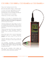
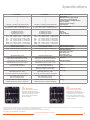
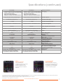
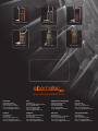
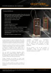
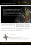
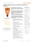
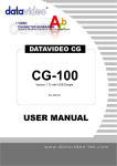
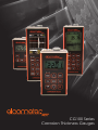
CG100 Series
www.elcometerndt.com
1
Corrosion Thickness Gauges
CG100B, CG100BDL, CG100ABDL & CG100ABDL+
The most advanced in the
Elcometer NDT range, these easy
to use corrosion gauges provide
inspectors with all the features
necessary to accurately measure
the material and coating
thickness at the same time.
Offering a full range of measurement modes
including: Pulse-Echo Temp Comp Mode (PETP) and
Coating Only Mode (CT) to Pulse-Echo Coating Mode
(PECT), the CG100 range allows the inspector to
choose the right tool for the job.
Featuring automatic gain control (AGC) for ease of
use or manual adjustment (-30dB to 70dB) to increase
the amplitude of the received echo to suit the material
properties, the CG100 series are ideal gauges for all
applications.
The time corrected gain (TCG) feature automatically
compensates for sound attenuation through a
material, further increasing the performance of the
gauge.
Built-in Gates allow users to set the measurement
parameters either on or between waveforms,
bypassing any surface echoes or noise from the
material.
Threshold adjustment allows users to adjust the
sensitivity of the gauge to detect signals with lower
amplitudes.
The CG100BDL, CG100ABDL & CG100ABDL+
stores up to 16,000 readings with individual waveforms
in alpha numeric batches with full data logging
via RS232 data output to Elcometer NDT data
management software.
With its high contrasting colour display the
CG100ABDL+ has a refresh rate of 120Hz providing
users with an instant measurement response.
2
www.elcometerndt.com
Thickness Gauges
Advantages
● Range of display & measurement options:
●
●
●
●
●
●
●
●
●
●
●
●
Pulse-Echo, Echo-Echo, Pulse-Echo Temp, Comp Mode (PETP), Coating Only Mode (CT), Pulse-Echo Coating Mode (PECT)
Adjustable gain: -30dB to 70dB range
Automatic gain control (AGC)
Time corrected gain (TCG)
Gate control
Threshold adjustment
64 User defined setups
Multiple language display
Multiple calibration and material selection options
High speed scan mode: 32 readings per second
Differential and minimal thickness alarm modes
Data storage capability: 16,000 readings
and waveforms or B-Scans
Download to Data management software
www.elcometerndt.com
3
CG100B, CG100BDL, CG100ABDL & CG100ABDL+
Model & Part Number
CG100B
CG100BDL
●
●
●
●
●
●
●
●
●
●
PE, PETP (Temp Compensation),
EE (ThruPaint™), EEV, CT (Coating) & PECT
PE, PETP (Temp Compensation),
EE (ThruPaint™), EEV, CT (Coating) & PECT
Display Mode:
Material thickness digits display
B-Scan cross sectional display
Combined B-Scan and digits display
Scan bar display
Coating thickness display
A-Scan display
Measurement Mode¹
Measurement Rate
Manual:
Scan mode
Scan bar display
Measuring Range²
4 readings per second
50 readings per second
6 readings per second
PE:
0.63 - 508mm (0.025 - 19.999 inches)
PETP: 0.63 - 508mm (0.025 - 19.999 inches)
EE:
2.54 - 102mm (0.100 - 4.000 inches)
EEV: 1.27 - 25.4mm (0.050 - 1.000 inches)
CT:
0.01 - 2.54mm (0.001 - 0.100 inches)
PECT: 0.63 - 508mm (0.025 - 19.999 inches)
PECT: 0.01 - 2.54mm (0.001 - 0.100 inches)
±0.01mm (±0.001 inches)
0.01mm (0.001 inches)
1250 - 13,995m/s (0.0492 - 0.5510in/ms)
Measurement Accuracy²
Measurement Resolution
Velocity Calibration Range
Additional Features:³
High speed scan mode
Differential mode
Limit alarm mode
B-Scan display speed
Flaw Mode
Calibration Setups
4 readings per second
50 readings per second
6 readings per second
PE:
0.63 - 508mm (0.025 - 19.999 inches)
PETP: 0.63 - 508mm (0.025 - 19.999 inches)
EE:
2.54 - 102mm (0.100 - 4.000 inches)
EEV: 1.27 - 25.4mm (0.050 - 1.000 inches)
CT:
0.01 - 2.54mm (0.001 - 0.100 inches)
PECT: 0.63 - 508mm (0.025 - 19.999 inches)
PECT: 0.01 - 2.54mm (0.001 - 0.100 inches)
±0.01mm (±0.001 inches)
0.01mm (0.001 inches)
1250 - 13,995m/s (0.0492 - 0.5510in/ms)
●
●
●
●
●
●
15 seconds per screen
15 seconds per screen
6 factory & 64 user-definable setups
transferrable to and from a PC archive
6 factory & 64 user-definable setups
transferrable to and from a PC archive
dual square wave pulsers
up to 140Hz pulse repetition rate
dual square wave pulsers
up to 140Hz pulse repetition rate
time corrected gain (TCG), automatic gain control
(AGC) with 110dB range (limited), or selectable
gain: vlow, low, medium hi or vhi
time corrected gain (TCG), automatic gain control
(AGC) with 110dB range (limited), or selectable
gain: vlow, low, medium hi or vhi
precision 25MHz TCXO with single shot
100MHz 8bit ultra low power 8 bit digitizer
precision 25MHz TCXO with single shot
100MHz 8bit ultra low power 8 bit digitizer
Gates
Damping
Pulser Type
Gain
Timing
4
PE
PETP
Pulse - Echo Mode
The normal display mode,
measures the total thickness from
the base of the transducer probe
to the material density boundary
(typically the back wall). Ideal for
pit and flaw detection.
Pulse - Echo Temp Comp Mode
Similar to the PE mode,
PETP takes into account and
compensates for the variations in
measurement caused by
temperature variations.
www.elcometerndt.com
Specifications
CG100ABDL
CG100ABDL+
●
●
●
●
●
+ Rectified, - Rectified, Full Waveform (RF)
●
●
●
●
●
+ Rectified, - Rectified, Full Waveform (RF)
PE, PETP (Temp Compensation),
EE (ThruPaint™), EEV, CT (Coating) & PECT
PE, PETP (Temp Compensation),
EE (ThruPaint™), EEV, CT (Coating) & PECT
4 readings per second
50 readings per second
6 readings per second
PE:
0.63 - 508mm (0.025 - 19.999 inches)
PETP: 0.63 - 508mm (0.025 - 19.999 inches)
EE:
1.27 - 102mm (0.050 - 4.000 inches)
EEV: 1.27 - 25.4mm (0.050 - 1.000 inches)
CT:
0.01 - 2.54mm (0.001 - 0.100 inches)
PECT: 0.63 - 508mm (0.025 - 19.999 inches)
PECT: 0.01 - 2.54mm (0.001 - 0.100 inches)
±0.01mm (±0.001 inches)
0.01mm (0.001 inches)
1250 - 13,995m/s (0.0492 - 0.5510in/ms)
4 readings per second
32 readings per second
6 readings per second
PE:
0.63 - 508mm (0.025 - 19.999 inches)
PETP: 0.63 - 508mm (0.025 - 19.999 inches)
EE:
1.27 - 102mm (0.050 - 4.000 inches)
EEV: 1.27 - 25.4mm (0.050 - 1.000 inches)
CT:
0.01 - 2.54mm (0.001 - 0.100 inches)
PECT: 0.63 - 508mm (0.025 - 19.999 inches)
PECT: 0.01 - 2.54mm (0.001 - 0.100 inches)
±0.01mm (±0.001 inches)
0.01mm (0.001 inches)
1250 - 9,999m/s (0.0492 - 0.3936in/ms)
Model & Part Number
Display Mode:
Material thickness digits display
B-Scan cross sectional display
Combined B-Scan and digits display
Scan bar display
Coating thickness display
A-Scan display
Measurement Mode¹
Measurement Rate
Manual:
Scan mode
Scan bar display
Measuring Range²
Measurement Accuracy²
Measurement Resolution
Velocity Calibration Range
Additional Features:³
High speed scan mode
Differential mode
Limit alarm mode
●
●
●
●
●
●
adjustable display speed
Basic prove-up flaw detection using
single element angle beam transducers
adjustable display speed
Basic prove-up flaw detection using
single element angle beam transducers
B-Scan display speed
Flaw Mode
6 factory & 64 user-definable setups
transferrable to and from a PC archive
6 factory & 64 user-definable setups
transferrable to and from a PC archive
Calibration Setups
3 fully adjustable gates:
start, stop, width & threshold
3 fully adjustable gates:
start, stop, width & threshold
adjustable; impedance matching for
optimising transducer performance
dual 200 volt square wave pulsers with adjustable
pulse width (spike, thin, wide)
and 50 volt cut/boost for greater penetration
Gates
Damping
dual 200 volt square wave pulsers with adjustable Pulser Type
pulse width (spike, thin, wide)
and 50 volt cut/boost for greater penetration
manual, automatic gain control (AGC)
with 110dB range (limited),
time corrected gain (TCG)
manual, automatic gain control (AGC)
with 110dB range (limited),
time corrected gain (TCG)
precision 25MHz TCXO with single shot
100MHz 8bit ultra low power 8 bit digitizer
precision 25MHz TCXO with single shot
100MHz 8bit ultra low power 8 bit digitizer
Gain
Timing
EE
EEV
Echo - Echo Mode
Also known as the ThruPaint™
Mode, EE ignores the coating
thickness, displaying the material
thickness from the top surface
of the material to the material
density boundary.
Echo - Echo Verify Mode
The echo-echo verify mode
measures by comparing the
values between 3 reflections and
is commonly used to eliminate
errors from surface coatings and
to make measurements in multiple
layered materials.
¹ PE: Pulse-Echo Mode, PETP: Pulse-Echo Temperature Compensation Mode, EE: Echo-Echo (ThruPaint™) Mode, EEV: Echo-Echo Verify, CT: Coating Thickness Mode,
PECT: Pulse-Echo, Coating Thickness Mode; See page 3 for further information
² Measuring range & accuracy depends on material, surface conditions and the transducer selected
³ See page 5 for a full explanation of the features
www.elcometerndt.com
5
CG100B, CG100BDL, CG100ABDL & CG100ABDL+
Model & Part Number
CG100B
CG100BDL
•
•
•
•
•
Data logging
Calibration Options
16,000 with B-scan image & gauge settings
210,000 - coating, material, min, max thickness
sequential and grid logging
Alpha numeric batch identification
OBSTRUCT indicates inaccessible locations
single, two point, velocity & material type
single, two point, velocity & material type
dual element
dual element
1 - 10MHz
1 - 10MHz
automatic & manual - selectable from a list
automatic & manual - selectable from a list
automatic
automatic
Probe Zero
automatic & manual (via integrated probe disk)
automatic & manual (via integrated probe disk)
Display
1/8 VGA (grayscale)
62 x 45.7mm (2.4 x 1.8 inches) viewable area
1/8 VGA (grayscale)
62 x 45.7mm (2.4 x 1.8 inches) viewable area
Display Refresh Rate
Units (selectable)
Backlight
Repeatability / Stability Indicator
Battery Type
Battery Life (approximate)
Low Battery Indicator
Battery Save Mode
Operating Temperature
Size (w x h x d)
Weight (including batteries)
Aluminium case design with gasket sealed end
caps, waterproof membrane keypad
25Hz
mm or inches
on / off / auto
●
3 x AA alkaline
150 hours
●
auto
-10 to 60ºC (14 to 140ºF)
63.5 x 165.0 x 31.5mm (2.5 x 6.5 x 1.24 inches)
383g (13.5oz)
25Hz
mm or inches
on / off / auto
●
3 x AA alkaline
150 hours
●
auto
-10 to 60ºC (14 to 140ºF)
63.5 x 165.0 x 31.5mm (2.5 x 6.5 x 1.24 inches)
383g (13.5oz)
●
●
Transducer Connector Type
RS232 Interface
Packing List
LEMO
Bi-directional
Elcometer NDT CG100B gauge, couplant, carry
case, user manual, test certificate,
3 x AA batteries
Transducer Probe Type
Transducer Frequency Range
Transducer Recognition
V-path / dual path error correction
PECT
CT
Coating Only Mode
Displays the thickness of the
coating applied to the material.
6
LEMO
Bi-directional
Elcometer NDT CG100BDL gauge, couplant,
carry case, user manual, test certificate,
3 x AA batteries, software, transfer cable
www.elcometerndt.com
Pulse - Echo Coating Mode
Displays both the material
thickness (PE) and the coating
thickness (CT) at the same time.
Specifications (continued)
CG100ABDL
•
•
•
•
•
CG100ABDL+
16,000 with A/B-scan image & gauge settings
210,000 - coating, material, min, max thickness
sequential and grid logging
Alpha numeric batch identification
OBSTRUCT indicates inaccessible locations
•
•
•
•
•
single, two point, velocity & material type
single, two point, velocity & material type
dual element & flaw prove up
dual element & flaw prove up
1 - 10MHz
1 - 10MHz
automatic & manual - selectable from a list
automatic & manual - selectable from a list
automatic
automatic
automatic & manual (via integrated probe disk)
automatic & manual (via integrated probe disk)
1/8 VGA (grayscale)
62 x 45.7mm (2.4 x 1.8 inches) viewable area
Calibration Options
Transducer Probe Type
Transducer Frequency Range
Transducer Recognition
V-path / dual path error correction
Probe Zero
1/4 VGA AMOLED colour display
Display
57.6 x 43.2mm (2.27 x 1.78 inches) viewable area
25Hz
mm or inches
on / off / auto
●
3 x AA alkaline
50 hours
●
auto
-10 to 60ºC (14 to 140ºF)
63.5 x 165.0 x 31.5mm (2.5 x 6.5 x 1.24 inches)
383g (13.5oz)
120Hz
mm or inches
adjustable brightness
●
3 x AA alkaline
25 hours
●
auto
-10 to 60ºC (14 to 140ºF)
63.5 x 165.0 x 31.5mm (2.5 x 6.5 x 1.24 inches)
383g (13.5oz)
●
●
LEMO
Bi-directional
Elcometer NDT CG100ABDL gauge, couplant,
carry case, user manual, test certificate,
3 x AA batteries, software, transfer cable
Model & Part Number
8,000 with A/B-scan image & gauge settings Data logging
210,000 - coating, material, min, max thickness
sequential and grid logging
Alpha numeric batch identification
OBSTRUCT indicates inaccessible locations
LEMO
Bi-directional
Elcometer NDT CG100ABDL+ gauge, couplant,
carry case, user manual, test certificate,
3 x AA batteries, software, transfer cable
Display Refresh Rate
Units (selectable)
Backlight
Repeatability / Stability Indicator
Battery Type
Battery Life (approximate)
Low Battery Indicator
Battery Save Mode
Operating Temperature
Size (w x h x d)
Weight (including batteries)
Aluminium case design with gasket sealed end
caps, waterproof membrane keypad
Transducer Connector Type
RS232 Interface
Packing List
TCG
FLAW MODE
Time Corrected Gain
Time corrected gain
increases gain as time increases,
in order to achieve an over
all level of sensitivity for the
same flaw/reflector at different
distances.
Basic Flaw Mode
Basic prove-up flaw detection
using single element angle beam
transducers is available on the
CG100ABDL and CG100ABDL+
corrosion thickness gauges.
¹ PE: Pulse-Echo Mode, PETP: Pulse-Echo Temperature Compensation Mode, EE: Echo-Echo (ThruPaint™) Mode, EEV: Echo-Echo Verify, CT: Coating Thickness Mode,
PECT: Pulse-Echo, Coating Thickness Mode; See page 3 for further information
² Measuring range & accuracy depends on material, surface conditions and the transducer selected
³ See page 5 for a full explanation of the features
www.elcometerndt.com
7
Corrosion Gauges
Velocity Gauges
Precision Gauges
Flaw Detection
Sonic Gauges
Bolt Gauges
www.elcometerndt.com
ENGLAND
Elcometer Limited
Manchester M43 6BU
Tel: +44 (0)161 371 6000
Fax: +44 (0)161 371 6010
e-mail: [email protected]
USA
Elcometer Inc
Rochester Hills Michigan 48309
Tel: +1 248 650 0500
Toll Free: 800 521 0635
Fax: +1 248 650 0501
e-mail: [email protected]
REPUBLIC OF SINGAPORE
Elcometer (Asia) Pte Ltd
Singapore 589472,
Tel: +65 6462 2822
Fax: +65 6462 2860
e-mail: [email protected]
JAPAN
Elcometer KK
Minato-ku, Tokyo
Tel: +81 (0)3-4530-9714
Fax: +81 (0)3-4530-9713
e-mail: [email protected]
FRANCE
Elcometer Sarl
45430 BOU
Tel: +33 (0)2 38 86 33 44
Fax: +33 (0)2 38 91 37 66
e-mail: [email protected]
GERMANY
Elcometer Instruments GmbH
D-73431 Aalen
Tel: +49(0)7361 52806 0
Fax: +49(0)7361 52806 77
e-mail: [email protected]
BELGIUM
Elcometer SA
B-4681 Hermalle /s Argenteau
Tel: +32 (0)4 379 96 10
Fax: +32 (0)4 374 06 03
e-mail: [email protected]
THE NETHERLANDS
Elcometer NL
3584 BH Utrecht
Tel: +31 (0)30 210.7005
Fax: +31 (0)30 210.6666
email: [email protected]
8
www.elcometerndt.com
© Elcometer Limited, 2011. SLI0054 Issue 1
All rights reserved. No part of this document may be reproduced, transmitted, stored (in a retrieval system or otherwise), or translated into any language, in any form, or by any means, without the prior written
permission of Elcometer Limited.
Elcometer is a registered trademark of Elcometer Limited. ThruPaint™ is a trademark of Elcometer Limited. All other trademarks are acknowledged. Due to our policy of continuous improvement,
Elcometer Limited reserves the right to change specifications without notice.