1
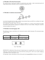
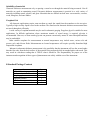
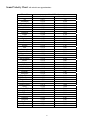
Model No. UTG-2650 Phase II USA 21 Industrial Ave Upper Saddle River, NJ. 07458 USA P: (201) 962‐7373 F: (201) 962‐8353 E‐mail: [email protected] www.phase2plus.com Contents 1.Introduction 2.Technical Specifications 3.Names and Functions of Various Parts for UTG‐2650 4. Operation 4.1 Calibration 4.2 Measuring 4.3 Saving Test Results 4.4 Reading Saved Results 4.5 System Setting‐Change Resolution and/or Units 4.6 Minimum Capture 4.7 Two Point Calibration 5. Methods of Thickness Measurements 5.1 Measuring planar surface 5.1.1 General methods 5.1.2 Method of precision measurement 5.1.3 Method of continuous measurements 5.2 Methods for measuring pipe walls 6. Maintenance 7.Special Applications & Couplant Gels 8. Standard Package Contents 2 1. Introduction The UTG‐2650 is a simple to use, highly accurate, hand‐held Ultrasonic Thickness Gauge with the ability to measure ultra‐thin materials in super high resolution. Utilizing it’s state of the art microprocessor and ultrasonic technology the 2650 offers you many outstanding features such as quick scan and extended memory. It features reliable and stable readings, standard or dual element measuring modes, convenient data display (in both millimeters and inches),high resolution .0001” (0.001mm), ease of operation, low power consumption(two AA batteries). These features make UTG‐2650 unequalled in its performance as well as its value! 2. Technical Specifications ● Measuring range: (Steel) IE Standard Mode: 0.059” – 7.87” (1.5‐18mm) EE High Precision Mode: 0.012” – 0.394” (0.30mm – 10.0mm) ● Accuracy: +/‐ 0.0002” (if thickness is below 3mm) +/‐ 0.002” (if thickness is below 20mm) ● Display Resolution:. Selectable 0.01”, 0.001”, 0.0001” (0.1, 0.01, 0.001mm) ● Memory capacity:500 test values ● Measuring frequency:4MHz(Normal mode) up to 25MHz. ● Sound velocity range:0.0394 – 0.3936in/min (1,000‐9,999m/s) ● Display LCD: 42x57mm with Backlight and adjustable contrast. Font size up to .054” ● Operating Temp: ‐10º ‐ +50ºC ● Battery: Two 1.5V AA batteries ● Dimensions:5.86” x 2.87” x 1.25”(149mm×73mm×32mm) ● The relative humidity:<90% ● Weight: 5.6oz (200g)(unit only) 3 3. Names and Functions for UTG-2650 ● Power on/Reset key ON/RST –to turn on or reset the tester. When the tester is turned on, LCD will display the value of sound velocity used for the last measurement. The gauge will shut off automatically if idle for 4 minutes. ● Menu key MENU- to setup the tester .Press this key to move highlighted item to the following menus-Save(N=1,2,3,4 or 5),Menu, EE, OFF. ● Enter key to accept the job selected by . If Off is highlighted by pressing MENU the gauge .Pressing MENU twice will send the gage back to main operation. , hit to switch off ● Calibration key CAL – to calibrate the tester with built-in block on the unit. ● Operating key and ● Sound Velocity key VEL –to set the value of sound velocity to be used .Press the digit to be changed and use operating key and to get the value. to move on LCD toward 5900 Up to five sound velocity values can be pre-stored by pressing VEL key when the value is set. Press VEL key in sequence during the measurement will load the values saved in the tester . 4 4.Operation 4.1Calibration Set the sound velocity to be 0.232”(5900m/s) .Put a pea sized drop of couplant gel on calibration block built-in on the gauge. Press the probe on the face of the block to obtain measurement .LCD screen will display a value. Lift the probe off the block. Then press the up and down arrows to adjust the value on the display to match 0.157”(4.00mm). You may need to press the Back Arrow button to move the cursor from column to column. Once the value of 0.157” has been obtained, press the CAL button to save the calibration. Now place the probe back on the block to verify the reading. If value doesn’t not show 0.157” or 4.00mm, repeat above steps to get correct reading. Verification should be carried out every time the unit is turned on. This should be done on either the built-in test block or a swatch of your own material with a known thickness value. 4.2 Measuring Put a small drop of couplant gel on the work-piece, then place the probe on the surface of your sample. The thickness value will display on LCD screen in either mm or inch. The gauge shows the measuring result whenever the probe is coupled with the work-piece for longer than 2 seconds with couplant gel. 4.3 Saving Test Results Test results can be saved into 5 individual files. Each file holds up to 100 values. To save test results, highlight SaveN by pressing MENU press to change N to required number. Press MENU when the file number N is set. The gauge is now ready to save measuring data to the file numbered above. During measurement, press MEM to save the reading to SaveN file. A flash mark of “Memory” will seen on LCD if the value is successfully saved. 4.4 Reading Saved Results To read saved results from the tester ,highlight SaveN by pressing MENU, press to change N to required number ,Press MEM to open the file ,”NO” points to current result ,”Total” is the number of the readings in “SaveN” file .Press will delete the current result from the file .Use and keys to display the other results in this file. 4.5 System Setting-Change Resolution and/or Units Press MENU until MENU is highlighted ,press to enter system setting. Use operating key select the function and press to adjust the setting accordingly. and/or to To change display resolution for the tester, enter “System Setup” and choose ‘HIGH” or 0.0001” or “MID” 0.001” (0.01mm) or LOW 0.01” for the display resolution. This setting can be seen on LCD with “HIGH” or “MID” or “LOW”. Switch between “Metric” and “Imperial” units can be done through Menu→System Setup→Units→Press Press MENU key or perform measurement to return to the main operation, after system setting. 5 4.6 Minimum Capture (Scan Feature) If this function is set to “ON” from system setting, it is ready to capture minimum reading in the measurement. LCD will show the current thickness while the probe is coupled with the sample .as soon as you release the probe from your part, the LCD displays the minimum reading and “MIN” will flash six times. Measuring during the flashing will send the results into the capture array to get the minimum reading. 4.7 Two Point Calibration Use two calibration samples with their known thicknesses, which are better or close to the upper and lower limits of measuring range respectively. Turn on 2-point calibration function from system setting (section 4.6) and turn off “Min Capture”. press CAL While checking the thickness of the thinner sample, ”Thin” will be seen on the LCD along with the thickness result. Use and keys to change the reading to the thickness of thinner sample .Press CA L to finish the first point calibration. Press CAL and to repeat the above steps for the second(thicker)sample. 5 Methods of Thickness Measurement 5.1.Measuring planar surface 5.1.1.General methods a) Single measurement method This method involves measuring the thickness at a single point. b) Double measurement method This method involves performing two thickness measurements near a single spot using a dual sensor probe rotated from 0°to 90° respectively, with respect to the split face (Fig.1).Take the smaller of the two indicated values as the thickness of the material. Fig 1 c) Multiple point measurements within a circle of φ=1.18” (30mm). This method involves performing a number of measurements within a circle having a maximum diameter of about 1.18” (30mm)(fig.2). Take the minimum indicated value as the thickness of the material. Fig.2 6 5.1.2Method of Precision Measurement This method involves increasing the number of measurement spots around a certain measurement point and expressing the thickness fluctuation in terms of isothickness contour lines, fig.3. Fig. 3 Fig 3. 5.1.3Method of continuous measurements Fig.4 As in fig.4, this method involves taking continuous measurements along a specified line according to the single measurement method, at intervals of 5mm or less. Your application will dictate which is the most effective method to use. If unsure of best method, the double measurement method should be employed in combination with one of other methods. Taking into account the corrosion condition of the material 5.2 Methods for measuring pipe walls The thickness of a pipe or round object can be measured accurately with this instrument. The measurement range is shown in Table 5.1. Table5.1 Probe type Pipe diameter inch Thickness Inch (mm) (mm) Pt-08,10 and 12 ≥φ1.0” (25mm) ≥ 0.04”(1.2mm) Fig.5 5 Pipe sample IMPORTANT! the Split-plane of the probe may be along the pipe axis or perpendicular to it as shown in Fig.5.For small pipes, measurement should be made in both directions (moving probe a little bit ),the smaller displaying value should be taken as the thickness value. For large pipes, measure the thickness of the wall along the direction perpendicular to the pipe axis, fig.6and 7. 7 Fig.6 Pipe sample Fig.7 Bottom view of probe 6.Maintenance Be sure to clean the probe and cable after each use. Grease, oil and dust will cause the cable of the probe to dry out and shorten life expectancy. If the unit is not to be used for a long period of time, remove the batteries to avoid battery leakage and corrosion of the battery contacts. Avoid storing the unit in a damp or extremely hot environment. ● DO NOT OPEN INSTRUMENT! This will automatically void your warranty. 7) Special Applications & Couplant Gel notes: Measuring hot surfaces The velocity of sound through a substance is dependant upon its temperature. As materials heat up, the velocity of sound through them decreases. In most applications with surface temperatures less than about 100°, no special procedures must be observed. At temperatures above this point, the change in sound velocity of the material being measured starts to have a noticeable effect upon ultrasonic measurement. At such elevated temperatures, it is recommended that the user perform a calibration procedure on a sample piece of known thickness, which is at or near the temperature of the material to be measured. This will allow the gauge to correctly calculate the velocity of sound through the hot material. When performing measurements on hot surfaces, it may also be necessary to use a specially constructed high-temperature transducer. These transducers are built using materials which can withstand high temperatures. Even so, it is recommended that the probe be left in contact with the surface for as short a time as needed to acquire a stable measurement. While the transducer is in contact with a hot surface, it will begin to heat up, and through thermal expansion and other effects, may begin to adversely affect the accuracy of measurements. Measuring laminated materials. Laminated materials are unique in that their density (and therefore sound-velocity) may vary considerably from one piece to another. Some laminated materials may even exhibit noticeable changes in sound-velocity across a single surface. The only way to reliably measure such materials is by performing a calibration procedure on a sample piece of known thickness. Ideally, this sample material should be a part of the same piece being measured, or at least from the same lamination batch. By calibrating to each test piece individually, the effects of variation of sound-velocity will be minimized. An additional important consideration when measuring laminates, is that any included air gaps or pockets will cause an early reflection of the ultrasound beam. This effect will be noticed as a sudden decrease in thickness in an otherwise regular surface. While this may impede accurate measurement of total material thickness, it does provide the user with positive indication of air gaps in the laminate. 8 Suitability of materials Ultrasonic thickness measurements rely on passing a sound wave through the material being measured. Not all materials are good at transmitting sound. Ultrasonic thickness measurement is practical in a wide variety of materials including metals, plastics, and glass. Materials that are difficult include some cast materials, concrete, wood, fiberglass, and some rubber. Couplant Gels All ultrasonic applications require some medium to couple the sound from the transducer to the test piece. Typically a high viscosity liquid is used as the medium. The sound used in ultrasonic thickness measurement does not travel through air efficiently. A wide variety of couplant materials may be used in ultrasonic gauging. Propylene glycol is suitable for most applications. In difficult applications where maximum transfer of sound energy is required, glycerin is recommended. However, on some metals glycerin can promote corrosion by means of water absorption and thus may be undesirable. Other suitable couplants for measurements at normal temperatures may include water, various oils and greases, gels, and silicone fluids. Measurements at elevated temperatures will require specially formulated high temperature couplants. Inherent in ultrasonic thickness measurement is the possibility that the instrument will use the second rather than the first echo from the back surface of the material being measured while in standard pulse-echo mode. This may result in a thickness reading that is TWICE what it should be. The Responsibility for proper use of the instrument and recognition of these types of phenomenon rests solely with the user of the instrument. 8.Standard Package Contents Items UTG-2650(main gauge unit) Probe Coupling gel Operation Manual Alkaline Battery(size AA) Carry case Qty 1 1 1 1 2 1 9 Sound Velocity Chart: All velocities are approximations: Material Air Aluminum Alumina Oxide Beryllium Boron Carbide Brass Cadmium Copper Glass(crown) Glycerin Gold Ice Inconel Iron Iron (cast) Lead Magnesium Mercury Molybdenum Monel Neoprene Nickel Nylon, 6.6 Oil (SAE 30) Platinum Plexiglass Polyethylene Polystyrene Polyurethane Quartz Rubber, Butyl Silver Steel, Mild Steel, Stainless Teflon Tin Titanium Tungsten Uranium Water Zinc Sound Velocity Inch/µS 0.013 0.250 0.390 0.510 0.430 0.170 0.110 0.180 0.210 0.075 0.130 0.160 0.220 0.230 0.180 0.085 0.230 0.057 0.250 0.210 0.063 0.220 0.100 0.067 0.130 0.110 0.070 0.0930 0.0700 0.230 0.070 0.140 0.233 0.230 0.060 0.130 0.240 0.200 0.130 0.584 0.170 M/s 330 6300 9900 12900 11000 4300 2800 4700 5300 1900 3200 4000 5700 5900 4600 2200 5800 1400 6300 5400 1600 5600 2600 1700 3300 1700 1900 2400 1900 5800 1800 3600 5900 5800 1400 3300 6100 5200 3400 1480 4200 10 Main Headquarters: U.S.A Phase II Machine & Tool, Inc. 21 Industrial Ave Upper Saddle River, NJ. 07458 USA Tel: (201) 962‐7373 Fax: (201) 962‐8353 General E‐Mail: [email protected] BEIJING, CHINA Phase II Measuring Instruments (Beijing) Ltd. Room 301, Bldg 2 Qing Yuan Xi Li, Haidian District, Beijing 100192,China Tel:+86‐10‐59792409 Fax:+86‐10‐59814851 General E‐mail: [email protected] MEXICO Phase II de Mexico Calle A No. 4 Promer Piso Col. San Marcos Azcapotzalco C.P 02020 Mexico Tel: 011‐525‐5538‐39771 Fax: same General E‐mail: [email protected] VENEZUELA Phase II Herramientas Universales EDCM. CA. Av. Francisco Lazo Marti CC Plaza Santa Monica PB Local Santa Monica, Caracas 1040 Venezuela Tel: 212‐690‐28‐21 Fax: 212‐693‐29‐16 E‐mail: [email protected] 11