1
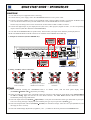
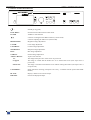
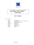
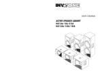
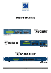
User’s Manual
MODELS: OHD888 & OHD888-AG
ANALOG WAY®
OPTIMIZER HD – AW 5073
EDITION : 03 / 08
OPTIMIZER HD
ENGLISH
SAFETY INSTRUCTIONS
All of the safety and operating instructions should be read before the product is operated and should be retained for further
reference. Please follow all of the warnings on this product and its operating instructions.
CAUTION:
WARNING:
To prevent the risk of electric shock and fire, do not expose this device to rain, humidity or intense
heat sources (such as heaters or direct sunlight). Slots and openings in the device are provided for
ventilation and to avoid overheating. Make sure the device is never placed on or near a textile
surface that could block the openings. Also keep away from excessive dust, vibrations and shocks.
POWER:
Only use the power supply indicated on the device or on the power source. Devices equipped with a
grounding plug should only be used with a grounding type outlet. In no way should this grounding
be modified, avoided or suppressed.
POWER CORD: Use the On (I) / Off (O) switch to power On or Off devices equipped with that switch. All other
devices should be plugged and unplugged from wall outlet. In both cases, please follow these
instructions:
- The power cord of the device should be unplugged from the outlet when left unused for several
days.
- To unplug the device, do not pull on the power cord but always on the plug itself.
- The outlet should always be near the device and easily accessible.
- Power supply cords should be routed so that they are not likely to be walked on or pinched by
items placed upon or against them.
If the power supply cord is damaged, unplug the device. Using the device with a damaged power
supply cord may expose you to electric shocks or other hazards. Verify the condition of the power
supply cords once in a while. Contact your dealer or service center for replacement if damaged.
CONNECTIONS: All inputs and outputs (except for the power input) are TBTS defined under EN60950.
SERVICING:
Do not attempt to service this product yourself by opening or removing covers and screws since it
may expose you to electric shocks or other hazards. Refer all problems to qualified service
personnel.
OPENINGS:
Never push objects of any kind into this product through the openings. If liquids have been spilled or
objects have fallen into the device, unplug it immediately and have it checked by a qualified
technician.
PAGE 2
OPTIMIZER HD
INSTRUCTIONS DE SÉCURITÉ
Afin de mieux comprendre le fonctionnement de cet appareil nous vous conseillons de bien lire toutes les consignes de sécurité et de fonctionnement de
l’appareil avant utilisation. Conserver les instructions de sécurité et de fonctionnement afin de pouvoir les consulter ultérieurement. Respecter toutes les
consignes marquées dans la documentation, sur le produit et sur ce document.
INSTALLATION : Veillez à assurer une circulation d’air suffisante pour éviter toute surchauffe à l’intérieur de l’appareil. Ne placez pas l’appareil sur ou
proximité de surface textile susceptible d’obstruer les orifices de ventilation. N’installez pas l’appareil à proximité de sources de chaleur comme un radiateur
ou une bouche d’air chaud, ni dans un endroit exposé au rayonnement solaire direct, à des poussières excessives, à des vibrations ou à des chocs mécaniques.
Ceci pourrait provoquer un mauvais fonctionnement et un accident.
ALIMENTATION : Ne faire fonctionner l’appareil qu’avec la source d’alimentation indiquée sur l’appareil ou sur son bloc alimentation. Pour les appareils
équipés d’une alimentation principale avec fil de terre, ils doivent être obligatoirement connectés sur une source équipée d’une mise à la terre efficace. En
aucun cas cette liaison de terre ne devra être modifiée, contournée ou supprimée.
FRANÇAIS
ATTENTION : Afin de prévenir tout risque de choc électrique et d’incendie, ne pas exposer cet appareil à la pluie, à l’humidité et aux sources de chaleur
intense.
CORDON D’ALIMENTATION : Pour les appareils équipés d’un interrupteur général (Marche I / Arrêt O), la mise sous tension et la mise hors tension se fait
en actionnant cet interrupteur général. Pour les appareils sans interrupteur général, la mise sous tension et la mise hors tension se fait directement en
connectant et déconnectant le cordon d'alimentation de la prise murale.
Dans les 2 cas ci-dessus appliquer les consignes suivantes :
- Débrancher le cordon d'alimentation de la prise murale si vous prévoyez de ne pas utiliser l'appareil pendant quelques jours ou plus.
- Pour débrancher le cordon, tirez le par la fiche. Ne tirez jamais sur le cordon proprement dit.
- La prise d’alimentation doit se trouver à proximité de l’appareil et être aisément accessible.
- Ne laissez pas tomber le cordon d’alimentation et ne posez pas d’objets lourds dessus.
Si le cordon d’alimentation est endommagé, débranchez le immédiatement de la prise murale. Il est dangereux de faire fonctionner cet appareil avec un cordon
endommagé, un câble abîmé peut provoquer un risque d’incendie ou un choc électrique. Vérifier le câble d’alimentation de temps en temps. Contacter votre
revendeur ou le service après vente pour un remplacement.
CONNEXIONS : Toutes les entrées et sorties (exceptée l’entrée secteur) sont de type TBTS (Très Basse Tension de Sécurité) définies selon EN 60950.
RÉPARATION ET MAINTENANCE : L’utilisateur ne doit en aucun cas essayer de procéder aux opérations de dépannage, car l’ouverture des appareils par
retrait des capots ou de toutes autres pièces constituant les boîtiers ainsi que le dévissage des vis apparentes à l’extérieur, risque d’exposer l’utilisateur à des
chocs électriques ou autres dangers. Contacter le service après vente ou votre revendeur ou s’adresser à un personnel qualifié uniquement.
OUVERTURES ET ORIFICES : Les appareils peuvent comporter des ouvertures (aération, fentes, etc...), veuillez ne jamais y introduire d’objets et ne jamais
obstruer ses ouvertures. Si un liquide ou un objet pénètre à l’intérieur de l’appareil, débranchez immédiatement l’appareil et faites le contrôler par un personnel
qualifié avant de le remettre en service.
Allo scopo di capire meglio il funzionamento di questa apparecchiatura vi consigliamo di leggere bene tutti i consigli di sicurezza e di funzionamento prima
dell’utilizzo. Conservare le istruzioni di sicurezza e di funzionamento al fine di poterle consultare ulteriormente. Seguire tutti i consigli indicati su questo
manuale e sull’apparecchiatura.
ATTENZIONE : Al fine di prevenire qualsiasi rischio di shock elettrico e d’incendio, non esporre l’apparecchiatura a pioggia, umidità e a sorgenti di
eccessivo calore.
INSTALLAZIONE : Assicuratevi che vi sia una sufficiente circolazione d’aria per evitare qualsiasi surriscaldamento all’interno dell’apparecchiatura. Non
collocare l’apparecchiatura in prossimità o su superfici tessili suscettibili di ostruire il funzionamento della ventilazione. Non installate l’apparecchiatura in
prossimità di sorgenti di calore come un radiatore o una fuoruscita d’aria calda, né in un posto esposto direttamente ai raggi del sole, a polvere eccessiva, a
vibrazioni o a shock meccanici. Ció potrebbe provocare un erroneo funzionamento e un incidente.
ALIMENTAZIONE : Far funzionare l’apparecchiatura solo con la sorgente d’alimentazione indicata sull’apparecchiatura o sul suo alimentatore. Per le
apparecchiature fornite di un’alimentazione principale con cavo di terra, queste devono essere obbligatoriamente collegate su una sorgente fornita di una
efficiente messa a terra. In nessun caso questo collegamento potrà essere modificato, sostituito o eliminato.
CAVO DI ALIMENTAZIONE : Per le apparecchiature fornite di interruttore generale (Acceso I / Spento O), l’accensione e lo spegnimento
dell’apparecchiatura si effettuano attraverso l’interruttore. Per le apparecchiature senza interruttore generale, l’accensione e lo spegnimento si effettuano
direttamente inserendo o disinserendo la spina del cavo nella presa murale.
In entrambe i casi applicare i seguenti consigli :
- Disconnettere l’apparecchiatura dalla presa murale se si prevede di non utilizzarla per qualche giorno.
- Per disconnettere il cavo tirare facendo forza sul connettore.
- La presa d’alimentazione deve trovarsi in prossimità dell’apparecchiatura ed essere facilmente accessibile.
- Non far cadere il cavo di alimentazione né appoggiarci sopra degli oggetti pesanti.
Se il cavo di alimentazione é danneggiato, spegnere immediatamente l’apparecchiatura. E’ pericoloso far funzionare questa apparecchiatura con un cavo di
alimentazione danneggiato, un cavo graffiato puó provocare un rischio di incendio o uno shock elettrico. Verificare il cavo di alimentazione spesso. Contattare
il vostro rivenditore o il servizio assistenza per una sostituzione.
CONNESSIONE : Tutti gli ingressi e le uscite (eccetto l’alimentazione) sono di tipo TBTS definite secondo EN 60950.
RIPARAZIONI E ASSISTENZA : L’utilizzatore non deve in nessun caso cercare di riparare l’apparecchiatura, poiché con l’apertura del coperchio metallico o
di qualsiasi altro pezzo costituente la scatola metallica, nonché svitare le viti che appaiono esteriormente, poiché ció puó provocare all’utilizzatore un rischio
di shock elettrico o altri rischi.
APERTURE DI VENTILAZIONE : Le apparecchiature possono comportare delle aperture di ventilazione, si prega di non introdurre mai oggetti o ostruire le
sue fessure. Se un liquido o un oggetto penetra all’interno dell’apparecchiatura, disconnetterla e farla controllare da personale qualificato prima di rimetterla in
servizio.
PAGE 3
ITALIANO
ISTRUZIONI DI SICUREZZA
OPTIMIZER HD
SICHERHEITSHINWEISE
Um den Betrieb dieses Geräts zu verstehen, raten wir Ihnen vor der Inbetriebnahme alle Sicherheits- und Betriebsanweisungen genau zu lesen. Diese
Sicherheits- und Betriebsanweisungen für einen späteren Gebrauch sicher aufbewahren. Alle in den Unterlagen, an dem Gerät und hier angegebenen
Sicherheitsanweisungen einhalten.
VORSICHT & WARNUNG
ACHTUNG: um jegliches Risiko eines Stromschlags oder Feuers zu vermeiden, das Gerät nicht Regen, Feuchtigkeit oder intensiven Wärmequellen aussetzen.
EINBAU: Eine ausreichende Luftzufuhr sicherstellen, um jegliche Überhitzung im Gerät zu vermeiden. Das Gerät nicht auf und in Nähe von
Textiloberflächen, die Belüftungsöffnungen verschließen können, aufstellen. Das Gerät nicht in Nähe von Wärmequellen, wie z.B. Heizkörper oder
Warmluftkappe, aufstellen und es nicht dem direkten Sonnenlicht, übermäßigem Staub, Vibrationen oder mechanischen Stößen aussetzen. Dies kann zu
Betriebsstörungen und Unfällen führen.
DEUTSCH
STROMVERSORGUNG: Das Gerät nur mit der auf dem Gerät oder dem Netzteil angegebenen Netzspannung betreiben. Geräte mit geerdeter
Hauptstromversorgung müssen an eine Stromquelle mit effizienter Erdung angeschlossen werden. Diese Erdung darf auf keinen Fall geändert, umgangen oder
entfernt werden.
STROMKABEL: Für Geräte mit einem Hauptschalter (Ein/Aus) erfolgt die Stromversorgung und Unterbrechung mittels dieses Hauptschalters. Geräte ohne
Hauptschalter werden durch das Einstecken oder Herausziehen des Steckers in den Wandanschluß ein- oder ausgeschaltet. Für beide Fälle gelten folgende
Richtlinien:
- Den Stecker aus dem Wandanschluß herausziehen wenn Sie das Gerät mehrere Tage oder länger nicht benutzen.
- Das Kabel mittels dem Stecker herausziehen. Niemals am Stromkabel selbst ziehen.
- Die Steckdose muß sich in der Nähe des Geräts befinden und leicht zugänglich sein.
- Das Stromkabel nicht fallen lassen und keine schweren Gegenstände auf es stellen.
Wenn das Stromkabel beschädigt ist, das Gerät sofort abschalten. Es ist gefährlich das Gerät mit einem beschädigten Stromkabel zu betreiben; ein abgenutztes
Kabel kann zu einem Feuer oder Stromschlag führen. Das Stromkabel regelmäßig untersuchen. Für den Ersatz, wenden Sie sich an Ihren Verkäufer oder
Kundendienststelle.
ANSCHLÜSSE: Bei allen Ein- und Ausgängen (außer der Stromversorgung) handelt es sich, gemäß EN 60950, um Sicherheits- Kleinspannunganschlüsse.
REPARATUR UND WARTUNG : Der Benutzer darf keinesfalls versuchen das Gerät selbst zu reparieren, die Öffnung des Geräts durch Abnahme der
Abdeckhaube oder jeglichen anderen Teils des Gehäuses sowie die Entfernung von außen sichtbaren Schrauben zu Stromschlägen oder anderen Gefahren für
den Benutzer führen kann. Wenden Sie sich an Ihren Verkäufer, Ihre Kundendienststelle oder an qualifizierte Fachkräfte.
ÖFFNUNGEN UND MUNDUNGEN: Die Geräte können über Öffnungen verfügen (Belüftung, Schlitze, usw.). Niemals Gegenstände in die Öffnungen
einführen oder die Öffnungen verschließen. Wenn eine Flüssigkeit oder ein Gegenstand in das Gerät gelangt, den Stecker herausziehen und es vor einer neuen
Inbetriebnahme von qualifiziertem Fachpersonal überprüfen lassen.
INSTRUCCIONES DE SEGURIDAD
Para comprender mejor el funcionamiento de este aparato, le recomendamos que lea cuidadosamente todas las consignas de seguridad y de funcionamiento del
aparato antes de usarlo. Conserve las instrucciones de seguridad y de funcionamiento para que pueda consultarlas posteriormente. Respete todas las consignas
indicadas en la documentación, relacionadas con el producto y este documento.
PRECAUCIONES Y OBSERVACIONES
ESPAÑOL
CUIDADO : Para prevenir cualquier riesgo de choque eléctrico y de incendio, no exponga este aparato a la lluvia, a la humedad ni a fuentes de calorintensas.
INSTALACIÓN : Cerciórese de que haya una circulación de aire suficiente para evitar cualquier sobrecalentamiento al interior del aparato. No coloque el
aparato cerca ni sobre una superficie textil que pudiera obstruir los orificios de ventilación. No instale el aparato cerca de fuentes de calor como radiador o
boca de aire caliente, ni en un lugar expuesto a los rayos solares directos o al polvo excesivo, a las vibraciones o a los choques mecánicos. Esto podría
provocar su mal funcionamiento o un accidente.
ALIMENTACIÓN : Ponga a funcionar el aparato únicamente con la fuente de alimentación que se indica en el aparato o en su bloque de alimentación. Los
aparatos equipados con una alimentación principal con hilo de tierra deben estar conectados obligatoriamente a una fuente equipada con una puesta a tierra
eficaz. Por ningún motivo este enlace de tierra deberá ser modificado, cambiado o suprimido.
CABLE DE ALIMENTACIÓN : Para los aparatos equipados con un interruptor general (Marcha I / Paro O), la puesta bajo tensión y la puesta fuera de tensión
se hace accionando este interruptor general.. En los aparatos que no tienen interruptor general, la puesta bajo tensión y la puesta fuera de tensión se hace
directamente conectando y desconectando el enchufe mural.
En ambos casos, se deberá respetar las siguientes consignas:
- Desconectar el aparato del enchufe mural si no piensa utilizarlo durante varios días.
- Para desconectar el cable, tire de la clavija. No tire nunca del cable propiamente dicho.
- El enchufe de alimentación debe estar cerca del aparato y ser de fácil acceso.
- No deje caer el cable de alimentación ni coloque objetos pesados encima de él.
Si el cable de alimentación sufriera algún daño, ponga el aparato inmediatamente fuera de tensión. Es peligroso hacer funcionar este aparato con un cable
averiado, ya que un cable dañado puede provocar un incendio o un choque eléctrico. Verifique el estado del cable de alimentación de vez en cuando. Póngase
en contacto con su distribuidor o con el servicio de posventa si necesita cambiarlo.
CONEXIONES : Todas las entradas y salidas (excepto la entrada del sector) son de tipo TBTS (Muy Baja Tensión de Seguridad) definidas según EN 60950.
REPARACIÓN Y MANTENIMIENTO : Por ningún motivo, el usuario deberá tratar de efectuar operaciones de reparación, ya que si abre los aparatos
retirando el capó o cualquier otra pieza que forma parte de las cajas o si destornilla los tornillos aparentes exteriores, existe el riesgo de producirse una
explosión, choques eléctricos o cualquier otro incidente. Contacte el servicio de posventa, a su distribuidor o dirigirse con personal cualificado únicamente.
ABERTURAS Y ORIFICIOS : Los aparatos pueden contener aberturas (aireación, ranuras, etc.). No introduzca allí ningún objeto ni obstruya nunca estas
aberturas. Si un líquido o un objeto penetra al interior del aparato, desconéctelo y hágalo revisar por personal cualificado antes de ponerlo nuevamente en
servicio.
PAGE 4
OPTIMIZER HD
TABLE OF CONTENTS
SAFETY INSTRUCTIONS ...........................................................................................................................................................2
QUICK START GUIDE – OPTIMIZER HD ................................................................................................................................6
Chapter 1 : INTRODUCTION .......................................................................................................................................................7
1-1. ACCESSORIES SUPPLIED ..............................................................................................................................................7
1-2. GENERAL INFORMATION .............................................................................................................................................7
1-3. DEVICES & OPTIONS REFERENCES............................................................................................................................8
1-4. INSTALLATION................................................................................................................................................................8
1-5. FRONT PANEL DESCRIPTION.......................................................................................................................................9
1-6. REAR PANEL DESCRIPTION .......................................................................................................................................10
Chapter 2 : STARTING ...............................................................................................................................................................11
2-1. CONNECTIONS ..............................................................................................................................................................11
2-2. SETTINGS........................................................................................................................................................................11
Chapter 3 : FRONT PANEL DISPLAY MENU DESCRIPTION ...............................................................................................12
3-1. INTRODUCTION ............................................................................................................................................................12
3-2. CONTROL BUTTONS ....................................................................................................................................................12
3-3. STATUS MODE...............................................................................................................................................................12
3-4. CONTROL MODE ...........................................................................................................................................................13
3-5. FUNCTIONS DESCRIPTION .........................................................................................................................................15
Chapter 4 : UPDATING THE DEVICE ......................................................................................................................................19
4-1. UPDATE SOFTWARE INSTALLATION ......................................................................................................................19
4-2. DEVICES CONNECTIONS.............................................................................................................................................19
4-3. UPDATE INSTRUCTIONS .............................................................................................................................................19
Chapter 5 : REMOTE CONTROL SOFTWARE.........................................................................................................................20
5-1. CONNECTIONS ..............................................................................................................................................................20
5-2. SOFTWARE INSTALLATION: ......................................................................................................................................20
5-3. COMMUNICATION SETUP...........................................................................................................................................20
5-4. USING THE SOFTWARE ...............................................................................................................................................21
Chapter 6 : TECHNICAL SPECIFICATIONS ............................................................................................................................23
6-1. VIDEO INPUTS ...............................................................................................................................................................23
6-2. OUTPUTS.........................................................................................................................................................................24
6-3. ANALOG AUDIO INPUT ...............................................................................................................................................25
6-4. AUDIO OUTPUT .............................................................................................................................................................25
6-5. GENLOCK INPUT/LOOP OUT ......................................................................................................................................25
6-6. COMMUNICATION PORTS ..........................................................................................................................................25
6-7. ENVIRONMENTAL ........................................................................................................................................................25
WARRANTY...............................................................................................................................................................................26
PAGE 5
QUICK START GUIDE – OPTIMIZER HD
ANALOG WAY
EDITION : 03/08
CONNECTIONS:
c Turn OFF all of your equipment before connecting.
d Connect the AC power supply cord to the OPTIMIZER HD and to an AC power outlet.
e Connect your analog VIDEO sources to the TV/HDTV input connector (HD15 or BNC), your digital TV/HDTV DVI
source to the DVI connector and your SDI VIDEO source to the SD/HD-SDI IN connector (BNC).
NOTE: Only one analog source can be connected at one time either on BNC or HD15 connector.
f Connect the digital input of your display devices (flat screen, video projector, digital recorder...) to the corresponding
output connector (DVI-D or SDI of the OPTIMIZER HD).
g Turn ON the OPTIMIZER HD (rear panel switch). Then turn ON your input source and then your display devices.
NOTE: The GENLOCK IN & LOOP connectors are available on the OHD888-AG model only.
• Example of connection (Model: OHD888-AG):
OR
3
3
4
5
3
2
4
• Analog TV/HDTV source connection:
RGBS video
source connection
Component (Y, Cr, Cb) or
RGsB source connection
S.VIDEO (Y/C) source
connection
Composite Video
source connection
SETTINGS:
c We recommend resetting the OPTIMIZER HD to its default values, with the front panel display menu
(CONTROLDefault valueyes) before proceeding.
d Select the input type of the source connected to the input connectors with the front panel display menu (INPUTDVI
or SDI or Analog type) and activate the Auto detect function. The Auto detect function detects and selects
automatically the input type and format.
e Select the Input status menu (INPUTInput status) to verify the correct detection of the type and format of your input
source. If a wrong message is displayed, select manually the type of your input source (INPUT---).
f Select the output format and rate (OUTPUTFormat). For the DVI-D output, select the color space (RGB/YUV) and
the range (0>255 or 16>235).
g Select the needed image adjustments (brightness, color…) available on the front panel and in the IMAGE menu.
OPTIMIZER HD
OPTIMIZER HD
Chapter 1 : INTRODUCTION
1-1. ACCESSORIES SUPPLIED
•
•
•
•
•
1 OPTIMIZER HD
1 AC mains cable.
1 Rackmount Kit
1 CD-ROM (Remote Control Software).
1 User’s Manual.
1-2. GENERAL INFORMATION
Optimizer HD™ by Analog Way is an Innovative High Grade Universal Up/Down Scaler with the latest Let It Wave
technology. Fitted with universal Analog or Digital Input, Optimizer HD converts any TV, HDTV or PC(*1) signal into
a Digital TV, HDTV or Hi-Res PC(*1) format.
Optimizer HD input signal can be Analog NTSC/PAL/SECAM, S.Video, RGB/YUV, HD-YUV, RGB, RGBHV(*1) ,
RGBS, RGsB or Digital DVI and SD/HD-SDI. Optimizer HD supports TV and HDTV formats including 1080p and
1080sF@24/25Hz and Computer (*1) formats.
Optimizer HD outputs Digital signal with the following formats :
HDTV • 720p @ 60, 59.94 & 50 Hz
• 1080i @ 60, 59.94 & 50 Hz
• 1035i @ 60 Hz & 59.94 Hz,
• 1080sF @ 24, 23.98 Hz & 25, 30 & 29.97 Hz
• 1080p @ 24, 23.98, 25, 30 & 29.97 Hz
TV
• 525i @ 60 & 59.94 Hz – 15.735 kHz
• 625i @ 50 Hz – 15.625 kHz
• 480p @ 60/59.94 Hz – 31.471 kHz (Progressive NTSC)
• 576p @ 50 Hz – 31.250 kHz (Progressive PAL)
COMPUTER(*1) Up to 2048x1080 Reduced Blanking & 1600x1200@60Hz.
Output is available in DVI-D and SDI at the same time when the selected format is compatible.
Optimizer HD provides an amazing image quality thanks to its new powerful geometric bandlet based computing
technology by Let It Wave. The true 10 bits TV/HDTV processing path is preserved by state of the art over sampling 12
bits A/D converters.
It features real time Motion Adaptive de-interlacing, correction of compression artefact, noise removal, 3:2 and 2:2 Pull
Down correction, scaling with special edge diagonal compensation, are taken to a an incomparable level of quality
providing the best picture quality ever seen.
Optimizer HD also operates as a time base corrector and frame rate converter.
Optimizer HD upgrades TV image quality to almost true HDTV shot picture. In Computer(*1) Auto clock and phase
adjustments, assure a true picture up or down scaling with every original pixels of the image. The image adjustments
and device setup are recorded in a non-volatile memory.
Optimizer HD is equipped with an Analog Genlock(*2) input with an active loop through. Genlock signal can be either
TV Black Burst or Black HD. It allows frame locking of HDTV output signal on an TV Black Burst. User phase
adjustments are available for a perfect result.
Optimizer HD features analog balanced or unbalanced Audio Stereo input for embedding Audio into the SD/HD-SDI
signal with A/V delay compensation. (Fs: 48 kHz – 20/24 bits).
Optimizer HD is a device that provides a Scan Converter, a Scaler, a Standard converter with TBC functions in one
box. Its high flexibility combined with its processing quality makes it essential in professional Broadcast, D.Cinema
and High End Pro AV environments.
(*1): Subject to availability for the optional Input/Output Computer image processing (OPT-OHD-DATA)
(*2): Genlock available on OHD888-AG model only
PAGE 7
Chapter 1 : INTRODUCTION (continued)
OPTIMIZER HD
1-2. GENERAL INFORMATION (continued)
Optimizer HD large front panel shows many direct access image adjustments with a bright easy to read fluorescent
display and a convenient control knob. It offers many useful features such as an adjustable zoom from 25 to 400%. The
standard RS232 connection and provided software allow a full remote control of the device and also upgrade capability
to maintain the high value of your equipment. Optional RJ45 is available for IP control.
Optimizer HD provides real time TV to HDTV stunning conversion.
1-3. DEVICES & OPTIONS REFERENCES
REFERENCE
DESIGNATION
OHD888
Optimizer HD
OHD888-AG
Optimizer HD with Analog Genlock.
OPT-OHD-DATA Option Input & Output computer format
OPT-LAN
Optional IP/LAN communication port.
1-4. INSTALLATION
IMPORTANT:
Please read all the safety instructions (pages 2 to 4) before starting.
• Table Top Mounting The device can be used directly on a table: the unit is equipped with 4 plastic feet.
• Rack Mounting:
The device is compatible with a 19" enclosure (height = 2 units). To install the device into a
19” rack: Attach the rack mount brackets to the side of the device with the 6 supplied screws.
Then attach the device to the rack by using 4 screws in the front panel holes (screws are not
included). Connect all of the cables to the device and attach them to the rack with some tie
wraps.
IMPORTANT:
• The openings in the rear and side panels are for cooling. Do not cover these openings.
• Be sure that no weight is added onto the device in excess of 2 kg (4.4 lbs.).
• The maximum ambient operating temperature must not exceed 40°C (104°F).
• The rack and all mounted equipment in it must be reliably grounded to national and
local electrical codes.
PAGE 8
OPTIMIZER HD
Chapter 1 : INTRODUCTION (continued)
1-5. FRONT PANEL DESCRIPTION
OPTIMIZER
ANALOG WAY
R
CONTRAST
SHARPNESS
:
HUE
Standby (Long push).
EXIT MENU:
Switches between Status and Control mode.
ENTER:
Validates a selected item.
• Allows scrolling thru the different menus (control mode).
• Allows adjusting the audio level (status mode).
BRIGHTNESS:
Brightness image adjustment.
COLOR:
Color image adjustment.
CONTRAST:
Contrast image adjustment.
SHARPNESS:
Sharpness image adjustment.
HUE:
Hue image adjustment.
GAMMA:
Gamma image adjustment.
ASPECT RATIO:
1/1:
Aspect ratio selection.
The image and aspect ratio of the source are preserved.
Cropped:
The image is resized and the borders are cut to fill full the screen (The aspect ratio is
preserved).
Full Screen:
The image is stretched to fill full the screen without cutting the borders (The aspect ratio is
not preserved).
CENTERING:
Image automatic centering (Computer source only - Available with the option OPT-OHDDATA).
BLACK:
Display a black screen onto the output.
FREEZE:
Freezes the displayed output.
PAGE 9
Chapter 1 : INTRODUCTION (continued)
OPTIMIZER HD
1-6. REAR PANEL DESCRIPTION
O / I:
AC power switch (O = OFF, I = ON).
100-250VAC 0.5A 50-60Hz: AC power inlet (IEC C14 appliance inlet).
AUDIO INPUT:
Analog stereo audio input on 2xXLR (3-pin) female connectors (L = Left, R = Right).
IP/LAN:
Ethernet communication port on a RJ45 connector (optional).
RS-232:
RS-232 communication port on a DB9 female connector.
COMPUTER & VIDEO INPUT
DVI-D INPUT:
Digital computer* or TV/HDTV input on DVI-D female connector.
COMPUTER/TV/HDTV: Computer* or video source on a HD15 female connector.
RGBS/Y-Cr-Cb/Y-C/C.V: Computer* (RGBS or RGsB) source, RGBS video source, Component (SDTV or
HDTV) source, S.VIDEO (Y/C) source or Composite Video (C.V) source on BNC
female connectors.
SD/HD-SDI INPUT:
IN:
LOOP OUT:
SD-SDI or HD-SDI source on a BNC female connector.
SD-SDI or HD-SDI loopthrough.
ANALOG GENLOCK (Available on OHD888-AG model only).
INPUT:
Analog GENLOCK input (Analog HD Black and Black burst signals).
LOOP OUT:
OUTPUTS:
DVI-D OUTPUT:
SD/HD-SDI OUTPUTS:
GENLOCK output (loop-through).
Computer*or TV/HDTV (digital) output on a DVI-D female connector.
2 SD-SDI or HD-SDI outputs on BNC female connectors.
* Optional (OPT-OHD-DATA)
PAGE 10
OPTIMIZER HD
Chapter 2 : STARTING
2-1. CONNECTIONS
c Turn OFF all of your equipment before connecting.
d Connect the AC power supply cord to the OPTIMIZER HD and to an AC power outlet.
e Connect your analog VIDEO sources to the TV/HDTV input connector (HD15 or BNC), your digital TV/HDTV
DVI source to the DVI connector and your SDI VIDEO source to the SD/HD-SDI IN connector (BNC).
NOTE: Only one analog source can be connected at one time either on BNC or HD15 connector.
f Connect the digital input of your display devices (flat screen, video projector, digital recorder...) to the
corresponding output connector (DVI-D or SDI of the OPTIMIZER HD).
g Turn ON the OPTIMIZER HD (rear panel switch). Then turn ON your input source and then your display devices.
NOTE: The GENLOCK IN & LOOP connectors are available on the OHD888-AG model only.
• Example of connection (Model: OHD888-AG):
OR
3
3
4
5
3
2
4
• Analog TV/HDTV source connection:
RGBS video
source connection
Component (Y, Cr, Cb) or
RGsB source connection
S.VIDEO (Y/C) source
connection
Composite Video
source connection
2-2. SETTINGS
c We recommend resetting the OPTIMIZER HD to its default values, with the front panel display menu
(CONTROLDefault valueyes) before proceeding.
d Select the input type of the source connected to the input connectors with the front panel display menu (INPUTDVI
or SDI or Analog type) and activate the Auto detect function. The Auto detect function detects and selects
automatically the input type and format.
e Select the Input status menu (INPUTInput status) to verify the correct detection of the type and format of your input
source. If a wrong message is displayed, select manually the type of your input source (INPUT---).
f Select the output format and rate (OUTPUTFormat). For the DVI-D output, select the color space (RGB/YUV) and
the range (0>255 or 16>235).
g Select the needed image adjustments (brightness, color…) available on the front panel and in the IMAGE menu.
PAGE 11
OPTIMIZER HD
Chapter 3 : FRONT PANEL DISPLAY MENU DESCRIPTION
3-1. INTRODUCTION
The front panel display menu presents 2 modes: the STATUS MODE and the CONTROL MODE.
• The STATUS MODE indicates the input and output status of the device.
• The CONTROL MODE allows selecting and adjusting the parameters of the device.
3-2. CONTROL BUTTONS
The front panel display is controlled by 2 buttons and 1 knob:
knob:
• In the CONTROL MODE, turn this knob to scroll thru the different menus.
• In the SATUS MODE, turn this knob to adjust the audio level.
ENTER button:
• From the STATUS MODE, press this button to enter in the CONTROL MODE.
• From the CONTROL MODE, press this button to confirm a selected item.
EXIT / MENU button:
• From the STATUS MODE, press this button to enter in the CONTROL MODE.
• From the CONTROL MODE, press this button to:
- return to the previous menu without safeguarding the selection.
- return to the STATUS MODE.
3-3. STATUS MODE
ANALOG WAY
DEVICE STATUS
OPTIMIZER HD
c
d
e
Format:
Rate:
Line:
[Input]
NTSC
59.94 Hz
15.74kHz
f
g
h
Format:
Rate:
Source:
[Output]
1080i
50.00 Hz
Internal
c INPUT FORMAT
d INPUT VERTICAL FREQUENCY (in Hz).
e INPUT HORIZONTAL FREQUENCY (in kHz)
f OUTPUT FORMAT.
g OUTPUT RATE
h RATE SOURCE
PAGE 12
INPUT STATUS
OUTPUT STATUS
OPTIMIZER HD
Chapter 3 : FRONT PANEL DISPLAY MENU DESCRIPTION (continued)
3-4. CONTROL MODE
The menus of the device are configured as follow:
Input
Input status
DVI RGB 0/255
DVI RGB 16/235
DVI YUV
DVI Input
SDI Input
Analog Input
Auto Detect
SDTV Composite
SDTV Y/C
Video RGBS
Video RGsB
Video YUV
H. Sync load
Hi-Z
75 Ω
VCR mode
Output
Image
Output status
Output format
Genlock
480i
576i
480p
576p
720p
1035i
1080i
1080p
Output rate
23,97 Hz
24 Hz
25 Hz
29,97 Hz
30 Hz
50 Hz
59,94 Hz
60 Hz
Frame lock
Output DVI
DVI components
RGB
YUV
DVI dynamic
0-255
16-235
Test pattern
OFF
Grey scale
Color bar
Grid
Pos/Siz settings
H. position
V. position
H. size
V. size
Aspect in
4/3 Standard
16/9 Letterbox
WS anamorphic
Aspect out
1:1
Full screen
Crop
Zoom
Zoom On/Off
Zoom H. position
Zoom V. position
Zoom H. size
Zoom V. size
Under/over
Brightness
Contrast
Color
Hue
(1)
Available with a Computer source
Available with a Video source
(3)
Available with a EDTV/HDTV source
(4)
Available with a NTSC source
(2)
(1,2,3)
(2,3)
(1,2,3,4)
(4)
(1,3)
Red level
(1,3)
Green level
(1,3)
Blue level
Gamma
Sharpness
Preset
PAGE 13
Chapter 3 : FRONT PANEL DISPLAY MENU DESCRIPTION (continued)
OPTIMIZER HD
3-4. CONTROL MODE (continued)
Audio
Embed.
Mute
Level
Balance
Preset
Control
Versions
On/Off
On/Off
RS232 / LAN
(5)
Comm. port select
RS232
LAN setup
(5)
All
Menus
Stand-by
ON
OFF
Auto after
Edit EDID DVI
Erase memories
Default values
PAGE 14
Only if LAN Option installed
LAN
TCP
UDP
Key locking
(5)
Device address
Remote address
Gateway address
Device port
Remote port
Netmask
Default setup
Sync. loss
Stand-by time
Sync. loss + time
EDID Format
EDID Rate
[ 800x600 ]
...
[ 1600x1200 ]
[ 50Hz ]
...
[ 75Hz ]
OPTIMIZER HD
Chapter 3 : FRONT PANEL DISPLAY MENU DESCRIPTION (continued)
3-5. FUNCTIONS DESCRIPTION
[INPUT]
[Input status]
Indicates the status of the selected input.
[DVI Input]: DVI input selection.
Select the DVI input type between one of the following items:
[DVI RGB 0/255]
[DVI RGB 16/235]
[DVI YUV]
[ SDI Input] : SDI input selection.
[ Analog Input]
Select the Analog input type between one of the following items:
[auto detect]: The input format is automatically detected.
[ SDTV Composite]
[ SDTV Y/C]
[ Video RGBS]
[ Video RGsB]
[ Video YUV]
[H sync load]
Select the Horizontal sync load of your input signal.
[VCR mode]
This function allows improving the image contour of low quality VHS tapes.
[OUTPUT]
[Status]
Displays the output status.
[ Output format]
Output format selection.
[Genlock]: Output format synchronized onto the signal connected to the genlock input.
[480i]
[576i]
[480p]
[576p]
[720p]
[1035i]
[1080i]
[1080p]
[ Output rate]
Output rate selection.
[23.97 Hz]
[24 Hz]
[25 Hz]
[29.97 Hz]
[30 Hz]
[50 Hz]
[59.94 Hz]
[60 Hz]
[Frame lock]: The output frame rate is synchronized onto the frame rate of the signal connected to the
genlock input.
[ Output DVI]
Select one of the following output type.
[DVI components]: Then select RGB or YUV.
[DVI dynamic]: Then select 0-255 or 16-235.
[Test pattern]
Select one item.
[Off]: turns OFF the test pattern.
[Grey Scale]: Displays onto the output a grey scale pattern.
[Color bar]: Displays onto the output a color bar pattern.
[Grid]: Displays onto the output a grid pattern.
PAGE 15
Chapter 3 : FRONT PANEL DISPLAY MENU DESCRIPTION (continued)
OPTIMIZER HD
3-5. FUNCTIONS DESCRIPTION (continued)
[IMAGE]
[ Pos/size settings]
Select one of the following functions between:
[ H position]
Horizontal position adjustment.
[ V position]
Vertical position adjustment.
[ H size]
Horizontal size adjustment.
[ V size]
Vertical size adjustment.
[Aspect in]
Select the Aspect Ratio of your input source.
[4/3 standard]: 4/3 input format.
[ 16/9 Letterbox] : Letterbox input format.
[WS anamorphic]: Wide screen anamorphic input format.
[Aspect out]
Select one of the following output aspect ratio between:
[1:1]:
The entire image and the aspect ratio are preserved.
[Crop]:
The image is zoomed without deformation to fill the screen, but some borders of the image will
be cropped. The aspect ratio is preserved.
[Full Screen]: The image is stretched to fill the screen. The aspect ratio is not preserved.
[ Zoom]
Select one of the following functions between:
[ Zoom H position]
Zoom Horizontal position adjustment.
[ Zoom V position]
Zoom Vertical position adjustment.
[ Zoom H size]
Zoom Horizontal size adjustment.
[ Zoom V size]
Zoom Vertical size adjustment.
[Under/over]
Select an item between:
[Underscan]: The output image is full screen.
[Overscan]: The output is 10% bigger than in underscan mode.
PAGE 16
OPTIMIZER HD
Chapter 3 : FRONT PANEL DISPLAY MENU DESCRIPTION (continued)
3-5. FUNCTIONS DESCRIPTION (continued)
[ Brightness]
Brightness adjustment.
[ Contrast]
Contrast adjustment.
[ Color]
Color adjustment.
[ Hue]
Hue adjustment (NTSC only).
[ Gamma]
Gamma adjustment.
[ Sharpness]
Sharpness adjustment.
[ Preset]
Reset all the image parameters to the factory settings.
[AUDIO]
[Embed.]
Allows embedding analog audio stereo signal into the HD/SD-SDI signals.
[Mute]
Audio mute.
[Level]
Adjust the audio level.
[Balance]
Adjust the L/R balance level.
[ Preset]
Reset all the audio parameters to the factory settings.
PAGE 17
Chapter 3 : FRONT PANEL DISPLAY MENU DESCRIPTION (continued)
OPTIMIZER HD
3-5. FUNCTIONS DESCRIPTION (continued)
[CONTROL]
[Versions]
Status of the internal firmware.
[RS232/LAN]
Select the needed communication port.
[RS232]: Enables the RS-232 communication port. (Default setting).
[LAN]:
Enables the LAN communication port.
IMPORTANT: To avoid addresses conflict, configure the LAN communication port (with the LAN setup menu)
before activating it.
NOTE: The RS-232 & the LAN communication ports can not be used simultaneously.
[LAN setup] (Available with the LAN option only)
Allows configuring the LAN communication port. Select the UDP or TCP protocol then select the needed
parameters.
[device addr.]: Each device connected to an IP network must have a unique IP address. This address is used
to reference the specific unit. IP addresses are specified as w.x.y.z where each w, x, y, & z
are numbers from 1 to 254. Assign the device to a unique IP address. (Default value:
192.168.0.2).
[remote addr.]: This is the destination IP address used with an outgoing connection. Select the destination IP
address. (Default value: 192.168.0.1).
[gateway addr.]: The gateway address, or router, allows communication to other LAN segments. The gateway
address should be the IP address of the router connected to the same LAN segment as the
unit. Select the gateway address. (Default value: 192.168.0.1).
[device port]:
Every TCP connection and every UDP datagram is defined by a destination IP address and a
port number. Select a local port number between 10000 and 10999. (Default value: 10500).
[remote port]:
You must set the remote TCP port number for the unit to make outgoing connections. This
parameter defines the port number on the target host to which a connection is attempted.
Select a remote port number between 00000 and 655000. (Default value: 10500).
[netmask]:
A netmask defines the number of bits taken from the IP address that are assigned for the host
section. The device prompts for the number of host bits to be entered, then calculates the
netmask, which displays in standard decimal-dot notation when the saved parameters are
displayed. Select the netmask. (Default value: 255.255.255.0).
[default setup]:
Set all the LAN settings to the default value.
MAC ADDRESS: The MAC address, also referred to hardware address, is a unique number assigned to each
device. The MAC address is available on the bottom device label.
[Key locking]
Select an item between:
[All]:
Locks/unlocks all the front panel switches.
[Menus]: Locks/unlocks the CONTROL switches.
NOTE: To unlock presses simultaneously on ENTER and EXIT.
[Stand-by]
[On]: Manual activation of the Stand-by mode.
[Auto After]: Select the condition to automatically switch the machine into the standby mode.
[Sync loss]: The standby mode is automatically activated when the sync. of the selected input is not
anymore detected.
[Stand-by time]: The standby mode is activated after the duration of your choice.
[Sync loss + time]: The standby mode is activated when the sync. of the selected input is not anymore
detected and after the duration of your choice.
[Erase memories] + ENTER.
This function allows erasing all the image position setting memorized.
[Default value] + ENTER.
This function allows clearing the following adjustments and setting them to the factory value
PAGE 18
OPTIMIZER HD
Chapter 4 : UPDATING THE DEVICE
The OPTIMIZER HD can be updated using a computer (PC) via its RS-232 communication port or via its LAN
communication port.
4-1. UPDATE SOFTWARE INSTALLATION
c Download the Optimizer HD Updater available our Web site http://www.analogway.com
d Copy the file (eg: OptimizerHD_UP_V0041700.exe) onto the computer used for the RS232 and execute it. Then
follow the installation instruction (don’t forget to accept the license agreement).
4-2. DEVICES CONNECTIONS
c Connect the device to an AC power outlet.
d Switch ON the device (REAR PANEL SWITCH = I).
e Connect the device to the computer used for the update via the desired communication port.
• For the RS232 communication port: Connect the RS232 connector of the device to the serial port of your
computer with a DB9 M/F straight cable. Then with the front panel display menu activate the RS232
communication port (CONTROL > RS232/LAN > RS232).
• For the LAN communication port: Connect the RJ45 connector of the device to your network according to your
installation. Then with the front panel display menu configure the LAN communication port (CONTROL > LAN
setup) and activate the LAN communication port (CONTROL > RS232/LAN > LAN).
4-3. UPDATE INSTRUCTIONS
c Open the file: Optimizer HD.exe (in Start > Program > ANALOGWAY > Optimizer HD updater).
d In the Port menu select the Setup then select the Connection type (RS232, UDP or TCP) and select the
communication parameters.
e Click on START on the software. The update will start.
f When the software displays: Program operation completed, click on the Quit button to close the update software.
Your Optimizer HD is now ready to work.
NOTE: The updater files are available on our web site: http://www.analogway.com
PAGE 19
OPTIMIZER HD
Chapter 5 : REMOTE CONTROL SOFTWARE
Your device is shipped with a Windows compatible Remote Control Software. This software allows you to control and make
all adjustments by a simple mouse click.
NOTE: Preferably use Windows NT, 2000 or XP for LAN operation.
5-1. CONNECTIONS
c CONNECTING TO THE RS-232 PORT:
- Connect the serial port of your control device to the RS-232 port (DB9 Female connector) of the device with a
straight cable (DB9 Female / DB9 Male).
- Speed transmission: 9600 bauds, 8 data bits, 1 stop bit, no parity bit, and no flow control.
- Pin-out:
PIN #
FUNCTIONS
2
TRANSMIT DATA (Tx)
3
RECEIVE DATA (Rx)
DB9 female (Rear panel of the device)
5
GROUND (Gnd)
d CONNECTING TO THE LAN PORT (optional):
- Connect the LAN port (RJ45 connector) of the device to your network according to your installation.
5-2. SOFTWARE INSTALLATION:
c Turn your computer ON and wait for Windows to completely start.
d Insert the CD-ROM into your drive: the ANALOG WAY home window will open automatically.
e Select the language of the CD-ROM menus, then click on "Install a Remote Control Software" and select the name
of your device.
IMPORTANT: If the Autorun is not enabled: From the Windows desktop, open My Computer and select the CDROM drive. Select the Autorun folder, and then select the autorun.exe file.
f Follow the Windows installation instructions.
5-3. COMMUNICATION SETUP
c
d
e
f
Connect the RS-232 or RJ45 cable between the device and the control device as indicated in the section 5-1.
Then only power ON all of the devices.
Click on the program files Optimizer HD in Start>program>Analogway>Optimizer HD to run the software.
Click on Controls menu and select RS232/LAN setup, then:
• CASE OF RS-232 PORT:
- With the front panel display menu of the device, verify that the RS-232 port is activate (CONTROL >
RS232/LAN port > RS232).
- With the Controls menu of the software, select RS232/LAN setup, then select RS232 and select the COM port
number corresponding to the connection of the device in the Port field.
If the communication is OK, the message "Device connected" is
displayed as well as the model in the windows title bar.
PAGE 20
OPTIMIZER HD
Chapter 5 : REMOTE CONTROL SOFTWARE (continued)
5-3. COMMUNICATION SETUP (continued)
• CASE OF LAN PORT:
- With the front panel display menu of the device, verify the configuration of the LAN communication port
(CONTROL > LAN setup), then activate the LAN communication port (CONTROL > RS232/LAN port >
LAN).
- With the Controls menu of the software, select RS232/LAN Setup and select UDP or TCP. Then configure the
Local port, the Remote IP address and the Remote port and click on OK to setup the new values. The software
will also display Device connected.
5-4. USING THE SOFTWARE
c Click on the Input button, and select the needed adjustments.
PAGE 21
Chapter 5 : REMOTE CONTROL SOFTWARE (continued)
5-4. USING THE SOFTWARE (continued)
d Click on the Output button and adjust your output.
e Click on the Image button and then adjust all the needed image parameters.
NOTE: Image parameters depends on the type of input signal.
PAGE 22
OPTIMIZER HD
OPTIMIZER HD
Chapter 6 : TECHNICAL SPECIFICATIONS
6-1. VIDEO INPUTS
• RGB/S & RGsB VIDEO
Connectors:
BNC (x4 or x3) or HD15.
Frequency:
15.625 kHz - 50 Hz (625 lines).
15.734 kHz - 60 Hz (525 lines).
Levels:
R, G, B: 0.7 Vp/p.
Sync : 0.3 Vp/p or TTL.
SOG: 0.3 Vp/p.
Impedance:
RGB: 75 ohms.
Sync: 75 ohms or Hi-Z.
• COMPONENT (YUV)
Connectors:
BNC (x3) or HD15.
Frequency:
15.625 kHz - 50 Hz (625 lines).
15.734 kHz - 60 Hz (525 lines).
Levels:
Y: 1 Vp/p (0.7 V Luma + 0.3 V Sync.).
Cr: 0.7 Vp/p.
Cb: 0.7 Vp/p.
Impedance:
Y, Cr, Cb: 75 ohms.
• HD-YUV
Connectors:
BNC (x3) or HD15.
Formats:
720p, 1035i, 1080i, 1080p & 1080sF.
Levels:
Y, Cr, and Cb: 1 Vp/p (0.7 V + sync.).
Sync.:
Tri-level: ±0.3V (positive/negative).
Bi-level: 0.3V (negative).
Impedance:
75 ohms.
• S.VIDEO (Y/C)
Connectors:
BNC (x2) or HD15.
Standards:
PAL / SECAM (15.625 kHz - 50 Hz - 625 lines)
NTSC (15.734 kHz - 60 Hz - 525 lines).
Levels:
Y: 1 Vp/p (0.7 V + sync.).
C: 0.3 Vp/p.
Impedance:
75 ohms.
• COMPOSITE VIDEO (C.V)
Connectors:
BNC or HD15.
Standards:
PAL / SECAM (15.625 kHz - 50 Hz - 625 lines)
NTSC (15.734 kHz - 60 Hz - 525 lines).
Level:
1 Vp/p.
Impedance:
75 ohms.
PAGE 23
Chapter 6 : TECHNICAL SPECIFICATIONS (continued)
OPTIMIZER HD
6-1. VIDEO INPUTS (continued)
• SD-SDI & HD-SDI
Connector:
BNC.
Data rate:
Serial Digital Interface: -SD-SDI : YUV - 4.2.2- 10 bits - 270 Mb/s.
-HD-SDI :YUV - 4.2.2 - 10 bits - 1.485 Gb/s & 1.4835Gb/s.
Impedance:
75 ohms.
Output:
Active loop-through.
• TV/HDTV on DVI connector
Connector:
DVI-I.
Type:
DVI-D (RGB or YUV) – 8 bits – 4:4:4 – TMDS – 100 Ω.
Format:
480p @ 60/59.94 Hz (Progressive NTSC)
576p @ 50 Hz (Progressive PAL)
720p @50, 59.94 & 60 Hz
1035i @ 59.94 & 60 Hz
1080i @ 50, 59.94 & 60 Hz
1080p @ 30, 29.97, 25, 24 & 23.98 Hz.
1080sF @ 30, 29.97 & 25 Hz.
6-2. OUTPUTS
• SD-SDI & HD-SDI
Connectors:
BNC (x2).
Data rate:
Serial Digital Interface: -SD-SDI : YUV - 4.2.2- 10 bits - 270 Mb/s.
-HD-SDI :YUV - 4.2.2 - 10 bits - 1.485 Gb/s & 1.4835Gb/s.
Formats:
480i @ 60 & 59.94 Hz.
576i @ 60 Hz.
720p @50, 59.94 & 60 Hz
1035i @ 59.94 & 60 Hz
1080i @ 50, 59.94 & 60 Hz
1080p @ 30, 29.97, 25, 24 & 23.98 Hz.
1080sF @ 30, 29.97 & 25 Hz.
Impedance:
75 ohms.
Audio:
Embedded Stereo Audio (fs=48kHz@20/24 bits).
• TV/HDTV on DVI connector
Connector:
DVI-I.
PAGE 24
Type:
DVI-D (RGB or YUV) – 8 bits – 4:4:4 – TMDS – 100 Ω.
Format:
480p @ 60/59.94 Hz (Progressive NTSC)
576p @ 50 Hz (Progressive PAL)
720p @50, 59.94 & 60 Hz
1035i @ 59.94 & 60 Hz
1080i @ 50, 59.94 & 60 Hz
1080p @ 30, 29.97, 25, 24 & 23.98 Hz.
1080sF @ 30, 29.97 & 25 Hz.
OPTIMIZER HD
Chapter 6 : TECHNICAL SPECIFICATIONS (continued)
6-3. ANALOG AUDIO INPUT
Connectors:
XLR 3-pin (x2).
Type:
Balanced or unbalanced stereo.
Levels:
Stereo analog:
Gain:
Boost 0 to - ∞ dB.
Vi = + 18 dBu (max).
Zi = 44 kΩ.
6-4. AUDIO OUTPUT
Connector:
BNC
Type:
Embedded stereo Audio on SDI.
Sampling frequency:
48 kHz @ 20/24 bits.
6-5. GENLOCK INPUT/LOOP OUT
Connectors:
BNC (x2).
Standards:
Black burst PAL or NTSC.
HD black.
Levels:
1 Vp/p.
Impedance:
75 ohms.
Output:
Active loop-through.
6-6. COMMUNICATION PORTS
• RS-232 (on DB9 female connector)
Data Rate:
9600 Bauds, 8 data bits, 1 stop bit, no parity bit, and no flow control.
• LAN (Optional on RJ45 connector)
Protocol:
TCP (Transmission Control Protocol) / UDP (User Datagram Protocol).
Data Rate:
10 / 100 Mbps.
LED functions (on RJ45 connector):
Left LED
OFF
OFF
ON
Right LED
OFF
ON
OFF
Meaning
No link
100 BASE-T link.
10 BASE-T link.
6-7. ENVIRONMENTAL
Power Supply:
Internal CE / UL / CSA / IEC 950 (50 W), universal, automatic.
Input: 100 VAC to 250 VAC; 50-60 Hz; I = 0.5 A Max.
Storage Temperature:
- 25 °C to + 85 °C (- 13 °F to + 185 °F).
Operating temperature:
0 °C to + 50 °C (32 °F to 122 °F).
Hygrometry:
10% to 80% (without condensation).
Dimensions:
D 300 x W 450 x H 88 mm / D 11.8" x W 18" x H 3.48".
Compatible with the 19" rack (height = 2 units).
Weight:
4.1 kg / 9.0 lbs.
PAGE 25
OPTIMIZER HD
WARRANTY
Analog Way warrants the product against any defects in materials and workmanship for a period of three years from the date of
purchase (back to the factory).
In the event of any malfunction during the warranty period, Analog Way will, at its discretion, repair or replace the defective
units, including free materials and labor.
This warranty does not apply if the product has been:
- improperly installed or abused,
- handled with improper care,
- used or stocked in abnormal conditions,
- modified, opened,
- damaged by fire, war, or Natural disasters (Acts of God).
In no way shall Analog Way be responsible for direct or indirect loss of profit or consequential damages resulting from any
defect in this product.
In case of any problem, get the serial number of the unit, a description of the problem, and then call your authorized dealer.
PAGE 26