1
BLUE P INT OF QUALITY
USER MANUAL
Last revised: 02-2011
Contents
1. Introduction
1.1 Intended use
1.2 Measurement principle
1.3 Buttons and interfaces
1.3.1 Overview of the instrument
1.3.2 Overview of connection of the instrument
1.4 Icons and abbreviations
2. Installation
2.1 Unpacking 2.2 Set up the instrument
3. Routine operation overview
3.1 Ready to measure status
3.2 Measurement
3.3 Patient identification
3.4 Colour and clarity
3.5 Comments 3.6 Cleaning
4. Menu structure 4.1 Menu overview 4.2 Main menu 4.2.1 Work list 4.2.2 Memory 4.2.3 Check mode
4.2.4 Clean
4.2.5 Set up of instrument
4.3 Strip menu – parameter settings
4.3.1 Printing order
4.3.2 Unit settings
4.3.3 Parameter table
4.3.4 Sediment settings
4.3.5 Sensitivity settings
4.4 User Interface 4.5 Language Setting 4.6 Date / Time setting
4.7 HW Interface 4.8 Customization menu
5. Service information 5.1 Trouble-shooting 5.2 Service information
5.3 Safety information
5.4 Producer 5.5 Ordering information
5.6 Guarantee conditions
6. Technical parameters
7. Serial interface protocol
8. Short Instructions 9. Index 3
3
3
4
4
5
6
7
7
8
10
10
11
12
13
14
15
16
16
17
18
19
21
22
23
24
24
24
25
26
26
27
27
28
28
29
30
30
31
31
31
31
31
32
33
34
35
2
This manual contains operation and maintenance instructions for the
LAURA photometer.
1. Introduction
1.1 Intended use
The reader LAURA is a reflectance photometer for semi quantitative
urine analysis using test strips PHAN® LAURA.
The reader LAURA is designed for use in medical laboratories.
The reader LAURA is a high throughput semi automatic instrument.
The user has to dip the strip into the urine sample, and places it into the reader slot, the rest of the measurement:
timing, measurement and displacement of the strip is done by the reader.
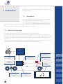
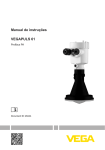
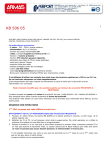
1.2 Measurement principle
The following drawing shows the theoretical working function of the reader LAURA.
The strip is inserted onto the transport belt section. The built-in strip detector recognizes the strip and starts to
movement on. The strip reaches the measuring position after approx. 55 sec. after placing on transport belts. The
measurement area is illuminated by LEDs. The reflectance light goes directly into CCD unit with help of mirror and
an optical unit.
The CCD unit converts the reflectance light to the digital value and this value is transmitted to the microprocessor,
which calculates the concentrating results and printed them by the built-in thermo printer.
Image processing unit
LED
illumination
Printing
result
Optical unit
Mirror
Reagent
strips
CCD
detector
Strip
detector
3
Waste
container
Transport
belt
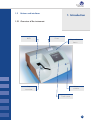
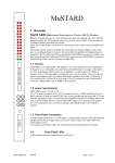
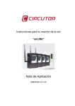
1.3 Buttons and interfaces
1. Introduction
1.3.1 Overview of the instrument
BiLED
Printer
Paper release
button
Waste container
Strip
insert area
Touch screen
4
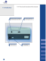
1. Introduction
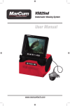
1.3.2 Overview of connection of the instrument
Connector PS2 for connecting
of external keyboard or BCR
Master switch
5
Connector RS232 for
connecting PC or LIS
Connecting of
power pack
1. Introduction
1.4 Icons and abbreviations
ID
-
Patient identification code
(a figure or a text, max. 15 characters)
Seq.No
-
Sequence number of the measurement
Sample
-
Urine specimen to be measured
REM -
Remission value
BCR -
Barcode reader
Host -
Computer (Laboratory Information System)
BiLED
-
Bicolour (red/green) LED over the strip insert area
6
2. Installation
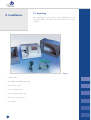
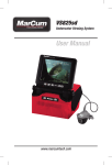
2.1 Unpacking
After unpacking the instrument, please check carefully that your package contains all the parts listed below, and all of them are in a good
condition.
Figure 1
• LAURA reader
• DC Adapter with 230 V (AC) cable
• Serial interface cable
• 2 sets of transport belts
• 2 rolls of thermo printer paper
• Tube with control grey strips
• User manual
7
2.2 Set up the instrument
2. Installation
Please follow the steps below:
• Select the working place
Choose a place for the reader, which is flat and clear.
o not place the device close to the window, centrifuge or
D
heating surface. Protect it from the direct sun light, the intensive
artificial light, vibrations and extreme temperature.
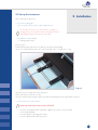
• Assemble the reader LAURA
o Placing transport belts
Refer to Fig 2.
Pull the bottom plastic part to the front and open the upper part by lifting.
Insert 1 set of transport belts to the axes in the following order: 1 long, 2 short, 1 long.
Figure 2
Save the next set of transport belts as spare part.
Check if the belts are placed correctly.
Close the instrument by turning the upper part down and pushing the bottom part back to its place.
• Connect the power and interfaces
Check if the master switch on the rear side is turned off!
o Insert the serial cable and the keyboard or BCR to the reader; use the PS2 input for the keyboard/BCR.
o Insert the adapter output plug into reader.
o Insert the adapter main cable into the net.
8
2. Installation
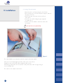
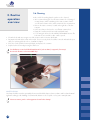
• Inserting of the printer paper
o Open the printer cover by pressing the release button.
o Place the paper roll to its holder and pull out approx. 10 cm of
the paper to the front.
o Check if the paper lies between the 2 metal ears of the printer.
o Close the cover while holding the paper tight with one hand. (Fig. 3)
o Push the cover in the middle or both sides until it clicks into its place.
Never push the cover asymmetrically!
Figure 3
The reader LAURA is now ready to be turned on; switch on the master switch!
After power-on the display lights up and the reader carries out a self test.
During this test the optic and the built in calibration PAD is tested.
After having completed the test successful, the reader prints out the “OK” message and goes into the Standby mode.
The reader is now ready for measurement.
9
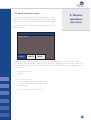
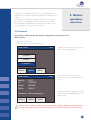
3.1 Ready to measure status
This is the status where the instrument after performing the self test
waits for user command. The instrument has a touch-sensitive display.
The user can control the instrument by pressing the displayed buttons.
3. Routine
operation
overview
In the Ready to Measure status the following possibilities are available for the user:
INSERT STRIP!
12:23
Seq.No: 0001
PATIENT
SAMPLE
MENU
Start a new measurement process by placing a strip on the transport belts in the insert strip area. In ready to
measure mode the reader LAURA is ready to measure, the bicolour LED lights green over the strip insertion area
and shows that the reader can accept the next strip. The SeqNo and the ID of the next strip is displayed on the
touch screen.
• Enter patient information:
o Seq.No
o ID
•
Enter sample information:
o Select a sample colour from the predefined list
o Select a sample clarity from the predefined list
o Insert comment
• Enter the menu by pressing the MENU icon.
10
3. Routine
operation
overview
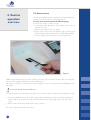
3.2 Measurement
The instrument LAURA begins the measurement automatically when a
strip is placed on the strip area on the transport belts.
To carry out a measurement do the following steps:
• Enter a new Seq.No. or ID if necessary
• If you want to define appearance of the sample, select a colour or
clarity from the offer
• Dip the reagent strip into the urine sample
• Remove excess urine from the strip (Push the edge of the strip to an
absorbent paper, follow instruction for the strips PHAN® LAURA)
• Insert the strip into the insert strip area on the transport belts
Figure 4
LAURA has a build-in strip detector at the end of the insert area, under the belts. If the strip is placed correctly this
detector will recognize it and the bicolour LED will flash green.
After a few seconds (2-7 seconds) the bicolour LED change the colour to the red and reader LAURA shift the strip
into reader.
Do not touch the strip when the red LED is on!
The strip will reach the measurement position after 55 seconds. The reader measures the strip and prints the result.
• T he reader LAURA increments the Seq.No. automatically and displays it. The bicolour LED turns back green
and the reader can accept another strip. The minimum time between placing two strips on the belt is 9 seconds.
• After the strip was measured, it falls into the waste container.
The other result parts are stored in the memory.
11
When all placed strips have been measured, the instrument stops
the transport belts and turns back into Standby. The type of the strip
(DekaPHAN® LAURA or HeptaPHAN® LAURA) will be recognised
automatically.
3. Routine
operation
overview
The instrument counts the amount of placed strips and gives a warning message when it reaches 100 pcs:
Waste container full!
In such a case the reader doesn’t accept more strips. Don’t touch the
icon STOP. Wait until the already placed strips will be processed and the measurement stops automatically. Then
make the container empty, and continue the measurement.
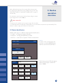
3.3 Patient identification
LAURA reader supports 3 different sample (patient) identifications:
• Seq.No – working with Sequence Number
• Patient ID – working with Identification number
• Work list – create the list of patients’ ID before measurement
INSERT STRIP!
12:23
Seq.No: 0001
Seq.No.
In order to enter a new Seq No the
user has to touch the PATIENT button
and then select the SEQ.NO button.
SEQ.NO
ID
PATIENT
Seq.No:
SAMPLE
MENU
The following numeric PAD will appear
and the user can type a number between 1-9999.
1234
1
2
3
4
5
6
7
8
9
ESC
OK
0
12
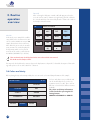
Patient ID
After selecting the ID button a similar edit field appears, where the
user can enter a max 15 characters long ID string. This ID could also
be entered with help of an external keyboard or a barcode reader in
the Ready to Measure status.
3. Routine
operation
overview
ID:
Work list
In this mode, more sample IDs could be
entered before the measurement is started. The reader LAURA can accept 100
sample IDs and store them in memory.
After all the IDs are stored, the measurement can start. The reader displays the
ID of that strip which is to be placed
next. This mode can be reached under
the MENU/WORKLIST (see bellow).
ABCD1234abcd
_./
ABC
DEF
ESC
GHI
JKL
MNO
abc
PQR
TUV
WZXYZ
OK
-(#)
Take care that the strips should be placed in the same order as the IDs were entered.
Else the IDs and the samples will mix!
If a strip in the list should not be measured, press the skip button to skip its ID. For detailed description of this working mode please refer to: 4.2.1 Work list – submenu
3.4 Colour and clarity
Before placing the strip to the transport belts, the user can set the colour and clarity information of the sample.
INSERT STRIP!
12:23
YELLOW
COLOUR
RED
CLARITY
GREEN
COMMENTS
BROWN
PATIENT
13
SAMPLE
MENU
Colours and clarities are predefined and
can be modified by the user in the customisation menu (see 4.6). There are four
different colours and four different clarities
available.
The colour and clarity information
will be listed after pressing the following buttons:
SAMPLE and COLOUR or CLARITY:
Pressing the desired button will select the corresponding information.
It will appear on the display and will be added to the next measured
sample.
For deleting the previously selected information, the user can go into
the selection menu again but instead of selecting a value from the
list the COLOUR or CLARITY button has to be pressed again. In this
case the program clears the previously set value.
3. Routine
operation
overview
3.5 Comments
It is possible to add comments (39 characters long) to the measurements at two
different points:
• Before the measurement
• When the result is selected from the memory
INSERT STRIP!
12:23
To add a comment before a measurement
starts use the following buttons:
12:23
This picture shows an example screen
when all measurement related parameters
are set:
COLOUR
CLARITY
COMMENTS
PATIENT
SAMPLE
MENU
INSERT STRIP!
Seq.No:
ID:
Colour:
Clarity:
0001
125X333
YELLOW
CLEAR
Comments: Short comment to …
PATIENT
SAMPLE
Possibility to add the comments after measurement is in menu MEMORY, please refer
chapter 4.2.2
MENU
Remember that if you add any comments before measurement and would like to add next comments after measurement to the same sample, you have to overwrite the previous text, in other case will be the previous text deleted.
14
3. Routine
operation
overview
•
•
•
•
3.6 Cleaning
At the end of the working day the reader is to be cleaned.
• We recommend using the one-off waist container for collecting of
measured strips, which cumulating in the waist container. Put the
one-off waist container to the waist container before measurement.
• Remove the waste container, located at the right side of the bottom part
• In the case, that you don’t use the one-off waist container, then
• Empty the container and clean it with usual disinfectant.
• For cleaning the belts select the MENU/CLEANING function. The
belts start to move and the reader can be opened.
Clean the belts and axes using a wet cloth, moistures with a common disinfectant.
Pay attention that the belts remain in their track. If it is necessary, the belt could be removed and washed separately. For replacing the belts refer to „Installation“chapter.
Close the reader, push the bottom part back, and replace the container
Stop the belt movement by pressing the STOP icon
For disinfection, use an alcohol disinfectant (max 85 %) such as ethanol, isopropanol, if necessary!
Do not touch the mirror or the internal REF strip!
WASTE DISPOSAL:
Used strip should be treated as potentially infectious and should be disposed in accordance with local and national
regulations relating to safe handling of such materials. Waste is to be recycled or to be put to municipal waste.
15
Never use acetone, petrol or other aggressive solvents for the cleaning!
LAURA reader has a clear, well organized menu structure. The user is
guided trough the menu by the touch screen. The menu functions are
represented by buttons or list controls.
Pressing the touch screen can activate the desired function.
The pressed buttons are highlighted with blue colour.
Pressing the button ESC, the program jumps back to the previous
menu level. The program jumps back to Standby, if any button isn’t
pressed for 3 minutes.
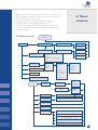
4.1 Menu overview
MENU
4. Menu
structure
Standby
Ready to measure
Patient information
ID
Seq.No.
MEASUREMENT
WORK LIST
Colour
Clarity
Create
Delete
Start of measurement
Print
MEMORY
CHECK MODE
All
Today
Date
CLEAN
SETUP INSTRUMENT
Code
Sample information
Strip
Comment
Seq.No.
ID
All
Positive
Not printed
Not send
Error
Sediment
Parameters
Order
Print
Display
Send
Delete
Unit
Sediment
Sensitivity
Default
New
User interface
Printer Sound ID MODE ON/OFF
Language
EN, CZ, PL, RU, DE, HU, IT
Date /Time
HW interface
Customization
Logo: On / Off
Header text: 1 / 2
Greetings text: 1 / 2
Colour text: 1 / 2 / 3 / 4
Clarity text: 1 / 2 / 3 / 4
16
4. Menu
structure
4.2 Main menu
After pressing the MENU in Ready to measure status the following
main functions are available:
INSERT STRIP!
Seq.No:
0001
12:23
WORKLIST
MEMORY
CHECK MODE
CLEAN
SETUP INSTRUMENT
PATIENT
SAMPLE
MENU
• WORKLIST
In this mode, more sample IDs could be entered before the measurement is started. The reader LAURA can
accept 100 sample IDs and store them in memory. After all the IDs are stored, the measurement can start. The
reader displays the ID of that strip which is to be placed next.
• MEMORY
LAURA reader has a memory for the last 1 000 measurements.
The stored measurement results with all of their related information (date, time, comment, colour…), can be
selected from the memory, displayed, printed or sent to the computer anytime.
• CHECK MODE
With this function the instrument measuring capability could be tested, by using the grey control strips. The
instrument measures the grey control strips and compares the result to the predefined values. The test result is
displayed and also printed for QC purposes.
• CLEAN
This mode assists by cleaning the transport belts. When this function is selected, the reader switches on the
transport belts without starting a measurement.
• SET UP INSTRUMENT
In this menu point the working parameters of the reader could be set.
17
4.2.1 Work list
This menu serves to create a list of sample IDs and to start the
measurement in Work list mode.
The following functions are available:
4. Menu
structure
WORKLIST
CREATE
DELETE
The individual menu functions could be
activated by pressing the corresponding
button.
MEASUREMENT
ESC
PRINT
To enter new ID, select button CREATE:
ID can be entered either by using the
numeric or letter buttons or from an external
keyboard or BCR. The amount of stored
IDs is displayed. Maximum 100 IDs could
be preset in this way. If the Work list was
not empty when entering the Create mode,
the stored items figure displays the total
number of stored IDs. When the button OK
is pressed, the process is finished and the
reader jumps back to the Work list menu.
ENTER ID
Stored item:0003
ID
OK
By selecting button DELETE, the whole work list could be deleted. The reader asks for confirmation before deletion.
INSERT STRIP!
Seq.No:
ID:
PATIENT
12:23
0001
125X333
SAMPLE
STOP
The Work list mode measurement can be
started with the button MEASUREMENT.
The display shows the following
information:
SKIP
18
The ID field displays the 1st item of the work list and the reader accepts the first strip. The reader moves the strip into reader and the instrument asks for the next strip and displays the next stored ID. The ID
of the measured samples will be removed from the work list. The ID
stored in the instrument cannot be changed, only skipped by pressing
the button SKIP. The reader jumps to the next ID and the skipped ID
remains in the list for further measurement.
4. Menu
structure
The sequence number of the samples can be set freely.
Take care that the strip should be placed in the same order as the IDs were entered to the worklist and the reader
shows it on the display. Else the IDs and the samples will mix!
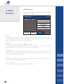
4.2.2 Memory
The reader has a non-volatile memory, which automatically stores the last 1 000 measurements.
The oldest result will be overwritten by the new measurement without any warning.
When the current measurement is ready the reader stores the result along with the following parameters:
• Test result
• Type of the strip
• Seq.No
• ID
• Date and time
• Colour
• Clarity
• Comment
The user can reach the memory from the Menu by selecting the Memory button.
For administration of the memory the following display appears:
MEMORY
FILTER
ALL
DAY
ALL
ACTION
ESC
19
FILTER and DAY buttons serve to set the
selection parameters, after that the START
button activates the selected action.
DISPLAY
START
The desired measurement can be selected in the following way:
• Select the FILTER criterion:
o All - all stored result
o ID - enter the desired ID
o Seq.No - enter the desired SeqNo
o Not printed - results that where not printed yet
o Not sent - results that where not sent yet
o Positive - where at least 1 value was positive
o Sediment - if at least 1 value is higher then the sediment limit,
defined under Parameter settings
o Error - when the measurement failed
•
Select the DAY of the measurement:
o All - regardless of the date
o Today - searching only among the today measured results
o Specific date - select the desired day
(The program offers only those days for which there are results in the memory.)
•
Choose an ACTION (what should happen with the selected results):
o Display - the selected measurements will be displayed
o Print - the selected measurements will be printed
o Send - results will be sent to HOST, RS232
o Delete - measurements corresponding to the selection criterion will be deleted
4. Menu
structure
After all of the three above mentioned parameters (Filter, Day and Action) have been defined, the process can be
activated by pressing the START button.
In case that DISPLAY was selected the appropriate results are displayed as follows:
MEMORY: 1 / 3 DekaPHAN LAURA
Seq.No: 0023
BLD ID: *LEU
03.10.2008 18:08
BIL
Colour: YELLOW
UBG
Clarity: CLEAR
KET
*GLU
COMMENTS:
PRO
pH
NIT
SG
ESC
12:23
NEG
75
NEG
NORM
NEG
50
NEG
6.5
NEG
1.025
Leu/ul
mg/dl
PRINT
The last measurement in the list will be displayed as the first one.
the user can step forward or backward in the list.
With help of the buttons
The currently displayed result could be printed and a new comment could be attached.
Positive parameters are marked with* and are displayed in yellow colour. The result can be printed any time by
pressing the PRINT button.
20
4.2.3 Check mode
4. Menu
structure
The purpose of this test measurement is to verify that the optical
measuring capability of the instrument works properly. Perform this
test once a week, or if you receive suspicious result in normal use.
For testing the instrument the grey control strips are provided in the
LAURA reader package.
The strips are labelled 1 and 2.
Perform the test as follows:
• Empty the waste container and clean it carefully!
•
•
•
•
•
•
The strip falls into the container and could be contaminated!
Press the button CHECK MODE from the main menu
Take out one pair (1 and 2) of grey strips from the tube
Place the grey strip 1 onto the belts
The reader starts the measurement then expects the grey strip 2
Place the grey strip 2 onto the belts
Wait for the measurement is complete
After measurement the reader compares the obtained remission values to the predefined ranges, stored in the
instrument, in every greyscale and wavelength. After that it displays and prints out the result.
When the measured values are in harmony with the predefined values the result of the QC Test is OK.
The display after QC Test is follows:
TEST MEASUREMENTS
1:
2:
3:
ESC
21
690
350
145
Test: OK
12:23
700
354
130
Print out the result of the measurement:
4. Menu
structure
Keep the print out for QC reference.
If the test fails, Test Error will be reported and the wrong result is displayed in red. In this case repeat the test with
another check strip. If it reports an error again call the service.
Keep the grey strips always in the tube, do not touch the surfaces by hand, and handle them with care. The strips
are reusable. Refer to the label of the grey strips tube!
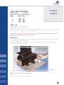
4.2.4 Clean
This mode assists by cleaning the transport belts. When this function is selected, the reader switches on the transport belts without starting a measurement.
The reader LAURA can be opened and the belts could be accessed and wiped off easily (Fig. 5). To quit this
mode the STOP button is to be pressed.
Figure 5
Do not touch the mirror or the internal REF strip!
For more information, please refer to section 3.6.
22
4. Menu
structure
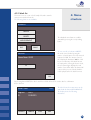
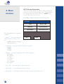
4.2.5 Set up of instrument
This menu point of the instrument is usable for setting of working parameters. To avoid an accidental change of these setting parameters,
is the Settings menu code protected. The code is 2134. Enter this
code then press OK to enter the menu.
The available settings are displayed in the following format:
SETTINGS
STRIP
DATE / TIME
USER INT.
HW INTERFACE
LANGUAGE
CUSTOMIZATION
The working parameters are organized
as follows:
• Parameter – strip and measurement
related parameters could be set here,
as:
ORDER of parameter at printing
UNIT of parameters
ESC
•
User interface – turning ON/OFF the following user interfaces:
PRINTER
SOUND
ID MODE
•
Language – selecting the language from the 7 defined languages:
EN – English
DE – German
IT – Italian
CZ – Czech
PL – Polish
HU – Hungarian
RU – Russian
PRINT
• Date / Time – set the date and time and the date format
• HW Interface – serial communication parameter settings
• Customisation – customizing the header text and logo, defining colour and clarity texts
23
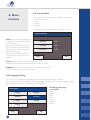
4.3 Strip menu -parameter settings
4. Menu
structure
This menu point is divided into two submenus:
• Printing order
• Unit settings
STRIP
4.3.1 Printing order
ORDER OF PAR.
DEFAULT
NEW
ESC
OK
ORDER OF PAR.
1: pH
2: PRO
3: SG
BLD
LEU
BIL
UBG
KET
GLU
ESC
The parameter printing order can be set in
the following menu point:
After pressing the DEFAULT button the
printing order will correspond to the
Parameter order of the strip DekaPHAN®
LAURA.
The instrument enables to change this
order according to the user’s wish. In this
case the NEW menu point should be used.
The program offers all the parameters and
they should be touched one after each
other in the desired order.
OK
PARAMETER: BLD
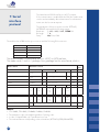
4.3.2 Unit settings
The user set the unit individually for each
parameter. The parameter is displayed in
the header of the LCD and the desired unit
can be set individually.
The following table lists the possibly reported values for all of the three types of units:
Unit
Conv Ery/ul
Sediment
50
Sensitivity
0
ESC
Possibilities for settings of units are CONV,
SI and ARB or their combination.
OK
The following table summarizes the
possible reported values.
24
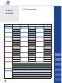
4.3.3 Parameter table
4. Menu
structure
Parameter
BLD
LEU
BIL
UBG
KET
GLU
PRO
pH
NIT
SG
25
CONV
value
NEG
10
50
250
NEG
25
75
500
NEG
1
3
6
NORM
1
3
6
12
NEG
5.2
16
52
156
NORM
50
100
300
1000
NEG
30
100
500
unit
Ery/µl
Leu/µl
mg/dl
mg/dl
mg/dl
mg/dl
mg/dl
SI
value
NEG
10
50
250
NEG
25
75
500
NEG
17
51
103
NORM
17
51
102
203
NEG
0.5
1.5
5
15
NORM
2.8
5.5
17
55
NEG
0.3
1
5
5
6
6.5
7
8
9
NEG
POS
1.000
1.005
1.010
1.015
1.020
1.025
1.030
ARB
unit
Ery/µl
Leu/µl
µmol/l
µmol/l
mmol/l
mmol/l
g/l
value
NEG
1+
2+
3+
NEG
1+
2+
3+
NEG
1+
2+
3+
NORM
1+
2+
3+
4+
NEG
±
1+
2+
3+
NORM
1+
2+
3+
4+
NEG
1+
2+
3+
4.3.4 Sediment settings
The reader LAURA can filter the measurements in order to find out
which samples should be investigated for sediment analysis.
For this purpose sediment limit could be defined for each parameter
(see 4.3.2. unit settings). If the measured result is higher than this set
limit, then the measurement is marked as relevant for the sediment.
After the chemical measurement is over, the instrument can print a list
with the Seq.No and ID of those measurements where at least one
parameter was higher then the defined sediment limit.
4. Menu
structure
To do it, follow these steps:
• Select Menu
• Select Memory
• Set Day: Today
• Set Sel: Sediment
• Set Act: Print List
• Press OK
The reader LAURA will print a list of samples that should be further processed.
4.3.5 Sensitivity settings
The reader LAURA allows the user to slightly change the instrument sensitivity, for each parameter individually.
The sensitivity can be set in ± 5 points, where:
0 is no change,
-1 to -5 is less sensitive,
+1 to +5 is more sensitive.
The sensitivity value changes the measured remission value before it is compared to the predefined remission borders. The change is valid proportionally for the whole measuring range, from NEG to the highest POS value.
Notice that the sensitivity has an influence on the instrument performance!
26
4. Menu
structure
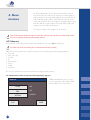
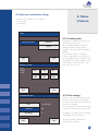
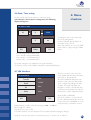
4.4 User Interface
In this menu point the built in interfaces could be switched ON or
OFF. These interfaces are:
• Printer
• Sound
• ID Mode
The factory setting for all this interfaces for LAURA® is the next:
USER INTERFACE
Printer ON /OFF indicates whether the
results will be printed automatically after
measurement, or not.
It is possible to switch off this feature; in
this case the instrument will measure the
strip and store the results in the memory,
but it won’t be printed.
The result can be printed at any time
from the memory or when the result is
displayed.
PRINTER
ON
SOUND
ON
ID MODE
OFF
ESC
OK
Sound ON/OFF turns the button feedback beep on or off.
Warning beeps are always ON, this setting has no influence on them.
ID MODE In this case the equipment doesn’t start the measure without ID, so the user need to type in the ID of the sample.
4.5 Language Setting
The user can select in this menu the language, which want to communicate with the instrument.
The selection can be performed using the corresponding button. The button of the currently set language is highlighted. OK button must be pressed to make the selection valid.
The following languages
are available:
English
German
Italian
Czech
Polish
Hungarian
Russian
LANGUAGE
English
Magyar
Deutsch
Pycckuu
Polski
Italiano
Česky
ESC
27
OK
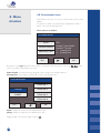
4.6 Date / Time setting
4. Menu
structure
The Time and the Date format can be set in this menu point.
Select the Date / Time button in settings menu, the following
display will appear:
SET DATE / TIME
03
ESC
11
2008
11
49
FORM
OK
To change the date or time values push
the corresponding button!
A numeric PAD will appear and the desired value can be entered.
When date and time are correct the DATE
format can be set, by pressing the FORM
button.
The following formats could be used:
Year – Month – Day (YYYY-MM-DD)
Day – Month – Year (DD-MM-YYYY)
Month – Day – Year (MM-DD-YYYY)
The update settings become valid after pressing the OK button.
The real time clock in reader LAURA is running from a built in lithium battery.
4.7 HW Interface
This menu is used for connection of the
reader LAURA with laboratory information
system (LIS) or directly with PC.
The reader LAURA has an RS 232 serial
interface to HW connection. This interface
can be configured according to the HW
computer. The format of the data, sent
through the serial line, is described bellow.
In this menu point the parameters of the RS
232 interface could be adjusted as follows:
HW INTERFACE
Transfer
Auto
Baud
19 200
Bit
8 bit
Parity
None
ESC
OK
Mode: AUTO or MEMORY
If the mode „AUTO“ is on, the results will
be sent to HW immediately after the measurement; if the mode „MEMORY“ is on, the
results will only be sent from the memory.
Baud: Baud rate could be selected in the range 2 400 – 19 200 Bd
Bit: bit length of 7 or 8 bits
Prty: parity none, even, or odd
Press OK to make the selection valid; press ESC to jump back without saving the changes.
Details for connection are written in serial interface protocol – please refer to chapter 7.
28
4. Menu
structure
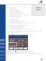
4.8 Customization menu
Customization menu serves to enter user defined texts into the reader
LAURA.
The text lines could be entered with help of alphanumeric PAD or
with a connected external keyboard:
These texts are as follows:
CUSTOMISATION
LOGO
PRINTER HEADER
GREETINGS LINE
ON
Header 1st line 123456
Header 2nd line lab
1st greetings line
2nd greetings line
ESC
OK
Beyond these, the Logo ON/OFF switch could be reached from this menu point. In case logo
set, the logo will be printed with every result.
Printer header - 2 header lines appearing with each result print out, max 24 characters
Greetings line - 2 greeting lines, printed after self test, max 24 characters
CUSTOMISATION
Colour text 1
COLOUR
Colour text 2
CLARITY
Colour text 3
Colour text 4
ESC
OK
Colour - 4 different colour texts, max 10 characters each
Clarity - 4 different clarity texts, max 10 characters each
Paging could be done by pressing the buttons
29
ON is
The reader LAURA is a high sensitive and accurate optical measuring
instrument.
All optical components, such as the mirror, objective, reference field
are adjusted with special tools during manufacturing. Do not remove
the cover plates, and never touch the mirror and the reference field
when the instrument is open for cleaning.
5. Service
information
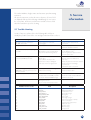
5.1 Trouble-shooting
In case of any error, please refer to the following table. It helps to
identify the possible cause of the error and gives instruction how to solve it.
Error description
Possible cause
Corrective action
The reader cannot be switched on.
The LCD remains dark.
Power supply is not connected, or wrong type.
Check the power supply and the connections.
Self-test failed.
The instrument is not closed.
Close the upper part. Insert the bottom
plastic part and waste container.
The reader doesn’t print, or the printing is
not visible.
Paper cover is not closed.
Wrong paper is in (not thermal paper).
Paper is inserted with wrong side up.
Check the printer visually, for any damage or jam.
Insert the right type of paper correctly.
Close the printer cover.
The reader does not recognize the
inserted strip. BiLED doesn’t flash.
Reader is in ID mode, and no ID was given.
Strip is placed extremely to side.
Strip detector is dirty or damaged.
Plexi cover is not in the right position.
Enter an ID.
Move the strip to the middle of the insert area.
Remove the plexi cover and test the detector.
Check the detector for damage or extreme dirt.
Push back the plexi to its position.
The reader recognises the placed strip,
BiLED flashes on green, but the strip is not
transported inside.
The transport mechanism is damaged.
Rubber belts are missing.
Flip up the reader.
Check the transport belts.
Host communication failed.
Serial cable is not attached or wrong.
Interface mode is turned OFF, or parameter doesn’t match with HOST settings.
Check the cable!
Check that interface mode is ON and
parameters are correct.
Reader displays Measurement Error.
Strip is placed wrong.
Wrong strip is used.
Dry or not fully moistured strip is used.
Repeat the measurement with correct strip.
Number of error codes
1
2
3
4
5
6
7
8
9
10
11
12
13
14
Code
ERR_EE
ERR_RTC
ERR_COMM
ERR_EXTLIGHT
ERR_WRONGSTRIP
ERR_STRIPWIDTH
ERR_SRSTRIP
ERR_DRYSTRIP
ERR_PAPER
ERR_LOGIN
ERR_OPEN
POP_EMPTY
POP_EMPTYWL
POP_NEWVAL
Description
EEprom fails HW error
RTC ack fails HW error
Communication error
Extern light too high
Wrong strip
Strip to wide
Strip angle too high
Strip not inserted fully in sample
Printer out of paper
Login failed not implemented
Upper part open
Memory empty
Worklist empty
Setting stored
30
5. Service
information
5.2 Service information
In case of an error, try to solve it according to the above troubleshoot guide first.
If the failure remains, please contact your distributor for service.
Never open the reader’s case.
5.3 Safety information
T he reader LAURA complies with the EMC directive 89/336/EEC
and low voltage directive 73/23/EEC.
LAURA instrument in combination with PHAN® LAURA test strips complies with the requirements of IVD directive 98/79/EC.
5.4 Producer
Producer of the system LAURA and diagnostic strips PHAN® LAURA:
Erba Lachema s.r.o.
Karásek 1d, 621 33 Brno
Czech Republic
5.5 Ordering information
cat. number:
LAURA reader DekaPHAN® LAURA HeptaPHAN® LAURA LAURA one-off waist container The Grey control strips for LAURA –
–
–
–
–
50001727
10008297
10008298
50003091
50003491
5.6 Guarantee conditions
The guarantee conditions are included in the sales agreement.
31
6. Technical
parameters
General
Measurement
User Interface
Memory
Interfaces
Recommended operating
environment
Storing / transport
Dimensions
430×290×170 mm
Weight
7 kg
Power source
External adapter
7,5 V DC / 6 A, 90–230 V/ 50–60 Hz
Power consumption
max / standby
45 W / 6 W
Method
Reflection photometry
Throughput
max. 400 Strips/hour
Wavelength
535, 610 nm
Optic viewing area
100 mm
Pixel resolution
640 pixels / 100 mm
AD resolution
12bit
Printer
58 mm graphical thermal printer, 24 chars/line
Coloured tooch screen
5“ TFT (320×240 pixels)
Capacity
1000 measurement results with date, ID, and comments
RTC
Lithium battery for keeping real time clock on
Host interface
RS 232 Serial interface,
2 400–19 200 Bd
BCR
Wedge type BCR with standard PS2
interface, max. range 13 chars
PC AT / keyboard
Wedge type BCR with standard PS2
interface
Temperature
15–35 °C
Optimal range 20–25 °C
Humidity
20–80 %
Place
Horizontal surface
No shock or vibration
Temperature
-20 – +60 °C
Humidity
20–90 %
32
The LaUra has an RS232 interface to HOST computer.
If the communication is enabled (Mode: ON) the reader sends
out the result immediately after measurement. Stored measurements can also be sent at any time.
7. Serial
interface
protocol
The parameters of the port can be set in the SETTING/
INTERFACE menu within the following ranges:
Baud rate: 2 400, 4 800, 9 600, 19 200 Bd
Bit length
7, 8
Parity: No, Even, Odd
The interface has a DB9 mother type connector with the following PIN connection:
PIN number
Connected
2
TxD
3
RxD
5
GND
1, 4, 6, 7, 8, 9
- not connected
The communication is unidirectional LaUra -> HOST, in ASCII text form.
The reader sends 1 result in 1 package. Every package has the same format, which is:
# of
bytes
Name of field
Characters sent out
Frame start
STX
Seq.No line
“Seq.No:”
7 char
SP
4 char long Seq number, right
justified, filled with 0
ID line
“Pat.ID:”
7char
SP
14 char long ID
COLOR
„COLOR:“
3×SP
CLARITY
„CLARITY:“
SP
Strip name
9 space
CR, LF
26
CR, LF
26
CR, LF
26
Color text 10 char
CR.LF
21
Clarity text 10 char
CR LF
21
6×SP
2×SP
Date line
YYYY.MM.DD
3×SP
CR, LF
26
1st. result line
‘*’
or
SP
SP
3char
par.
name
SP
5char
result
Conv
or SI
SP
HH:MM
6char
unit
SP
5char
ARB
result
CR, LF
26
10th. result line
‘*’
or
SP
SP
3char
par.
name
SP
5char
result
Conv
or SI
SP
6char
unit
SP
5char
ARB
result
CR, LF
26
Comment line
{
}
82
Frame end
ETX
80 char long comment or space
Where:
• STX = 0x02, ETX= 0x03, CR=0x0d, LF=0x0a, SP=0x20
• The parameter order is the default regardless of printing order.
• In case of Hepta-PHAN only 7 parameter line is sent
• The result and the unit is depending on the selected unit (SETTINGS/STRIP/PARAMETER)
33
1
8. Short
Instructions
1. C
heck carefully if the instrument is complete and all parts are placed in correctly (waste container, transport
belts etc.)
2. Connect the instrument to the plug with the relevant cable, check if there is a connection between the instrument and external plug.
3. Switch on the instrument with the main switch.
4. Wait till the instrument performs the self-test.
5. Set the mode of the results (direct printing after analysis, printing after measurement of all samples, sending to
the external net etc.).
6. Now you can start with measurement in the mode SeqNo or you can start with creating of the work list in
MENU/Work list.
7. C
omplete the measurements of urine samples; follow all recommendations during the operation, which are
included in the instruction of the diagnostic strips.
8. Perform the everyday cleaning after having finished your daily measurements.
9. Now you can leave the instrument switched on in Standby mode or you can switch it off using the main switch.
34
9. Index
Adapter Belts Check mode Clarity Colour Comments Customization Date ID Installation Interface Language Logo Measurement Memory Menu Parameter Printer Sample Sediment Sensitivity Seq.No. Set up Sound Strip Time Units Work list 35
7, 8
3, 7, 8, 10, 11, 15, 17, 21, 22, 34
17, 21
10, 13, 14, 19, 29
10, 13, 14, 19, 29
10, 14, 19, 20
23, 29
17, 19, 20, 23, 28
6, 10, 11, 12, 13, 17, 18, 19, 20, 27
7, 15
7, 23, 27, 28, 33
23, 27
23, 29
3, 9, 10, 11, 17, 18, 19, 20, 21, 22, 34
11, 17, 19, 26
10, 13, 15, 16, 17, 23, 24, 27, 28, 29
19, 23, 24, 25, 33
3, 4, 9, 27, 29, 32
3, 6, 10, 11, 12, 13, 14, 17, 18, 26
20, 24, 26
24, 26
6, 10, 11, 12, 19, 20
8, 17, 23
23, 27
3, 4, 7, 11, 17, 19, 21, 22, 23, 24, 31, 34
17, 19, 23, 28
23, 24, 25
13, 17, 18, 34